EP1171945B1 - Method for producing a magnetically excitable core comprising a core winding for an electric machine - Google Patents
Method for producing a magnetically excitable core comprising a core winding for an electric machine Download PDFInfo
- Publication number
- EP1171945B1 EP1171945B1 EP01907382.4A EP01907382A EP1171945B1 EP 1171945 B1 EP1171945 B1 EP 1171945B1 EP 01907382 A EP01907382 A EP 01907382A EP 1171945 B1 EP1171945 B1 EP 1171945B1
- Authority
- EP
- European Patent Office
- Prior art keywords
- core
- winding
- groove
- sides
- slot
- Prior art date
- Legal status (The legal status is an assumption and is not a legal conclusion. Google has not performed a legal analysis and makes no representation as to the accuracy of the status listed.)
- Expired - Lifetime
Links
Images


Classifications
-
- H—ELECTRICITY
- H02—GENERATION; CONVERSION OR DISTRIBUTION OF ELECTRIC POWER
- H02K—DYNAMO-ELECTRIC MACHINES
- H02K1/00—Details of the magnetic circuit
- H02K1/06—Details of the magnetic circuit characterised by the shape, form or construction
- H02K1/12—Stationary parts of the magnetic circuit
-
- H—ELECTRICITY
- H02—GENERATION; CONVERSION OR DISTRIBUTION OF ELECTRIC POWER
- H02K—DYNAMO-ELECTRIC MACHINES
- H02K15/00—Methods or apparatus specially adapted for manufacturing, assembling, maintaining or repairing of dynamo-electric machines
- H02K15/06—Embedding prefabricated windings in machines
- H02K15/062—Windings in slots; salient pole windings
- H02K15/065—Windings consisting of complete sections, e.g. coils, waves
- H02K15/066—Windings consisting of complete sections, e.g. coils, waves inserted perpendicularly to the axis of the slots or inter-polar channels
-
- H—ELECTRICITY
- H02—GENERATION; CONVERSION OR DISTRIBUTION OF ELECTRIC POWER
- H02K—DYNAMO-ELECTRIC MACHINES
- H02K15/00—Methods or apparatus specially adapted for manufacturing, assembling, maintaining or repairing of dynamo-electric machines
- H02K15/02—Methods or apparatus specially adapted for manufacturing, assembling, maintaining or repairing of dynamo-electric machines of stator or rotor bodies
- H02K15/024—Methods or apparatus specially adapted for manufacturing, assembling, maintaining or repairing of dynamo-electric machines of stator or rotor bodies with slots
-
- Y—GENERAL TAGGING OF NEW TECHNOLOGICAL DEVELOPMENTS; GENERAL TAGGING OF CROSS-SECTIONAL TECHNOLOGIES SPANNING OVER SEVERAL SECTIONS OF THE IPC; TECHNICAL SUBJECTS COVERED BY FORMER USPC CROSS-REFERENCE ART COLLECTIONS [XRACs] AND DIGESTS
- Y10—TECHNICAL SUBJECTS COVERED BY FORMER USPC
- Y10T—TECHNICAL SUBJECTS COVERED BY FORMER US CLASSIFICATION
- Y10T29/00—Metal working
- Y10T29/49—Method of mechanical manufacture
- Y10T29/49002—Electrical device making
- Y10T29/49009—Dynamoelectric machine
-
- Y—GENERAL TAGGING OF NEW TECHNOLOGICAL DEVELOPMENTS; GENERAL TAGGING OF CROSS-SECTIONAL TECHNOLOGIES SPANNING OVER SEVERAL SECTIONS OF THE IPC; TECHNICAL SUBJECTS COVERED BY FORMER USPC CROSS-REFERENCE ART COLLECTIONS [XRACs] AND DIGESTS
- Y10—TECHNICAL SUBJECTS COVERED BY FORMER USPC
- Y10T—TECHNICAL SUBJECTS COVERED BY FORMER US CLASSIFICATION
- Y10T29/00—Metal working
- Y10T29/49—Method of mechanical manufacture
- Y10T29/49002—Electrical device making
- Y10T29/4902—Electromagnet, transformer or inductor
- Y10T29/49071—Electromagnet, transformer or inductor by winding or coiling
-
- Y—GENERAL TAGGING OF NEW TECHNOLOGICAL DEVELOPMENTS; GENERAL TAGGING OF CROSS-SECTIONAL TECHNOLOGIES SPANNING OVER SEVERAL SECTIONS OF THE IPC; TECHNICAL SUBJECTS COVERED BY FORMER USPC CROSS-REFERENCE ART COLLECTIONS [XRACs] AND DIGESTS
- Y10—TECHNICAL SUBJECTS COVERED BY FORMER USPC
- Y10T—TECHNICAL SUBJECTS COVERED BY FORMER US CLASSIFICATION
- Y10T29/00—Metal working
- Y10T29/49—Method of mechanical manufacture
- Y10T29/49002—Electrical device making
- Y10T29/4902—Electromagnet, transformer or inductor
- Y10T29/49073—Electromagnet, transformer or inductor by assembling coil and core
-
- Y—GENERAL TAGGING OF NEW TECHNOLOGICAL DEVELOPMENTS; GENERAL TAGGING OF CROSS-SECTIONAL TECHNOLOGIES SPANNING OVER SEVERAL SECTIONS OF THE IPC; TECHNICAL SUBJECTS COVERED BY FORMER USPC CROSS-REFERENCE ART COLLECTIONS [XRACs] AND DIGESTS
- Y10—TECHNICAL SUBJECTS COVERED BY FORMER USPC
- Y10T—TECHNICAL SUBJECTS COVERED BY FORMER US CLASSIFICATION
- Y10T29/00—Metal working
- Y10T29/49—Method of mechanical manufacture
- Y10T29/49002—Electrical device making
- Y10T29/4902—Electromagnet, transformer or inductor
- Y10T29/49075—Electromagnet, transformer or inductor including permanent magnet or core
- Y10T29/49078—Laminated
Definitions
- stator core which thus has on one side for a stand usual parallel aligned teeth and grooves.
- An already pre-wound, designed as a distributed wave winding core winding is approximately in a flat shape and is then inserted into the grooves of the substantially flat core.
- the flat assembly of core and core winding has a so-called winding overhang, that is, each of a total of three phases has one Winding side, which is initially not inserted in grooves.
- This assembly of core and core winding is then bent around so that a conventional hollow cylindrical stator is formed. In this case, the overhanging sides of the winding must be finally inserted into the corresponding slots prior to the completion of the stand.
- the core Due to its production, the core has two ends which are flush with each other when bending the core with the core winding. These two ends are geometrically placed in the groove bottom of a core groove.
- the invention is based on the finding that the flared prior to the round bending of the laminated core grooves are to be filled so that the inserted winding already corresponds to the round bending at least approximately the shape of the grooves after the round bending, with a certain pressure within the inserted winding is quite desirable.
- each half-formed tooth is that the magnetic resistance in the magnetic yoke of the stator core is not interrupted and thus magnetic losses are reduced.
- the individual coil or loop sides occupy an enveloping space, which in the Usually larger than the actual groove space after the round bending of the core. Pressing the winding sides before inserting into the core each in a groove shape of a tool corresponding to a final shape of the groove of the core, the winding sides are deformed and adapted the envelope of the winding sides of the actual groove space after the round bending of the stator or core. It is thereby avoided that during round bending of the stator, that is, the core with the core winding, the individual teeth of the core exert on the winding side deformation forces and thereby possibly even be bent, which would possibly destroy the core.
- the winding sides are at best easily pressed through the insulating layer between two teeth.
- the winding sides or the core winding is thereby held in its position slightly dampening, damped possible vibrations of the winding sides and a scrubbing of a lacquer layer on the coil wires and finally avoided a possible short circuit.
- the entire thickness of the insulating layer in that the groove shape of the tool is smaller by the entire thickness of the insulating layer than the groove shape of the core grooves, the insulating layer remains undamaged.
- winding overhang If you wind a core winding with a so-called winding overhang, you achieve a largely symmetrical structure of both winding heads on both sides of the stator core.
- the winding heads then have, in particular in the region of the joint no approximately wedge-shaped recess, which represents a passage opening and could lead to a higher noise level when flowing through air.
- the symmetrical structure achieved by the winding overhang The winding heads also leads to the fact that the bending resistance of the assembly, which is formed from the core and the core winding, over the length or the circumference of the stator is largely constant.
- the finished and bent into a cylindrical ring assembly of core and core winding thus has a particularly good roundness.
- the core winding has at least one overhanging winding side, and if the distance between this at least one overhanging winding side to the next non-overhanging winding side is greater than the distance between two adjacent grooves, then insertion of the overhanging winding side is complete before the completion of the round bending of the core into the first Groove facilitates tensile loads between the overhanging winding side and the last winding side located in the last groove are avoided. If one lifts the at least one overhanging winding side out of the plane during pressing of the winding sides into the groove shape, which determine the nonoverhanging winding sides, it is avoided during round bending and finally insertion of the overhanging coils that the winding sides collide with the end of the core and possibly become damaged become.
- a core winding designed as a two-layer loop winding has the advantage that each loop of a phase winding on the one hand has wires on the inner periphery and thus in the tooth tip region and on the other hand has wires in the region of the groove bottom. Since the cooling of the winding heads is usually better on the inner circumference than on the outer circumference, thereby an ultimately uniform cooling of a loop and thus a whole phase winding is achieved. This not only a phase winding is cooled evenly, but also the whole core development. Each individual phase winding can be designed for the same load.
- the core winding is designed as a simple single-layer loop winding, the core winding has no overhanging winding sides, no overhanging winding sides are to be inserted during the round bending of the core and core winding assembly, and the round bending process into the ring cylinder shape can be performed simply and without overhanging winding sides.
- the groove opening is wider than the finished bent core, which simplifies the insertion of the winding overhang.
- the core which is bent into the cylindrical ring shape, is no longer deformed back around the elastic portion of the bend, it is provided that the ends of the core are connected to one another in a material-locking manner.
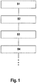
- FIG. 1 a schematic sequence of the method according to the invention is shown with the essential steps.
- a magnetically excitable core 24 having a substantially cuboidal shape 20 is provided, see also FIG. 2 ,
- the core 24 has on one side 28 parallel grooves 32.
- a core winding 40 has grooved wire portions 105 which are later disposed in the grooves 32.
- the groove wire sections 105 to be arranged in the grooves 32 and combined into a group are referred to as winding sides 36.
- the winding side 36 having core winding 40 is in a pressing tool 44 ( FIG. 6B ) so pressed that the winding sides 36 are deformed and thereby the contour of a groove 32 are adapted, step S2.
- the pressed core winding 40 is inserted with its winding sides 36 in the grooves 32 of the core 24, see also FIG. 8 .
- the core 24 together with the core winding 40 is formed into a cylindrical ring shape 52 with radially inwardly directed grooves 32.
- FIG. 2 a side view of the cuboid core 24 is shown.
- the core 24 has a cuboidal shape 20 with end faces 56 which are facing away from each other.
- the end faces 56 are connected to each other by a back surface 60 and a groove surface 64.
- the two end surfaces 56, the back surface 60 and the groove surface 64 define a rectangular core cross-section;
- the core 24 has two ends 61 each having an end surface 68.
- the core 24 has a total of thirty-six grooves 32, all of which are aligned parallel to each other and arranged in a common plane.
- the grooves 32 are all open in the same direction and terminate in groove openings 72, all of which lie in the groove surface 64.
- the grooves 32 are through Parallel flanked teeth 76 limited.
- the teeth 76 have a tooth tip 78 terminating in the groove surface 64 and a tooth root 80.
- the tooth roots 80 of the teeth 76 are all in a plane parallel to the dorsal surface 60.
- the teeth 76 have a cross-sectional or profile shape 82, so that the teeth 76 extend parallel to the end surfaces 68.
- Each tooth head 78 has two racks 84 see also FIG. 8 extending in the cylinder ring shape 52 bent core 24 in the circumferential direction.
- Each tooth 76 is constructed symmetrically to a tooth center plane 86 which is oriented parallel to the end surfaces 68.
- Thirty-five fully formed teeth 76 are disposed between the two half teeth 88 so that a total of thirty-six grooves 32 and in the rounded state of the core 24 thirty six teeth 76 result, with one tooth formed of two bisected teeth 88
- the entire teeth 76 and the half teeth 88 are integrally connected with their Zahnfuß 80 with a core spine 89 with each other.
- the core back forms a magnetic return of all the whole and half teeth 76 and 88.
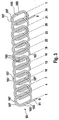
- the core winding 40 shown is a three-phase double-layered loop winding 90.
- the three-phase loop winding 90 wound from coated wire 91 consists of the first phase 93 with the connecting wires U and X, the second phase 96 with the core winding terminals V and Y and the third phase 99 the lead wires W and Z.
- the loop winding 90 is with its core winding terminal U in a groove 32 with a groove number. 1 inserted, the core winding lead wire Z is inserted into a groove 32 with a groove number 2 and the core winding lead wire V in a groove 32 with a groove number 3.
- this core winding 40 has a so-called total overwind 102, which is when inserting the core winding 40 in the Core 24 is initially not inserted in grooves 32.
- FIG. 3 is the first phase 93 from the FIG. 2 represented in a basically the same design.
- the first phase 93 like the other two phases, consists of slot wire sections 105 and connecting wires 107 connecting these respective slot wire sections 105.
- the numbers 1 to 34 shown below the illustration of the first phase 93 indicate which slot wire sections 105 in which slots with the slot number 1 to 34 or 1 come to rest or be inserted.
- FIG. 4 is a cross-sectional view of all three phases 93, 96 and 99 as shown in FIG. 2 are shown, but only by way of example, the first phase 93 is designated.
- the other two phases 96 and 99 are made analogously.
- the numbers 1 to 36 and 3 indicate the slot numbers.
- a groove wire section 105 is arranged in a position corresponding to the groove number 1, U1, in a first step from the end of the phase U.
- the connecting wire 107 not shown, connects, which extends to the position of the groove 32 with the groove number 4.
- the winding is continued with the grooved wire section 105, U2.
- FIG. 5 is fragmentary and enlarged the range of winding sides 36 shown, which are inserted into the grooves 32 with the groove numbers 34, 35 and 36, and the individual winding overhangs 115 of the three phases 93, 96 and 99.
- a distance d1 between a winding side 36 of second phase 96 and the winding side 36 of the third phase 99 corresponds to the distance between two grooves 32 in the parallelepiped state of the core 24, see also FIG. 2 .
- the distance between the winding side 36 of the third phase 99 and the individual and first winding overhang 115 of the first phase 93 is denoted by d2.
- This distance denotes the distance between the last winding side 36 to be inserted into the core 24 before the round bending and the first winding overhang 115 which can no longer be inserted into the flat core 24.
- the distance d2 is greater than the distance d1.
- the distance between the individual winding overhangs 115 of the three phases 93, 96 and 99 with each other corresponds to the distance d1.
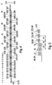
- FIG. 6A the cross section of a single winding side 36 is shown.
- the cross section of a single winding side 36 initially consists of the cross sections of individual groove wire sections 105, which are initially arranged more or less randomly within a certain envelope surface 118. Opposite the representation in the Figures 3 . 4 and 5 here more loops or turns have been wound.
- the winding sides 36 are deformed before insertion into the grooves 32 of the core 24 in a pressing tool so that the envelope surface 118 finally assumes the groove shape 119 of the pressing tool 44, see also FIG. 6B ,
- the winding side 36 is initially loose in the groove shape 119 of the pressing tool 44 according to the direction of the arrow in FIG. 6B inserted.
- a punch 120 presses the winding side 36 into the groove shape 119 and thereby forms the winding side 36 in such a plastic manner that it permanently assumes the groove shape 119 as the outermost envelope surface 118.
- the groove shape 119 of the pressing tool 44 may be made to correspond to the cross-sectional shape of the grooves 32 after bending.
- the groove shape 119 corresponds to the groove cross-sectional shape of the grooves 32 less at least a portion of the material thickness d iso an insulating layer 123, see also Figures 6C and 6D such as FIG. 8 ,
- the total winding overhang 102 is in the height of the second layer 112.
- the individual winding overhangs 115 have undersides which are later directed to the first layer 110. These undersides of the individual winding overhangs 115 are raised beyond the second layer 112 by the pressing in the pressing tool 44 and lie on a curve K which lies within the later diameter of the later round core 24.
- the core winding 40 After pressing and forming the winding sides 36 of the core winding 40, the core winding 40 is inserted with the winding sides 36 in the lined with the insulating material 123 grooves 32, FIG. 8 ,
- the preassembled module formed from the core 24, the insulating material 123 and the core winding 44, is converted in the next method step S4 into a cylindrical ring shape 52 with radially inwardly directed grooves 32. It starts with the half tooth 88, which borders on the groove 32 with the groove number 36.
- the half tooth 88 is relatively bent in a tool to the nearest tooth 76 between the grooves 32 with the groove numbers 35 and 36, so that the tooth heads 78 approach each other and the groove openings 72 are reduced in size.
- a back portion 140 between the half tooth 88 and the tooth 76 bent between the grooves 32 with the groove numbers 35 and 36 so that the angle between the tooth 76 and the back portion 140 is reduced the same applies to the half tooth 88.
- This forming process is continued so far until finally the tooth 76 between the Grooves 32 with the groove numbers 3 and 4 to the tooth 76 between the grooves 32 with the groove numbers 2 and 3 is bent.
- the three winding overhangs 115 of the three phases 93, 96 and 99 must be inserted into the grooves 32 with the groove numbers 3, 2 and 1.
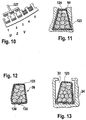
- the individual winding overhangs 115 are inserted or inserted respectively by means of a punch 126 into the grooves 32 with the groove numbers 3, 2 and 1.
- the already compressed core winding 40 or its winding sides 36 is folded before insertion into the core 24 on the sides with the insulating layer 123 and optionally stuck, which later lies in Nutground.
- the slot closure foil 124 is inserted into the grooves 32 as previously via the punches 126 and 127 equipped with slot closure foils 124 with the winding overhangs 115.
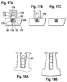
- Another variant provides for the pressed winding sides 36 to be placed in a groove 32 with a one-piece insulating layer 123 prior to insertion, FIG. 12 , In the embodiment shown therein, the insulating layer 123 is placed around the winding side 36 so that two ends 130 of the insulating layer 123 overlap and are glued together between the two adjacent surfaces of the ends.
- the entire core winding 40 is placed only after the wrapping of the winding sides 36 with the insulating layer 123 in the grooves 32 of the core 24, FIG. 13 ,
- FIG. 14 is a simple loop winding spatially represented.
- This loop winding in turn represents the first phase 93 of a core winding 40.
- This loop winding is wound starting from a position of a groove 32 having the groove number 1, so that a first loop is wound in the grooves 32 with the groove numbers 1 and 4 and finally in a relation to the Nutabriol three-step further coils are arranged.
- the first phase 93 ends with the end X in the groove 32 with the groove number 34.
- a correspondingly constructed second phase 96 is transferred to a groove 32 with the groove number 2 up to a groove 32 with the groove number 35 to form a core winding 40
- the same is done with a third phase 99, starting in the groove with the number 3 to the groove with the groove number 36.
- a core winding 40 constructed in this way has no overall development overhang 102.
- a core 24 is shown with seventy-two slots.
- a first phase 93 starting from a groove 32 with the groove number 1, in the grooves 1 and 7 wound to be wound around the grooves 2 and 8 after a certain number of turns.
- a coil connecting wire is used to wind another coil or into the slots 14 and 20 and so on, until finally, after a total of eight further coils, the phase winding 93 returns to the slot numbered 68 the wire is guided out of the core 24.
- the second phase 96 is started to finally lead in the groove with the number 70, the wire of the second phase 96 from the core 24 again.
- the winding of the third phase 99 starts in the groove with the number 5 and ends in the groove with the number 72.
- the first phase 93 is shown in the form of a distributed wave winding 135.
- the wire 91 is guided into the groove 4 via a connecting wire section 107, from there again via a further connecting wire section 107 into the groove 7 and, as in FIG. 16 shown, further wound until a first winding overhang 115 arises in a position corresponding to the groove 1. From there, the grooves 34 to 4 are wound back.
- a second phase winding 96 is wound in an analogous manner, starting from the groove 2 to the groove 2, and a winding overhang 115 formed there back to the groove 5, a third phase, starting in the groove 3, to a winding overhang 115 in the groove 32 with the groove number 3 and from there back into the groove 32 with the groove number 6 wound.
- a core 24 with a core winding 40 designed as a distributed wave winding 35 is also suitable for the method according to the invention.
- the core 24 is provided.
- the winding 40 is either wrapped with the wire 91 or inserted a prefabricated winding 40 in the grooves 32.
- the winding 40 is not yet pressed.
- a guide element 173 is placed on the later radially inwardly directed side 28 of the core 24 so that a constant distance is set between the guide elements 173.
- a forming die 176 with an inner contour 179 is then guided by the two guide elements 173 guided on the winding side 115.
- the individual grooved wire sections 105 of the winding side 115 are thereby forced into the inner contour 179 and reshaped so that the cross sections of the winding sides 115 after the forming corresponds to the cross section of a groove 32 after the round bending of the core 24, FIG. 17A, FIG. 17B ,
- an insulating layer 123 may be introduced beforehand as required.
- the forming punch 176 is removed again from the groove 32, the guide elements 173 are lifted off the core 24, Figure 17C ,
- This core 24 with winding 40 is then as in FIG. 9 or 10 shown and described in the further process steps processed.
- wire 91 whose largest cross-sectional dimension is greater than the width of the groove opening 72 in the circumferential direction of the core 24, if it is still in cuboid shape 20. If such a winding with an endless wire 91, for example, wire 91 having a rectangular wire cross section as used for windings called rod windings, wound, as is performed in the already described three winding designs, so inserting the core winding 40 is not possible per se , To remedy this, the core 24 is bent over its back surface 60 before inserting the core winding 40 so that the groove openings 72 expand and the core winding 40 can be inserted.
- the embodiment of the Figures 18A and 18B is not limited to the use of wires of the corresponding cross-sectional dimensions. Rather, this also applies to core windings 40 with winding sides 36, which are pressed so that they are not due to their width in the circumferential direction per se are not inserted into the groove opening 72, but only after the widening of the groove opening after bending the core 24 via its back surface 60th
- a so-called baked enamel can be used to fix the winding sides 36. This is for example possible because one already with such a paint treated wire 91 is used, the varnish layer in the pressing tool 44 heated and at least assumes a sticky state, so that the wires 91 can adhere to each other and are firmly bonded together after cooling and solidification and easy to continue processing.
- the electrically effective slot fill factor is defined here as the area cross section ratio of the sum of all cross sections arranged in a groove 32 of the electrically effective part of the slot wire sections 105 with respect to the cross section of the slot 32 after the round bend.
- the electrically effective Nuthelltex of at least 55%. This lower limit represents a minimum requirement for the electrical efficiency.
- An upper limit of 75% is technically just possible.
- a higher slot fill factor results in such high forces when pressing the winding sides 36 that a layer of paint on the wires 91 will be damaged, thus making short circuits in the core winding 40 unusable.
- a good compromise taking into account the manufacturing tolerances and technical feasibility is given with a groove fill factor in a range between 57% and 70%.
- a stator 150 is shown of a core 24 constructed of fins 153 with a simple loop winding as a core winding 40.
- a joint 156 formed from the two abutting end surfaces 68 of the round bent core 24, shown.
- a weld 160 is set at the joint 156 to connect both ends 61 of the core 24 firmly together.
- FIG. 20 a symbolic representation of an electric machine 140 with the stand 150 according to the invention is shown.
Description
Aus der
Zur Herstellung dieses Ständers werden zunächst einzelne Blechlamellen ausgestanzt und eine bestimmte Anzahl dieser Blechlamellen einander deckend bis zur gewünschten axialen Breite des Kerns geschichtet. Diese geschichteten Blechlamellen bilden den Ständerkern, der damit auf einer Seite für einen Ständer übliche zueinander parallel ausgerichtete Zähne und Nuten aufweist. Eine bereits vorgewickelte, als verteilte Wellenwicklung ausgeführte Kernwicklung liegt in etwa in ebener Form vor und wird in die Nuten des im wesentlichen flachen Kerns anschließend eingelegt. Die flache Baugruppe aus Kern und Kernwicklung weist einen sogenannten Wicklungsüberhang auf, das heißt jede einzelne von insgesamt drei Phasen hat eine Wicklungsseite, die zunächst nicht in Nuten eingelegt ist. Diese Baugruppe aus Kern und Kernwicklung wird anschließend so rund gebogen, daß ein üblicher hohlzylindrischer Ständer entsteht. Dabei müssen die überhängenden Wicklungsseiten vor der Fertigstellung des Ständers in die entsprechenden Nuten abschließend eingelegt werden.For the production of this stand, first individual laminations are punched out and a certain number of laminations are stacked one above the other to cover the desired axial width of the core. These layered laminations form the stator core, which thus has on one side for a stand usual parallel aligned teeth and grooves. An already pre-wound, designed as a distributed wave winding core winding is approximately in a flat shape and is then inserted into the grooves of the substantially flat core. The flat assembly of core and core winding has a so-called winding overhang, that is, each of a total of three phases has one Winding side, which is initially not inserted in grooves. This assembly of core and core winding is then bent around so that a conventional hollow cylindrical stator is formed. In this case, the overhanging sides of the winding must be finally inserted into the corresponding slots prior to the completion of the stand.
Durch seine Herstellung bedingt, weist der Kern zwei Enden auf, die beim Rundbiegen des Kern mit Kernwicklung bündig aneinander zu legen sind. Diese beiden Enden sind geometrisch in den Nutgrund einer Kernnut gelegt.Due to its production, the core has two ends which are flush with each other when bending the core with the core winding. These two ends are geometrically placed in the groove bottom of a core groove.
Bei diesem Stand der Technik ist nachteilig, daß trotz des guten Zugangs zu den Nuten der Füllungsgrad nicht optimal ist.In this prior art is disadvantageous that despite the good access to the grooves, the degree of filling is not optimal.
Der Erfindung liegt die Erkenntnis zu Grunde, daß die vor dem Rundbiegen des Lamellenpakets aufgeweiteten Nuten so zu füllen sind, daß die eingelegte Wicklung bereits vor dem Rundbiegen zumindest in etwa der Form der Nuten nach dem Rundbiegen entspricht, wobei eine gewisse Pressung innerhalb der eingelegten Wicklung durchaus erwünscht ist.The invention is based on the finding that the flared prior to the round bending of the laminated core grooves are to be filled so that the inserted winding already corresponds to the round bending at least approximately the shape of the grooves after the round bending, with a certain pressure within the inserted winding is quite desirable.
Die gestellte Aufgabe wird durch die Merkmale der unabhängigen Ansprüche 1 und 13 gelöst.The stated object is solved by the features of
Nach dem erfindungsgemäßen Verfahren zum Herstellen eines Kerns für eine elektrische Maschine ist deshalb vorgesehen, daß alle Wicklungsseiten der Kernwicklung, bevor sie in die Nuten des Kerns eingelegt werden, in einem Werkzeug in eine Nutform gepreßt und umgeformt werden. Dies ist eine sehr vorteilhafte Maßnahme, weil damit verhältnismäßig hohe Nutfüllfaktoren von 55 % und mehr erreicht werden. Es wird dadurch verhindert, daß die vormontierte Baugruppe aus flachem Kern und Kernwicklung beim Rundbiegen in die hohlzylindrische Form die Verformungsarbeit aufnehmen muß und dadurch der Kern unzulässig verformt wird.According to the method of manufacturing a core for an electric machine according to the invention, it is therefore provided that all the winding sides of the core winding before they are inserted into the grooves of the core are pressed into a groove shape in a tool and deformed. This is a very advantageous measure because relatively high slot fill factors of 55% and more are achieved. It is thereby prevented that the preassembled assembly of flat core and core winding when bending into the hollow cylindrical shape must absorb the deformation work and thereby the core is deformed unduly.
Durch die in den Unteransprüchen aufgeführten Maßnahmen ergeben sich vorteilhafte Weiterbildungen und Verbesserungen des Verfahrens nach dem Hauptanspruch.The measures listed in the dependent claims, advantageous refinements and improvements of the method according to the main claim.
In einer weiteren Ausgestaltung der Erfindung ist vorgesehen, daß an beiden, in einem späteren Schritt miteinander zu verbindenden Enden des Kerns jeweils in Umfangsrichtung ein halber Zahn ausgebildet wird, das heißt, daß die Stoßkanten des Lamellenpakets nicht wie bekannt in einer Nut liegen, sondern innerhalb eines die Nuten einrahmenden Zahns. Durch diese Maßnahme wird zwar das Verbinden der Stoßkanten erschwert, wird jedoch eine Spule mit Wicklungsüberhang in den Kern eingelegt, so muß dieser Wicklungsüberhang kurz vor dem Abschluß des Rundbiegens des Kerns beziehungsweise des Ständers in eine Nut eingelegt werden. Ist nun diese Nut bereits fertig gebildet, besteht keine Gefahr, daß diese Wicklungsseite des Wicklungsüberhangs zwischen den beiden Enden an den Stoßkanten eingeklemmt wird. Eine Zerstörung dieser letzten einzulegenden Wicklungsseite, insbesondere bei schnell laufendem Fertigungsprozeß, wird auf einfache Weise sicher verhindert. Außerdem wird vermieden, daß eine um die letzte einzulegende Wicklungsseite gelegte Nutisolation beim Einlegen der Wicklungsseite von dieser herunterrutscht und der Fertigungsprozeß dadurch zumindest nicht behindert wird. Ein weiterer Vorteil eines je halb ausgebildeten Zahns liegt darin, daß der magnetische Widerstand im magnetischen Rückschluß des Ständerkerns nicht unterbrochen ist und somit magnetische Verluste verringert sind.In a further embodiment of the invention it is provided that at both, to be joined together in a later step ends of the core in each case a half tooth is formed, that is, that the abutting edges of the disk set are not known to lie in a groove, but within a tooth framing the grooves. Although this measure makes it difficult to connect the abutting edges, however, if a coil with winding overhang is inserted into the core, then this winding overhang must be inserted into a groove shortly before the conclusion of the round bending of the core or of the stator. Now, if this groove is already formed, there is no risk that this winding side of the winding overhang is clamped between the two ends at the abutting edges. Destruction of this last winding page to be inserted, especially in fast-running manufacturing process is easily prevented safely. In addition, it is avoided that a groove insulation placed around the last winding side to be slipped when inserting the winding side of this and the manufacturing process is thereby at least not hindered. Another advantage of each half-formed tooth is that the magnetic resistance in the magnetic yoke of the stator core is not interrupted and thus magnetic losses are reduced.
Wird die Kernwicklung angefertigt, nehmen die einzelnen Spulen- oder Schleifenseiten einen Hüllraum ein, der in der Regel größer ist als der eigentliche Nutraum nach dem Rundbiegen des Kerns. Preßt man die Wicklungsseiten vor dem Einlegen in den Kern jeweils in eine Nutform eines Werkzeugs, die einer Endform der Nut des Kerns entspricht, werden die Wicklungsseiten verformt und der Hüllraum der Wicklungsseiten dem eigentlichen Nutraum nach dem Rundbiegen des Ständers beziehungsweise Kerns angepaßt. Es wird dadurch vermieden, daß beim Rundbiegen des Ständers, das heißt des Kerns mit der Kernwicklung, die einzelnen Zähne des Kerns auf die Wicklungsseiten Verformungskräfte ausüben und dadurch möglicherweise selbst verbogen werden, was den Kern möglicherweise zerstören würde. Berücksichtigt man bei der Nutform des Werkzeugs zumindest einen Anteil der Dicke einer Isolierschicht indem man die Nutform des Werkzeugs um einen solchen Anteil am Umfang der Nutform verkleinert, werden die Wicklungsseiten allenfalls durch die Isolierschicht zwischen zwei Zähnen leicht gepreßt. Die Wicklungsseiten beziehungsweise die Kernwicklung wird dadurch in ihrer Lage leicht dämpfend gehalten, mögliche Schwingungen der Wicklungsseiten gedämpft und ein Abscheuern einer Lackschicht auf den Spulendrähten und schließlich ein möglicher Kurzschluß vermieden. Insbesondere bei Berücksichtigung der ganzen Dicke der Isolierschicht, indem die Nutform des Werkzeugs um die ganze Dicke der Isolierschicht kleiner ist als die Nutform der Kernnuten, bleibt die Isolierschicht unbeschädigt.When the core winding is made, the individual coil or loop sides occupy an enveloping space, which in the Usually larger than the actual groove space after the round bending of the core. Pressing the winding sides before inserting into the core each in a groove shape of a tool corresponding to a final shape of the groove of the core, the winding sides are deformed and adapted the envelope of the winding sides of the actual groove space after the round bending of the stator or core. It is thereby avoided that during round bending of the stator, that is, the core with the core winding, the individual teeth of the core exert on the winding side deformation forces and thereby possibly even be bent, which would possibly destroy the core. Taking into account in the groove shape of the tool at least a portion of the thickness of an insulating layer by reducing the groove shape of the tool by such a proportion on the circumference of the groove shape, the winding sides are at best easily pressed through the insulating layer between two teeth. The winding sides or the core winding is thereby held in its position slightly dampening, damped possible vibrations of the winding sides and a scrubbing of a lacquer layer on the coil wires and finally avoided a possible short circuit. In particular, taking into account the entire thickness of the insulating layer in that the groove shape of the tool is smaller by the entire thickness of the insulating layer than the groove shape of the core grooves, the insulating layer remains undamaged.
Wickelt man eine Kernwicklung mit einem sogenannten Wicklungsüberhang, so erreicht man einen weitestgehend symmetrischen Aufbau beider Wickelköpfe auf beiden Seiten des Ständerkerns. Die Wickelköpfe haben dann insbesondere im Bereich der Stoßstelle keine in etwa keilförmige Aussparung, die eine Durchlaßöffnung darstellt und beim Durchströmen mit Luft zu einem höheren Geräuschniveau führen könnte. Der durch den Wicklungsüberhang erreichte symmetrische Aufbau der Wickelköpfe führt weiterhin dazu, daß der Biegewiderstand der Baugruppe, die aus dem Kern und der Kernwicklung gebildet ist, über die Länge beziehungsweise den Umfang des Ständers weitestgehend konstant ist. Die fertige und in eine Zylinderringform gebogene Baugruppe aus Kern und Kernwicklung weist dadurch eine besonders gute Rundheit auf.If you wind a core winding with a so-called winding overhang, you achieve a largely symmetrical structure of both winding heads on both sides of the stator core. The winding heads then have, in particular in the region of the joint no approximately wedge-shaped recess, which represents a passage opening and could lead to a higher noise level when flowing through air. The symmetrical structure achieved by the winding overhang The winding heads also leads to the fact that the bending resistance of the assembly, which is formed from the core and the core winding, over the length or the circumference of the stator is largely constant. The finished and bent into a cylindrical ring assembly of core and core winding thus has a particularly good roundness.
Weist die Kernwicklung zumindest eine überhängende Wicklungsseite auf, und ist der Abstand zwischen dieser zumindest einen überhängenden Wicklungsseite zur nächstliegenden nicht überhängenden Wicklüngsseite größer als der Abstand zwischen zwei benachbarten Nuten, so ist das Einführen der überhängenden Wicklungsseite vor dem Abschluß des Rundbiegens des Kerns in die erste Nut erleichtert, Zugbelastungen zwischen der überhängenden Wicklungsseite und der letzten sich in der letzten Nut befindenden Wicklungsseite werden vermieden. Hebt man die zumindest eine überhängende Wicklungsseite beim Pressen der Wicklungsseiten in die Nutform aus der Ebene heraus, die die nicht überhängenden Wicklungsseiten bestimmen, so wird beim Rundbiegen und schließlich Einlegen der überhängenden Spulen vermieden, daß die Wicklungsseiten mit dem Ende des Kerns kollidieren und möglicherweise beschädigt werden.If the core winding has at least one overhanging winding side, and if the distance between this at least one overhanging winding side to the next non-overhanging winding side is greater than the distance between two adjacent grooves, then insertion of the overhanging winding side is complete before the completion of the round bending of the core into the first Groove facilitates tensile loads between the overhanging winding side and the last winding side located in the last groove are avoided. If one lifts the at least one overhanging winding side out of the plane during pressing of the winding sides into the groove shape, which determine the nonoverhanging winding sides, it is avoided during round bending and finally insertion of the overhanging coils that the winding sides collide with the end of the core and possibly become damaged become.
Eine als zweischichtige Schleifenwicklung ausgeführte Kernwicklung hat den Vorteil, daß jede Schleife einer Phasenwicklung einerseits Drähte am Innenumfang und damit im Zahnkopfbereich aufweist und andererseits Drähte im Bereich des Nutgrunds hat. Da die Kühlung der Wickelköpfe in der Regel am Innenumfang besser ist als am Außenumfang, wird dadurch eine letztlich gleichmäßige Kühlung einer Schleife und damit auch einer ganzen Phasenwicklung erreicht. Damit ist nicht nur eine Phasenwicklung gleichmäßig gekühlt, sondern auch die ganze Kernwicklung. Jede einzelne Phasenwicklung kann auf die gleiche Last ausgelegt werden.A core winding designed as a two-layer loop winding has the advantage that each loop of a phase winding on the one hand has wires on the inner periphery and thus in the tooth tip region and on the other hand has wires in the region of the groove bottom. Since the cooling of the winding heads is usually better on the inner circumference than on the outer circumference, thereby an ultimately uniform cooling of a loop and thus a whole phase winding is achieved. This not only a phase winding is cooled evenly, but also the whole core development. Each individual phase winding can be designed for the same load.
Führt man die Kernwicklung als einfache einschichtige Schleifenwicklung aus, weist die Kernwicklung keine überhängenden Wicklungsseiten auf, sind beim Rundbiegen der Baugruppe aus Kern und Kernwicklung keine überhängenden Wicklungsseiten einzufügen und der Rundbiegeprozeß in die Ringzylinderform kann ohne überhängende Wicklungsseiten einfach und problemlos durchgeführt werden.If the core winding is designed as a simple single-layer loop winding, the core winding has no overhanging winding sides, no overhanging winding sides are to be inserted during the round bending of the core and core winding assembly, and the round bending process into the ring cylinder shape can be performed simply and without overhanging winding sides.
In einer weiteren Ausgestaltung der Erfindung ist vorgesehen, den zur Verfügung gestellten Kern vor dem Einlegen der Kernwicklung in die Nuten über seinen Kernrücken, das heißt über die nicht genutete Seite um einen gewissen Betrag vorzubiegen, so daß die Nutöffnungen zum Einlegen der Wicklungsseiten erweitert werden. Durch diesen Verfahrensschritt ist es möglich, bei sehr kleinen Nutöffnungen des noch flachen Kerns Wicklungen mit Wicklungsseiten, die breiter sind als die Nutöffnung, in den Kern einzulegen. Dies ermöglicht verhältnismäßig breite Ausführungen der Zahnköpfe und damit einen sehr guten Übergang des Magnetfeldes von einem Läufer auf den Kern zu verwirklichen, was den Wirkungsgrad erheblich verbessert. Durch diesen Verfahrensschritt ist es auch möglich Drähte zu verwenden deren kleinste Abmessung im Querschnitt größer ist als die Breite der Nutöffnung im noch flachen Zustand des Ständerkerns, sowie Drähte, die einen nicht-runden Querschnitt aufweisenIn a further embodiment of the invention, the kernel provided before inserting the core winding in the grooves on its core back, that is on the non-grooved side vorzubiegen by a certain amount, so that the groove openings are expanded for inserting the winding sides. By means of this method step, it is possible, with very small slot openings of the still flat core, to insert windings with winding sides, which are wider than the slot opening, into the core. This allows relatively wide versions of the tooth tips and thus to realize a very good transition of the magnetic field from a rotor to the core, which significantly improves the efficiency. By this method step, it is also possible to use wires whose smallest dimension in cross-section is greater than the width of the slot opening in the still flat state of the stator core, as well as wires which have a non-circular cross-section
Wird der Wicklungsüberhang vor dem Abschluß des Biegens des Kerns in die Zylinderringform in die zumindest eine Nut eingelegt und erst dann fertiggebogen, ist die Nutöffnung breiter als beim fertig gebogenen Kern, wodurch sich das Einlegen des Wicklungsüberhangs vereinfacht.If the winding overhang is inserted into the at least one groove before completion of the bending of the core into the cylindrical ring shape and only then finished, the groove opening is wider than the finished bent core, which simplifies the insertion of the winding overhang.
Damit sich der in die Zylinderringform gebogene Kern nicht mehr um den elastischen Anteil der Biegung zurückverformt, ist vorgesehen, die Enden des Kerns miteinander stoffschlüssig zu verbinden.So that the core, which is bent into the cylindrical ring shape, is no longer deformed back around the elastic portion of the bend, it is provided that the ends of the core are connected to one another in a material-locking manner.
Die Erfindung wird nachfolgend in Ausführungsbeispielen anhand der zugehörigen Zeichnungen näher erläutert. Es zeigen:
-
Figur 1 -
Figur 2 -
Figur 3 -
Figur 4Figur 3 -
Figur 5Figur 4 -
Figur 6A einen Querschnitt einer Wicklungsseite unmittelbar nach dem Wickeln, -
Figur 6B eine Wicklungsseite wie inFigur 6A in einem Preßwerkzeug nach einem Preßvorgang, -
Figur 6C und -
Figur 6D Details zur Kontur einer Schleifenseite nach dem Pressen, -
Figur 7 -
Figur 8 -
Figur 9Nuten 1 bis 3, -
Figur 10Figur 9Nuten 1 bis 3, -
Figur 11 -
Figur 12 -
Figur 13Figur 12 -
Figur 14 -
Figur 15 -
Figur 16 -
Figuren 17A, 17B und 17C ein weiteres Ausführungsbeispiel eines Fertigungsverfahrens, -
Figur 18A einen Ausschnitt eines Kerns mit aufgebogener Nut und einer eingelegten Wicklungsseite, -
Figur 18B einen Ausschnitt der Nut ausFigur 17A nach dem Rundbiegen des Kerns, -
Figur 19A einen Kern mit Kernwicklung nach dem Ende seiner Fertigung, -
Figur 19B einen Ausschnitt des Kerns mit Kernwicklung im Bereich der Fügestelle, -
Figur 20
-
FIG. 1 shows the procedure for the production of the core with core winding according to the invention, -
FIG. 2 a side view of a core in cuboid shape and a plan view of a core winding with the core winding terminals and their assignment to grooves of the core, -
FIG. 3 a spatial representation of a phase of a two-layer loop winding, -
FIG. 4 a schematic synopsis of all three phases of the core winding, formed from a two-layer loop winding according toFIG. 3 . -
FIG. 5 shows details of a winding overhang of the windingFIG. 4 . -
FIG. 6A a cross section of a winding side immediately after winding, -
FIG. 6B a winding side as inFIG. 6A in a press tool after a pressing operation, -
FIG. 6C and -
FIG. 6D Details of the contour of a loop side after pressing, -
FIG. 7 the winding overhang and its position to the non-overhanging next winding sides, -
FIG. 8 a cross section of a groove with an inserted winding side before bending, -
FIG. 9 a detail of a side view of the almost completely round bent core with an auxiliary device for pressing the overhanging coils in thegrooves 1 to 3, -
FIG. 10 a variant of the deviceFIG. 9 for pressing the overhanging coils into thegrooves 1 to 3, -
FIG. 11 a cross-sectional view of a groove after the round bending, -
FIG. 12 a further embodiment for insulating a winding side, -
FIG. 13 a section of a according toFIG. 12 insulated winding side in a groove, -
FIG. 14 a spatial view of a single phase of a simple single-layer loop winding, -
FIG. 15 a core winding in a cuboid core, formed from a three-phase single-layer simple loop winding, -
FIG. 16 a simple embodiment of a distributed wave winding, -
Figures 17A, 17B and 17C another embodiment of a manufacturing method, -
Figure 18A a section of a core with a bent groove and an inserted winding side, -
FIG. 18B a section of the grooveFigure 17A after the round bending of the core, -
Figure 19A a core with core winding after the end of its production, -
FIG. 19B a section of the core with core winding in the region of the joint, -
FIG. 20 an electrical machine with a core core according to the invention.
In
Eine Kernwicklung 40 hat Nutdrahtabschnitte 105, die später in den Nuten 32 angeordnet werden. Die in den Nuten 32 anzuordnenden und zu einer Gruppe zusammengefassten Nutdrahtabschnitte 105 werden als Wicklungsseiten 36 bezeichnet. Die Wicklungsseiten 36 aufweisende Kernwicklung 40 wird in einem Preßwerkzeug 44 (
A core winding 40 has grooved
In
Die ganzen Zähne 76 und die halben Zähne 88 sind mit ihrem Zahnfuß 80 mit einem Kernrücken 89 miteinander einstückig verbunden. Der Kernrücken bildet einen magnetischen Rückschluß aller ganzen und halben Zähne 76 und 88.The
Über dem Kern 24 ist die Kernwicklung 40 dargestellt, die gegenüber dem Kern 24 um 90 Grad in die Figurenebene eingeklappt dargestellt ist. Die in
In
In
In
In
Wird die Kernwicklung 40, wie in
Nach dem Pressen und Umformen der Wicklungsseiten 36 der Kernwicklung 40 wird die Kernwicklung 40 mit den Wicklungsseiten 36 in die mit dem Isolierstoff 123 ausgekleideten Nuten 32 eingelegt,
Die vormontierte Baugruppe, gebildet aus dem Kern 24, dem Isolierstoff 123 und der Kernwicklung 44, wird im nächsten Verfahrensschritt S4 in eine Zylinderringform 52 mit nach radial innen gerichteten Nuten 32 umgeformt. Begonnen wird dabei mit dem halben Zahn 88, der an die Nut 32 mit der Nutnummer 36 grenzt. Der halbe Zahn 88 wird in einem Werkzeug zum nächstgelegenen Zahn 76 zwischen den Nuten 32 mit den Nutnummern 35 und 36 relativ gebogen, so daß sich die Zahnköpfe 78 einander annähern und die Nutöffnungen 72 verkleinert werden. Dabei wird gleichzeitig ein Rückenabschnitt 140 zwischen dem halben Zahn 88 und dem Zahn 76 zwischen den Nuten 32 mit den Nutnummern 35 und 36 so gebogen, daß der Winkel zwischen dem Zahn 76 und dem Rückenabschnitt 140 verkleinert wird, gleiches gilt bezüglich dem halben Zahn 88. Dieser Umformvorgang wird so weit weitergeführt, bis schließlich der Zahn 76 zwischen den Nuten 32 mit den Nutnummern 3 und 4 zum Zahn 76 zwischen den Nuten 32 mit den Nutnummern 2 und 3 gebogen wird.The preassembled module, formed from the
Vor dem Abschließen des Rundbiegens des Kerns 24 müssen jedoch zunächst die drei Wicklungsüberhänge 115 der drei Phasen 93, 96 und 99 in die Nuten 32 mit den Nutnummern 3, 2 und 1 eingelegt werden. Dazu werden die einzelnen Wicklungsüberhänge 115 mittels jeweils einem Stempel 126 in die Nuten 32 mit den Nutnummern 3, 2 und 1 eingelegt beziehungsweise eingeschoben. Nach einer Variante ist dies für die Wicklungsüberhänge 115 auch mittels eines einzelnen Stempels 127 möglich, siehe auch
Anstelle des Auskleidens einer Nut 32 mit einer Isolierschicht 123 vor dem Einlegen einer verpreßten Wicklungsseite 36 und dem anschließenden Schließen der Nut mittels einer Nutverschlußfolie 124, siehe auch
In
In
In einem weiteren Ausführungsbeispiel wird zunächst der Kern 24 bereitgestellt. In die Nuten 32 wird die Wicklung 40 entweder mit dem Draht 91 eingewickelt oder eine vorgefertigte Wicklung 40 in die Nuten 32 eingelegt. Die Wicklung 40 ist dabei noch nicht gepresst. Anschließend wird mit Nutseiten 170 einer Nut 32 fluchtend jeweils ein Führungselement 173 auf die später nach radial innen gerichtete Seite 28 des Kerns 24 aufgesetzt, so daß zwischen den Führungselementen 173 ein konstanter Abstand eingestellt ist. Ein Formstempel 176 mit einer Innenkontur 179 wird anschließend durch die beiden Führungselemente 173 geführt auf die Wicklungsseite 115 bewegt. Die einzelnen Nutdrahtabschnitte 105 der Wicklungsseite 115 werden dabei in die Innenkontur 179 gezwängt und so umgeformt, daß die Querschnitte der Wicklungsseiten 115 nach dem Umformen dem Querschnitt einer Nut 32 nach dem Rundbiegen des Kerns 24 entspricht,
Alternativ ist es auch möglich, jeweils einzelne in je eine Nut 32 gewickelte Nutdrahtabschnitte 105 nacheinander zu verpressen.Alternatively, it is also possible in each case to press
Vor dem Einwickeln beziehungsweise Einlegen der Wicklung 40 kann je nach Erfordernis zuvor eine Isolierschicht 123 eingebracht sein.Before wrapping or inserting the winding 40, an insulating
Nach dem Umformen wird der Formstempel 176 wieder aus der Nut 32 entfernt, die Führungselemente 173 vom Kern 24 abgehoben,
Dieser Kern 24 mit Wicklung 40 wird anschließend wie in
In einem weiteren Ausführungsbeispiel ist vorgesehen, Draht 91 zu verwenden, dessen größte Querschnittsabmessung größer ist als die Breite der Nutöffnung 72 in Umfangsrichtung des Kerns 24, wenn er noch in Quaderform 20 vorliegt. Wird eine solche Wicklung mit einem endlosen Draht 91, beispielsweise Draht 91 mit rechteckigem Drahtquerschnitt wie er für als Stabwicklungen bezeichnete Wicklungen verwendet wird, gewickelt, wie es bei den bereits beschriebenen drei Wicklungsausführungen durchgeführt ist, so ist ein Einlegen der Kernwicklung 40 an sich nicht möglich. Um dem abzuhelfen, wird der Kern 24 über seine Rückenfläche 60 vor dem Einlegen der Kernwicklung 40 so gebogen, daß sich die Nutöffnungen 72 erweitern und die Kernwicklung 40 einlegbar ist. Ist die Kernwicklung 40 eingelegt, wird, wie bereits beschrieben, auch hier der Kern 24 mit der Kernwicklung 40 anschließend rundgebogen und die Nutöffnungen 72 weiter verengt, siehe
Gegenüber üblichen Stabwicklungen, die oftmals doppelt so viele geschweißte oder gelötete Schaltverbindungen wie Nuten 32 aufweisen, ist der Aufwand Schaltverbindungen herzustellen auf die Drahtenden U bis Z beschränkt.In a further embodiment, it is provided to use
Compared to conventional rod windings, which often have twice as many welded or soldered interconnections as
Das Ausführungsbeispiel nach den
Um eine Formstabilität der gepresseten Wicklungsseiten 36 zu verbessern, kann ein sogenannter Backlack zur Fixierung der Wicklungsseiten 36 verwendet werden. Dies ist beispielsweise dadurch möglich, daß ein bereits mit einem solchen Lack behandelter Draht 91 verwendet wird, dessen Lackschicht im Presswerkzeug 44 erwärmt und zumindest einen klebrig zähen Zustand annimmt, so daß die Drähte 91 aneinander haften können und nach dem Abkühlen und Erstarren fest miteinander verbunden sind und einfach weiter zu verarbeiten sind.In order to improve dimensional stability of the pressed winding
Der elektrisch wirksame Nutfüllfaktor wird hier definiert als das Flächenquerschnittsverhältnis der Summe aller in einer Nut 32 angeordneten Querschnitte des elektrisch wirksamen Teils der Nutdrahtabschnitte 105 bezogen auf den Querschnitt der Nut 32 nach dem Rundbiegen.
Im Rahmen der Erfindung ist vorgesehen, einen elektrisch wirksamen Nutfüllfaktor von mindestens 55% zu verwirklichen. Diese Untergrenze stellt für die elektrische Wirksamkeit ein Mindesterfordernis dar. Eine Obergrenze von 75% ist technisch gerade noch möglich. Ein höherer Nutfüllfaktor führt zu so hohen Kräften beim Pressen der Wicklungsseiten 36, daß eine Lackschicht auf den Drähten 91 beschädigt wird und so Kurzschlüsse in der Kernwicklung 40 diese unbrauchbar machen. Ein guter Kompromiss unter Berücksichtigung der Fertigungstoleranzen und technischer Machbarkeit ist bei einem Nutfüllfaktor in einem Bereich zwischen 57% und 70% gegeben.The electrically effective slot fill factor is defined here as the area cross section ratio of the sum of all cross sections arranged in a
In the context of the invention is intended to realize an electrically effective Nutfüllfaktor of at least 55%. This lower limit represents a minimum requirement for the electrical efficiency. An upper limit of 75% is technically just possible. A higher slot fill factor results in such high forces when pressing the winding
In
In
Claims (19)
- Method for producing a core (24) which can be excited magnetically and has a core winding (40) for an electrical machine, according to which, in a method step (S1), the one core (24) is produced which essentially has a cuboid shape (20) with slots (32) running parallel on one side and in whose slots (32), in a method step (S2), the winding sides (36) of the core winding (40) are inserted and then, in a method step (S3), the core (24) together with the core winding (40) is formed into a cylindrical annular shape (52) with slots (32) pointing radially inwards, characterized in that all the winding sides (36), which are inserted into a respective slot (32), are each pressed and formed in a tool (44) into a slot shape (119) before being inserted into the slot (32).
- Method according to Claim 1, characterized in that the core (24) is manufactured such that a half tooth (88) is formed in the circumferential direction on each of its ends (61) which are to be joined to one another.
- Method according to one of the preceding claims, characterized in that the winding sides (36) of the core winding (40) are pressed into a slot shape (119) which corresponds to the cross-sectional shape of the slots (32) and of the core (24).
- Method according to Claims 1 and 2, characterized in that the winding sides (36) of the core winding (40) are pressed into a slot shape (119) which corresponds to the cross-sectional shape of the slots (32) of the core (24) minus at least one element with the thickness (dISO) of an insulating layer (123).
- Method according to one of the preceding claims, characterized in that the core winding (40) is wound with at least one winding overhang (115).
- Method according to Claim 5, characterized in that the distance (d2) between an overhanging winding side (36) and an adjacent winding side (36) which is not overhanging is wound such that it is greater than the distance (d1) between two slots (32).
- Method according to Claim 6, characterized in that the pressing of the winding sides (36) into the slot shape (119) results in the at least one overhanging winding side (36) being permanently raised out of a plane formed by the winding sides (36) which are not overhanging.
- Method according to one of the preceding claims, characterized in that the core winding (40) is in the form of a two-layer lap winding.
- Method according to one of the preceding claims, characterized in that, before the insertion of the core winding (40) into the slots (32), the core back (89) of the core (24) is bent such that slot openings (72) are widened for insertion of the winding sides (36).
- Method according to one of the preceding Claims 1 to 4, characterized in that the core winding (40) is in the form of a single, single-layer lap winding.
- Method according to one of the preceding Claims 1 to 9, characterized in that a winding overhang (115) is inserted into the at least one slot (32) before completion of the process of bending the core (24) into the cylindrical annular shape (52).
- Method according to one of the preceding claims, characterized in that, once the core (24) has been bent into the cylindrical annular shape (52), the ends (61) are connected to one another by techniques such as welding, soldering or bonding.
- Method for producing a core (24) which can be excited magnetically and has a core winding (40) for an electrical machine, according to which, in a method step (S1), the one core (24) is produced which essentially has a cuboid shape (20) with slots (32) running parallel on one side and in whose slots (32), in a method step (S2), the winding sides (36) of the core winding (40) are inserted and then, in a method step (S3), the core (24) together with the core winding (40) is formed into a cylindrical annular shape (52) with slots (32) pointing radially inwards, characterized in that all the winding sides (36) which are each inserted into a slot (32) are each shaped by means of a die (176) once they have been inserted into the slot (32), such that all the winding sides are shaped overall such that their external contour corresponds to a slot (32) in the bent-around core (24).
- Core (24) which can be excited magnetically and has a core winding (40) for an electrical machine (140), produced according to one of the preceding claims.
- Core (24) which can be excited magnetically and has a core winding (40) for an electrical machine (140) according to Claim 14, characterized in that the core (24) has a joint (156) at which its two end surfaces (68) are connected to one another.
- Core (24) which can be excited magnetically and has a core winding (40) for an electrical machine (140) according to Claim 14 or 15, characterized in that the two ends (61) are connected to one another by techniques such as welding, soldering or bonding.
- Core (24) which can be excited magnetically and has a core winding (40) for an electrical machine (140) according to one of Claims 14 to 16, characterized in that at least one core winding connection is arranged on each of the two sides of the joint (156).
- Stator (150) for an electrical machine (140), which is a core (24) which is produced according to one of the preceding Claims 14 to 17, can be excited magnetically and has a core winding (40).
- Electrical machine (140), in particular a generator, having a stator (150) according to Claim 18.
Applications Claiming Priority (3)
| Application Number | Priority Date | Filing Date | Title |
|---|---|---|---|
| DE10002385 | 2000-01-20 | ||
| DE10002385 | 2000-01-20 | ||
| PCT/DE2001/000244 WO2001054254A1 (en) | 2000-01-20 | 2001-01-22 | Method for producing a magnetically excitable core comprising a core winding for an electric machine |
Publications (2)
| Publication Number | Publication Date |
|---|---|
| EP1171945A1 EP1171945A1 (en) | 2002-01-16 |
| EP1171945B1 true EP1171945B1 (en) | 2016-03-30 |
Family
ID=7628187
Family Applications (1)
| Application Number | Title | Priority Date | Filing Date |
|---|---|---|---|
| EP01907382.4A Expired - Lifetime EP1171945B1 (en) | 2000-01-20 | 2001-01-22 | Method for producing a magnetically excitable core comprising a core winding for an electric machine |
Country Status (13)
| Country | Link |
|---|---|
| US (1) | US7600311B2 (en) |
| EP (1) | EP1171945B1 (en) |
| JP (2) | JP5506125B2 (en) |
| KR (1) | KR100928160B1 (en) |
| CN (1) | CN100466421C (en) |
| AU (1) | AU768932B2 (en) |
| BR (1) | BRPI0104099B1 (en) |
| DE (1) | DE10190175D2 (en) |
| ES (1) | ES2578652T3 (en) |
| MX (1) | MXPA01009479A (en) |
| RU (1) | RU2267215C2 (en) |
| WO (1) | WO2001054254A1 (en) |
| ZA (1) | ZA200107650B (en) |
Families Citing this family (60)
| Publication number | Priority date | Publication date | Assignee | Title |
|---|---|---|---|---|
| DE10115186A1 (en) * | 2001-03-27 | 2002-10-24 | Rexroth Indramat Gmbh | Cooled primary or secondary part of an electric motor |
| GB2389717B (en) * | 2002-01-24 | 2004-07-28 | Visteon Global Tech Inc | Automotive alternator stator assembly and winding method |
| DE10245691A1 (en) * | 2002-09-30 | 2004-04-08 | Robert Bosch Gmbh | Stand for an electrical machine |
| DE10328956A1 (en) | 2003-06-27 | 2005-01-20 | Elmotec Statomat Vertriebs Gmbh | Method and device for introducing wave windings in rotor and stator lamination packages of electrical machines |
| DE10328955B4 (en) * | 2003-06-27 | 2008-07-24 | Elmotec Statomat Vertriebs Gmbh | Method and apparatus for forming wave windings for rotor and stator lamination packages of electrical machines |
| DE10329576A1 (en) * | 2003-06-30 | 2005-02-24 | Robert Bosch Gmbh | Method for producing a two-layer loop winding |
| DE10329572A1 (en) | 2003-06-30 | 2005-01-20 | Robert Bosch Gmbh | Process for producing an electromagnetically excitable core |
| JP2005124319A (en) * | 2003-10-17 | 2005-05-12 | Mitsubishi Electric Corp | Stator of rotary electric machine and its manufacturing method |
| DE10361857A1 (en) | 2003-12-30 | 2005-07-28 | Robert Bosch Gmbh | Method for producing a stand and stands produced therefrom |
| DE10361858A1 (en) | 2003-12-30 | 2005-07-28 | Robert Bosch Gmbh | Stand for an electric machine |
| US7081697B2 (en) * | 2004-06-16 | 2006-07-25 | Visteon Global Technologies, Inc. | Dynamoelectric machine stator core with mini caps |
| SE0401826D0 (en) | 2004-07-09 | 2004-07-09 | Trimble Ab | Method of preparing a winding for an n-phase motor |
| DE102004058659A1 (en) * | 2004-12-06 | 2006-06-22 | Robert Bosch Gmbh | Manufacturing device and method for producing an electromagnetic element for an electrical machine |
| DE102005048094A1 (en) * | 2005-09-30 | 2007-04-05 | Robert Bosch Gmbh | Electrical machine`s stator winding manufacturing method, involves driving chambers by embossing stamp and/or chamber base, so that coil conductors are aligned in parallel to each other in region of coil longitudinal sides |
| DE102005063271A1 (en) * | 2005-12-30 | 2007-07-19 | Robert Bosch Gmbh | Generator, in particular for motor vehicles |
| DE102006016249A1 (en) | 2006-03-31 | 2007-10-04 | Robert Bosch Gmbh | Stator for electrical machine, has grooves separated from each other by tooth, where ratio of mass of wires in groove to total mass of wire lies between specified values and groove slot width is equal to groove width |
| DE202006007619U1 (en) * | 2006-05-11 | 2007-09-13 | Dr. Fritz Faulhaber Gmbh & Co. Kg | Coreless coil |
| JP5040303B2 (en) * | 2006-12-28 | 2012-10-03 | 株式会社日立製作所 | Rotating electric machine |
| DE102008006641A1 (en) | 2007-01-29 | 2008-12-24 | Robert Bosch Gmbh | Electric machine with a stand, and method for producing an electric machine with a stand |
| DE102007034322A1 (en) | 2007-07-24 | 2009-01-29 | Robert Bosch Gmbh | Electrical machine's i.e. three-phase synchronous generator, stator multi-phase winding manufacturing method for motor vehicle, involves separately molding winding strand with coil sides of windings of set of winding strands |
| DE102007036313A1 (en) | 2007-07-31 | 2009-02-05 | Robert Bosch Gmbh | Method for producing a winding for the stator of an electrical machine |
| DE102007036263A1 (en) | 2007-08-02 | 2009-02-05 | Robert Bosch Gmbh | Electrical machine i.e. alternating current synchronous generator, manufacturing method for use in motor vehicle, involves moving coil heads of lower strand halves opposite to coil heads of upper strand halves around winding pitch |
| DE102007038527A1 (en) | 2007-08-16 | 2009-02-19 | Robert Bosch Gmbh | Stator manufacturing method for e.g. electric generator, in motor vehicle, involves piling multi-discs for disc packet, inserting multi-disc insulator and stator coil, and welding multi-discs for formation of fixed disc packet |
| US7876016B2 (en) * | 2007-11-15 | 2011-01-25 | Sundyne Corporation | Stator winding method and apparatus |
| JP4705949B2 (en) * | 2007-12-12 | 2011-06-22 | 本田技研工業株式会社 | Stator manufacturing method |
| DE102009055043A1 (en) | 2008-12-19 | 2010-06-24 | Robert Bosch Gmbh | Stator manufacturing method for three-phase generator of motor vehicle, involves inserting winding sides into each groove, and arranging poles at distance of electrical specific degree/phases relative to each other |
| CN102246398B (en) * | 2008-12-19 | 2014-09-24 | 罗伯特·博世有限公司 | Method for producing a distributed lap winding for polyphase systems |
| DE102009024230A1 (en) * | 2009-05-29 | 2010-12-02 | Robert Bosch Gmbh | Method for producing a stator winding of an electrical machine, in particular for producing an alternating current generator |
| DE102009024231A1 (en) | 2009-05-29 | 2010-12-09 | Robert Bosch Gmbh | Method for producing a stator winding of an electrical machine, in particular an AC generator |
| DE102010042369A1 (en) | 2010-10-13 | 2012-04-19 | Robert Bosch Gmbh | Electric machine i.e. three-phase alternate current generator, for motor car, has groove portion arranged radially outside beyond tooth portion of electromagnetic, symmetrically formed tooth, where tooth portion is limited by groove walls |
| DE102010053716A1 (en) | 2010-12-01 | 2012-06-06 | Robert Bosch Gmbh | Method for embossing coil sides of a stator winding |
| CN103548242B (en) * | 2010-12-01 | 2016-05-18 | 罗伯特·博世有限公司 | For the manufacture of the method for the stator winding of the motor of alternating current generator especially |
| WO2012081087A1 (en) * | 2010-12-14 | 2012-06-21 | 三菱電機株式会社 | Rotating electrical machine for vehicle, and method for manufacturing stator for use in rotating electrical machine |
| DE102011085654A1 (en) | 2011-11-03 | 2013-05-08 | Continental Automotive Gmbh | Method for producing a round stator and rolling device |
| US9467010B2 (en) | 2011-11-17 | 2016-10-11 | Remy Technologies, L.L.C. | Method of winding a stator core with a continuous conductor having a rectangular cross-section and a stator core |
| US8745847B2 (en) | 2011-11-17 | 2014-06-10 | Remy Technologies, L.L.C. | Method of P-forming a continuous conductor having a rectangular cross section and a stator including a stator winding formed from a P-formed conductor having a rectangular cross-section |
| US8789259B2 (en) | 2011-11-17 | 2014-07-29 | Remy Technologies, L.L.C. | Method of winding a stator core with a continuous conductor having a rectangular cross-section and a stator core |
| US9118225B2 (en) * | 2012-08-24 | 2015-08-25 | Caterpillar Inc. | Coil with twisted wires and stator assembly of a rotary electric machine |
| US20140208579A1 (en) * | 2013-01-30 | 2014-07-31 | Victory Industrial Corporation | Manufacturing Method of a Stator of an Alternator |
| DE102013212407A1 (en) | 2013-06-27 | 2014-12-31 | Robert Bosch Gmbh | Electric machine |
| DE102013214106A1 (en) * | 2013-07-18 | 2015-01-22 | Bayerische Motoren Werke Aktiengesellschaft | Method for producing a field winding for an electrical machine, exciter winding and electrical machine |
| DE102013222643A1 (en) * | 2013-11-07 | 2015-05-07 | Robert Bosch Gmbh | Flat package for the production of a stator |
| FR3020521B1 (en) * | 2014-04-29 | 2016-06-03 | Nicolas Langlard | ROTATING ELECTRIC MACHINE STATOR WITH OPTIMIZED WINDING |
| EP2963773B1 (en) * | 2014-07-01 | 2019-10-02 | Victory Industrial Corporation | Vehicle alternating-current generator |
| DE102014221938A1 (en) | 2014-10-28 | 2016-04-28 | Robert Bosch Gmbh | Electric machine with a slot insulation and method for its production |
| DE102014226319A1 (en) | 2014-12-17 | 2016-06-23 | Robert Bosch Gmbh | Device for insulating an electromagnetically excitable stator iron and semi-finished product for an electrical machine |
| DE102014226253A1 (en) | 2014-12-17 | 2016-06-23 | Robert Bosch Gmbh | Apparatus comprising an electromagnetically energizable core and an insulating layer and method of attaching an insulating layer to an electromagnetically energizable core |
| DE102014226526A1 (en) | 2014-12-19 | 2016-06-23 | Robert Bosch Gmbh | Device with an electromagnetically excitable core, in which an insulated winding is inserted, and method for insulating a winding |
| DE102015200415A1 (en) | 2015-01-14 | 2016-07-14 | Robert Bosch Gmbh | Stator of an electric machine and method of manufacturing the stator |
| JP6203785B2 (en) * | 2015-06-25 | 2017-09-27 | ファナック株式会社 | Electric motor having 8-shaped connecting coil and manufacturing method thereof |
| US10110080B2 (en) | 2015-11-30 | 2018-10-23 | Caterpillar Inc. | Coil and stator assembly of a rotary electric machine |
| DE102015225758A1 (en) | 2015-12-17 | 2017-06-22 | Robert Bosch Gmbh | Process for coating an electromagnetically excitable core |
| DE102016123068A1 (en) * | 2016-11-30 | 2018-05-30 | Dr. Ing. H.C. F. Porsche Aktiengesellschaft | Rotary electric machine and specially adapted method for producing such |
| DE102017209792B4 (en) | 2017-06-09 | 2023-10-05 | Fraunhofer-Gesellschaft zur Förderung der angewandten Forschung e.V. | Semi-finished product for an electrotechnical coil and method and device for producing the same |
| DE102017213151A1 (en) | 2017-07-31 | 2019-01-31 | Fraunhofer-Gesellschaft zur Förderung der angewandten Forschung e.V. | Electrotechnical coil and method and semifinished product for producing the same |
| DE102017213106A1 (en) | 2017-07-31 | 2019-01-31 | Fraunhofer-Gesellschaft zur Förderung der angewandten Forschung e.V. | Method and device for producing an electrotechnical coil |
| DE102018104844A1 (en) * | 2018-03-02 | 2019-09-05 | Aumann Espelkamp Gmbh | Method and device for producing an arrangement for a coil with a distributed coil winding of an electrodynamic machine, arrangement and coil |
| DE102019132683A1 (en) * | 2019-08-08 | 2021-02-11 | stoba e-Systems GmbH | Electric motor and stator with multiple grooves |
| FR3126567A1 (en) * | 2021-09-01 | 2023-03-03 | Valeo Equipements Electriques Moteur | METHOD FOR WINDING A STATOR OF A ROTATING ELECTRIC MACHINE WITH MULTI-SLOTS PER POLE AND PER PHASE |
| DE102022101619A1 (en) * | 2022-01-25 | 2023-07-27 | Schaeffler Technologies AG & Co. KG | Method of forming a wave winding and a wave winding formed by the method |
Family Cites Families (29)
| Publication number | Priority date | Publication date | Assignee | Title |
|---|---|---|---|---|
| US1756672A (en) | 1922-10-12 | 1930-04-29 | Allis Louis Co | Dynamo-electric machine |
| US2607816A (en) | 1947-01-29 | 1952-08-19 | Stewart Warner Corp | Electric motor |
| DE1002385C2 (en) | 1953-12-14 | 1957-07-18 | Siemens Ag | Signal box with electrical locks, in particular the track diagram signal box |
| DE2629532A1 (en) * | 1975-07-03 | 1977-01-27 | Sev Alternateurs | METHOD AND DEVICE FOR A STATOR OR ROTOR OF AN ELECTRIC ROTATING MACHINE |
| JPS5694939A (en) | 1979-12-28 | 1981-07-31 | Shibaura Eng Works Co Ltd | Rotor |
| JPS59103549A (en) | 1982-12-01 | 1984-06-15 | Hitachi Ltd | Method and device for inserting coil |
| JPS59122331A (en) * | 1982-12-27 | 1984-07-14 | Hitachi Ltd | Armature for rotary electric machine and manufacture thereof |
| DE3408394A1 (en) | 1984-03-08 | 1985-09-19 | Robert Bosch Gmbh, 70469 Stuttgart | Electrical generator, especially a dynamo for vehicles |
| JPS63161845A (en) | 1986-12-22 | 1988-07-05 | Nippon Denso Co Ltd | Coil inserting device |
| JPS63194543A (en) * | 1987-02-09 | 1988-08-11 | Hitachi Ltd | Stator of ac generator for vehicle and manufacture thereof |
| JPH01252141A (en) | 1988-03-31 | 1989-10-06 | Shibaura Eng Works Co Ltd | Electric motor |
| JPH03155346A (en) * | 1989-11-08 | 1991-07-03 | Toshiba Corp | Stator core of rotary electric machine |
| JP2888142B2 (en) | 1993-11-08 | 1999-05-10 | 三菱電機株式会社 | Rotary motor and method of manufacturing the same |
| JPH04100968A (en) * | 1990-08-07 | 1992-04-02 | Iwasaki Tsuneo | Apparatus for detecting joint of continuous cloth |
| US5212419A (en) * | 1992-01-10 | 1993-05-18 | Fisher Electric Motor Technology, Inc. | Lightweight high power electromotive device |
| US5382859A (en) * | 1992-09-01 | 1995-01-17 | Unique Mobility | Stator and method of constructing same for high power density electric motors and generators |
| JPH07222408A (en) | 1994-02-03 | 1995-08-18 | Nippon Steel Corp | Manufacture of armature or field magnet of motor |
| JPH08223840A (en) | 1995-02-17 | 1996-08-30 | Toyota Motor Corp | Coil wire and its manufacture |
| JP3346968B2 (en) | 1995-10-06 | 2002-11-18 | 三菱電機株式会社 | Method of manufacturing stator for AC rotating electric machine |
| JPH09149608A (en) * | 1995-11-20 | 1997-06-06 | Toyota Motor Corp | Conductor bundle forming apparatus |
| JPH09168261A (en) * | 1995-12-14 | 1997-06-24 | Hitachi Ltd | Method and machine for manufacturing coil |
| JP3722539B2 (en) * | 1996-02-09 | 2005-11-30 | 黒田精工株式会社 | Manufacturing method of annular laminated iron core and progressive mold apparatus |
| US5946796A (en) * | 1996-11-15 | 1999-09-07 | Labinal Components & Systems, Inc. | Stator wire forming tool |
| JP3514939B2 (en) * | 1997-03-27 | 2004-04-05 | 株式会社日立製作所 | Method for manufacturing electric motor and stator |
| JPH10285882A (en) * | 1997-04-09 | 1998-10-23 | Hitachi Ltd | Manufacture of insulated coil and electric machine and rotary electric machine |
| FI112412B (en) * | 1997-04-18 | 2003-11-28 | Kone Corp | Process for producing the winding of an electric machine |
| JP3738528B2 (en) * | 1997-06-19 | 2006-01-25 | 株式会社デンソー | Stator for rotating electrical machine and method for manufacturing the same |
| JPH1132457A (en) * | 1997-07-10 | 1999-02-02 | Toyota Motor Corp | Stator for rotary electric machine |
| JP3735197B2 (en) * | 1998-02-27 | 2006-01-18 | 株式会社日立製作所 | Method for manufacturing coil molded body and mold used therefor |
-
2001
- 2001-01-22 WO PCT/DE2001/000244 patent/WO2001054254A1/en active Application Filing
- 2001-01-22 KR KR1020017011794A patent/KR100928160B1/en active IP Right Grant
- 2001-01-22 EP EP01907382.4A patent/EP1171945B1/en not_active Expired - Lifetime
- 2001-01-22 JP JP2001553641A patent/JP5506125B2/en not_active Expired - Fee Related
- 2001-01-22 ES ES01907382.4T patent/ES2578652T3/en not_active Expired - Lifetime
- 2001-01-22 MX MXPA01009479A patent/MXPA01009479A/en active IP Right Grant
- 2001-01-22 US US09/937,167 patent/US7600311B2/en not_active Expired - Fee Related
- 2001-01-22 CN CNB018000886A patent/CN100466421C/en not_active Expired - Fee Related
- 2001-01-22 AU AU35351/01A patent/AU768932B2/en not_active Ceased
- 2001-01-22 RU RU2001126556/11A patent/RU2267215C2/en not_active IP Right Cessation
- 2001-01-22 DE DE10190175T patent/DE10190175D2/en not_active Expired - Lifetime
- 2001-01-22 BR BRPI0104099A patent/BRPI0104099B1/en not_active IP Right Cessation
- 2001-09-17 ZA ZA200107650A patent/ZA200107650B/en unknown
-
2012
- 2012-06-11 JP JP2012132123A patent/JP5599432B2/en not_active Expired - Fee Related
Also Published As
| Publication number | Publication date |
|---|---|
| JP5506125B2 (en) | 2014-05-28 |
| WO2001054254A1 (en) | 2001-07-26 |
| MXPA01009479A (en) | 2002-06-04 |
| ES2578652T3 (en) | 2016-07-29 |
| RU2267215C2 (en) | 2005-12-27 |
| CN1358345A (en) | 2002-07-10 |
| US7600311B2 (en) | 2009-10-13 |
| EP1171945A1 (en) | 2002-01-16 |
| KR100928160B1 (en) | 2009-11-25 |
| JP5599432B2 (en) | 2014-10-01 |
| BRPI0104099B1 (en) | 2016-03-08 |
| ZA200107650B (en) | 2002-12-17 |
| CN100466421C (en) | 2009-03-04 |
| JP2003520559A (en) | 2003-07-02 |
| DE10190175D2 (en) | 2002-05-29 |
| AU3535101A (en) | 2001-07-31 |
| BR0104099A (en) | 2001-12-26 |
| AU768932B2 (en) | 2004-01-08 |
| KR20020002405A (en) | 2002-01-09 |
| US20030071534A1 (en) | 2003-04-17 |
| JP2012196133A (en) | 2012-10-11 |
Similar Documents
| Publication | Publication Date | Title |
|---|---|---|
| EP1171945B1 (en) | Method for producing a magnetically excitable core comprising a core winding for an electric machine | |
| DE10321221B4 (en) | Manufacturing method of a stator core for a dynamoelectric machine | |
| DE60210572T2 (en) | Winding for a rotary electric machine, method for producing this winding, and method for producing a rotary electric machine with such winding | |
| DE102012201698A1 (en) | Coil, stator and method of making the coil | |
| DE19851363A1 (en) | Method of manufacturing a stator for an electric motor | |
| DE3803752A1 (en) | STAND FOR A MOTOR VEHICLE THREE-PHASE GENERATOR AND MANUFACTURING METHOD THEREFOR | |
| DE4031276A1 (en) | STAND FOR ELECTRICAL MACHINES AND METHOD FOR THE PRODUCTION THEREOF | |
| DE102011008092A1 (en) | Stand for an electric motor | |
| EP1586155B1 (en) | Laminated stator core | |
| EP1494338B1 (en) | Manufacturing method for a core of an electic machine | |
| DE4122076A1 (en) | METHOD FOR PRODUCING A STATOR WINDING WITH PROFILE LADDERS FOR ELECTRICAL MACHINES | |
| EP1494337B1 (en) | Method for manufacturing a two layers winding | |
| EP1638186A1 (en) | Stator for an electric machine and Method for manufacturing it | |
| WO2018041836A1 (en) | Method for producing and inserting a wire winding | |
| EP1087497B1 (en) | Stator for an inner rotor motor | |
| DE102016207944A1 (en) | Package system for an electric machine, electric machine and method of manufacturing the package system | |
| DE102010043976A1 (en) | Component for manufacturing machine component e.g. stator for electric machine, has several teeth which are arranged at base portion in arrangement direction, and base portion comprises one or more upsetting regions between each teeth | |
| DE10239730A1 (en) | Multiphase stator winding for electrical machines with rotating magnetic fields, has grooves containing longitudinal conductors with overlapping end portions | |
| EP1915812B1 (en) | Electric machine with a multi-level winding | |
| WO2015000639A2 (en) | Machine component for an electric machine with multiple coils | |
| EP3167540B1 (en) | Method for producing an electrical machine using pre-formed coils and electrical machine and production tool | |
| DE4244694C2 (en) | Method for manufacturing a multi-phase electrical machine | |
| DE10121043A1 (en) | Manufacturing method for annular electromagnetic element for rotary electrical machine, winding toothed slot crown with coil wires before combining with yoke | |
| DE3638540C2 (en) | ||
| DE102021124996A1 (en) | Method of manufacturing a winding for a stator of a rotary electric machine, stator, method of manufacturing the stator and electric rotary machine |
Legal Events
| Date | Code | Title | Description |
|---|---|---|---|
| PUAI | Public reference made under article 153(3) epc to a published international application that has entered the european phase |
Free format text: ORIGINAL CODE: 0009012 |
|
| AK | Designated contracting states |
Kind code of ref document: A1 Designated state(s): AT BE CH CY DE DK ES FI FR GB GR IE IT LI LU MC NL PT SE TR |
|
| AX | Request for extension of the european patent |
Free format text: AL;LT;LV;MK;RO;SI |
|
| 17P | Request for examination filed |
Effective date: 20020128 |
|
| RBV | Designated contracting states (corrected) |
Designated state(s): DE ES FR GB IT SE |
|
| 17Q | First examination report despatched |
Effective date: 20090610 |
|
| GRAP | Despatch of communication of intention to grant a patent |
Free format text: ORIGINAL CODE: EPIDOSNIGR1 |
|
| INTG | Intention to grant announced |
Effective date: 20150907 |
|
| GRAS | Grant fee paid |
Free format text: ORIGINAL CODE: EPIDOSNIGR3 |
|
| GRAA | (expected) grant |
Free format text: ORIGINAL CODE: 0009210 |
|
| AK | Designated contracting states |
Kind code of ref document: B1 Designated state(s): DE ES FR GB IT SE |
|
| REG | Reference to a national code |
Ref country code: GB Ref legal event code: FG4D Free format text: NOT ENGLISH |
|
| REG | Reference to a national code |
Ref country code: DE Ref legal event code: R081 Ref document number: 50116544 Country of ref document: DE Owner name: SEG AUTOMOTIVE GERMANY GMBH, DE Free format text: FORMER OWNER: ROBERT BOSCH GMBH, 70469 STUTTGART, DE |
|
| REG | Reference to a national code |
Ref country code: DE Ref legal event code: R096 Ref document number: 50116544 Country of ref document: DE |
|
| REG | Reference to a national code |
Ref country code: ES Ref legal event code: FG2A Ref document number: 2578652 Country of ref document: ES Kind code of ref document: T3 Effective date: 20160729 |
|
| PG25 | Lapsed in a contracting state [announced via postgrant information from national office to epo] |
Ref country code: SE Free format text: LAPSE BECAUSE OF FAILURE TO SUBMIT A TRANSLATION OF THE DESCRIPTION OR TO PAY THE FEE WITHIN THE PRESCRIBED TIME-LIMIT Effective date: 20160330 |
|
| REG | Reference to a national code |
Ref country code: DE Ref legal event code: R097 Ref document number: 50116544 Country of ref document: DE |
|
| REG | Reference to a national code |
Ref country code: FR Ref legal event code: PLFP Year of fee payment: 17 |
|
| PLBE | No opposition filed within time limit |
Free format text: ORIGINAL CODE: 0009261 |
|
| STAA | Information on the status of an ep patent application or granted ep patent |
Free format text: STATUS: NO OPPOSITION FILED WITHIN TIME LIMIT |
|
| 26N | No opposition filed |
Effective date: 20170103 |
|
| PGFP | Annual fee paid to national office [announced via postgrant information from national office to epo] |
Ref country code: GB Payment date: 20170125 Year of fee payment: 17 |
|
| REG | Reference to a national code |
Ref country code: DE Ref legal event code: R081 Ref document number: 50116544 Country of ref document: DE Owner name: SEG AUTOMOTIVE GERMANY GMBH, DE Free format text: FORMER OWNER: ROBERT BOSCH GMBH, 70469 STUTTGART, DE |
|
| REG | Reference to a national code |
Ref country code: FR Ref legal event code: PLFP Year of fee payment: 18 |
|
| REG | Reference to a national code |
Ref country code: ES Ref legal event code: PC2A Owner name: SEG AUTOMOTIVE GERMANY GMBH Effective date: 20180119 |
|
| REG | Reference to a national code |
Ref country code: FR Ref legal event code: TP Owner name: SEG AUTOMOTIVE GERMANY GMBH, DE Effective date: 20180315 |
|
| GBPC | Gb: european patent ceased through non-payment of renewal fee |
Effective date: 20180122 |
|
| PG25 | Lapsed in a contracting state [announced via postgrant information from national office to epo] |
Ref country code: GB Free format text: LAPSE BECAUSE OF NON-PAYMENT OF DUE FEES Effective date: 20180122 |
|
| PGFP | Annual fee paid to national office [announced via postgrant information from national office to epo] |
Ref country code: IT Payment date: 20190121 Year of fee payment: 19 Ref country code: ES Payment date: 20190205 Year of fee payment: 19 Ref country code: FR Payment date: 20190117 Year of fee payment: 19 Ref country code: DE Payment date: 20190128 Year of fee payment: 19 |
|
| REG | Reference to a national code |
Ref country code: DE Ref legal event code: R119 Ref document number: 50116544 Country of ref document: DE |
|
| PG25 | Lapsed in a contracting state [announced via postgrant information from national office to epo] |
Ref country code: DE Free format text: LAPSE BECAUSE OF NON-PAYMENT OF DUE FEES Effective date: 20200801 |
|
| PG25 | Lapsed in a contracting state [announced via postgrant information from national office to epo] |
Ref country code: IT Free format text: LAPSE BECAUSE OF NON-PAYMENT OF DUE FEES Effective date: 20200122 |
|
| REG | Reference to a national code |
Ref country code: ES Ref legal event code: FD2A Effective date: 20210604 |
|
| PG25 | Lapsed in a contracting state [announced via postgrant information from national office to epo] |
Ref country code: FR Free format text: LAPSE BECAUSE OF NON-PAYMENT OF DUE FEES Effective date: 20200131 |
|
| PG25 | Lapsed in a contracting state [announced via postgrant information from national office to epo] |
Ref country code: ES Free format text: LAPSE BECAUSE OF NON-PAYMENT OF DUE FEES Effective date: 20200123 |