EP1167631B1 - Appareil de nettoyage de sol mobile - Google Patents
Appareil de nettoyage de sol mobile Download PDFInfo
- Publication number
- EP1167631B1 EP1167631B1 EP01113629A EP01113629A EP1167631B1 EP 1167631 B1 EP1167631 B1 EP 1167631B1 EP 01113629 A EP01113629 A EP 01113629A EP 01113629 A EP01113629 A EP 01113629A EP 1167631 B1 EP1167631 B1 EP 1167631B1
- Authority
- EP
- European Patent Office
- Prior art keywords
- wall
- dirt
- suction
- angle
- side walls
- Prior art date
- Legal status (The legal status is an assumption and is not a legal conclusion. Google has not performed a legal analysis and makes no representation as to the accuracy of the status listed.)
- Expired - Lifetime
Links
Images


Classifications
-
- E—FIXED CONSTRUCTIONS
- E01—CONSTRUCTION OF ROADS, RAILWAYS, OR BRIDGES
- E01H—STREET CLEANING; CLEANING OF PERMANENT WAYS; CLEANING BEACHES; DISPERSING OR PREVENTING FOG IN GENERAL CLEANING STREET OR RAILWAY FURNITURE OR TUNNEL WALLS
- E01H1/00—Removing undesirable matter from roads or like surfaces, with or without moistening of the surface
- E01H1/08—Pneumatically dislodging or taking-up undesirable matter or small objects; Drying by heat only or by streams of gas; Cleaning by projecting abrasive particles
- E01H1/0863—Apparatus loosening or removing the dirt by blowing and subsequently dislodging it at least partially by suction ; Combined suction and blowing nozzles
- E01H1/0872—Apparatus loosening or removing the dirt by blowing and subsequently dislodging it at least partially by suction ; Combined suction and blowing nozzles with mechanical loosening or feeding instruments for the dirt to be removed pneumatically, e.g. brushes, scrapers
Definitions
- the invention relates to a mobile floor cleaning device with a dirt suction device, which receives with its outer end dirt from the floor to be cleaned, with a dirt collecting container with which the inner end of the Schmutzaufsaug noise is in communication, and with a filter assembly through which the dirt in the dirt collecting air got out of this outlet, wherein the Schmutzaufsaug resonance has a suction line and a return line, is returned by the air from the dirt collector adjacent to and in the sweeping direction behind the outer end of the suction line to the floor to be cleaned, and wherein the outer ends of the suction line and return line lead into a suction mouth, the side walls diverge in the sweeping forward and at the rear end form a curved end wall, from the lower edge of which a bottom wall extends forward, the upper surface under a Wi nkel falls forward and ends in an arcuate leading edge.
- a known floor cleaning device CH 613 735 A
- two nozzle rings are present, which form an inner and an outer air jet.
- the inner air jet is used to remove the dirt from the soil to be cleaned, while the outer air jet is to prevent the Austriit of fine dust into the environment.
- a floor cleaning device of the type mentioned is inventively designed such that the side walls of the suction mouth with an opening angle of 30 ° to 50 °, in particular 34 ° to 46 °, diverge that the upper surface of the bottom wall at an angle of 5 ° to 15 °, in particular 7 ° to 13 °, falls forward, that at a distance in front of the front edge of the bottom wall an arcuate curved , is provided forwardly downwardly inclined, passing into the side walls intermediate wall which separates the outer ends of the suction line and return line and whose lower edge between them and the front edge of the bottom wall forms a remindlessnesssspalt forming above the front edge of the bottom wall that the curved rear wall portion of the intermediate wall is inclined to the horizontal at an angle of 60 ° to 80 °, in particular 66 ° to 73 °, and the inclination changes forward so continuously that the side wall portions of the intermediate wall are steeper inclined, and that the bottom wall in the region of the side wall inwards projecting portions
- the curved end wall in the planes of the bisector of the opening angle of the side walls of the bottom wall upwards at an angle of 45 ° to 70 °, in particular 48 ° to 61 °, inclined to the horizontal to the rear.
- the return line and the suction line which is usually parallel to this can have the same inclination in the area of the suction mouth.
- the lower edges of the side wall portions of the intermediate wall diverge in the sweeping forward with an opening angle of 55 ° to 75 °, in particular 59 ° to 68 °, and these side wall portions can merge at the front end of the inwardly projecting portions in the side walls of the suction mouth.
- the forward ends of the inwardly projecting portions may be spaced from the forward end of the respective associated side wall which is 20% to 40% of the distance of that forward end from the center of the end wall.
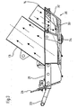
- FIG. 1 schematically shown mobile cleaning device is a articulated vehicle, the front, supported on front wheels (only the front wheel 4) supported platform 1 via a Doppelpendelgelenkan extract 10 with a rear platform is coupled, which rests on rear wheels 6, 7 and on which the largest part of the cleaning system 11 is arranged.
- a suitable Doppelpendelgelenkan extract is in the DE-A-100 29 691 described.
- the cleaning system 11 includes a dirt collecting container, not shown, which is closed by a filter assembly 13 to the environment and having a suction fan 12 which generates a negative pressure during operation and so on an obliquely from the upper part of the rear platform 2 below the front platform extending suction pipe in the region of a yet to be described, provided at the lower end of the suction pipe 13 suction 20 generates a suction air to absorb dirt from the ground to be cleaned, which are partially transported by conventional side brush (only one side brush 9) in the opening portion of the suction mouth 20 can.
- Parallel to the suction pipe 13 extends at the rear in the sweeping direction of this a return pipe 14, which opens at its lower end in a manner also to be described in the suction port 20 and the upper end in the upper part of the dirt collecting container or in an area above this dirt collector extends.
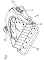
- the suction mouth 20 has a support plate 21, on the front side of a Abweisbügel 23 and at the rear region support rollers 24 and 25 are attached, which hold the suction mouth in operation at a predetermined height above the floor to be cleaned.
- a support plate 21 At the front of the support plate 21 is an elastically deformable, divided by incision into individual flap areas protective wall 26 is present, which allows one hand to be received dirt particles to a certain size and on the other hand prevents too large parts get into the suction area.
- a molded part is fixed, the side walls 30 and 31, the forward at an angle ⁇ of 30 ° to 50 °, preferably 34 ° to 46 °, diverge, ie extend to the front, while they go back into a the rear end of the molding forming, curved end wall 32.
- This curved end wall is inclined at an angle ⁇ of about 45 ° to 70 °, preferably 48 ° to 61 ° to the horizontal, and to it a bottom wall 33 connects, which extends from the end wall 32 to the front and in the subsequent region of the Side walls 30, 31 inwardly projecting portions 36, 37 has.
- the front ends of the sections 36, 37 are spaced from the front end of the respective side wall 30, 31, which is about 20% to 40% of the distance of this front end from the center of the end wall 32.
- the upper surface 35 of the bottom wall drops from the back to the front at an angle ⁇ of 5 ° to 15 °, preferably 7 ° to 13 °, to the horizontal, and also the sections 36 and 37 have a corresponding inclination from the side walls 30, 31 inside and down.
- an intermediate wall is formed, the side wall portions 38 and 39 which pass approximately at the front end of the inwardly projecting portions 36 and 37 of the bottom wall in the side walls 30 and 31 and which form a curved rear partition wall portion 40.
- This is inclined to the horizontal at an angle ⁇ of 60 ° to 80 °, preferably 66 ° to 73 °.
- the top edges of the side wall portions 38 and 39 of the intermediate wall diverge forward at an angle ⁇ of 50 ° to 70 °, while their bottom edges diverge at an angle of about 55 ° to 75 °, preferably 59 ° to 68 °. Their steepness increases compared to that of the rear partition wall portion 40 continuously.
- FIG. 3 shows, opens the lower end of the suction tube 13 in the area immediately before the end portion 40 of the intermediate wall in the molding, including in the support plate 21 of the suction mouth 20 a in FIG. 4 recognizable opening is formed.
- the lower end of the return pipe 14 opens into the molding in the region between the end wall 32 and the end wall portion 40 of the intermediate wall, ie, the intermediate wall separates the outer ends of suction line 13 and return line 14.
- the inclination of the return line 14 to the horizontal and thus also the inclination of the suction line 13 is equal to the inclination of the end wall 32nd
- larger dirt particles are separated from the air flow in a conventional manner by an uncritical coarse filter and fall into the dirt collecting, while loaded with fine dust air flows through the filter assembly 13 'in the environment, wherein the particulate matter contained in it is retained in the filter assembly ,
- a portion of the conveyed through the suction pipe 13 air is passed through the return line 14 in the manner described in the area in front of the intermediate wall 38, 39, 40 and between the side walls 30, 31 on the floor to be cleaned and supports the detachment and stirring up of dirt - And dust particles, which are removed by means of the suction air flow through the suction pipe 13.
- the volume flow of the return air flow increases when the permeability of the filter assembly 13 'due to particulate matter decreases.
- the suction air can act with a volume flow of 0.77 m 3 / s at an air flow speed of 33 m / s and the return air with a volume flow of 0.17 m 3 / s and an air flow speed of 23 m / s are directed to the floor to be cleaned.
- a load of the filter of about 80% ie a reduction of its air permeability to 20%, leads to a reduction of the suction air to a flow rate of 0.33 m 3 / s at an air flow rate of 14 m / s, while the return air is on a Volume flow of 0.22 m 3 / s increased at an air flow rate of 31 m / s.
- the floor cleaning device in question can work effectively without cleaning the filter assembly. Only with further increase in the filter load, it makes sense to interrupt the cleaning operation and to make the filter assembly fully functional again by tapping the accumulated particulate matter, although it has been shown that even with further increased filter load still a useful operation is achieved.
Landscapes
- Engineering & Computer Science (AREA)
- Architecture (AREA)
- Civil Engineering (AREA)
- Structural Engineering (AREA)
- Cleaning In General (AREA)
- Vehicle Cleaning, Maintenance, Repair, Refitting, And Outriggers (AREA)
- Electric Suction Cleaners (AREA)
Claims (6)
- Appareil roulant de nettoyage du sol, comprenant un équipement d'aspiration de saleté qui ramasse par son extrémité extérieure la saleté sur le sol à nettoyer, un bac collecteur de saleté avec lequel communique l'extrémité intérieure du dispositif d'aspiration de saleté, et un arrangement de filtres (13') à travers lequel l'air entré dans le bac collecteur de saleté par l'intermédiaire de l'équipement d'aspiration de saleté sort dudit bac, dans lequel l'équipement d'aspiration de saleté présente une conduite d'aspiration (13) et une conduite de recyclage (14) à travers laquelle de l'air provenant du bac collecteur de saleté est ramené sur le sol à nettoyer, à côté de l'extrémité extérieure de la conduite d'aspiration (13), et dans la direction de balayage derrière celle-ci, et dans lequel les extrémités extérieures de la conduite d'aspiration (13) et de la conduite de recyclage (14) débouchent sur un orifice d'aspiration (20) dont les parois latérales (30, 31) divergent vers l'avant dans la direction de balayage et forment à l'extrémité arrière une paroi terminale courbe (32) à partir du bord inférieur de laquelle s'étend une paroi de fond (33) vers l'avant dont la surface supérieure descend vers l'avant sous un angle (α) et se termine par une arête avant en forme d'arc (34),
caractérisé en ce que- les parois latérales (30, 31) de l'orifice d'aspiration (20) divergent sous un angle d'ouverture (ε) de 30° à 50°, en particulier de 34° à 46°,- la surface supérieure de la paroi de fond (33) descend vers l'avant sous un angle (α) de 5° à 15°, en particulier de 7° à 13°,- dans l'espacement devant l'arête avant (34) de la paroi de fond (33), une paroi intermédiaire (38, 39, 40) courbée en forme d'arc, inclinée vers l'avant et vers le bas et faisant la transition avec les parois latérales (30, 31) est prévue, ladite paroi intermédiaire séparant les extrémités extérieures de la conduite d'aspiration (13) et de la conduite de recyclage (14) et dont l'arête inférieure (41) se termine au-dessus de l'arête avant (34) de la paroi de fond (33) en formant une fente de sortie d'air de retour entre elle-même et l'arête avant (34),- la portion de paroi arrière courbe (40) de la paroi intermédiaire (38, 39, 40) est inclinée par rapport à l'horizontale sous un angle (x) de 60° à 80°, en particulier de 66° à 73°, et l'inclinaison change en continu vers l'avant de telle sorte que les portions de paroi latérale (38, 39) de la paroi intermédiaire sont inclinées plus fortement, et- la paroi de fond (33) présente dans la zone de la paroi latérale (30, 31) des portions (36, 37) faisant saillie vers l'intérieur et qui se trouvent entre les extrémités avant des portions de paroi latérale (38, 39) de la paroi intermédiaire (38, 39, 40) et leur extrémité arrière. - Appareil de nettoyage du sol selon la revendication 1, caractérisé en ce que la paroi terminale courbe (32) est inclinée vers l'arrière par rapport à l'horizontale, dans le plan de la bissectrice de l'angle d'ouverture (ε) des parois latérales (30, 31) depuis la paroi de fond (33) vers le haut sous un angle (β) de 45° à 70°, en particulier de 48° à 61°.
- Appareil de nettoyage du sol selon la revendication 2, caractérisé en ce que la conduite de recyclage (14) s'étend au moins à côté de l'orifice d'aspiration (20) avec la même inclinaison que la paroi terminale (32).
- Appareil de nettoyage du sol selon l'une quelconque des revendications 1 à 3, caractérisé en ce que les portions de paroi latérale (38, 39) de la paroi intermédiaire (38, 39, 40) font la transition avec les parois latérales (30, 31) dans la zone des extrémités avants des portions (36, 37) faisant saillie vers l'intérieur de la paroi de fond (33).
- Appareil de nettoyage du sol selon l'une quelconque des revendications 1 à 4, caractérisé en ce que les extrémités avant des portions (36 ; 37) faisant saillie vers l'intérieur sont situées à une distance de l'extrémité avant de la paroi latérale (30 ; 31) respectivement associée qui mesure de 20 % à 40 % de la distance de cette extrémité avant du centre de la paroi terminale (32).
- Appareil de nettoyage du sol selon l'une quelconque des revendications 1 à 5, caractérisé en ce que la conduite d'aspiration (13) et la conduite de recyclage (14) s'étendent en parallèle l'une à l'autre.
Applications Claiming Priority (2)
| Application Number | Priority Date | Filing Date | Title |
|---|---|---|---|
| DE10030725 | 2000-06-23 | ||
| DE10030725A DE10030725C2 (de) | 2000-06-23 | 2000-06-23 | Fahrbares Bodenreinigungsgerät |
Publications (3)
| Publication Number | Publication Date |
|---|---|
| EP1167631A2 EP1167631A2 (fr) | 2002-01-02 |
| EP1167631A3 EP1167631A3 (fr) | 2003-09-17 |
| EP1167631B1 true EP1167631B1 (fr) | 2009-05-27 |
Family
ID=7646614
Family Applications (1)
| Application Number | Title | Priority Date | Filing Date |
|---|---|---|---|
| EP01113629A Expired - Lifetime EP1167631B1 (fr) | 2000-06-23 | 2001-06-18 | Appareil de nettoyage de sol mobile |
Country Status (4)
| Country | Link |
|---|---|
| EP (1) | EP1167631B1 (fr) |
| AT (1) | ATE432388T1 (fr) |
| DE (2) | DE10030725C2 (fr) |
| ES (1) | ES2326208T3 (fr) |
Cited By (1)
| Publication number | Priority date | Publication date | Assignee | Title |
|---|---|---|---|---|
| WO2018224153A1 (fr) | 2017-06-08 | 2018-12-13 | Alfred Kärcher SE & Co. KG | Machine d'aspiration munie d'un système d'embout d'aspiration amovible, système d'embout d'aspiration pour une machine d'aspiration, procédé permettant de fixer un système d'embout d'aspiration amovible à une machine d'aspiration, et procédé permettant de détacher un système d'embout d'aspiration d'une machine d'aspiration |
Families Citing this family (15)
| Publication number | Priority date | Publication date | Assignee | Title |
|---|---|---|---|---|
| US20120096671A1 (en) | 2010-10-26 | 2012-04-26 | Karcher North America, Inc. | Floor cleaning apparatus employing a combined sweeper and vaccum assembly |
| US7533435B2 (en) | 2003-05-14 | 2009-05-19 | Karcher North America, Inc. | Floor treatment apparatus |
| US8302240B2 (en) | 2009-07-29 | 2012-11-06 | Karcher North America, Inc. | Selectively adjustable steering mechanism for use on a floor cleaning machine |
| US20040226584A1 (en) | 2003-05-14 | 2004-11-18 | Michael Guest | Multifunctional surface cleaning machine and method of using the same |
| EP1772563B1 (fr) * | 2005-10-07 | 2012-04-11 | Dulevo International s.p.a. | Dispositif d'aspiration de déchets et de substances contaminantes du sol |
| USD654234S1 (en) | 2010-12-08 | 2012-02-14 | Karcher North America, Inc. | Vacuum bag |
| US8978190B2 (en) | 2011-06-28 | 2015-03-17 | Karcher North America, Inc. | Removable pad for interconnection to a high-speed driver system |
| CN102392428B (zh) * | 2011-11-03 | 2013-12-25 | 长沙中联重科环卫机械有限公司 | 吸嘴用进料口调整装置及其吸嘴 |
| CN102367656B (zh) * | 2011-11-18 | 2013-08-28 | 长沙中联重科环卫机械有限公司 | 扫路车及其吸嘴装置 |
| USD693529S1 (en) | 2012-09-10 | 2013-11-12 | Karcher North America, Inc. | Floor cleaning device |
| DE102013204394A1 (de) * | 2013-03-13 | 2014-09-18 | Hako Gmbh | Bodenreinigungsmaschine mit einer Kupplungsvorrichtung für ein Anbauteil |
| CN103572728B (zh) * | 2013-11-01 | 2015-08-12 | 中联重科股份有限公司 | 旋风吸嘴和清洁车 |
| CN105603920B (zh) * | 2014-11-07 | 2017-06-16 | 长沙中联重科环卫机械有限公司 | 清洁用吸嘴和清洁车 |
| USD907868S1 (en) | 2019-01-24 | 2021-01-12 | Karcher North America, Inc. | Floor cleaner |
| CN111021297B (zh) * | 2019-10-14 | 2021-12-24 | 长沙中联重科环境产业有限公司 | 垃圾抽吸系统及具有其的扫路车 |
Family Cites Families (7)
| Publication number | Priority date | Publication date | Assignee | Title |
|---|---|---|---|---|
| US2018791A (en) * | 1930-10-20 | 1935-10-29 | Kern Bernard | Pneumatic cleaner |
| CH613735A5 (en) * | 1977-02-28 | 1979-10-15 | Rapid Masch Fahrzeuge Ag | Method of cleaning plane surfaces and roads as well as cleaning machine for implementing the method |
| DE3406603A1 (de) * | 1983-02-28 | 1984-09-06 | Gorenje Muta tovarna poljedelskega orodja, kmetijskih strojev in livarskih izdelkov n.sol.o. Muta, Muta | Reinigungsgeraet |
| DE3316952A1 (de) * | 1983-05-09 | 1984-11-15 | Kuka Umwelttechnik GmbH, 8900 Augsburg | Verfahren und vorrichtung zum reinigen von strassenoberflaechen nach dem umluftprinzip |
| DE3442602C1 (de) * | 1984-08-08 | 1986-03-06 | Ing. Alfred Schmidt Gmbh, 7822 St Blasien | Saugeinrichtung |
| GB9004076D0 (en) * | 1990-02-23 | 1990-04-18 | Coathupe John E | Improvements relating to collection devices |
| DE9113985U1 (fr) * | 1991-11-11 | 1992-01-02 | Ikf Industrie- Und Kommunalfahrzeuge Gmbh, 8011 Brunnthal, De |
-
2000
- 2000-06-23 DE DE10030725A patent/DE10030725C2/de not_active Expired - Fee Related
-
2001
- 2001-06-18 DE DE50114909T patent/DE50114909D1/de not_active Expired - Lifetime
- 2001-06-18 AT AT01113629T patent/ATE432388T1/de not_active IP Right Cessation
- 2001-06-18 ES ES01113629T patent/ES2326208T3/es not_active Expired - Lifetime
- 2001-06-18 EP EP01113629A patent/EP1167631B1/fr not_active Expired - Lifetime
Cited By (1)
| Publication number | Priority date | Publication date | Assignee | Title |
|---|---|---|---|---|
| WO2018224153A1 (fr) | 2017-06-08 | 2018-12-13 | Alfred Kärcher SE & Co. KG | Machine d'aspiration munie d'un système d'embout d'aspiration amovible, système d'embout d'aspiration pour une machine d'aspiration, procédé permettant de fixer un système d'embout d'aspiration amovible à une machine d'aspiration, et procédé permettant de détacher un système d'embout d'aspiration d'une machine d'aspiration |
Also Published As
| Publication number | Publication date |
|---|---|
| ATE432388T1 (de) | 2009-06-15 |
| EP1167631A3 (fr) | 2003-09-17 |
| ES2326208T3 (es) | 2009-10-05 |
| EP1167631A2 (fr) | 2002-01-02 |
| DE10030725A1 (de) | 2002-01-17 |
| DE10030725C2 (de) | 2002-04-25 |
| DE50114909D1 (de) | 2009-07-09 |
Similar Documents
| Publication | Publication Date | Title |
|---|---|---|
| EP1167631B1 (fr) | Appareil de nettoyage de sol mobile | |
| EP0368129B1 (fr) | Drague suceuse | |
| DE60204753T2 (de) | Wasserabstossender kotflügel für kraftfahrzeuge und dergleichen | |
| DE3406603A1 (de) | Reinigungsgeraet | |
| DE10191077B4 (de) | Gekrümmtes Gebläserohr | |
| DE2630646A1 (de) | Strassenkehrmaschine | |
| DE212017000124U1 (de) | Staubsauger | |
| DE2446728C3 (de) | Saugvorrichtung für ein selbstaufnehmendes Kehrfahrzeug mit Unterdruckförderung | |
| DE10209693B4 (de) | Absaughaube zum Reinigen von abgesaugter Abluft | |
| DE3133789A1 (de) | "verfahren zum reinigen von flaechen sowie flaechenreinigungsmaschine zur durchfuehrung dieses verfahrens" | |
| DE3316952A1 (de) | Verfahren und vorrichtung zum reinigen von strassenoberflaechen nach dem umluftprinzip | |
| DE19946564C2 (de) | Nassfilter für ein Bodenreinigungsgerät | |
| DE102004038474B3 (de) | Fahrbare Aufnahmeeinrichtung mit einer Saugturbine | |
| DE3408474C2 (fr) | ||
| DE1948379C3 (de) | Vorrichtung zum Reinigen von Luft | |
| DE2521801C2 (de) | Mehrstufiger Fliehkraftabscheider | |
| DE2918759C3 (de) | Vorrichtung zur Aufnahme von Kehrgut mittels eines Saugluftstroms | |
| DE1256242B (de) | Strassenkehrmaschine mit Kehrichtsauganlage | |
| DE2537004A1 (de) | Geraet zur reinigung von flaechen | |
| DE10237622B3 (de) | Staubsauger | |
| DE971464C (de) | Foerderschnecke fuer Getreide und andere koernige Massengueter | |
| DE2914450C2 (de) | Staubsammelbehälter für Schleifblöcke | |
| DE2302265C3 (de) | Fahrbare Vorrichtung zum Bilden eines Haufwerkes eines blatt- und halmförmigen Erntegutes | |
| DE2647504C3 (de) | Saugmäherkopf für einen Schlegelgrasmäher | |
| EP0618777A1 (fr) | Aspirateur. |
Legal Events
| Date | Code | Title | Description |
|---|---|---|---|
| PUAI | Public reference made under article 153(3) epc to a published international application that has entered the european phase |
Free format text: ORIGINAL CODE: 0009012 |
|
| AK | Designated contracting states |
Kind code of ref document: A2 Designated state(s): AT BE CH CY DE DK ES FI FR GB GR IE IT LI LU MC NL PT SE TR |
|
| AX | Request for extension of the european patent |
Free format text: AL;LT;LV;MK;RO;SI |
|
| PUAL | Search report despatched |
Free format text: ORIGINAL CODE: 0009013 |
|
| AK | Designated contracting states |
Kind code of ref document: A3 Designated state(s): AT BE CH CY DE DK ES FI FR GB GR IE IT LI LU MC NL PT SE TR |
|
| AX | Request for extension of the european patent |
Extension state: AL LT LV MK RO SI |
|
| 17P | Request for examination filed |
Effective date: 20031216 |
|
| AKX | Designation fees paid |
Designated state(s): AT BE CH CY DE DK ES FI FR GB GR IE IT LI LU MC NL PT SE TR |
|
| 17Q | First examination report despatched |
Effective date: 20061215 |
|
| GRAJ | Information related to disapproval of communication of intention to grant by the applicant or resumption of examination proceedings by the epo deleted |
Free format text: ORIGINAL CODE: EPIDOSDIGR1 |
|
| GRAP | Despatch of communication of intention to grant a patent |
Free format text: ORIGINAL CODE: EPIDOSNIGR1 |
|
| GRAP | Despatch of communication of intention to grant a patent |
Free format text: ORIGINAL CODE: EPIDOSNIGR1 |
|
| GRAS | Grant fee paid |
Free format text: ORIGINAL CODE: EPIDOSNIGR3 |
|
| GRAA | (expected) grant |
Free format text: ORIGINAL CODE: 0009210 |
|
| AK | Designated contracting states |
Kind code of ref document: B1 Designated state(s): AT BE CH CY DE DK ES FI FR GB GR IE IT LI LU MC NL PT SE TR |
|
| REG | Reference to a national code |
Ref country code: GB Ref legal event code: FG4D Free format text: NOT ENGLISH |
|
| REG | Reference to a national code |
Ref country code: CH Ref legal event code: NV Representative=s name: E. BLUM & CO. AG PATENT- UND MARKENANWAELTE VSP Ref country code: CH Ref legal event code: EP |
|
| REG | Reference to a national code |
Ref country code: IE Ref legal event code: FG4D Free format text: LANGUAGE OF EP DOCUMENT: GERMAN |
|
| REF | Corresponds to: |
Ref document number: 50114909 Country of ref document: DE Date of ref document: 20090709 Kind code of ref document: P |
|
| REG | Reference to a national code |
Ref country code: ES Ref legal event code: FG2A Ref document number: 2326208 Country of ref document: ES Kind code of ref document: T3 |
|
| PG25 | Lapsed in a contracting state [announced via postgrant information from national office to epo] |
Ref country code: FI Free format text: LAPSE BECAUSE OF FAILURE TO SUBMIT A TRANSLATION OF THE DESCRIPTION OR TO PAY THE FEE WITHIN THE PRESCRIBED TIME-LIMIT Effective date: 20090527 Ref country code: PT Free format text: LAPSE BECAUSE OF FAILURE TO SUBMIT A TRANSLATION OF THE DESCRIPTION OR TO PAY THE FEE WITHIN THE PRESCRIBED TIME-LIMIT Effective date: 20090927 |
|
| NLV1 | Nl: lapsed or annulled due to failure to fulfill the requirements of art. 29p and 29m of the patents act | ||
| PG25 | Lapsed in a contracting state [announced via postgrant information from national office to epo] |
Ref country code: NL Free format text: LAPSE BECAUSE OF FAILURE TO SUBMIT A TRANSLATION OF THE DESCRIPTION OR TO PAY THE FEE WITHIN THE PRESCRIBED TIME-LIMIT Effective date: 20090527 Ref country code: SE Free format text: LAPSE BECAUSE OF FAILURE TO SUBMIT A TRANSLATION OF THE DESCRIPTION OR TO PAY THE FEE WITHIN THE PRESCRIBED TIME-LIMIT Effective date: 20090827 |
|
| BERE | Be: lapsed |
Owner name: HAKO-WERKE G.M.B.H. Effective date: 20090630 |
|
| REG | Reference to a national code |
Ref country code: IE Ref legal event code: FD4D |
|
| PG25 | Lapsed in a contracting state [announced via postgrant information from national office to epo] |
Ref country code: IE Free format text: LAPSE BECAUSE OF FAILURE TO SUBMIT A TRANSLATION OF THE DESCRIPTION OR TO PAY THE FEE WITHIN THE PRESCRIBED TIME-LIMIT Effective date: 20090527 Ref country code: MC Free format text: LAPSE BECAUSE OF NON-PAYMENT OF DUE FEES Effective date: 20090630 Ref country code: DK Free format text: LAPSE BECAUSE OF FAILURE TO SUBMIT A TRANSLATION OF THE DESCRIPTION OR TO PAY THE FEE WITHIN THE PRESCRIBED TIME-LIMIT Effective date: 20090527 |
|
| PLBE | No opposition filed within time limit |
Free format text: ORIGINAL CODE: 0009261 |
|
| STAA | Information on the status of an ep patent application or granted ep patent |
Free format text: STATUS: NO OPPOSITION FILED WITHIN TIME LIMIT |
|
| 26N | No opposition filed |
Effective date: 20100302 |
|
| PG25 | Lapsed in a contracting state [announced via postgrant information from national office to epo] |
Ref country code: BE Free format text: LAPSE BECAUSE OF NON-PAYMENT OF DUE FEES Effective date: 20090630 |
|
| PGFP | Annual fee paid to national office [announced via postgrant information from national office to epo] |
Ref country code: FR Payment date: 20100709 Year of fee payment: 10 |
|
| PGFP | Annual fee paid to national office [announced via postgrant information from national office to epo] |
Ref country code: AT Payment date: 20100610 Year of fee payment: 10 Ref country code: IT Payment date: 20100616 Year of fee payment: 10 |
|
| PG25 | Lapsed in a contracting state [announced via postgrant information from national office to epo] |
Ref country code: GR Free format text: LAPSE BECAUSE OF FAILURE TO SUBMIT A TRANSLATION OF THE DESCRIPTION OR TO PAY THE FEE WITHIN THE PRESCRIBED TIME-LIMIT Effective date: 20090828 |
|
| PGFP | Annual fee paid to national office [announced via postgrant information from national office to epo] |
Ref country code: ES Payment date: 20100713 Year of fee payment: 10 Ref country code: CH Payment date: 20100614 Year of fee payment: 10 |
|
| PGFP | Annual fee paid to national office [announced via postgrant information from national office to epo] |
Ref country code: GB Payment date: 20100616 Year of fee payment: 10 |
|
| PG25 | Lapsed in a contracting state [announced via postgrant information from national office to epo] |
Ref country code: LU Free format text: LAPSE BECAUSE OF NON-PAYMENT OF DUE FEES Effective date: 20090618 |
|
| PG25 | Lapsed in a contracting state [announced via postgrant information from national office to epo] |
Ref country code: TR Free format text: LAPSE BECAUSE OF FAILURE TO SUBMIT A TRANSLATION OF THE DESCRIPTION OR TO PAY THE FEE WITHIN THE PRESCRIBED TIME-LIMIT Effective date: 20090527 |
|
| PG25 | Lapsed in a contracting state [announced via postgrant information from national office to epo] |
Ref country code: CY Free format text: LAPSE BECAUSE OF FAILURE TO SUBMIT A TRANSLATION OF THE DESCRIPTION OR TO PAY THE FEE WITHIN THE PRESCRIBED TIME-LIMIT Effective date: 20090527 |
|
| PGFP | Annual fee paid to national office [announced via postgrant information from national office to epo] |
Ref country code: DE Payment date: 20110615 Year of fee payment: 11 |
|
| REG | Reference to a national code |
Ref country code: CH Ref legal event code: PL |
|
| GBPC | Gb: european patent ceased through non-payment of renewal fee |
Effective date: 20110618 |
|
| PG25 | Lapsed in a contracting state [announced via postgrant information from national office to epo] |
Ref country code: AT Free format text: LAPSE BECAUSE OF NON-PAYMENT OF DUE FEES Effective date: 20110618 Ref country code: IT Free format text: LAPSE BECAUSE OF NON-PAYMENT OF DUE FEES Effective date: 20110618 |
|
| REG | Reference to a national code |
Ref country code: AT Ref legal event code: MM01 Ref document number: 432388 Country of ref document: AT Kind code of ref document: T Effective date: 20110618 |
|
| REG | Reference to a national code |
Ref country code: FR Ref legal event code: ST Effective date: 20120229 |
|
| PG25 | Lapsed in a contracting state [announced via postgrant information from national office to epo] |
Ref country code: CH Free format text: LAPSE BECAUSE OF NON-PAYMENT OF DUE FEES Effective date: 20110630 Ref country code: FR Free format text: LAPSE BECAUSE OF NON-PAYMENT OF DUE FEES Effective date: 20110630 Ref country code: LI Free format text: LAPSE BECAUSE OF NON-PAYMENT OF DUE FEES Effective date: 20110630 |
|
| PG25 | Lapsed in a contracting state [announced via postgrant information from national office to epo] |
Ref country code: GB Free format text: LAPSE BECAUSE OF NON-PAYMENT OF DUE FEES Effective date: 20110618 |
|
| REG | Reference to a national code |
Ref country code: ES Ref legal event code: FD2A Effective date: 20120717 |
|
| PG25 | Lapsed in a contracting state [announced via postgrant information from national office to epo] |
Ref country code: ES Free format text: LAPSE BECAUSE OF NON-PAYMENT OF DUE FEES Effective date: 20110619 |
|
| REG | Reference to a national code |
Ref country code: DE Ref legal event code: R119 Ref document number: 50114909 Country of ref document: DE Effective date: 20130101 |
|
| PG25 | Lapsed in a contracting state [announced via postgrant information from national office to epo] |
Ref country code: DE Free format text: LAPSE BECAUSE OF NON-PAYMENT OF DUE FEES Effective date: 20130101 |