EP1163864A1 - Möbelplatte und Verfahren zu deren Herstellung - Google Patents
Möbelplatte und Verfahren zu deren Herstellung Download PDFInfo
- Publication number
- EP1163864A1 EP1163864A1 EP01114004A EP01114004A EP1163864A1 EP 1163864 A1 EP1163864 A1 EP 1163864A1 EP 01114004 A EP01114004 A EP 01114004A EP 01114004 A EP01114004 A EP 01114004A EP 1163864 A1 EP1163864 A1 EP 1163864A1
- Authority
- EP
- European Patent Office
- Prior art keywords
- plastic edge
- panel
- panel body
- plastic
- edge
- Prior art date
- Legal status (The legal status is an assumption and is not a legal conclusion. Google has not performed a legal analysis and makes no representation as to the accuracy of the status listed.)
- Granted
Links
Images
Classifications
-
- B—PERFORMING OPERATIONS; TRANSPORTING
- B32—LAYERED PRODUCTS
- B32B—LAYERED PRODUCTS, i.e. PRODUCTS BUILT-UP OF STRATA OF FLAT OR NON-FLAT, e.g. CELLULAR OR HONEYCOMB, FORM
- B32B21/00—Layered products comprising a layer of wood, e.g. wood board, veneer, wood particle board
- B32B21/04—Layered products comprising a layer of wood, e.g. wood board, veneer, wood particle board comprising wood as the main or only constituent of a layer, which is next to another layer of the same or of a different material
- B32B21/08—Layered products comprising a layer of wood, e.g. wood board, veneer, wood particle board comprising wood as the main or only constituent of a layer, which is next to another layer of the same or of a different material of synthetic resin
-
- A—HUMAN NECESSITIES
- A47—FURNITURE; DOMESTIC ARTICLES OR APPLIANCES; COFFEE MILLS; SPICE MILLS; SUCTION CLEANERS IN GENERAL
- A47B—TABLES; DESKS; OFFICE FURNITURE; CABINETS; DRAWERS; GENERAL DETAILS OF FURNITURE
- A47B96/00—Details of cabinets, racks or shelf units not covered by a single one of groups A47B43/00 - A47B95/00; General details of furniture
- A47B96/20—Furniture panels or like furniture elements
- A47B96/201—Edge features
-
- B—PERFORMING OPERATIONS; TRANSPORTING
- B27—WORKING OR PRESERVING WOOD OR SIMILAR MATERIAL; NAILING OR STAPLING MACHINES IN GENERAL
- B27D—WORKING VENEER OR PLYWOOD
- B27D5/00—Other working of veneer or plywood specially adapted to veneer or plywood
- B27D5/003—Other working of veneer or plywood specially adapted to veneer or plywood securing a veneer strip to a panel edge
-
- B—PERFORMING OPERATIONS; TRANSPORTING
- B29—WORKING OF PLASTICS; WORKING OF SUBSTANCES IN A PLASTIC STATE IN GENERAL
- B29C—SHAPING OR JOINING OF PLASTICS; SHAPING OF MATERIAL IN A PLASTIC STATE, NOT OTHERWISE PROVIDED FOR; AFTER-TREATMENT OF THE SHAPED PRODUCTS, e.g. REPAIRING
- B29C63/00—Lining or sheathing, i.e. applying preformed layers or sheathings of plastics; Apparatus therefor
- B29C63/0026—Lining or sheathing, i.e. applying preformed layers or sheathings of plastics; Apparatus therefor an edge face with strip material, e.g. a panel edge
-
- B—PERFORMING OPERATIONS; TRANSPORTING
- B29—WORKING OF PLASTICS; WORKING OF SUBSTANCES IN A PLASTIC STATE IN GENERAL
- B29C—SHAPING OR JOINING OF PLASTICS; SHAPING OF MATERIAL IN A PLASTIC STATE, NOT OTHERWISE PROVIDED FOR; AFTER-TREATMENT OF THE SHAPED PRODUCTS, e.g. REPAIRING
- B29C65/00—Joining or sealing of preformed parts, e.g. welding of plastics materials; Apparatus therefor
- B29C65/02—Joining or sealing of preformed parts, e.g. welding of plastics materials; Apparatus therefor by heating, with or without pressure
- B29C65/14—Joining or sealing of preformed parts, e.g. welding of plastics materials; Apparatus therefor by heating, with or without pressure using wave energy, i.e. electromagnetic radiation, or particle radiation
- B29C65/16—Laser beams
- B29C65/1629—Laser beams characterised by the way of heating the interface
- B29C65/1632—Laser beams characterised by the way of heating the interface direct heating the surfaces to be joined
-
- B—PERFORMING OPERATIONS; TRANSPORTING
- B29—WORKING OF PLASTICS; WORKING OF SUBSTANCES IN A PLASTIC STATE IN GENERAL
- B29C—SHAPING OR JOINING OF PLASTICS; SHAPING OF MATERIAL IN A PLASTIC STATE, NOT OTHERWISE PROVIDED FOR; AFTER-TREATMENT OF THE SHAPED PRODUCTS, e.g. REPAIRING
- B29C65/00—Joining or sealing of preformed parts, e.g. welding of plastics materials; Apparatus therefor
- B29C65/02—Joining or sealing of preformed parts, e.g. welding of plastics materials; Apparatus therefor by heating, with or without pressure
- B29C65/14—Joining or sealing of preformed parts, e.g. welding of plastics materials; Apparatus therefor by heating, with or without pressure using wave energy, i.e. electromagnetic radiation, or particle radiation
- B29C65/16—Laser beams
- B29C65/1629—Laser beams characterised by the way of heating the interface
- B29C65/1664—Laser beams characterised by the way of heating the interface making use of several radiators
-
- B—PERFORMING OPERATIONS; TRANSPORTING
- B29—WORKING OF PLASTICS; WORKING OF SUBSTANCES IN A PLASTIC STATE IN GENERAL
- B29C—SHAPING OR JOINING OF PLASTICS; SHAPING OF MATERIAL IN A PLASTIC STATE, NOT OTHERWISE PROVIDED FOR; AFTER-TREATMENT OF THE SHAPED PRODUCTS, e.g. REPAIRING
- B29C66/00—General aspects of processes or apparatus for joining preformed parts
- B29C66/01—General aspects dealing with the joint area or with the area to be joined
- B29C66/05—Particular design of joint configurations
- B29C66/10—Particular design of joint configurations particular design of the joint cross-sections
- B29C66/11—Joint cross-sections comprising a single joint-segment, i.e. one of the parts to be joined comprising a single joint-segment in the joint cross-section
- B29C66/112—Single lapped joints
- B29C66/1122—Single lap to lap joints, i.e. overlap joints
-
- B—PERFORMING OPERATIONS; TRANSPORTING
- B29—WORKING OF PLASTICS; WORKING OF SUBSTANCES IN A PLASTIC STATE IN GENERAL
- B29C—SHAPING OR JOINING OF PLASTICS; SHAPING OF MATERIAL IN A PLASTIC STATE, NOT OTHERWISE PROVIDED FOR; AFTER-TREATMENT OF THE SHAPED PRODUCTS, e.g. REPAIRING
- B29C66/00—General aspects of processes or apparatus for joining preformed parts
- B29C66/40—General aspects of joining substantially flat articles, e.g. plates, sheets or web-like materials; Making flat seams in tubular or hollow articles; Joining single elements to substantially flat surfaces
- B29C66/41—Joining substantially flat articles ; Making flat seams in tubular or hollow articles
- B29C66/45—Joining of substantially the whole surface of the articles
-
- B—PERFORMING OPERATIONS; TRANSPORTING
- B29—WORKING OF PLASTICS; WORKING OF SUBSTANCES IN A PLASTIC STATE IN GENERAL
- B29C—SHAPING OR JOINING OF PLASTICS; SHAPING OF MATERIAL IN A PLASTIC STATE, NOT OTHERWISE PROVIDED FOR; AFTER-TREATMENT OF THE SHAPED PRODUCTS, e.g. REPAIRING
- B29C66/00—General aspects of processes or apparatus for joining preformed parts
- B29C66/70—General aspects of processes or apparatus for joining preformed parts characterised by the composition, physical properties or the structure of the material of the parts to be joined; Joining with non-plastics material
- B29C66/72—General aspects of processes or apparatus for joining preformed parts characterised by the composition, physical properties or the structure of the material of the parts to be joined; Joining with non-plastics material characterised by the structure of the material of the parts to be joined
- B29C66/723—General aspects of processes or apparatus for joining preformed parts characterised by the composition, physical properties or the structure of the material of the parts to be joined; Joining with non-plastics material characterised by the structure of the material of the parts to be joined being multi-layered
-
- B—PERFORMING OPERATIONS; TRANSPORTING
- B29—WORKING OF PLASTICS; WORKING OF SUBSTANCES IN A PLASTIC STATE IN GENERAL
- B29C—SHAPING OR JOINING OF PLASTICS; SHAPING OF MATERIAL IN A PLASTIC STATE, NOT OTHERWISE PROVIDED FOR; AFTER-TREATMENT OF THE SHAPED PRODUCTS, e.g. REPAIRING
- B29C66/00—General aspects of processes or apparatus for joining preformed parts
- B29C66/70—General aspects of processes or apparatus for joining preformed parts characterised by the composition, physical properties or the structure of the material of the parts to be joined; Joining with non-plastics material
- B29C66/73—General aspects of processes or apparatus for joining preformed parts characterised by the composition, physical properties or the structure of the material of the parts to be joined; Joining with non-plastics material characterised by the intensive physical properties of the material of the parts to be joined, by the optical properties of the material of the parts to be joined, by the extensive physical properties of the parts to be joined, by the state of the material of the parts to be joined or by the material of the parts to be joined being a thermoplastic or a thermoset
- B29C66/739—General aspects of processes or apparatus for joining preformed parts characterised by the composition, physical properties or the structure of the material of the parts to be joined; Joining with non-plastics material characterised by the intensive physical properties of the material of the parts to be joined, by the optical properties of the material of the parts to be joined, by the extensive physical properties of the parts to be joined, by the state of the material of the parts to be joined or by the material of the parts to be joined being a thermoplastic or a thermoset characterised by the material of the parts to be joined being a thermoplastic or a thermoset
- B29C66/7392—General aspects of processes or apparatus for joining preformed parts characterised by the composition, physical properties or the structure of the material of the parts to be joined; Joining with non-plastics material characterised by the intensive physical properties of the material of the parts to be joined, by the optical properties of the material of the parts to be joined, by the extensive physical properties of the parts to be joined, by the state of the material of the parts to be joined or by the material of the parts to be joined being a thermoplastic or a thermoset characterised by the material of the parts to be joined being a thermoplastic or a thermoset characterised by the material of at least one of the parts being a thermoplastic
-
- B—PERFORMING OPERATIONS; TRANSPORTING
- B29—WORKING OF PLASTICS; WORKING OF SUBSTANCES IN A PLASTIC STATE IN GENERAL
- B29C—SHAPING OR JOINING OF PLASTICS; SHAPING OF MATERIAL IN A PLASTIC STATE, NOT OTHERWISE PROVIDED FOR; AFTER-TREATMENT OF THE SHAPED PRODUCTS, e.g. REPAIRING
- B29C66/00—General aspects of processes or apparatus for joining preformed parts
- B29C66/70—General aspects of processes or apparatus for joining preformed parts characterised by the composition, physical properties or the structure of the material of the parts to be joined; Joining with non-plastics material
- B29C66/74—Joining plastics material to non-plastics material
- B29C66/748—Joining plastics material to non-plastics material to natural products or their composites, not provided for in groups B29C66/742 - B29C66/746
- B29C66/7487—Wood
-
- B—PERFORMING OPERATIONS; TRANSPORTING
- B29—WORKING OF PLASTICS; WORKING OF SUBSTANCES IN A PLASTIC STATE IN GENERAL
- B29C—SHAPING OR JOINING OF PLASTICS; SHAPING OF MATERIAL IN A PLASTIC STATE, NOT OTHERWISE PROVIDED FOR; AFTER-TREATMENT OF THE SHAPED PRODUCTS, e.g. REPAIRING
- B29C35/00—Heating, cooling or curing, e.g. crosslinking or vulcanising; Apparatus therefor
- B29C35/02—Heating or curing, e.g. crosslinking or vulcanizing during moulding, e.g. in a mould
- B29C35/08—Heating or curing, e.g. crosslinking or vulcanizing during moulding, e.g. in a mould by wave energy or particle radiation
- B29C35/0805—Heating or curing, e.g. crosslinking or vulcanizing during moulding, e.g. in a mould by wave energy or particle radiation using electromagnetic radiation
- B29C2035/0838—Heating or curing, e.g. crosslinking or vulcanizing during moulding, e.g. in a mould by wave energy or particle radiation using electromagnetic radiation using laser
-
- B—PERFORMING OPERATIONS; TRANSPORTING
- B29—WORKING OF PLASTICS; WORKING OF SUBSTANCES IN A PLASTIC STATE IN GENERAL
- B29C—SHAPING OR JOINING OF PLASTICS; SHAPING OF MATERIAL IN A PLASTIC STATE, NOT OTHERWISE PROVIDED FOR; AFTER-TREATMENT OF THE SHAPED PRODUCTS, e.g. REPAIRING
- B29C65/00—Joining or sealing of preformed parts, e.g. welding of plastics materials; Apparatus therefor
- B29C65/02—Joining or sealing of preformed parts, e.g. welding of plastics materials; Apparatus therefor by heating, with or without pressure
- B29C65/10—Joining or sealing of preformed parts, e.g. welding of plastics materials; Apparatus therefor by heating, with or without pressure using hot gases (e.g. combustion gases) or flames coming in contact with at least one of the parts to be joined
-
- B—PERFORMING OPERATIONS; TRANSPORTING
- B29—WORKING OF PLASTICS; WORKING OF SUBSTANCES IN A PLASTIC STATE IN GENERAL
- B29C—SHAPING OR JOINING OF PLASTICS; SHAPING OF MATERIAL IN A PLASTIC STATE, NOT OTHERWISE PROVIDED FOR; AFTER-TREATMENT OF THE SHAPED PRODUCTS, e.g. REPAIRING
- B29C65/00—Joining or sealing of preformed parts, e.g. welding of plastics materials; Apparatus therefor
- B29C65/02—Joining or sealing of preformed parts, e.g. welding of plastics materials; Apparatus therefor by heating, with or without pressure
- B29C65/14—Joining or sealing of preformed parts, e.g. welding of plastics materials; Apparatus therefor by heating, with or without pressure using wave energy, i.e. electromagnetic radiation, or particle radiation
- B29C65/16—Laser beams
- B29C65/1603—Laser beams characterised by the type of electromagnetic radiation
- B29C65/1612—Infrared [IR] radiation, e.g. by infrared lasers
- B29C65/1616—Near infrared radiation [NIR], e.g. by YAG lasers
-
- B—PERFORMING OPERATIONS; TRANSPORTING
- B29—WORKING OF PLASTICS; WORKING OF SUBSTANCES IN A PLASTIC STATE IN GENERAL
- B29C—SHAPING OR JOINING OF PLASTICS; SHAPING OF MATERIAL IN A PLASTIC STATE, NOT OTHERWISE PROVIDED FOR; AFTER-TREATMENT OF THE SHAPED PRODUCTS, e.g. REPAIRING
- B29C65/00—Joining or sealing of preformed parts, e.g. welding of plastics materials; Apparatus therefor
- B29C65/02—Joining or sealing of preformed parts, e.g. welding of plastics materials; Apparatus therefor by heating, with or without pressure
- B29C65/14—Joining or sealing of preformed parts, e.g. welding of plastics materials; Apparatus therefor by heating, with or without pressure using wave energy, i.e. electromagnetic radiation, or particle radiation
- B29C65/16—Laser beams
- B29C65/1603—Laser beams characterised by the type of electromagnetic radiation
- B29C65/1612—Infrared [IR] radiation, e.g. by infrared lasers
- B29C65/1619—Mid infrared radiation [MIR], e.g. by CO or CO2 lasers
-
- B—PERFORMING OPERATIONS; TRANSPORTING
- B29—WORKING OF PLASTICS; WORKING OF SUBSTANCES IN A PLASTIC STATE IN GENERAL
- B29C—SHAPING OR JOINING OF PLASTICS; SHAPING OF MATERIAL IN A PLASTIC STATE, NOT OTHERWISE PROVIDED FOR; AFTER-TREATMENT OF THE SHAPED PRODUCTS, e.g. REPAIRING
- B29C65/00—Joining or sealing of preformed parts, e.g. welding of plastics materials; Apparatus therefor
- B29C65/02—Joining or sealing of preformed parts, e.g. welding of plastics materials; Apparatus therefor by heating, with or without pressure
- B29C65/14—Joining or sealing of preformed parts, e.g. welding of plastics materials; Apparatus therefor by heating, with or without pressure using wave energy, i.e. electromagnetic radiation, or particle radiation
- B29C65/16—Laser beams
- B29C65/1629—Laser beams characterised by the way of heating the interface
- B29C65/1674—Laser beams characterised by the way of heating the interface making use of laser diodes
-
- B—PERFORMING OPERATIONS; TRANSPORTING
- B29—WORKING OF PLASTICS; WORKING OF SUBSTANCES IN A PLASTIC STATE IN GENERAL
- B29C—SHAPING OR JOINING OF PLASTICS; SHAPING OF MATERIAL IN A PLASTIC STATE, NOT OTHERWISE PROVIDED FOR; AFTER-TREATMENT OF THE SHAPED PRODUCTS, e.g. REPAIRING
- B29C66/00—General aspects of processes or apparatus for joining preformed parts
- B29C66/70—General aspects of processes or apparatus for joining preformed parts characterised by the composition, physical properties or the structure of the material of the parts to be joined; Joining with non-plastics material
- B29C66/71—General aspects of processes or apparatus for joining preformed parts characterised by the composition, physical properties or the structure of the material of the parts to be joined; Joining with non-plastics material characterised by the composition of the plastics material of the parts to be joined
-
- B—PERFORMING OPERATIONS; TRANSPORTING
- B29—WORKING OF PLASTICS; WORKING OF SUBSTANCES IN A PLASTIC STATE IN GENERAL
- B29C—SHAPING OR JOINING OF PLASTICS; SHAPING OF MATERIAL IN A PLASTIC STATE, NOT OTHERWISE PROVIDED FOR; AFTER-TREATMENT OF THE SHAPED PRODUCTS, e.g. REPAIRING
- B29C66/00—General aspects of processes or apparatus for joining preformed parts
- B29C66/90—Measuring or controlling the joining process
- B29C66/91—Measuring or controlling the joining process by measuring or controlling the temperature, the heat or the thermal flux
-
- B—PERFORMING OPERATIONS; TRANSPORTING
- B29—WORKING OF PLASTICS; WORKING OF SUBSTANCES IN A PLASTIC STATE IN GENERAL
- B29K—INDEXING SCHEME ASSOCIATED WITH SUBCLASSES B29B, B29C OR B29D, RELATING TO MOULDING MATERIALS OR TO MATERIALS FOR MOULDS, REINFORCEMENTS, FILLERS OR PREFORMED PARTS, e.g. INSERTS
- B29K2311/00—Use of natural products or their composites, not provided for in groups B29K2201/00 - B29K2309/00, as reinforcement
- B29K2311/14—Wood, e.g. woodboard or fibreboard
-
- B—PERFORMING OPERATIONS; TRANSPORTING
- B29—WORKING OF PLASTICS; WORKING OF SUBSTANCES IN A PLASTIC STATE IN GENERAL
- B29L—INDEXING SCHEME ASSOCIATED WITH SUBCLASS B29C, RELATING TO PARTICULAR ARTICLES
- B29L2007/00—Flat articles, e.g. films or sheets
- B29L2007/002—Panels; Plates; Sheets
-
- B—PERFORMING OPERATIONS; TRANSPORTING
- B29—WORKING OF PLASTICS; WORKING OF SUBSTANCES IN A PLASTIC STATE IN GENERAL
- B29L—INDEXING SCHEME ASSOCIATED WITH SUBCLASS B29C, RELATING TO PARTICULAR ARTICLES
- B29L2031/00—Other particular articles
- B29L2031/44—Furniture or parts thereof
Definitions
- the present invention relates to a panel, in particular a furniture panel a wooden material with a plastic edge applied to the panel body.
- the present invention further relates to a method for producing a such panels.
- Plastic edges are usually machined on the edges of wood-based panels mounted on special systems. The gluing is done either via a Hot-melt adhesive that is rolled in a pass or by an adhesive, which was previously applied to the plastic edge and by means of a Hot air shower is liquefied again and then together with the Edge is rolled in the pass. 2 illustrates such a method.
- a hot melt adhesive layer 2 On one side of the plastic edge 1 made of a thermoplastic is a hot melt adhesive layer 2 applied with an adhesion promoter. The plastic edge 1 is then together with the hot melt adhesive layer 2 against the corresponding end face of the Furniture plate 3 driven so that the plastic edge 1 is glued to the furniture plate 3 is done.
- the present invention is therefore based on the object of an improved Panel or an improved method for producing such a panel to create the type mentioned, the disadvantages of the prior art avoid and train the latter in an advantageous manner.
- a Panel with a permanent and optically flawless connection between Panel body and plastic edge can be created.
- a plastic edge is used, the areas of different hardness.
- a co-extruded thermoplastic edge used, the hard side facing away from the panel body and die die Edge function Protection and optics of the panel fulfilled.
- the one facing the panel body The layer of the plastic edge is softer and can be melted more easily become, i.e. it has a lower melting point than the hard one outer layer of the plastic edge.
- the layer structure of the plastic edge can in principle be dimensioned differently his.
- the region of greater hardness preferably has a greater thickness than the softer area. It can be more than twice as thick, according to an advantageous Implementation of the invention may be about three times as thick as the soft area.
- the soft area takes over by its melting or reheating Opening the adhesive function.
- the third material, the hot melt adhesive is saved, so that there is no discoloration of the joints.
- the melting of the surface of the plastic edge can be used to glue it done in different ways.
- the plastic edge is exposed to a separate heat source, melted in particular by means of one or more hot air guns or reheated in such a way that the corresponding surface becomes sticky.
- the surface of the plastic edge is particularly melted by exposure to a laser device. It is So a laser welded connection between the plastic edge and the panel body intended. Laser welding has the great advantage that the heat input and accordingly the melting of the plastic edge is very precisely controllable. In particular, only a very thin layer of Plastic edges are melted while the rest of the plastic edge remains in a solid state and accordingly easy to handle.
- the plastic edge only partially, i. H. just a part of the surface that is then pressed onto the furniture body becomes.
- the plastic edge only in outer Melt edge areas and weld them to the panel body. This allows you to work with small laser powers, and also keeps Overall plastic edge essentially their mechanical properties, so that it can be processed in the usual way.
- different lasers can be used for welding. They can preferably be based on their wavelength and the particular one used Material of the plastic edge can be selected. According to a preferred embodiment The invention works with a semiconductor or diode laser.
- Plastic edges made of different materials can be used. According to a preferred embodiment, plastic edges made of ABS, d. H. Acrylonitrile-butadiene-styrene, or PVC, d. H. Polyvinyl chloride, use Find. These edges not only have good mechanical properties, but they also achieve great strength in the welded connection to the panel body, especially if it consists of pressboard. According to an alternative Embodiment of the invention can be a PE plastic edge, i. H. made of polyethylene be provided. Such a plastic edge achieves a high-strength connection to the panel body, especially if this has a so-called HPL coating, d. H. a surface of a high pressure laminate z. B. made of paper and has synthetic resin. Other materials of the plastic edge are possible.
- homogeneous, single-layer plastic edges can be created using a laser the panel body are welded on.
- the plastic edge does not need any opposite the rest slightly melting layer, since the heat input and the The melting depth can be precisely controlled by means of laser exposure.
- multi-layer Plastic edges with different hardness ranges of the type described above can be welded onto the panel body using a laser.
- connection can then be done in continuous systems to join with large Perform efficiency.
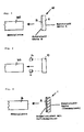
- a plastic edge 10 which consists of a co-extruded Thermoplastic exists. It has two layers of different hardness. The outside, i.e. layer 11 facing away from the plate body 30 made of a plastic of hardness A, while the one facing the plate body Layer 12 of the plastic edge 10 consists of a plastic of hardness B, wherein the hardness A is greater than the hardness B.
- the thickness of the plastic edge 10 can vary and be adapted to the requirements. According to an embodiment of the invention the edge has a thickness of about 2mm.
- the outer layer 11 great hardness can have a thickness of about 1.5mm, while that of the furniture body 30 lying layer 12 may have a thickness of about 0.5 mm.
- the furniture plate 30 can be made of different materials, e.g. B. made of plastic his.
- the furniture plate 30 shown in Fig. 1 consists of a wood material. she can consist of pressboard and / or have a layer structure.
- the plastic edge 10 is immediately and without glue on the body of the furniture panel 30 added.
- the internal, softer layer 12 reheated and melted so that it the adhesive function takes over when the plastic edge is opened.
- the connection itself then preferably takes place in continuous systems in which the plastic edge 10 with its melted layer 12 on the corresponding edge of the furniture panel body is added.
- the reheated layer 12 cools and solidifies again so that it sticks to the furniture panel body.
- the plastic edge is on welded on the furniture panel body.
- Fig. 2 shows the welding of the plastic edge 10 and the furniture panel 30 by means of Laser.
- the plastic edge 10 can basically be connected like that previously be described with Fig. 1 plastic edge.
- Fig. 1 plastic edge For an alternative Implementation of the invention, however, can be single-layer, i. H. without different Hardness areas should be formed.
- the side of the plastic edge 10 facing the furniture panel 30 is melted by means of laser light.
- the laser can be applied by two laser devices 13 and 14.
- different types of lasers can be used.
- diode lasers or semiconductor lasers with a wavelength of 0.8 to 1.0 ⁇ m are used to melt the surface of the plastic edge 10.
- the beam power can be selected differently, in particular depending on the material used, the desired melting speed and the desired melting volume.
- the laser devices 13 and 14 can each be operated with a beam power in the range of 10 2 watts.
- the processing parameters of the laser device are preferably selected such that the laser light is converted into heat near the surface of the plastic edge 10.
- the penetration depth of the laser radiation is less than 0.5 mm, in particular up to approximately 0.2 mm.
- the depth of the actual melting zone which becomes liquid can be less than 100 ⁇ m, preferably up to 50 ⁇ m.
- Plastic edges in all colors can advantageously on the furniture panel be welded because the weld seam or connection is always the same color like the plastic edge itself, because it is formed by it itself. It there are no color irregularities between the furniture panel and the edge, as is the case with the hot melt adhesive process.
Landscapes
- Engineering & Computer Science (AREA)
- Mechanical Engineering (AREA)
- Life Sciences & Earth Sciences (AREA)
- Physics & Mathematics (AREA)
- Wood Science & Technology (AREA)
- Toxicology (AREA)
- Health & Medical Sciences (AREA)
- Electromagnetism (AREA)
- Optics & Photonics (AREA)
- Manufacturing & Machinery (AREA)
- Chemical & Material Sciences (AREA)
- Composite Materials (AREA)
- Forests & Forestry (AREA)
- Lining Or Joining Of Plastics Or The Like (AREA)
- Laminated Bodies (AREA)
- Dry Formation Of Fiberboard And The Like (AREA)
- Securing Of Glass Panes Or The Like (AREA)
Abstract
Description
- Fig. 1
- eine schematische Darstellung des Fügevorganges einer Kunststoffkante auf eine Möbelplatte gemäß einer bevorzugten Ausführung der Erfindung,
- Fig. 2
- eine schematische Darstellung des Fügevorganges einer Kunststoffkante auf einer Möbelplatte gemäß einer alternativen bevorzugten Ausführung der Erfindung, nach der die Kunststoffkante mittels Laser aufgeschmolzen wird, und
- Fig. 3
- eine schematische Darstellung des Fügens einer Kunststoffkante auf eine Möbelplatte mittels Schmelzkleber.
Claims (17)
- Paneel, insbesondere Möbelplatte aus einem Holzwerkstoff, mit einer auf den Paneelkorpus (30) aufgebrachten Kunststoffkante (10), dadurch gekennzeichnet, daß eine Schweißverbindung zwischen der Kunststoffkante (10) und dem Paneelkorpus (30) vorgesehen ist.
- Paneel nach dem vorhergehenden Anspruch, wobei eine Laserschweißverbindung zwischen der Kunststoffkante (10) und dem Paneelkorpus (30) vorgesehen ist.
- Paneel nach einem der vorhergehenden Ansprüche, wobei die Kunststoffkante (10) aus Kunststoffen (11, 12) unterschiedlicher Härte besteht, insbesondere koextrudiert ist.
- Paneel nach einem der vorhergehenden Ansprüche, wobei ein Bereich größerer Härte der Kunststoffkante (10) eine größere Dicke als ein Bereich geringerer Härte besitzt, insbesondere mehr als doppelt, vorzugsweise etwa dreimal so dick ist wie der Bereich kleinerer Härte der Kunststoffkante (10).
- Paneel nach Anspruch 1 oder 2, wobei die Kunststoffkante aus einem einschichtigen Kunststoff frei von unterschiedlichen Härtebereichen besteht.
- Paneel nach einem der vorhergehenden Ansprüche, wobei eine auf den Paneelkorpus gefügte Oberfläche der Kunststoffkante vollständig mit dem Paneelkorpus verschweißt ist.
- Paneel nach einem der Ansprüche 1 bis 5, wobei eine auf den Paneelkorpus gefügte Oberfläche der Kunststoffkante nur partiell, vorzugsweise nur weniger als 50 % der auf den Paneelkorpus gefügten Oberfläche der Kunststoffkante mit dem Paneelkorpus verschweißt ist.
- Paneel nach einem der vorhergehenden Ansprüche, wobei die Kunststoffkante eine Schweiß- bzw. Aufschmelzschicht mit einer Tiefe von 0,2 mm oder weniger besitzt.
- Verfahren zur Herstellung eines Paneels, insbesondere einer Möbelplatte aus einem Holzwerkstoff, bei dem auf einem Paneelkorpus (30) eine Kunststoffkante (10) aufgebracht wird, dadurch gekennzeichnet, daß eine Oberfläche der Kunststoffkante (10) aufgeschmolzen und die Kunststoffkante mit ihrer aufgeschmolzenen Oberfläche auf den Paneelkorpus (30) gefügt wird.
- Verfahren nach dem vorhergehenden Anspruch, wobei eine Kunststoffkante (10) mit Bereichen (11, 12) unterschiedlicher Härte, insbesondere eine koextrudierte Thermoplast-Kante verwendet wird.
- Verfahren nach einem der vorhergehenden Ansprüche, wobei die Kunststoffkante durch Beaufschlagung mit einer Wärmequelle, insbesondere mit Heißluft, aufgeschmolzen wird.
- Verfahren nach einem der vorhergehenden Ansprüche 9 oder 10, wobei die Kunststoffkante (10) durch Laserbeaufschlagung aufgeschmolzen und mit dem Paneelkorpus verschweißt wird.
- Verfahren nach dem vorhergehenden Anspruch, wobei die Laserbeaufschlagung mit Laserlicht von einer Wellenlänge im Bereich von 0,7 bis 30 µm, vorzugsweise 0,8 bis 1,0 µm durchgeführt wird.
- Verfahren nach einem der vorhergehenden Ansprüche, wobei die Kunststoffkante (10) mittels einer Laservorrichtung (13, 14) mit einer Strahlleistung im Bereich von 102 Watt aufgeschmolzen wird.
- Verfahren nach einem der vorhergehenden Ansprüche, wobei eine Laserbeaufschlagung der Kunststoffkante (10) derart erfolgt, daß eine Eindringtiefe der Laserstrahlung weniger als 0,5 mm, vorzugsweise etwa 0,05 bis 0,2 mm beträgt.
- Verfahren nach einem der vorhergehenden Ansprüche, wobei die mit dem Paneelkorpus zu fügende Oberfläche der Kunststoffkante insbesondere mittels Laserbeaufschlagung nur partiell, vorzugsweise weniger als 50 % der zu fügenden Fläche aufgeschmolzen und mit dem Paneelkorpus verschweißt werden.
- Verfahren nach einem der vorhergehenden Ansprüche, wobei die Kunststoffkante (10) im Durchlauf an den Paneelkorpus (30) gefahren wird.
Priority Applications (1)
| Application Number | Priority Date | Filing Date | Title |
|---|---|---|---|
| DE50103712.8A DE50103712C9 (de) | 2000-06-13 | 2001-06-08 | Möbelplatte und Verfahren zu deren Herstellung |
Applications Claiming Priority (2)
| Application Number | Priority Date | Filing Date | Title |
|---|---|---|---|
| DE10029043A DE10029043A1 (de) | 2000-06-13 | 2000-06-13 | Möbelplatte und Verfahren zu deren Herstellung |
| DE10029043 | 2000-06-13 |
Publications (2)
| Publication Number | Publication Date |
|---|---|
| EP1163864A1 true EP1163864A1 (de) | 2001-12-19 |
| EP1163864B1 EP1163864B1 (de) | 2004-09-22 |
Family
ID=7645534
Family Applications (1)
| Application Number | Title | Priority Date | Filing Date |
|---|---|---|---|
| EP01114004A Expired - Lifetime EP1163864B1 (de) | 2000-06-13 | 2001-06-08 | Möbelplatte und Verfahren zu deren Herstellung |
Country Status (3)
| Country | Link |
|---|---|
| EP (1) | EP1163864B1 (de) |
| AT (1) | ATE276689T1 (de) |
| DE (2) | DE10029043A1 (de) |
Cited By (39)
| Publication number | Priority date | Publication date | Assignee | Title |
|---|---|---|---|---|
| DE102004017319B3 (de) * | 2004-04-06 | 2005-08-11 | Ludewig Möbelteile GmbH | Verfahren zum Herstellen einer verglasten Platte |
| DE202007011911U1 (de) | 2007-08-24 | 2009-01-08 | Rehau Ag + Co | Kantenleiste für Möbelstücke |
| WO2010149376A1 (de) | 2009-06-25 | 2010-12-29 | Ima Klessmann Gmbh | Bearbeitungszentrum |
| DE202009011403U1 (de) | 2009-08-21 | 2010-12-30 | Rehau Ag + Co. | Profilleiste |
| EP2311596A1 (de) | 2009-10-13 | 2011-04-20 | IMA Klessmann GmbH Holzbearbeitungssysteme | Vorrichtung und Verfahren zur Bekantung von Werkstücken |
| DE102009050859A1 (de) | 2009-10-27 | 2011-04-28 | Ima Klessmann Gmbh Holzbearbeitungssysteme | Vorrichtung und Verfahren zur Bekantung von Werkstücken |
| DE102009050858A1 (de) | 2009-10-27 | 2011-04-28 | Ima Klessmann Gmbh Holzbearbeitungssysteme | Vorrichtung und Verfahren zur Bekantung von Werkstücken |
| ITMO20090298A1 (it) * | 2009-12-18 | 2011-06-19 | Scm Group Spa | Apparato e metodo di incollaggio |
| EP2366540A1 (de) * | 2010-03-15 | 2011-09-21 | Mkt Moderne Kunststoff-Technik Gebrüder Eschbach Gmbh | Kantenleiste aus thermoplastischem Kunststoffmaterial, insbesondere für Möbelplatten |
| EP2511059A1 (de) | 2011-04-11 | 2012-10-17 | IMA Klessmann GmbH Holzbearbeitungssysteme | Vorrichtung und Verfahren zur Bekantung von Werkstücken |
| WO2013152866A1 (de) | 2012-04-12 | 2013-10-17 | Bulthaup Gmbh & Co. Kg | Kunststoffkante, möbelpaneel und verfahren zur herstellung eines möbelpaneels mit kunststoffkante |
| EP2653513A2 (de) | 2012-04-20 | 2013-10-23 | Jowat AG | Verklebungsverfahren und auf diese Weise hergestellte Produkte |
| EP2694272A1 (de) | 2011-04-01 | 2014-02-12 | Christof Schulte-Göbel | Schmalflächenbeschichtungsvorrichtung und verfahren zum aufbringen einer wärmeaktivierbaren kantenbeschichtung mittels heissluft oder heissgas |
| CN104015324A (zh) * | 2014-05-27 | 2014-09-03 | 东莞市华立实业股份有限公司 | 一种共挤成型封边条的制备工艺 |
| DE202015104158U1 (de) | 2015-08-07 | 2015-08-18 | Döllken-Kunststoffverarbeitung Gmbh | Kantenleiste |
| US20150239009A1 (en) * | 2012-08-03 | 2015-08-27 | Homag Holzbearbeitungssysteme Gmbh | Method and device for coating workpieces |
| EP2965905A1 (de) | 2014-07-11 | 2016-01-13 | Döllken Kunststoffverarbeitung GmbH | Kantenleiste |
| US20160235192A1 (en) * | 2007-08-24 | 2016-08-18 | Uwe Krämer | Edge trim for pieces of furniture |
| WO2016170117A1 (de) * | 2015-04-23 | 2016-10-27 | Döllken-Kunststoffverarbeitung Gmbh | Verfahren zur herstellung eines dekorativen profilkörpers, insbesondere einer kantenleiste |
| CN106272879A (zh) * | 2016-08-20 | 2017-01-04 | 合肥志邦家居有限公司 | 一种厨柜门板无缝封边工艺 |
| US9565943B2 (en) | 2007-08-24 | 2017-02-14 | Rehau Ag & Co | Edge trim for pieces of furniture |
| DE202015106625U1 (de) | 2015-12-04 | 2017-03-07 | Rehau Ag + Co | Kantenleisten für Möbelstücke |
| DE202016103409U1 (de) | 2016-06-28 | 2017-09-29 | Rehau Ag + Co | Kantenleiste für Möbelstücke |
| DE102017115360A1 (de) | 2017-07-10 | 2019-01-10 | Surteco Gmbh | Verfahren zum Befestigen einer Kantenleiste |
| DE102017122249A1 (de) | 2017-09-26 | 2019-03-28 | Homag Gmbh | Applikator zum thermischen Aktivieren einer Funktionsschicht eines Beschichtungsmaterials |
| DE102018201088A1 (de) | 2018-01-24 | 2019-07-25 | Homag Gmbh | Applikator zum Aktivieren einer Funktionsschicht eines Beschichtungsmaterials |
| EP3365171B1 (de) | 2015-10-22 | 2019-10-02 | Fritz Egger GmbH & Co. OG | Kantenprofil für einen plattenförmigen werkstoff und plattenförmiger werkstoff |
| US10442131B2 (en) | 2013-12-23 | 2019-10-15 | MKT Moderne Kunstoff-Technik Gebruder Eschbach GmbH | Edge strip |
| DE202018106965U1 (de) * | 2018-12-06 | 2020-03-09 | Rehau Ag + Co | Bauelement, insbesondere Türblatt |
| DE202018107256U1 (de) | 2018-12-19 | 2020-03-20 | Rehau Ag + Co | Bauelement, insbesondere Plattenelement |
| EP3090857B1 (de) | 2015-05-04 | 2020-07-22 | HOMAG GmbH | Beschichtungsmaterial zur beschichtung unsteter oberflächen sowie verfahren |
| US10954412B1 (en) | 2015-02-05 | 2021-03-23 | Ultra Tech Extrusions of Tennessee, inc. | Extended melt-temp range and low energy absorptive edge banding adhesive system and edge banding |
| EP3827703A1 (de) | 2019-11-27 | 2021-06-02 | REHAU AG + Co | Profilanordnung für bauelemente, möbelplatten und dergleichen |
| EP2347873B1 (de) * | 2005-11-23 | 2022-03-23 | HOMAG GmbH | Verfahren und Vorrichtung zur Beschichtung von Bauteilen |
| DE102021122622A1 (de) | 2021-07-02 | 2023-01-05 | Jowat Se | Kantenbeschichtung von insbesondere plattenförmigen Substraten |
| WO2023274613A1 (de) | 2021-07-02 | 2023-01-05 | Jowat Se | Kantenbeschichtung von insbesondere plattenförmigen substraten |
| WO2026047113A1 (de) | 2024-08-29 | 2026-03-05 | REHAU Industries SE & Co. KG | Verfahren zur schmalflächenbeschichtung eines plattenelementes sowie mit diesem verfahren hergestelltes plattenelement |
| WO2026047117A1 (de) | 2024-08-29 | 2026-03-05 | REHAU Industries SE & Co. KG | Verfahren zur schmalflächenbeschichtung eines plattenelementes |
| DE102024127022A1 (de) | 2024-09-19 | 2026-03-19 | REHAU Industries SE & Co. KG | Verfahren zur Schmalflächenbeschichtung eines Plattenelementes |
Families Citing this family (28)
| Publication number | Priority date | Publication date | Assignee | Title |
|---|---|---|---|---|
| DE202006021312U1 (de) | 2006-05-06 | 2015-09-18 | Döllken-Kunststoffverarbeitung Gmbh | Deckleiste |
| DE102006021171A1 (de) * | 2006-05-06 | 2007-11-08 | W. Döllken & Co. GmbH | Deckleiste |
| DE102007010825A1 (de) * | 2006-12-21 | 2008-06-26 | Wilhelm Karmann Gmbh | Verfahren zur Anbindung einer Kunststoffscheibe an einen Verdeckbezug und Verdeck eines Cabriolet-Fahrzeugs |
| DE102010004092B4 (de) | 2010-01-07 | 2014-01-09 | Ima Klessmann Gmbh Holzbearbeitungssysteme | Vorrichtung und Verfahren zur Bekantung von Werkstücken |
| DE202010004931U1 (de) | 2010-03-15 | 2010-07-29 | MKT Moderne Kunststoff-Technik Gebrüder Eschbach GmbH | Kantenleiste aus thermoplastischem Kunststoffmaterial, insbesondere für Möbelplatten |
| EP2374587B1 (de) | 2010-04-09 | 2015-07-29 | Homag Holzbearbeitungssysteme AG | Verfahren zum Herstellen von Beschichtungsmaterial |
| DE202011110713U1 (de) | 2011-04-01 | 2015-10-09 | Christof Schulte-Göbel | Schmalflächenbeschichtungsvorrichtung und Auslaß zum Aufbringen einer kleberfrei wärmeaktivierbaren Kantenbeschichtung mittels Heißluft oder Heißgas |
| DE102011104980A1 (de) | 2011-06-20 | 2012-12-20 | MKT Moderne Kunststoff-Technik Gebrüder Eschbach GmbH | Kantenleiste aus thermoplastischem Kunststoffmaterial, insbesondere für Möbelplatten |
| DE202012012859U1 (de) | 2012-03-31 | 2014-02-25 | Christof Schulte-Göbel | Schmalflächenbeschichtungsvorrichtung zum Aufbringen einer kleberfrei wärmeaktivierbaren Kantenbeschichtung mittels Heißluft oder Heißgas |
| DE102012112606B4 (de) | 2012-12-19 | 2020-07-09 | Surteco Gmbh | Verfahren zur Herstellung einer Kantenleiste, Kantenleiste und Verwendung einer Kantenleiste |
| DE102013102227A1 (de) | 2013-03-06 | 2014-09-11 | W. Döllken & Co. GmbH | Kantenleiste |
| DE102013102351A1 (de) | 2013-03-08 | 2014-09-11 | W. Döllken & Co. GmbH | Verfahren zum Vergüten von Möbelplatten |
| DE102013222636A1 (de) | 2013-11-07 | 2015-05-07 | Homag Holzbearbeitungssysteme Gmbh | Verfahren zum Aufbringen einer Beschichtung auf Werkstücke und Vorrichtung zum Beschichten von Werkstücken |
| EP2886301B1 (de) | 2013-12-19 | 2020-04-15 | REHAU AG + Co | Verfahren zur anbringung von kantenbändern an möbelplatten |
| DE102014101211A1 (de) | 2014-01-31 | 2015-08-06 | Rehau Ag + Co. | Verfahren zur Herstellung eines Kantenbandes |
| DE102014103725A1 (de) | 2014-03-19 | 2015-10-08 | Holz-Her Gmbh | Vorrichtung zum Fixieren eines Kantenmaterials |
| DE102014214035A1 (de) | 2014-07-18 | 2016-01-21 | Homag Holzbearbeitungssysteme Gmbh | Verfahren, Vorrichtung und Syntheseelement zum Verbinden eines Kantenmaterials mit einem Werkstück |
| DE102014115703A1 (de) | 2014-10-29 | 2016-05-04 | Döllken-Kunststoffverarbeitung Gmbh | Verfahren und Vorrichtung zum Befestigen einer Kantenleiste |
| DE202014106170U1 (de) | 2014-12-19 | 2016-03-23 | Rehau Ag + Co | Kantenleiste für Möbelstücke |
| DE202014106167U1 (de) | 2014-12-19 | 2016-03-24 | Rehau Ag + Co | Kantenleiste für Möbelstücke |
| DE202014106173U1 (de) | 2014-12-19 | 2016-03-23 | Rehau Ag + Co | Kantenleiste für Möbelstücke |
| DE202014106171U1 (de) | 2014-12-19 | 2016-03-24 | Rehau Ag + Co | Kantenleiste für Möbelstücke |
| DE102016118644A1 (de) | 2016-09-30 | 2018-04-05 | Döllken-Kunststoffverarbeitung Gmbh | Kantenleiste |
| DE202017102859U1 (de) | 2017-05-12 | 2018-08-23 | Döllken-Kunststoffverarbeitung Gmbh | Kantenleiste |
| DE102017210261A1 (de) | 2017-06-20 | 2018-12-20 | Homag Gmbh | Verfahren und Vorrichtung zum thermischen Aktivieren einer Funktionsschicht eines Beschichtungsmaterials |
| DE102017118660A1 (de) | 2017-08-16 | 2019-02-21 | Homag Gmbh | Applikator zum thermischen Aktivieren einer Funktionsschicht eines Beschichtungsmaterials |
| DE102018125609B4 (de) * | 2018-10-16 | 2021-11-25 | Surteco Gmbh | Verfahren und Vorrichtung zum Befestigen einer Kantenleiste |
| ES2953531T3 (es) | 2020-08-07 | 2023-11-14 | Fritz Egger Gmbh & Co Og | Tira de borde para piezas de trabajo, en particular piezas de mobiliario |
Citations (5)
| Publication number | Priority date | Publication date | Assignee | Title |
|---|---|---|---|---|
| DD257797A1 (de) * | 1987-02-27 | 1988-06-29 | Wtz Holzverarbeitende Ind | Verfahren zur herstellung von klebstofffreien verbindungen aus thermoplast- und holzwerkstoff |
| EP0500943A1 (de) * | 1990-07-26 | 1992-09-02 | Du Pont-Mitsui Polychemicals Co., Ltd. | Verfahren zur herstellung eines zylindrischen teils eines papierbehälters |
| WO1993006995A1 (en) * | 1991-10-10 | 1993-04-15 | Byggelit Lockne Ab | Method for fixing an edge list on a wood fibreboard and an edge list for making the method possible |
| EP0673761A1 (de) * | 1994-03-22 | 1995-09-27 | Degussa Aktiengesellschaft | Vollständig recyclierbarer Verbundkörper,insbesondere zur Herstellung von Möbelplatten |
| EP1080854A2 (de) * | 1999-08-25 | 2001-03-07 | W. Döllken & Co GmbH | Verfahren zum Befestigen von Deckleisten auf den Schmalseiten von Möbelplatten |
Family Cites Families (5)
| Publication number | Priority date | Publication date | Assignee | Title |
|---|---|---|---|---|
| DE7109575U (de) * | 1971-12-16 | Bosch R Gmbh | Abdeckplatte für Hausgeräte | |
| DE4104952A1 (de) * | 1991-02-18 | 1992-08-20 | Meier Metallwarenfab Gmbh Co | Verfahren zur herstellung von platten und hiernach hergestellte platte, insbesondere tisch-, abdeckplatte od. dgl. |
| DE19609906A1 (de) * | 1996-03-14 | 1997-09-18 | Rudolf Ostermann Gmbh | Stegkante mit angeklebtem Steg |
| DE19640961C1 (de) * | 1996-10-04 | 1998-01-22 | Eickel U Spindeldreher Gmbh | Verfahren zur Herstellung einer Arbeits- oder Abdeckplatte sowie Rahmenprofil zur Durchführung des Verfahrens |
| DE19830524A1 (de) * | 1998-07-08 | 2000-01-13 | Kunze Kati | Lagenplatte |
-
2000
- 2000-06-13 DE DE10029043A patent/DE10029043A1/de not_active Ceased
-
2001
- 2001-06-08 DE DE50103712.8A patent/DE50103712C9/de not_active Expired - Lifetime
- 2001-06-08 EP EP01114004A patent/EP1163864B1/de not_active Expired - Lifetime
- 2001-06-08 AT AT01114004T patent/ATE276689T1/de not_active IP Right Cessation
Patent Citations (5)
| Publication number | Priority date | Publication date | Assignee | Title |
|---|---|---|---|---|
| DD257797A1 (de) * | 1987-02-27 | 1988-06-29 | Wtz Holzverarbeitende Ind | Verfahren zur herstellung von klebstofffreien verbindungen aus thermoplast- und holzwerkstoff |
| EP0500943A1 (de) * | 1990-07-26 | 1992-09-02 | Du Pont-Mitsui Polychemicals Co., Ltd. | Verfahren zur herstellung eines zylindrischen teils eines papierbehälters |
| WO1993006995A1 (en) * | 1991-10-10 | 1993-04-15 | Byggelit Lockne Ab | Method for fixing an edge list on a wood fibreboard and an edge list for making the method possible |
| EP0673761A1 (de) * | 1994-03-22 | 1995-09-27 | Degussa Aktiengesellschaft | Vollständig recyclierbarer Verbundkörper,insbesondere zur Herstellung von Möbelplatten |
| EP1080854A2 (de) * | 1999-08-25 | 2001-03-07 | W. Döllken & Co GmbH | Verfahren zum Befestigen von Deckleisten auf den Schmalseiten von Möbelplatten |
Cited By (85)
| Publication number | Priority date | Publication date | Assignee | Title |
|---|---|---|---|---|
| DE102004017319B3 (de) * | 2004-04-06 | 2005-08-11 | Ludewig Möbelteile GmbH | Verfahren zum Herstellen einer verglasten Platte |
| DE102006056010C5 (de) * | 2005-11-23 | 2024-01-11 | Homag Holzbearbeitungssysteme Ag | Vorrichtung zur Beschichtung von Bauteilen |
| EP2347873B1 (de) * | 2005-11-23 | 2022-03-23 | HOMAG GmbH | Verfahren und Vorrichtung zur Beschichtung von Bauteilen |
| US9565943B2 (en) | 2007-08-24 | 2017-02-14 | Rehau Ag & Co | Edge trim for pieces of furniture |
| EP2368708A1 (de) | 2007-08-24 | 2011-09-28 | Rehau AG & Co | Kantenleiste für Möbelstücke |
| CN103584531A (zh) * | 2007-08-24 | 2014-02-19 | 雷奥两合股份公司 | 家具的边缘嵌条 |
| RU2524931C2 (ru) * | 2007-08-24 | 2014-08-10 | Рехау Аг + Ко | Окантовочная планка для предметов мебели |
| US20160235192A1 (en) * | 2007-08-24 | 2016-08-18 | Uwe Krämer | Edge trim for pieces of furniture |
| EP2180995B1 (de) | 2007-08-24 | 2019-12-25 | Rehau AG + Co | Kantenleiste für möbelstücke |
| US20190298056A1 (en) * | 2007-08-24 | 2019-10-03 | Rehau Ag + Co. | Edge trim for pieces of furniture |
| EP2368708B1 (de) | 2007-08-24 | 2025-03-05 | REHAU Industries SE & Co. KG | Kantenleiste für möbelstücke |
| US10327543B2 (en) * | 2007-08-24 | 2019-06-25 | Rehau Ag + Co. | Edge trim for pieces of furniture |
| US10905233B2 (en) * | 2007-08-24 | 2021-02-02 | Rehau Ag + Co. | Edge trim for pieces of furniture |
| WO2009026977A1 (de) | 2007-08-24 | 2009-03-05 | Rehau Ag + Co | Kantenleiste für möbelstücke |
| DE202008018014U1 (de) | 2007-08-24 | 2011-06-09 | REHAU AG + Co, 95111 | Kantenleiste für Möbelstücke |
| DE202008018036U1 (de) | 2007-08-24 | 2011-06-09 | REHAU AG + Co, 95111 | Kantenleiste für Möbelstücke |
| DE202008018034U1 (de) | 2007-08-24 | 2011-06-09 | REHAU AG + Co, 95111 | Kantenleiste für Möbelstücke |
| CN103584531B (zh) * | 2007-08-24 | 2017-04-12 | 雷奥两合股份公司 | 家具的边缘嵌条 |
| DE202007011911U1 (de) | 2007-08-24 | 2009-01-08 | Rehau Ag + Co | Kantenleiste für Möbelstücke |
| EP2363283A1 (de) | 2007-08-24 | 2011-09-07 | Rehau AG & Co | Kantenleiste für Möbelstücke |
| EP2366542A1 (de) | 2007-08-24 | 2011-09-21 | Rehau AG & Co | Kantenleiste für Möbelstücke |
| DE202008017798U1 (de) | 2007-08-24 | 2010-07-15 | Rehau Ag + Co | Kantenleiste für Möbelstücke |
| DE202008018641U1 (de) | 2007-08-24 | 2017-03-01 | Rehau Ag + Co. | Kantenleiste für Möbelstücke |
| DE202008018633U1 (de) | 2007-08-24 | 2017-01-18 | Rehau Ag + Co | Kantenleiste für Möbelstücke |
| RU2475359C2 (ru) * | 2007-08-24 | 2013-02-20 | Рехау Аг + Ко | Окантовочная планка для предметов мебели |
| WO2010149376A1 (de) | 2009-06-25 | 2010-12-29 | Ima Klessmann Gmbh | Bearbeitungszentrum |
| DE102009030641B3 (de) * | 2009-06-25 | 2011-02-10 | Ima Klessmann Gmbh Holzbearbeitungssysteme | Bearbeitungszentrum |
| WO2011020543A1 (de) | 2009-08-21 | 2011-02-24 | Rehau Ag + Co | Profilleiste |
| DE202009011403U1 (de) | 2009-08-21 | 2010-12-30 | Rehau Ag + Co. | Profilleiste |
| DE102009049107B4 (de) * | 2009-10-13 | 2014-01-09 | Ima Klessmann Gmbh Holzbearbeitungssysteme | Vorrichtung und Verfahren zur Bekantung von Werkstücken |
| DE102009049107A1 (de) | 2009-10-13 | 2011-04-21 | Ima Klessmann Gmbh Holzbearbeitungssysteme | Vorrichtung und Verfahren zur Bekantung von Werkstücken |
| EP2311596A1 (de) | 2009-10-13 | 2011-04-20 | IMA Klessmann GmbH Holzbearbeitungssysteme | Vorrichtung und Verfahren zur Bekantung von Werkstücken |
| DE102009050859A1 (de) | 2009-10-27 | 2011-04-28 | Ima Klessmann Gmbh Holzbearbeitungssysteme | Vorrichtung und Verfahren zur Bekantung von Werkstücken |
| WO2011054446A1 (de) | 2009-10-27 | 2011-05-12 | Ima Klessmann Gmbh | Vorrichtung und verfahren zur bekantung von werkstücken |
| DE102009050858A1 (de) | 2009-10-27 | 2011-04-28 | Ima Klessmann Gmbh Holzbearbeitungssysteme | Vorrichtung und Verfahren zur Bekantung von Werkstücken |
| WO2011054445A1 (de) | 2009-10-27 | 2011-05-12 | Ima Klessmann Gmbh | Vorrichtung und verfahren zur bekantung von werkstücken |
| ITMO20090298A1 (it) * | 2009-12-18 | 2011-06-19 | Scm Group Spa | Apparato e metodo di incollaggio |
| EP2335891A1 (de) * | 2009-12-18 | 2011-06-22 | SCM Group S.p.A. | Klebevorrichtung und Verfahren zur Verklebung |
| EP2366540A1 (de) * | 2010-03-15 | 2011-09-21 | Mkt Moderne Kunststoff-Technik Gebrüder Eschbach Gmbh | Kantenleiste aus thermoplastischem Kunststoffmaterial, insbesondere für Möbelplatten |
| EP2694272A1 (de) | 2011-04-01 | 2014-02-12 | Christof Schulte-Göbel | Schmalflächenbeschichtungsvorrichtung und verfahren zum aufbringen einer wärmeaktivierbaren kantenbeschichtung mittels heissluft oder heissgas |
| EP2511059A1 (de) | 2011-04-11 | 2012-10-17 | IMA Klessmann GmbH Holzbearbeitungssysteme | Vorrichtung und Verfahren zur Bekantung von Werkstücken |
| WO2013152866A1 (de) | 2012-04-12 | 2013-10-17 | Bulthaup Gmbh & Co. Kg | Kunststoffkante, möbelpaneel und verfahren zur herstellung eines möbelpaneels mit kunststoffkante |
| DE102012007281A1 (de) | 2012-04-12 | 2013-10-17 | Bulthaup Gmbh & Co. Kg | Kunststoffkante, Möbelpaneel und Verfahren zur Herstellung eines Möbelpaneels mit Kunststoffkante |
| DE212013000011U1 (de) | 2012-04-12 | 2014-04-09 | Bulthaup Gmbh & Co. Kg | Kunststoffkante, Möbelpaneel und Vorrichtung zur Herstellung eines Möbelpaneels mit Kunststoffkante |
| DE102012008401A1 (de) | 2012-04-20 | 2013-10-24 | Jowat Ag | Verklebungsverfahren und auf diese Weise hergestellte Produkte |
| EP2653513A2 (de) | 2012-04-20 | 2013-10-23 | Jowat AG | Verklebungsverfahren und auf diese Weise hergestellte Produkte |
| US20150239009A1 (en) * | 2012-08-03 | 2015-08-27 | Homag Holzbearbeitungssysteme Gmbh | Method and device for coating workpieces |
| US10807121B2 (en) * | 2012-08-03 | 2020-10-20 | Homag Gmbh | Method and device for coating workpieces |
| US10442131B2 (en) | 2013-12-23 | 2019-10-15 | MKT Moderne Kunstoff-Technik Gebruder Eschbach GmbH | Edge strip |
| CN104015324A (zh) * | 2014-05-27 | 2014-09-03 | 东莞市华立实业股份有限公司 | 一种共挤成型封边条的制备工艺 |
| EP2965905A1 (de) | 2014-07-11 | 2016-01-13 | Döllken Kunststoffverarbeitung GmbH | Kantenleiste |
| DE102014109750A1 (de) | 2014-07-11 | 2016-01-14 | Döllken-Kunststoffverarbeitung Gmbh | Kantenleiste |
| US10954412B1 (en) | 2015-02-05 | 2021-03-23 | Ultra Tech Extrusions of Tennessee, inc. | Extended melt-temp range and low energy absorptive edge banding adhesive system and edge banding |
| US11746261B2 (en) | 2015-02-05 | 2023-09-05 | Ultra Tech Extrusions of Tennessee, inc. | Method of adhering extended melt-temp range and low energy absorptive edge banding adhesive system edge banding |
| US12319853B2 (en) | 2015-02-05 | 2025-06-03 | Ultra Tech Extrusions of Tennessee, inc. | Multi-phasic polymer blend for adhering an outer edge banding layer to a substrate |
| EP3722072A1 (de) * | 2015-04-23 | 2020-10-14 | SURTECO GmbH | Verfahren zur herstellung eines dekorativen profilkörpers, insbesondere einer kantenleiste |
| EP3285986B1 (de) | 2015-04-23 | 2020-07-22 | SURTECO GmbH | Verfahren zur herstellung eines dekorativen profilkörpers, insbesondere einer kantenleiste |
| WO2016170117A1 (de) * | 2015-04-23 | 2016-10-27 | Döllken-Kunststoffverarbeitung Gmbh | Verfahren zur herstellung eines dekorativen profilkörpers, insbesondere einer kantenleiste |
| EP3090857B1 (de) | 2015-05-04 | 2020-07-22 | HOMAG GmbH | Beschichtungsmaterial zur beschichtung unsteter oberflächen sowie verfahren |
| DE202015104158U1 (de) | 2015-08-07 | 2015-08-18 | Döllken-Kunststoffverarbeitung Gmbh | Kantenleiste |
| US11021006B2 (en) | 2015-10-22 | 2021-06-01 | Fritz Egger Gmbh & Co. Og | Edge profile for a sheet-like material, and sheet-like material |
| EP3365171B2 (de) † | 2015-10-22 | 2025-04-09 | Fritz Egger GmbH & Co. OG | Kantenprofil für einen plattenförmigen werkstoff und plattenförmiger werkstoff |
| EP3365171B1 (de) | 2015-10-22 | 2019-10-02 | Fritz Egger GmbH & Co. OG | Kantenprofil für einen plattenförmigen werkstoff und plattenförmiger werkstoff |
| DE202015106625U1 (de) | 2015-12-04 | 2017-03-07 | Rehau Ag + Co | Kantenleisten für Möbelstücke |
| DE202016103409U1 (de) | 2016-06-28 | 2017-09-29 | Rehau Ag + Co | Kantenleiste für Möbelstücke |
| WO2018001545A1 (de) | 2016-06-28 | 2018-01-04 | Rehau Ag + Co | Kantenleiste für möbelstücke |
| EP3475089B1 (de) | 2016-06-28 | 2020-08-05 | REHAU AG + Co | Kantenleiste für möbelstücke |
| CN106272879A (zh) * | 2016-08-20 | 2017-01-04 | 合肥志邦家居有限公司 | 一种厨柜门板无缝封边工艺 |
| WO2019011544A1 (de) | 2017-07-10 | 2019-01-17 | Döllken-Kunststoffverarbeitung Gmbh | Kantenleiste und verfahren zum befestigen einer kantenleiste |
| DE102017115360A1 (de) | 2017-07-10 | 2019-01-10 | Surteco Gmbh | Verfahren zum Befestigen einer Kantenleiste |
| DE102017122249A1 (de) | 2017-09-26 | 2019-03-28 | Homag Gmbh | Applikator zum thermischen Aktivieren einer Funktionsschicht eines Beschichtungsmaterials |
| DE102018201088A1 (de) | 2018-01-24 | 2019-07-25 | Homag Gmbh | Applikator zum Aktivieren einer Funktionsschicht eines Beschichtungsmaterials |
| EP3663499A1 (de) | 2018-12-06 | 2020-06-10 | REHAU AG + Co | Bauelement, insbesondere türblatt |
| DE202018106965U1 (de) * | 2018-12-06 | 2020-03-09 | Rehau Ag + Co | Bauelement, insbesondere Türblatt |
| DE202018107256U1 (de) | 2018-12-19 | 2020-03-20 | Rehau Ag + Co | Bauelement, insbesondere Plattenelement |
| EP3670182A1 (de) | 2018-12-19 | 2020-06-24 | REHAU AG + Co | Bauelement, insbesondere plattenelement |
| EP3827703A1 (de) | 2019-11-27 | 2021-06-02 | REHAU AG + Co | Profilanordnung für bauelemente, möbelplatten und dergleichen |
| WO2023274613A1 (de) | 2021-07-02 | 2023-01-05 | Jowat Se | Kantenbeschichtung von insbesondere plattenförmigen substraten |
| EP4341058B1 (de) | 2021-07-02 | 2025-04-23 | Jowat SE | Kantenbeschichtung von insbesondere plattenförmigen substraten |
| DE102021122622A1 (de) | 2021-07-02 | 2023-01-05 | Jowat Se | Kantenbeschichtung von insbesondere plattenförmigen Substraten |
| WO2026047113A1 (de) | 2024-08-29 | 2026-03-05 | REHAU Industries SE & Co. KG | Verfahren zur schmalflächenbeschichtung eines plattenelementes sowie mit diesem verfahren hergestelltes plattenelement |
| DE102024124682A1 (de) | 2024-08-29 | 2026-03-05 | REHAU Industries SE & Co. KG | Verfahren zur Schmalflächenbeschichtung eines Plattenelementes |
| WO2026047117A1 (de) | 2024-08-29 | 2026-03-05 | REHAU Industries SE & Co. KG | Verfahren zur schmalflächenbeschichtung eines plattenelementes |
| DE102024127022A1 (de) | 2024-09-19 | 2026-03-19 | REHAU Industries SE & Co. KG | Verfahren zur Schmalflächenbeschichtung eines Plattenelementes |
| WO2026061741A1 (de) | 2024-09-19 | 2026-03-26 | REHAU Industries SE & Co. KG | Verfahren zur schmalflächenbeschichtung eines plattenelementes |
Also Published As
| Publication number | Publication date |
|---|---|
| DE10029043A1 (de) | 2002-01-03 |
| DE50103712C9 (de) | 2016-07-21 |
| EP1163864B1 (de) | 2004-09-22 |
| ATE276689T1 (de) | 2004-10-15 |
| DE50103712C5 (de) | 2016-04-07 |
| DE50103712D1 (de) | 2004-10-28 |
Similar Documents
| Publication | Publication Date | Title |
|---|---|---|
| EP1163864B1 (de) | Möbelplatte und Verfahren zu deren Herstellung | |
| DE2747978C3 (de) | Verfahren zum Herstellen einer endlosen Verbundbahn | |
| EP2366542A1 (de) | Kantenleiste für Möbelstücke | |
| DE202007019633U1 (de) | Deckleiste | |
| DE202013011790U1 (de) | Kantenleiste | |
| DE4422449C2 (de) | Verfahren zur Herstellung eines schichtförmigen Verbundwerkstoffes | |
| EP2746045A1 (de) | Sperrholzplatte | |
| EP0545390B1 (de) | Platte mit Postformingkante | |
| DE202020107571U1 (de) | Möbelfrontplatte | |
| DE3810053A1 (de) | Arbeitsplatte und verfahren zu ihrer herstellung | |
| DE102011050874A1 (de) | Schichtplatte | |
| DE102015121551A1 (de) | Kantenleiste für Möbelstücke | |
| DE102005003123A1 (de) | Verfahren zur Herstellung eines Paneels, insbesondere Fussbodenpaneels und Paneel, insbesondere Fussbodenpaneel | |
| DE10354460B3 (de) | Faltbare Platten | |
| EP2886301B1 (de) | Verfahren zur anbringung von kantenbändern an möbelplatten | |
| DE69312772T2 (de) | Platte für Arbeitstisch mit einer Wasserdichten Verbindung der Beschichtungsmaterialien | |
| WO2014095844A1 (de) | Kantenumleimer | |
| DE8701678U1 (de) | Naturholz-Umleimer | |
| EP2467254B1 (de) | Leichtbauplatte | |
| DE3241685C2 (de) | ||
| EP1925426A1 (de) | Verfahren und Vorrichtung zum Beschichten einer Holzwerkstoffplatte mit einer Folie | |
| DE10354461B3 (de) | Faltbare Platten | |
| DE4306063A1 (de) | Verfahren zur Herstellung von Furnierplatten | |
| DE202010004931U1 (de) | Kantenleiste aus thermoplastischem Kunststoffmaterial, insbesondere für Möbelplatten | |
| DE29714623U1 (de) | Kantenband |
Legal Events
| Date | Code | Title | Description |
|---|---|---|---|
| PUAI | Public reference made under article 153(3) epc to a published international application that has entered the european phase |
Free format text: ORIGINAL CODE: 0009012 |
|
| AK | Designated contracting states |
Kind code of ref document: A1 Designated state(s): AT CH DE ES FR IT LI Kind code of ref document: A1 Designated state(s): AT BE CH CY DE DK ES FI FR GB GR IE IT LI LU MC NL PT SE TR |
|
| AX | Request for extension of the european patent |
Free format text: AL;LT;LV;MK;RO;SI |
|
| 17P | Request for examination filed |
Effective date: 20020103 |
|
| AKX | Designation fees paid |
Free format text: AT CH DE ES FR IT LI |
|
| 17Q | First examination report despatched |
Effective date: 20021217 |
|
| GRAP | Despatch of communication of intention to grant a patent |
Free format text: ORIGINAL CODE: EPIDOSNIGR1 |
|
| GRAS | Grant fee paid |
Free format text: ORIGINAL CODE: EPIDOSNIGR3 |
|
| RAP1 | Party data changed (applicant data changed or rights of an application transferred) |
Owner name: BULTHAUP GMBH & CO KG |
|
| GRAA | (expected) grant |
Free format text: ORIGINAL CODE: 0009210 |
|
| AK | Designated contracting states |
Kind code of ref document: B1 Designated state(s): AT CH DE ES FR IT LI |
|
| PG25 | Lapsed in a contracting state [announced via postgrant information from national office to epo] |
Ref country code: IT Free format text: LAPSE BECAUSE OF FAILURE TO SUBMIT A TRANSLATION OF THE DESCRIPTION OR TO PAY THE FEE WITHIN THE PRESCRIBED TIME-LIMIT;WARNING: LAPSES OF ITALIAN PATENTS WITH EFFECTIVE DATE BEFORE 2007 MAY HAVE OCCURRED AT ANY TIME BEFORE 2007. THE CORRECT EFFECTIVE DATE MAY BE DIFFERENT FROM THE ONE RECORDED. Effective date: 20040922 Ref country code: FR Free format text: LAPSE BECAUSE OF FAILURE TO SUBMIT A TRANSLATION OF THE DESCRIPTION OR TO PAY THE FEE WITHIN THE PRESCRIBED TIME-LIMIT Effective date: 20040922 |
|
| REG | Reference to a national code |
Ref country code: CH Ref legal event code: EP |
|
| REG | Reference to a national code |
Ref country code: IE Ref legal event code: FG4D Free format text: GERMAN |
|
| REF | Corresponds to: |
Ref document number: 50103712 Country of ref document: DE Date of ref document: 20041028 Kind code of ref document: P |
|
| PG25 | Lapsed in a contracting state [announced via postgrant information from national office to epo] |
Ref country code: ES Free format text: LAPSE BECAUSE OF FAILURE TO SUBMIT A TRANSLATION OF THE DESCRIPTION OR TO PAY THE FEE WITHIN THE PRESCRIBED TIME-LIMIT Effective date: 20050102 |
|
| REG | Reference to a national code |
Ref country code: IE Ref legal event code: FD4D |
|
| PG25 | Lapsed in a contracting state [announced via postgrant information from national office to epo] |
Ref country code: AT Free format text: LAPSE BECAUSE OF NON-PAYMENT OF DUE FEES Effective date: 20050608 |
|
| PG25 | Lapsed in a contracting state [announced via postgrant information from national office to epo] |
Ref country code: CH Free format text: LAPSE BECAUSE OF NON-PAYMENT OF DUE FEES Effective date: 20050630 Ref country code: LI Free format text: LAPSE BECAUSE OF NON-PAYMENT OF DUE FEES Effective date: 20050630 |
|
| PLBE | No opposition filed within time limit |
Free format text: ORIGINAL CODE: 0009261 |
|
| STAA | Information on the status of an ep patent application or granted ep patent |
Free format text: STATUS: NO OPPOSITION FILED WITHIN TIME LIMIT |
|
| 26N | No opposition filed |
Effective date: 20050623 |
|
| EN | Fr: translation not filed | ||
| REG | Reference to a national code |
Ref country code: CH Ref legal event code: PL |
|
| REG | Reference to a national code |
Ref country code: DE Ref legal event code: R043 Ref document number: 50103712 Country of ref document: DE |
|
| REG | Reference to a national code |
Ref country code: DE Ref legal event code: R206 Ref document number: 50103712 Country of ref document: DE |
|
| REG | Reference to a national code |
Ref country code: DE Ref legal event code: R082 Ref document number: 50103712 Country of ref document: DE Representative=s name: KLUNKER IP PATENTANWAELTE PARTG MBB, DE |
|
| PGFP | Annual fee paid to national office [announced via postgrant information from national office to epo] |
Ref country code: DE Payment date: 20200729 Year of fee payment: 20 |
|
| REG | Reference to a national code |
Ref country code: DE Ref legal event code: R071 Ref document number: 50103712 Country of ref document: DE |