EP1162865A2 - Entladungslampe hoher Intensität, und Gerät zum Betreiben solch einer Lampe - Google Patents
Entladungslampe hoher Intensität, und Gerät zum Betreiben solch einer Lampe Download PDFInfo
- Publication number
- EP1162865A2 EP1162865A2 EP01113826A EP01113826A EP1162865A2 EP 1162865 A2 EP1162865 A2 EP 1162865A2 EP 01113826 A EP01113826 A EP 01113826A EP 01113826 A EP01113826 A EP 01113826A EP 1162865 A2 EP1162865 A2 EP 1162865A2
- Authority
- EP
- European Patent Office
- Prior art keywords
- voltage
- pair
- electrodes
- trigger wire
- discharge lamp
- Prior art date
- Legal status (The legal status is an assumption and is not a legal conclusion. Google has not performed a legal analysis and makes no representation as to the accuracy of the status listed.)
- Withdrawn
Links
Images


Classifications
-
- H—ELECTRICITY
- H01—ELECTRIC ELEMENTS
- H01J—ELECTRIC DISCHARGE TUBES OR DISCHARGE LAMPS
- H01J61/00—Gas-discharge or vapour-discharge lamps
- H01J61/02—Details
- H01J61/54—Igniting arrangements, e.g. promoting ionisation for starting
- H01J61/541—Igniting arrangements, e.g. promoting ionisation for starting using a bimetal switch
- H01J61/542—Igniting arrangements, e.g. promoting ionisation for starting using a bimetal switch and an auxiliary electrode inside the vessel
-
- H—ELECTRICITY
- H01—ELECTRIC ELEMENTS
- H01J—ELECTRIC DISCHARGE TUBES OR DISCHARGE LAMPS
- H01J61/00—Gas-discharge or vapour-discharge lamps
- H01J61/02—Details
- H01J61/54—Igniting arrangements, e.g. promoting ionisation for starting
- H01J61/547—Igniting arrangements, e.g. promoting ionisation for starting using an auxiliary electrode outside the vessel
-
- H—ELECTRICITY
- H05—ELECTRIC TECHNIQUES NOT OTHERWISE PROVIDED FOR
- H05B—ELECTRIC HEATING; ELECTRIC LIGHT SOURCES NOT OTHERWISE PROVIDED FOR; CIRCUIT ARRANGEMENTS FOR ELECTRIC LIGHT SOURCES, IN GENERAL
- H05B41/00—Circuit arrangements or apparatus for igniting or operating discharge lamps
- H05B41/02—Details
- H05B41/04—Starting switches
- H05B41/042—Starting switches using semiconductor devices
-
- H—ELECTRICITY
- H05—ELECTRIC TECHNIQUES NOT OTHERWISE PROVIDED FOR
- H05B—ELECTRIC HEATING; ELECTRIC LIGHT SOURCES NOT OTHERWISE PROVIDED FOR; CIRCUIT ARRANGEMENTS FOR ELECTRIC LIGHT SOURCES, IN GENERAL
- H05B41/00—Circuit arrangements or apparatus for igniting or operating discharge lamps
- H05B41/14—Circuit arrangements
- H05B41/16—Circuit arrangements in which the lamp is fed by dc or by low-frequency ac, e.g. by 50 cycles/sec ac, or with network frequencies
- H05B41/18—Circuit arrangements in which the lamp is fed by dc or by low-frequency ac, e.g. by 50 cycles/sec ac, or with network frequencies having a starting switch
- H05B41/19—Circuit arrangements in which the lamp is fed by dc or by low-frequency ac, e.g. by 50 cycles/sec ac, or with network frequencies having a starting switch for lamps having an auxiliary starting electrode
-
- H—ELECTRICITY
- H05—ELECTRIC TECHNIQUES NOT OTHERWISE PROVIDED FOR
- H05B—ELECTRIC HEATING; ELECTRIC LIGHT SOURCES NOT OTHERWISE PROVIDED FOR; CIRCUIT ARRANGEMENTS FOR ELECTRIC LIGHT SOURCES, IN GENERAL
- H05B41/00—Circuit arrangements or apparatus for igniting or operating discharge lamps
- H05B41/14—Circuit arrangements
- H05B41/26—Circuit arrangements in which the lamp is fed by power derived from dc by means of a converter, e.g. by high-voltage dc
- H05B41/28—Circuit arrangements in which the lamp is fed by power derived from dc by means of a converter, e.g. by high-voltage dc using static converters
- H05B41/288—Circuit arrangements in which the lamp is fed by power derived from dc by means of a converter, e.g. by high-voltage dc using static converters with semiconductor devices and specially adapted for lamps without preheating electrodes, e.g. for high-intensity discharge lamps, high-pressure mercury or sodium lamps or low-pressure sodium lamps
- H05B41/2881—Load circuits; Control thereof
-
- H—ELECTRICITY
- H05—ELECTRIC TECHNIQUES NOT OTHERWISE PROVIDED FOR
- H05B—ELECTRIC HEATING; ELECTRIC LIGHT SOURCES NOT OTHERWISE PROVIDED FOR; CIRCUIT ARRANGEMENTS FOR ELECTRIC LIGHT SOURCES, IN GENERAL
- H05B41/00—Circuit arrangements or apparatus for igniting or operating discharge lamps
- H05B41/14—Circuit arrangements
- H05B41/26—Circuit arrangements in which the lamp is fed by power derived from dc by means of a converter, e.g. by high-voltage dc
- H05B41/28—Circuit arrangements in which the lamp is fed by power derived from dc by means of a converter, e.g. by high-voltage dc using static converters
- H05B41/288—Circuit arrangements in which the lamp is fed by power derived from dc by means of a converter, e.g. by high-voltage dc using static converters with semiconductor devices and specially adapted for lamps without preheating electrodes, e.g. for high-intensity discharge lamps, high-pressure mercury or sodium lamps or low-pressure sodium lamps
- H05B41/292—Arrangements for protecting lamps or circuits against abnormal operating conditions
- H05B41/2928—Arrangements for protecting lamps or circuits against abnormal operating conditions for protecting the lamp against abnormal operating conditions
-
- H—ELECTRICITY
- H05—ELECTRIC TECHNIQUES NOT OTHERWISE PROVIDED FOR
- H05B—ELECTRIC HEATING; ELECTRIC LIGHT SOURCES NOT OTHERWISE PROVIDED FOR; CIRCUIT ARRANGEMENTS FOR ELECTRIC LIGHT SOURCES, IN GENERAL
- H05B41/00—Circuit arrangements or apparatus for igniting or operating discharge lamps
- H05B41/14—Circuit arrangements
- H05B41/36—Controlling
- H05B41/38—Controlling the intensity of light
- H05B41/382—Controlling the intensity of light during the transitional start-up phase
- H05B41/384—Controlling the intensity of light during the transitional start-up phase in case of hot-restriking
-
- Y—GENERAL TAGGING OF NEW TECHNOLOGICAL DEVELOPMENTS; GENERAL TAGGING OF CROSS-SECTIONAL TECHNOLOGIES SPANNING OVER SEVERAL SECTIONS OF THE IPC; TECHNICAL SUBJECTS COVERED BY FORMER USPC CROSS-REFERENCE ART COLLECTIONS [XRACs] AND DIGESTS
- Y02—TECHNOLOGIES OR APPLICATIONS FOR MITIGATION OR ADAPTATION AGAINST CLIMATE CHANGE
- Y02B—CLIMATE CHANGE MITIGATION TECHNOLOGIES RELATED TO BUILDINGS, e.g. HOUSING, HOUSE APPLIANCES OR RELATED END-USER APPLICATIONS
- Y02B20/00—Energy efficient lighting technologies, e.g. halogen lamps or gas discharge lamps
Definitions
- the present invention relates to high-intensity discharge lamps and high-intensity discharge lamp operating apparatuses.
- the present invention relates to high-intensity discharge lamps such as metal halide lamps, high pressure mercury lamps, and high pressure sodium lamps that are provided with a trigger wire.
- high-intensity discharge lamps such as metal halide lamps have been used for general illumination or spot illumination. In recent years, they are also widely used as a light source of OHPs and liquid crystal projectors.
- a metal halide lamp includes, for example, an arc tube (luminous bulb) made of quartz glass and a pair of electrodes spaced apart with a predetermined distance in the arc tube, and mercury and a metal halide are enclosed as luminous materials in the arc tube.
- the arc tube is sealed with electrode sealing portions at both ends, and the pair of electrodes are connected to respective external lead wires via metal foils hermetically sealed in the electrode sealing portions.
- the external lead wires are electrically connected to an operating circuit (driving device) of the lamp.
- the operating circuit includes a ballast for restricting current flow to less than a predetermined amount during operation and means for applying a high-voltage pulse voltage.
- the lighting operation of metal halide lamps is as follows. In order to start lighting operation, first, it is necessary to apply a voltage to the pair of electrodes to cause insulation breakdown to start discharge. A voltage necessary to cause the insulation breakdown is called “breakdown voltage", and the breakdown voltage is generally a high voltage of several hundreds times higher than the lamp voltage during steady-state operation.
- the breakdown voltage is as low as possible.
- a technique for lowering the breakdown voltage a configuration where a trigger wire (close conductor) is wound around the outer circumference of the arc tube is known, which is disclosed in Japanese Laid-Open Patent Publication No.8-69777, for example.
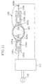
- FIG. 11 shows a metal halide lamp having this configuration.
- the metal halide lamp shown in FIG. 11 has an arc tube 101 and electrode sealing portions 102a and 102b, and a trigger wire 108 having a first end 108a and a second end 108b is spirally wound around the circumference of the arc tube 101.
- a pair of electrodes 103a and 103b are opposed to each other inside the arc tube 101.
- the pair of electrodes 103a and 103b are connected to external lead wires 105a and 105b via the metal foils 104a and 104b in electrode sealing portions 102a and 102b.
- the second end 108b of the trigger wire 108 is connected to the external lead 105b, and the first end 108a of the trigger wire 108 is wound around the end (near the base) of the electrode sealing portion 102a on the side of the arc tube 101.
- the external lead wires 105a and 105b are electrically connected to an operating circuit (driving device) 111, and the operating circuit 111 is electrically connected to a power supply 107.
- This metal halide lamp is provided with the trigger wire 108, so that the breakdown voltage can be reduced. This is caused by the following mechanism.
- the trigger wire 108 When a high-voltage pulse voltage is applied from the operation circuit 111 connected to the power supply 107 to the electrodes 103a and 103b, the trigger wire 108 has the same electric potential as that of the electrode 103b.
- the trigger wire 108 causes an electrical field having a large electric potential gradient to be formed inside the arc tube 101. This electrical field is likely to cause insulation breakdown of Xe gas between the electrodes 103a and 103b and thus the breakdown voltage can be reduced.
- the breakdown voltage can be reduced, color change, an increase of the lamp voltage, or devitrification, which is a phenomenon that the transparency is lost by opaqueness of the arc tube, may occur during operation of the lamp.
- the luminous flux maintenance factor is reduced, or the lamp cannot be turned on, and thus the lifetime of the lamp tends to be reduced.
- the inventors of the present invention found that the electrical field generated by the trigger wire 108 is a large factor.
- the voltage between the trigger wire 108 connected to the external lead wire 105b and the electrode 103a is also 65V.
- the distance between the electrodes 103a and 103b is 3.7mm
- the shortest distance between the first end 108a of the trigger wire 108 and the electrode 103a is 1mm
- the electric potential gradient of the electrical field formed between the electrodes 103a and 103b is 17.6V/mm.
- the electric potential gradient of the electrical field formed between the electrode 103a and the trigger wire 108 is 65V/mm, which is more than three times higher than 17.6V/mm, in the largest portion.
- the insulation breakdown of Xe gas is caused, and thus discharge is started, the temperature of the inner wall of the arc tube 101 is increased by subsequent discharge.
- enclosed material such as metal halide enclosed in the arc tube 101 is evaporated and further ionized.
- the ionized luminous material is affected more by the electrical field between the trigger wire 108 and the electrode 103a than by the electrical field between the electrodes 103a and 103b, and thus attracted more to the trigger wire 108.
- the applied driving voltage is alternating voltage
- the luminous material such as sodium in the form of positive ions are attracted to the trigger wire 108 , and sodium having a small ion radius moves in the quartz glass and leaks out of the arc tube 101 .
- the amount of the luminous material in the arc tube 101 is reduced, so that the optical characteristics (color temperature, lamp voltage, luminous flux maintenance factor etc.) are significantly changed, which was found by the inventor of the present invention.
- sodium or the like breaks the amorphous structure of the quartz glass while moving in the quartz glass, and crystallization of the quartz glass (phase transition to cristobalite) occurs, which causes opaqueness or devitrification of the quartz glass.
- a high-intensity discharge lamp of the present invention includes an arc tube including a pair of electrodes opposed to each other therein; and a trigger wire made of a conductive material provided in an outer circumference of the arc tube.
- the trigger wire is turned to be in a conductive state with one electrode of the pair of electrodes when a start-up voltage is applied across the pair of electrodes, and discharge is started between the pair of electrodes in a state where an electrical field is formed between the trigger wire that is in the conductive state and the other electrode of the pair of electrodes.
- a part of the trigger wire is arranged close to an external lead wire in an insulating state, the external lead wire being electrically connected to the one electrode, and when the start-up voltage is applied, insulation breakdown is caused between the part of the trigger wire and the external lead wire to establish the conductive state.
- the part of the trigger wire is arranged close to the external lead wire with a distance of less than 3mm.
- the part of the trigger wire is insulated from the external lead wire with air.
- an insulating tape is provided between the part of the trigger wire and the external lead wire for insulation.
- the high-intensity discharge lamp further includes a pair of sealing portions for sealing ends of the pair of electrodes, the sealing portions extending from the arc tube, wherein the trigger wire is wound around a region between the arc tube and one of the pair of sealing portions that seals an end of the other electrode.
- the arc tube is made of quartz glass.
- a metal halide is enclosed as a luminous material in the arc tube, and the metal halide includes an alkaline metal halide.
- the alkaline metal halide is a sodium halide.
- a high-intensity discharge lamp operating apparatus includes a high-intensity discharge lamp including an arc tube including a pair of electrodes opposed to each other therein, and a trigger wire made of a conductive material provided in an outer circumference of the arc tube; an operating circuit for operating the high-intensity discharge lamp.
- the trigger wire is not electrically connected to either one of the pair of electrodes.
- the operating circuit includes driving voltage applying means for applying a driving voltage for maintaining discharge after the discharge is started between the pair of electrodes, and start-up voltage applying means for applying a start-up voltage for starting discharge between the pair of electrodes.
- the trigger wire is electrically connected to the start-up voltage applying means, and each of the pair of electrodes is electrically connected to the driving voltage applying means.
- the start-up voltage applying means includes a timer for controlling the start-up voltage applying means so as to apply the start-up voltage to the trigger wire for a predetermined time during start-up.
- the start-up voltage applying means includes detecting means for detecting that lamp operation is started by discharge between the pair of electrodes; and controlling means for stopping application of the start-up voltage when the detecting means detects that lamp operation is started.
- the detecting means is a voltage detector that detects a change in voltage between the pair of electrodes.
- the detecting means is a current detector that detects a change in current flowing between the pair of electrodes.
- the high-intensity discharge lamp further includes a pair of sealing portions for sealing ends of the pair of electrodes, the sealing portion extending from the arc tube, and the trigger wire is wound around a region between one of the pair of sealing portions and the arc tube.
- the arc tube is made of quartz glass.
- the high-intensity discharge lamp is a metal halide lamp in which a metal halide including an alkaline metal halide is enclosed as a luminous material in the arc tube.
- the trigger wire when a start-up voltage is applied across the pair of electrodes, the trigger wire is turned to be in a conductive state with respect to one of the electrodes. Therefore, the breakdown voltage can be lowered, and changes in the characteristics of the lamp can be prevented. As a result, the lamp lifetime of the high-intensity discharge lamp provided with the trigger wire can be prolonged.
- a part of the trigger wire is arranged close to the external lead wire in an insulating state, so that insulation breakdown is caused between the part of the trigger wire and the external lead wire when a start-up voltage is applied. With this simple configuration, the effects of the present invention can be obtained.
- the intensity of the electrical field generated by the trigger wire can be large. Therefore, with a comparatively low voltage, the high-intensity discharge lamp can be started more reliably. Furthermore, in the case where the arc tube is made of quartz glass, quartz glass has a higher transmittance than that of ceramic materials, and thus a point light source with which a substantial emission region is small can be realized easily. In addition, in the case where the metal halide enclosed in the arc tube includes an alkaline metal halide, a high-intensity discharge lamp (metal halide lamp) having emission characteristics of high-intensity and excellent color rendering properties can be realized easily.
- metal halide enclosed in the arc tube includes an alkaline metal halide
- the trigger wire when a start-up voltage is applied across the pair of electrodes, the trigger wire is turned to be in a conductive state with respect to one of the electrodes. Therefore, the breakdown voltage can be lowered, and changes in the lamp characteristics can be prevented. As a result, the lamp lifetime of the high-intensity discharge lamp provided with the trigger wire can be prolonged.
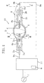
- FIG. 1 is a cross-sectional view schematically showing the configuration of a metal halide lamp of Embodiment 1 according to the present invention.
- FIG. 2 is a cross-sectional view taken along line II-II of FIG. 1.
- FIG. 3 is a cross-sectional view taken along line III-III of FIG. 1.
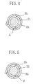
- FIG. 4 is a cross-sectional enlarged view of a principal portion of a variation of the metal halide lamp of Embodiment 1.
- FIG. 5 is a cross-sectional enlarged view of a principal portion of a variation of the metal halide lamp of Embodiment 1.
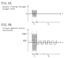
- FIG. 6A is a graph schematically showing the waveform of the current flowing the trigger wire.
- FIG. 6B is a graph schematically showing the waveform of the voltage applied to a pair of electrodes.
- FIG. 7 is a view schematically showing the configuration of a high-intensity discharge lamp operating apparatus of Embodiment 2.
- FIG. 8A is a graph schematically showing the waveform of the current flowing the trigger wire.
- FIG. 8B is a graph schematically showing the waveform of the voltage applied to a pair of electrodes.
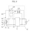
- FIG. 9 is a view schematically showing the configuration of a variation of the high-intensity discharge lamp operating apparatus of Embodiment 2.
- FIG. 10 is a view schematically showing the configuration of a variation of the high-intensity discharge lamp operating apparatus of Embodiment 2.
- FIG. 11 is a cross-sectional view showing the configuration of a conventional metal halide lamp.
- FIG. 1 is a schematic view of cross-sectional configuration of a high-intensity discharge lamp of this embodiment.
- FIG. 2 is cross-sectional view taken along line II-II of FIG. 1
- FIG. 3 is cross-sectional view taken along line III-III of FIG. 1.
- a high-intensity discharge lamp 10 of this embodiment is a metal halide lamp including a metal halide as the luminous material.
- the metal halide lamp 10 shown in FIG. 1 includes an arc tube (luminous bulb) 1 in which a pair of electrodes 3a and 3b are opposed to each other, and electrode sealing portions 2a and 2b for sealing both ends of the arc tube 1.
- the arc tube 1 in this embodiment is a spheroidal transparent vessel made of quartz glass, and the inside of the vessel constitutes a discharge space.
- the outer diameter of the central portion of the arc tube 1 is 6.0mm, the thickness is 1.6mm, and the inner volume is 0.025cc.
- the high-intensity discharge lamp 10 of this embodiment is a so-called mercury-free metal halide lamp. It is of course possible that it can be used not only for a mercury-free metal halide lamp, but also for a mercury-containing metal halide lamp enclosing mercury.
- the start-up voltage tends to be higher in the mercury-free metal halide lamp than in the mercury-containing metal halide lamp. Therefore, it is more advantageous to apply the configuration with the trigger wire 8 to the mercury-free metal halide lamp. In other words, the effect of the trigger wire 8 on the reduction in the start-up voltage can be more significant.
- a halide of indium e.g., InI 3 and/or InI, preferably InI 3
- a metal halide of indium e.g., InI 3 and/or InI, preferably InI 3
- the metal halide lamp 10 emits light having an emission spectrum in the visible light region because of light emission of the metal halides in the arc tube 1.
- Na of the NaI is a very preferable luminous material in that the emission spectrum in a visible light region can be achieved
- an alkaline metal having a small ion radius such as Na tends to move in the quartz glass and leak out of the arc tube in the configuration of the conventional metal halide lamp provided with a trigger wire (FIG. 11 ).
- a trigger wire it was difficult to use an alkaline metal halide as the metal halide in view of the lamp lifetime.
- the electrodes 3a and 3b provided in the arc tube 1 are tungsten electrodes.
- the distance between the electrodes 3a and 3b is set to, for example, 3.7mm.
- the pair of electrodes 3a and 3b are connected to external leads 5a and 5b via metal foils 4a and 4b provided in electrode sealing portions 2a and 2b.
- the electrodes sealing portions 2a and 2b are formed of quartz glass and have a pinch seal structure.
- the cross-sectional contour thereof is substantially rectangular, as shown in FIG. 3.
- the electrode sealing portions 2a and 2b can be of a shrink seal structure. In that case, the cross-sectional contour is substantially circular, for example.
- the external lead wires 5a and 5b electrically connected to the pair of electrodes 3a and 3b are electrically connected to an operating circuit (driving device) 11 including a ballast 6 via wires 9a and 9b.
- the operating circuit 11 can output a high-voltage pulse voltage (start-up voltage) for start-up and a driving voltage (lighting operation voltage) for lighting operation, and is electrically connected to a power supply 7. More in detail, the operating circuit 11 outputs a high-voltage pulse voltage for starting the lamp, and then controls the current flowing through the metal halide lamp 10 so as not to flow at a predetermined amount or more during operation.
- a high-voltage pulse voltage of 20kV is output for a predetermined period that is preset by, for example, a timer (not shown) to start the lamp, whereas during operation, a voltage of 65V and a current of 0.54A are output at a frequency of 150Hz, so that the metal halide lamp 10 is turned on with a lamp power of 35W.
- the trigger wire 8 is turned to be conductive with the electrode 3b when the start-up voltage is applied across the pair of electrodes 3a and 3b.
- the relationship of the trigger wire 8 and the electrode 3b is changed from an insulating state to a conductive state when the start-up voltage is applied.
- the second end 8b of the trigger wire 8 is arranged close to the lead wire 5b in an insulating state (air insulation), and air is present as an insulator between the former and the latter ( 8b and 5b ).
- This configuration causes insulation breakdown between the second end 8b of the trigger wire 8 and the lead wire 5b when a predetermined voltage (high-voltage pulse voltage) is applied across the external lead wire 5a and 5b from the operating circuit 11, and thus the second end 8b and the lead wire 5b have the same electric potential.
- a predetermined voltage high-voltage pulse voltage
- the trigger wire 8 becomes conductive with the electrode 3b via the external lead wire 5b.
- the distance d between the second end 8b of the trigger wire 8 and the external wire 5b is for example, less than 3mm, preferably about 1mm.
- the second end 8b of the trigger wire 8 can be spaced away from the external wire 5b, by fixing the second end 8b of the trigger wire 8 to the external wire 5b with, for example, an insulating fixing member.
- Insulation can be achieved, not only by the air 20, but also by keeping the gap between the second end 8b of the trigger wire 8 and the external wire 5b in a vacuum state.
- an insulating tape 21 can be wound around the external lead wire 5b. This configuration makes it possible to adjust the distance d easily by the number of winding of the tape 21.
- the external lead wire 5b can be covered with a ceramic cylinder 22, and the second end 8b can be wound around the outer circumference of the cylinder with about one winding. In these cases, the distance d can be the same as in the case of the air insulation.
- the first end 8a of the trigger wire 8 is wound around a region between the arc tube 1 and the sealing portion 2a, as shown in FIG. 3.
- the metal halide lamp 10 has a winding portion 8a for the trigger wire 8 at the end portion (near the base) of the sealing portion 2a on the arc tube 1 side.
- the first end 8a of the trigger wire 8 and the electrode 3a sealed in the electrode sealing portion 2a are closely positioned with a distance of about 1mm (the shortest distance) via the quartz glass of electrode sealing portion 2a.
- FIG. 6A is a graph schematically showing the waveform of the current flowing the trigger wire 8.
- FIG. 6B is a graph schematically showing the waveform of the voltage applied to the pair of electrodes 3a and 3b.
- a high-voltage pulse voltage of 20kV is output from the operating circuit 11 and applied across the electrodes 3a and 3b, as shown in FIG. 6B.
- the distance d between the external lead wire 5b and the second end 8b of the trigger wire 8 is comparatively short (e.g., about 1mm), so that when a high-voltage pulse voltage is applied, insulation therebetween is broken, and the trigger wire 8 has the same electric potential as that of the electrode 3b, as shown in FIG. 6A.
- an electrical field having a larger electric potential gradient than that between the electrodes 3a and 3b occurs in the vicinity between the first end 8a of the trigger wire 8 and the electrode 3a. Therefore, the insulation breakdown of Xe gas in the arc tube 1 is facilitated, and insulation breakdown readily occurs between the electrodes 3a and 3b.
- the metal halide lamp is turned on (or discharge is started) reliably.
- This on-state is maintained stably once started, even if the voltage is reduced.
- the on-state is maintained stably.
- the electric potential of the trigger wire 8 is in a floating state.
- the trigger wire 8 (in particular, the first end 8a ) is provided, so that a comparatively low high-voltage pulse voltage of about 20kV can start the metal halide lamp 10 reliably.
- the compactness and the reduction of the production cost of the operating circuit 11 can be achieved easily.
- the trigger wire 8 since the trigger wire 8 has the configuration as shown above at the second end 8b, an electrical field due to the trigger wire 8 does not occur during lamp operation. Therefore, the leakage of the luminous material due to the influence of the electrical field can be prevented. As a result, color change due to the reduction of the luminous material or the increase of the lamp voltage can be prevented.
- the metal halide lamp 10 having stable characteristics and a long lifetime can be realized.
- the inventors of the present invention measured the breakdown voltage with respect to the metal halide lamp 10 provided with the trigger wire 8 of Embodiment 1 and a metal halide lamp without the trigger wire 8.
- the metal halide lamp without the trigger wire 8 has the same configuration as that of the metal halide lamp 10 except that the trigger wire 8 is not provided.
- the breakdown voltage was measured in the following manner. In starting the operation of the metal halide lamps by applying a high-voltage pulse voltage to the lamps, when the breakdown occurs between the electrodes 3a and 3b to start discharge, then the voltage across the electrodes 3a and 3b is significantly dropped at the moment the lamp is turned on. Using this phenomenon, the peak voltage at this time was measured as the breakdown voltage necessary for insulation breakdown. In the case where this measurement is repeated, the metal halide lamp 10 is left undisturbed for 15 minutes or more after turned off, and then the lamp operation is started again in the state where the lamp is sufficiently cold in order to eliminate the influence of the temperature.
- Table 1 shows the measurement results of the breakdown voltage. In the case where the trigger wire 8 is provided, the distance d between the second end 8b and the external lead wire 5b is 1mm. Table 1 also shows the measurement result of the metal halide lamp of Embodiment 2 described later. Lamps for measurement Breakdown voltage (kV) Metal halide lamp of Embodiment 1 12.3 Metal halide lamp of Embodiment 2 12.2 Metal halide lamp without trigger wire 20.8
- the breakdown voltage of the metal halide lamp without the trigger wire 8 is 20.8kV
- the breakdown voltage of the metal halide lamp provided with the trigger wire 8 is 12.3kV, which is significantly reduced.
- a breakdown voltage of about 15kV or less the lamp can be started reliably under commonly used conditions.
- a high-voltage pulse voltage of about 20kV or less only needs to be applied from the operating circuit 11.
- the operating circuit 11 generating a high-voltage pulse voltage of about 20kV or less can easily achieve compactness and low cost of the circuit, and can provide high utility in the current market.
- the measured breakdown voltage is 20.8kV, and therefore it is necessary to apply a high-voltage pulse voltage exceeding 20kV.
- An operating circuit generating such a high high-voltage pulse voltage has to be produced in a special specification, and the circuit configuration becomes large-scale because components having a high withstand voltage are used, thus leading to high cost. Therefore, such a metal halide lamp has low utility in the market.
- the inventors of the present invention conducted a test as follows.
- the distance d (shortest distance) between the second end 8b of the trigger wire 8 and the external lead wire 5b in the metal halide lamp 10 of this embodiment is set to various values in the range from 0.5mm to 4mm, and a high-voltage pulse voltage of 15kV is applied to start the lamp in the same manner as described above.
- Table 2 shows the results of the test to start the lamp. This test was conducted with the configuration where the insulating tape 21 is provided as shown in FIG. 4.
- Distance d (mm) 0.5 1.0 1.5 2.0 2.5 3.0 3.5 4.0 Starting Test results
- the lamp when the distance d between the second end 8b of the trigger wire 8 and the external lead wire 5b was less than 3mm (e.g., 2.5mm to 0.5mm), the lamp was turned on reliably. However, in the case of 3mm or more, the lamp was not turned on. The reason why the lamp was not turned on seems be that when the distance d is large, insulation breakdown does not occur, so that the electric potential of the trigger wire 8 is not the same as that of the external lead wire 5b. In general and regular lamps, by setting the distance d to less than 3mm, the start-up properties can be satisfactory. However, the distance d is not limited thereto, and can be set as appropriate, depending on various conditions.
- the distance d can be set suitably such that insulation breakdown occurs only when a high-voltage pulse voltage is applied.
- the second end 8b of the trigger wire 8 is not necessarily disposed close to the external lead wire 5b, but can be disposed close to a portion to which a high voltage for starting the lamp is applied, such as a wire 9b. Furthermore, the end of the trigger wire 8 is not necessarily disposed close to the external lead wire 5b, but the other portions such as the center of the trigger can be disposed close thereto.
- the inventors of the present invention conducted a test regarding the lamp lifetime with respect to the metal halide lamp 10 (see FIG. 1 ) of this embodiment where the second end 8b of the trigger wire 8 is disposed close to the external lead wire 5b and a metal halide lamp where the trigger wire 108 is connected to one of the external lead wires 105b, and has the same electric potential as that of one of the electrodes 103b constantly, even during lamp operation (Comparative Example; see FIG. 11 regarding the configuration of the trigger wire 108 ).
- the constitutions of the enclosed materials are the same in the two lamps.
- the influence of the trigger wire was examined with the two lamps that has been on for 250 hours. Table 3 shows the results of the lifetime test.
- Table 3 shows a typical example of ten tests of each lamp. change after initial test Lamps for measurement Color temperature (K) Lamp voltage (V) Luminous flux maintenance factor (%) Devitrification Metal halide lamp 4000 ⁇ 4300 67 ⁇ 67 98 Not observed Comparative Example 4000 ⁇ 6500 60 ⁇ 120 50 Observed
- the electric potential of the trigger wire 8 is in a floating state during lamp operation. Therefore, an electrical field having a large electric potential gradient is not formed, so that the luminous material does not leak out. As a result, the change in the color temperature, the increase in the lamp voltage and the reduction in the luminous flux maintenance factor hardly occur, and devitrification does not occur in the arc tube 1. Consequently, a long lifetime of the lamp can be achieved.
- the metal halide lamp 10 having a long lamp lifetime can be provided. More in detail, discharge readily occurs between the pair of electrodes 3a and 3b by the influence of the electrical field formed between the trigger wire 8 and the electrode 3a by establishing the conductive state between the trigger wire 8 and the electrode 3b during the start-up. Therefore, a comparatively low voltage easily can start the lamp operation.
- the trigger wire 8 and the electrode 3b is in the conductive state only during the start-up, and during operation, a large electrical field does not occur in the vicinity of the trigger wire 8. Consequently, the ionized material (e.g., sodium ions) enclosed in the arc tube 1 is not attracted to the trigger wire 8, does not move inside the bulb wall of the arc tube 1 nor leaks out. Therefore, the amount of the enclosed material is not reduced, or the amorphous structure is not broken, which might occur when ions are moving inside the bulb wall of the arc tube. Therefore, the change in the color temperature, the increase in the lamp voltage, the reduction in the luminous flux maintenance factor, the devitrification of the arc tube are not caused and a long lifetime of the lamp can be achieved.
- the ionized material e.g., sodium ions
- the trigger wire 8 when the trigger wire 8 is provided with a close portion ( 8b ) to the external lead wire 5b, and a start-up voltage (high-voltage pulse voltage) is applied during the start-up, then a high voltage is applied to the trigger wire 8 because of insulation breakdown. Therefore with a simple configuration, the reduction of the breakdown voltage and the effect of prevention of the lamp characteristics change can be obtained.
- a switching element can be used to connect the trigger wire 8 to a high voltage power supply only during the start-up.
- the electric potential of the trigger wire 8 is the same as that of the electrode 3b during the start-up.
- the present invention is not limited thereto, and the electric potential of the trigger wire 8 is not necessarily the same as that of the electrode 3b. Any electric potential can be used as long as it can start discharge between the electrodes 3a and 3b by the electrical field formed between the first end 8a and the electrode 3a.
- FIG. 7 schematically shows the circuit configuration of a high-intensity discharge lamp operating apparatus of the present invention.
- the high-intensity discharge lamp operating apparatus shown in FIG. 7 includes a metal halide lamp 13 and an operating circuit 12 for operating the metal halide lamp 13.
- a high-voltage pulse voltage is applied to the trigger wire 8 wound around the lamp 13 only during the start-up.
- this embodiment is different from Embodiment 1 in that a high-voltage pulse voltage for the start-up is applied only to the trigger wire 8, and the same voltage (driving voltage) as during operation is applied across the pair of electrodes 3a and 3b of the lamp during the start-up.
- this embodiment is different in that application of a high-voltage pulse voltage is achieved not by the insulation breakdown from the external lead wire 5b, but the control by the operating circuit (driving circuit) 12.
- Other aspects are the same as in Embodiment 1, so that description thereof will be omitted or simplified.
- the operating circuit 12 shown in FIG. 7 is different from the operating circuit 11 of Embodiment 1 in that the driving voltage for operating the lamp is output independently of the high-voltage pulse voltage for starting the lamp operation.
- the voltage for operating the lamp is output from the power supply 7 via a ballast 6 of the operating circuit 12.
- the voltage of the power supply 7 is increased by a step-up transformer 130, and output via a relay 120.
- the relay 120 is controlled by a timer circuit 110 so as to be on for a predetermined time (e.g., one second) after the start of the start-up operation.
- the metal halide lamp 13 is provided with the trigger wire 8 whose first end 8a is wound around the base of the electrode sealing portion 2a, as in the metal halide lamp 10 of Embodiment 1.
- the second end 8b of the trigger wire 8 is not provided close to the external lead wire 5b, but is electrically connected to the relay 120 of the operating circuit 12 via a wire 100.
- the external lead wire 5a and 5b are electrically connected to the ballast 6 of the operating circuit 12.
- FIG. 8A is a graph schematically showing the waveform of the voltage applied to the trigger wire 8.
- FIG. 8B is a graph schematically showing the waveform of the voltage applied across the pair of electrodes 3a and 3b.
- a high-voltage pulse voltage (e.g., 20kV) output from the step-up transformer 130 is applied to the trigger wire 8.
- a high-voltage pulse voltage (e.g., 20kV) output from the step-up transformer 130 is applied to the trigger wire 8.
- an electrical field having a large electric potential gradient occurs in the vicinity of the first end 8a of the trigger 8 inside the arc tube 1, and the insulation breakdown of Xe gas is facilitated. Therefore, with a lower start-up voltage, discharge is started with the driving voltage applied across the external lead wires 5a and 5b, and thus the lamp is turned on.
- the relay 120 When one second has passed since a start-up operation is started, the relay 120 is turned off by the control of the timer circuit 110, so that the electric potential of the trigger wire 8 is in a floating state ( T 2 ). Therefore, as in Embodiment 1 , an electrical field having a large electric potential is not formed between the trigger wire 8 and the discharge electrode during operation, so that the luminous material does not leak out. Consequently, the change in the color temperature, the increase in the lamp voltage and the reduction in the luminous flux maintenance factor hardly occur, and devitrification does not occur in the arc tube 1. Consequently, a long lifetime of the lamp can be achieved.
- a high-voltage pulse voltage is not applied across the pair of electrodes 3a and 3b, so that damages such as depletion due to melt deformation or evaporation of the electrode during the start-up can be prevented or reduced.
- the breakdown voltage was measured in the same manner as in Embodiment 1. As shown in Table 1 , the breakdown voltage was 12.2V. In other words, compared to the metal halide lamp without the trigger wire, the breakdown voltage can be reduced significantly. Furthermore, when the lifetime test was carried out, as in the metal halide lamp 10 of the Embodiment 1, the phenomenon that an alkaline metal such as sodium as the luminous material leaks out of the arc tube 1 was not observed, and it was found that stable characteristics and a long lamp lifetime can be obtained.
- FIG. 7 can be modified to the configuration shown in FIG. 9.
- FIG. 9 shows the circuit configuration of a variation of Embodiment 2.
- the control of the relay 120 for applying a high-voltage pulse voltage only during the start-up is performed by operation detecting means 150 for detecting that the lamp is turned on, instead of the timer circuit 110.
- operation detecting means 150 for example, a current detector for detecting the lamp current can be used. Describing the operation more specifically, discharge between the discharge electrodes is started by applying a high-voltage pulse voltage to the trigger wire 8. Then, for example, when a lamp current of 0.3A or more is detected by the current detector 150, the relay 120 is turned off, so that a high-voltage pulse voltage is not applied to the trigger wire 8.
- the operating circuit 15 can be configured such that a voltage detector 151 for detecting the lamp voltage is used as the operation detecting means to control the relay 120.
- the output voltage from the ballast 6 is a predetermined open circuit voltage (e.g., 350V), and when discharge is started, the lamp voltage is for example, about 65V. Utilizing this change in the voltage to detect that the lamp operation is started, a high-voltage pulse voltage can be applied to the trigger wire 8 only during the start-up.
- an optical sensor can be used.
- the arc tube 1 is made of quartz glass, but the present invention is not limited thereto and the arc tube made of a ceramics materials can be used.
- the arc tube made of a ceramic material is, so-called obscure glass, so that a point light source is difficult to achieve.
- the entire of the arc tube is luminous, so that it is difficult to obtain a point light source. Therefore, it is preferable to use the arc tube made of quartz glass for applications requiring a point light source such as a headlight of automobiles.
- the present invention has been described by taking the metal halide lamp as an example, but is not limited thereto, and the present invention can be applied to various high-intensity discharge lamp (e.g., high pressure mercury lamp) having a similar discharge mechanism.
- high-intensity discharge lamp e.g., high pressure mercury lamp
- the advantage is large when the present invention is applied to metal halide lamps, but the present invention can be applied suitably to other high-intensity discharge lamps (HID) such as high pressure mercury lamps, high pressure sodium lamps or the like.
- HID high-intensity discharge lamps
- the xenon gas pressure, the inner volume of the arc tube 1 , the distance between the electrodes, a combination of metal halides such as scandium iodide and sodium iodide in the above embodiments are only illustrative. Therefore, for example, the inner volume of the arc tube 1 is not limited to 0.025cc, or the distance between the electrodes is not limited to 3.7mm. Other combinations of metal halides can be used.
- Xenon gas is enclosed in the arc tube 1 for the purpose of aiding to start the lamp operation in the above embodiments.
- xenon gas is suitable as a rare gas only in the viewpoint of an application to a headlight of automobiles, but other rare gases than xenon, for example, argon gas can be used.
- the lamp power is not limited to 35W.
- the high-intensity discharge lamp in the above embodiments can be used not only for a headlight for automobiles, but for general illumination or other applications.
- the present invention can be used as a light source for image projecting apparatus such as projectors using liquid crystal or a DMD.
- the present invention can also be used for sports stadiums or floodlights illuminating road signs.
Applications Claiming Priority (2)
| Application Number | Priority Date | Filing Date | Title |
|---|---|---|---|
| JP2000169656 | 2000-06-06 | ||
| JP2000169656 | 2000-06-06 |
Publications (2)
| Publication Number | Publication Date |
|---|---|
| EP1162865A2 true EP1162865A2 (de) | 2001-12-12 |
| EP1162865A3 EP1162865A3 (de) | 2004-08-25 |
Family
ID=18672486
Family Applications (1)
| Application Number | Title | Priority Date | Filing Date |
|---|---|---|---|
| EP01113826A Withdrawn EP1162865A3 (de) | 2000-06-06 | 2001-06-06 | Entladungslampe hoher Intensität, und Gerät zum Betreiben solch einer Lampe |
Country Status (4)
| Country | Link |
|---|---|
| US (1) | US6586891B2 (de) |
| EP (1) | EP1162865A3 (de) |
| KR (1) | KR20010110200A (de) |
| CN (1) | CN1207753C (de) |
Cited By (4)
| Publication number | Priority date | Publication date | Assignee | Title |
|---|---|---|---|---|
| EP1549114A1 (de) * | 2003-12-25 | 2005-06-29 | Ushiodenki Kabushiki Kaisha | Vorrichtung zum Betrieben einer Hochdruck-Entladungslampe für ein Projektionsgerät |
| WO2008009713A1 (de) * | 2006-07-21 | 2008-01-24 | Osram Gesellschaft mit beschränkter Haftung | Entladungslampe mit zündhilfselement |
| WO2012007405A2 (de) | 2010-07-13 | 2012-01-19 | Osram Gesellschaft mit beschränkter Haftung | Hochdruckentladungslampe mit zündhilfe |
| TWI384169B (zh) * | 2009-06-18 | 2013-02-01 | Utechzone Co Ltd | A full range of street light intensity control and energy saving system based on vehicle traffic and vehicle speed detection |
Families Citing this family (13)
| Publication number | Priority date | Publication date | Assignee | Title |
|---|---|---|---|---|
| JP3938038B2 (ja) * | 2002-12-18 | 2007-06-27 | ウシオ電機株式会社 | ショートアーク型放電ランプ |
| JP4549971B2 (ja) * | 2003-03-17 | 2010-09-22 | パナソニック株式会社 | 高圧放電ランプの製造方法、高圧放電ランプおよびこの高圧放電ランプを用いたランプユニット並びに画像表示装置 |
| KR101123190B1 (ko) * | 2004-09-02 | 2012-03-19 | 코닌클리즈케 필립스 일렉트로닉스 엔.브이. | 최적화된 염류 충전재를 갖는 방전 램프 |
| JP5015799B2 (ja) * | 2005-01-03 | 2012-08-29 | コーニンクレッカ フィリップス エレクトロニクス エヌ ヴィ | 投影システムにおける水銀蒸気放電ランプの動作のための方法及び動作制御器 |
| JP5009569B2 (ja) * | 2005-10-03 | 2012-08-22 | 日清紡ホールディングス株式会社 | ソーラシミュレータとその運転方法 |
| US20080224614A1 (en) * | 2005-11-14 | 2008-09-18 | Koninklijke Philips Electronics, N.V. | Looped Frame Arc Tube Mounting Assembly for Metal Halide Lamp |
| US7271551B1 (en) * | 2006-11-22 | 2007-09-18 | Zippy Technology Corp. | Driver protection circuit for a push-pull type discharge lamp |
| JP2010524167A (ja) * | 2007-04-05 | 2010-07-15 | コーニンクレッカ フィリップス エレクトロニクス エヌ ヴィ | 無水銀高輝度ガス放電ランプ |
| DE202008009456U1 (de) * | 2008-07-14 | 2008-10-02 | Osram Gesellschaft mit beschränkter Haftung | Hochdruckentladungslampe |
| US20100033106A1 (en) * | 2008-08-08 | 2010-02-11 | Toshiba Lighting & Technology Corporation | High-pressure discharge lamp, high-pressure discharge lamp lighting system and lighting equipment |
| JP2010129280A (ja) * | 2008-11-26 | 2010-06-10 | Sanyo Electric Co Ltd | ランプ点灯装置およびそれを用いた投射型映像表示装置 |
| JP5051401B2 (ja) * | 2010-03-30 | 2012-10-17 | ウシオ電機株式会社 | 高圧放電ランプ |
| US8339044B2 (en) | 2010-12-28 | 2012-12-25 | General Electric Company | Mercury-free ceramic metal halide lamp with improved lumen run-up |
Citations (5)
| Publication number | Priority date | Publication date | Assignee | Title |
|---|---|---|---|---|
| GB596476A (en) * | 1945-07-26 | 1948-01-05 | Scophony Ltd | Improvements in electric discharge lamps |
| US3993922A (en) * | 1976-01-05 | 1976-11-23 | Gte Sylvania Incorporated | Arc discharge lamp with integral trigger electrode |
| US4047064A (en) * | 1976-06-16 | 1977-09-06 | Gte Sylvania Incorporated | Flash tube having enclosed trigger wire |
| US4207541A (en) * | 1978-02-21 | 1980-06-10 | General Electric Company | Cooling jacket for laser flash lamps |
| JPH09265947A (ja) * | 1996-03-29 | 1997-10-07 | Ushio Inc | メタルハライドランプ |
Family Cites Families (16)
| Publication number | Priority date | Publication date | Assignee | Title |
|---|---|---|---|---|
| US4179640A (en) * | 1977-12-05 | 1979-12-18 | Westinghouse Electric Corp. | Hid sodium lamp which incorporates a high pressure of xenon and a trigger starting electrode |
| JPS56132760A (en) | 1980-03-19 | 1981-10-17 | Toshiba Corp | Metal vapor discharge lamp |
| JPS6074257A (ja) | 1983-09-30 | 1985-04-26 | Toshiba Corp | 高圧ナトリウムランプ |
| US4721888A (en) * | 1984-12-27 | 1988-01-26 | Gte Laboratories Incorporated | Arc discharge lamp with ultraviolet enhanced starting circuit |
| US4992703A (en) * | 1986-04-14 | 1991-02-12 | North American Philips Corp. | Metal halide lamp with dual starting electrodes and improved maintenance |
| JPH0554983A (ja) | 1991-08-28 | 1993-03-05 | Mitsubishi Electric Corp | 放電灯点灯装置 |
| JPH0684504A (ja) | 1992-09-01 | 1994-03-25 | Hitachi Ltd | 起動補助装置内蔵放電ランプ |
| JP2923146B2 (ja) | 1992-11-25 | 1999-07-26 | 株式会社小糸製作所 | 放電ランプ装置用アークチューブ |
| JPH06333684A (ja) | 1993-05-20 | 1994-12-02 | Matsushita Electric Ind Co Ltd | 放電灯点灯装置 |
| JPH0869777A (ja) | 1994-08-30 | 1996-03-12 | Iwasaki Electric Co Ltd | ショートアークメタルハライドランプ及びそれを用いた光学装置 |
| JP3224993B2 (ja) | 1996-11-05 | 2001-11-05 | 松下電器産業株式会社 | 高圧放電ランプ及びその製造方法 |
| JP3208087B2 (ja) | 1997-04-18 | 2001-09-10 | 松下電器産業株式会社 | メタルハライドランプ |
| JPH11238488A (ja) | 1997-06-06 | 1999-08-31 | Toshiba Lighting & Technology Corp | メタルハライド放電ランプ、メタルハライド放電ランプ点灯装置および照明装置 |
| DE19731168A1 (de) | 1997-07-21 | 1999-01-28 | Patent Treuhand Ges Fuer Elektrische Gluehlampen Mbh | Beleuchtungssystem |
| JP3489414B2 (ja) | 1997-09-30 | 2004-01-19 | ウシオ電機株式会社 | ショートアーク型放電ランプ |
| JP2001357987A (ja) | 2000-06-14 | 2001-12-26 | Matsushita Electric Ind Co Ltd | 冷陰極蛍光放電管の駆動方法 |
-
2001
- 2001-06-05 US US09/874,779 patent/US6586891B2/en not_active Expired - Lifetime
- 2001-06-05 KR KR1020010031316A patent/KR20010110200A/ko not_active Application Discontinuation
- 2001-06-06 CN CNB011159383A patent/CN1207753C/zh not_active Expired - Fee Related
- 2001-06-06 EP EP01113826A patent/EP1162865A3/de not_active Withdrawn
Patent Citations (5)
| Publication number | Priority date | Publication date | Assignee | Title |
|---|---|---|---|---|
| GB596476A (en) * | 1945-07-26 | 1948-01-05 | Scophony Ltd | Improvements in electric discharge lamps |
| US3993922A (en) * | 1976-01-05 | 1976-11-23 | Gte Sylvania Incorporated | Arc discharge lamp with integral trigger electrode |
| US4047064A (en) * | 1976-06-16 | 1977-09-06 | Gte Sylvania Incorporated | Flash tube having enclosed trigger wire |
| US4207541A (en) * | 1978-02-21 | 1980-06-10 | General Electric Company | Cooling jacket for laser flash lamps |
| JPH09265947A (ja) * | 1996-03-29 | 1997-10-07 | Ushio Inc | メタルハライドランプ |
Non-Patent Citations (1)
| Title |
|---|
| PATENT ABSTRACTS OF JAPAN vol. 1998, no. 02, 30 January 1998 (1998-01-30) -& JP 09 265947 A (USHIO INC), 7 October 1997 (1997-10-07) * |
Cited By (7)
| Publication number | Priority date | Publication date | Assignee | Title |
|---|---|---|---|---|
| EP1549114A1 (de) * | 2003-12-25 | 2005-06-29 | Ushiodenki Kabushiki Kaisha | Vorrichtung zum Betrieben einer Hochdruck-Entladungslampe für ein Projektionsgerät |
| US7138769B2 (en) | 2003-12-25 | 2006-11-21 | Ushiodenki Kabushiki Kaisha | Device for operation of a high pressure discharge lamp and a projector device |
| WO2008009713A1 (de) * | 2006-07-21 | 2008-01-24 | Osram Gesellschaft mit beschränkter Haftung | Entladungslampe mit zündhilfselement |
| TWI384169B (zh) * | 2009-06-18 | 2013-02-01 | Utechzone Co Ltd | A full range of street light intensity control and energy saving system based on vehicle traffic and vehicle speed detection |
| WO2012007405A2 (de) | 2010-07-13 | 2012-01-19 | Osram Gesellschaft mit beschränkter Haftung | Hochdruckentladungslampe mit zündhilfe |
| DE102010031280A1 (de) | 2010-07-13 | 2012-01-19 | Osram Gesellschaft mit beschränkter Haftung | Hochdruckentladungslampe mit Zündhilfe |
| US8618734B2 (en) | 2010-07-13 | 2013-12-31 | Osram Ag | High-pressure discharge lamp with ignition aid |
Also Published As
| Publication number | Publication date |
|---|---|
| CN1207753C (zh) | 2005-06-22 |
| CN1327256A (zh) | 2001-12-19 |
| US6586891B2 (en) | 2003-07-01 |
| US20020163315A1 (en) | 2002-11-07 |
| EP1162865A3 (de) | 2004-08-25 |
| KR20010110200A (ko) | 2001-12-12 |
Similar Documents
| Publication | Publication Date | Title |
|---|---|---|
| US6586891B2 (en) | High-intensity discharge lamp and high-intensity discharge lamp operating apparatus | |
| US5117160A (en) | Rare gas discharge lamp | |
| EP0313027B1 (de) | Bogenentladungslampe mit ultraviolettstrahlender Entzündungsquelle | |
| JP3208087B2 (ja) | メタルハライドランプ | |
| US6608444B2 (en) | Mercury-free high-intensity discharge lamp operating apparatus and mercury-free metal halide lamp | |
| JP2008135194A (ja) | 光源装置 | |
| JPH01134849A (ja) | 無電極の紫外線始動源を備えたアーク放電ランプ | |
| US4491766A (en) | High pressure electric discharge lamp employing a metal spiral with positive potential | |
| JPS64785B2 (de) | ||
| JP3385013B2 (ja) | 高輝度放電灯および高輝度放電灯点灯装置 | |
| CN101720494B (zh) | 高压钠灯 | |
| JP3221228B2 (ja) | 高圧放電ランプ | |
| US4376259A (en) | High intensity discharge lamp including arc extinguishing means | |
| JP3638719B2 (ja) | セラミックス放電ランプ,ランプ装置,点灯装置および液晶プロジェクター | |
| JPH03225745A (ja) | 希ガス放電灯 | |
| WO2005055272A2 (en) | High-pressure discharge lamp assembly | |
| JP3143984B2 (ja) | 高圧放電灯点灯装置 | |
| EP1001451B1 (de) | Barium enthaltende Bogenentladungslampe mit einer Bogenröhre aus Yttrium-, Gadolinium- oder Terbiumoxide | |
| JPH02301953A (ja) | メタルハライドランプ | |
| JP3409373B2 (ja) | ソレノイド磁界式放電灯 | |
| JPH0244448Y2 (de) | ||
| JP3498320B2 (ja) | 高圧放電灯および高圧放電灯装置 | |
| JPS59180955A (ja) | 高圧金属蒸気放電灯 | |
| JPH01243362A (ja) | 小型蛍光ランプ | |
| JPH05217559A (ja) | 外部電極放電ランプ |
Legal Events
| Date | Code | Title | Description |
|---|---|---|---|
| PUAI | Public reference made under article 153(3) epc to a published international application that has entered the european phase |
Free format text: ORIGINAL CODE: 0009012 |
|
| AK | Designated contracting states |
Kind code of ref document: A2 Designated state(s): AT BE CH CY DE DK ES FI FR GB GR IE IT LI LU MC NL PT SE TR |
|
| AX | Request for extension of the european patent |
Free format text: AL;LT;LV;MK;RO;SI |
|
| PUAL | Search report despatched |
Free format text: ORIGINAL CODE: 0009013 |
|
| AK | Designated contracting states |
Kind code of ref document: A3 Designated state(s): AT BE CH CY DE DK ES FI FR GB GR IE IT LI LU MC NL PT SE TR |
|
| AX | Request for extension of the european patent |
Extension state: AL LT LV MK RO SI |
|
| AKX | Designation fees paid | ||
| STAA | Information on the status of an ep patent application or granted ep patent |
Free format text: STATUS: THE APPLICATION IS DEEMED TO BE WITHDRAWN |
|
| REG | Reference to a national code |
Ref country code: DE Ref legal event code: 8566 |
|
| 18D | Application deemed to be withdrawn |
Effective date: 20041231 |