EP1162775A2 - Verfahren zur Kodierung/Dekodierung von einem Fehlerkorrekturkode, Übertragungseinrichtung und Netzwerk - Google Patents
Verfahren zur Kodierung/Dekodierung von einem Fehlerkorrekturkode, Übertragungseinrichtung und Netzwerk Download PDFInfo
- Publication number
- EP1162775A2 EP1162775A2 EP01102059A EP01102059A EP1162775A2 EP 1162775 A2 EP1162775 A2 EP 1162775A2 EP 01102059 A EP01102059 A EP 01102059A EP 01102059 A EP01102059 A EP 01102059A EP 1162775 A2 EP1162775 A2 EP 1162775A2
- Authority
- EP
- European Patent Office
- Prior art keywords
- signal
- code
- client
- signals
- super fec
- Prior art date
- Legal status (The legal status is an assumption and is not a legal conclusion. Google has not performed a legal analysis and makes no representation as to the accuracy of the status listed.)
- Withdrawn
Links
Images


Classifications
-
- H—ELECTRICITY
- H04—ELECTRIC COMMUNICATION TECHNIQUE
- H04L—TRANSMISSION OF DIGITAL INFORMATION, e.g. TELEGRAPHIC COMMUNICATION
- H04L1/00—Arrangements for detecting or preventing errors in the information received
- H04L1/0078—Avoidance of errors by organising the transmitted data in a format specifically designed to deal with errors, e.g. location
- H04L1/0083—Formatting with frames or packets; Protocol or part of protocol for error control
Definitions
- the present invention relates to a method for encoding/decoding an error correcting code, a transmitting apparatus and a network which are suitable for use in optical communication networks.
- the optical fiber communication capable of transmitting a large capacity of data employs relatively high quality transmission paths implemented by optical fibers as media which generally exhibit a bit error ratio below 10 -10 .
- a redundancy configuration which comprises protection optical fibers as well as working optical fibers, can realize switching of paths when a signal degradation occurs. For this reason, the optical fiber communication has been systematically constructed on the assumption that no error correcting code is used.
- An exceptional introduction of an error correcting code into the optical fiber communication is an application of an eight-error-correcting Reed-Solomon code (255, 239) to a frame format defined by ITU-T in Recommendation G.975 (established in 1996) for a submarine optical transmission system. Also, a known example is JP-A-62-221223.
- TDM time division multiplexing
- WDM wavelength division multiplexing
- the transmittable distance is reciprocally proportional to a square root of the degree of multiplexing for a fixed transmission optical power due to the variance and nonlinearity possessed by an optical fiber, the transmittable distance is reduced to one quarter when the degree of multiplexing becomes twice higher.
- This reduction corresponds to a degradation loss of 6 dB, so that a compensation for the loss of 6 dB or more is required for increasing the transmission capacity twice as much through the time division multiplexing while the transmission distance is maintained.
- a coding gain of 6 dB or more is needed for making this compensation for the loss using an error correcting code. Since the gain of the eight-error-correcting Reed-Solomon code is 5.4 dB for a bit error ratio of 10 -12 in consideration of an increase in the transmission rate by approximately 7 %, this error correcting code alone is not sufficient to realize the above-mentioned double increase of the transmission capacity.
- the degree of wavelength division multiplexing becomes higher, this causes closer wavelength intervals of a plurality of optical signals transmitted through a single optical fiber core line, a degraded separation, and a resulting reduction in the transmission distance, similarly to the aforementioned case.
- the transmission distance is limited when all of bit rates at respective wavelengths are not the same. Specifically, since the transmission distance is determined by the highest bit rate, an optical signal at a low bit rate can be used only within a limited transmission distance although it can be transmitted to more distant locations.
- bit rates of a plurality of optical signals transmitted through a single optical fiber core line may differ depending on the generation, the ratio is approximately two in many cases when viewed within a certain period. Therefore, for reasons similar to the aforementioned example, a high bit rate signal must be compensated for a loss of 6 dB or more in order to maximally extend a transmission distance when optical signals at different bit rates are mixed in the wavelength division multiplexed transmission. However, the eight-error-correcting Reed-Solomon code alone is not sufficient to realize such a compensation.
- regenerator interval when the distances between regenerators and between a regenerator and an end terminal (hereinafter simply called the "regenerator interval"), for electrically reproducing digital signals, are increased to reduce the number of the regenerators with the intention of reducing the cost associated with the construction of a network at the cost of an increase in the transmission capacity, the signal quality is more degraded as the regenerator interval is longer. For example, when the regenerator interval is increased four times, a compensation for a loss of 6 dB or more is required, in which case the eight-error-correcting Reed-Solomon code alone is not sufficient to realize such a compensation.
- the widespreading Internet communications increase a demand for the so-called Giga bits Ether signal of 1000 Base-SX, 1000 Base-LX, 1000 Base-XC defined by IEEE (Institute of Electrical and Electronics Engineers, Inc.) in Standard 802.3z, resulting in requirements for the transmission of the Giga bits Ether signals over a section of a long distance within a local network and a backbone network which accommodate the Giga bits Ether signals as optical signals.
- the Giga bits Ether signal uses a retransmission requesting scheme called ARQ (Auto Repeat Request) based on an end-to-end communication on a higher layer than a link layer, the Giga bits Ether signal comprises no error correcting code.
- An error correcting scheme defined in Recommendation G.975 involves parallellizing an STM-16 signal of SDH having a bit rate of 2.48832 Gbit/s on a bit-by-bit basis, dividing the STM-16 signal into (8 ⁇ n) subframes each having a length of 238 bits, encoding every eight subframes to an eight-error-correcting Read-Solomon code (255, 239), adding a check bit and information for framing structure to the resulting codes, converting the subframes such that each subframe has 255 bits, interleaving the converted (8 ⁇ n) subframes on a bit-by-bit basis, and finally constructing an FEC frame having a bit rate of approximately 2.666 Gbit/s.
- the value of the above "n" is often set to 16 for facilitating the configuration of an encoder and a decoder, in which case, the processing rate is approximately 21 (exactly 19.44 ⁇ 255/238) Mbit/s for each of the subframes.
- the signal must be divided into four signals corresponding to STM-16 in parallel.
- the error correcting scheme according to Recommendation G.975 defines the STM-16 signal as a minimum unit. In this event, therefore, the value of the aforementioned "n" is increased by a factor of four from 16 to 64, so that the processing speed in the encoder and the decoder is the same as approximately 21 Mbit/s as mentioned above, where, however, the scale must be increased four times.
- the present invention provides a method for encoding/decoding an error correcting code which has a gain sufficient to address a double increase in the degree of time division multiplexing of optical signals transmitted through a single-core optical fiber; maintenance of an original transmission distance when such optical signals are wavelength multiplexed; and realization of a increase in a regenerator interval of optical signals by a factor of four, a transmitting apparatus using the method, and a network.
- a client signal having a constant bit rate is segmented every a bytes to create code information blocks.
- the bit rate of the client signal is increased such that it has the code information block and an empty area of b bytes, and the ratio c/a is equal to or higher than 110 % to create a code block 3 comprised of c bytes.
- the code information block in the code block is encoded such that an error correcting code is included therein to have an encoding gain of 6dB or higher for a bit error ratio of 10 -12 .
- Associated check bits are placed in the empty area to eventually generate a super FEC signal.
- a client signal having a constant bit rate is segmented every (Kr ⁇ Kc) bytes to create an information block 100.
- the bit rate of the information block 100 is increased by a factor of ⁇ Nr ⁇ Nc)/(Kr ⁇ Kc) ⁇ to create an coded block 130 comprised of (Nr ⁇ Nc) bytes.
- the information block 100 is interleaved every arbitrary ⁇ bytes Kr times, and placed within (Kr rows ⁇ Kc columns) in the coded block 130 to create empty areas 110B, 110C, 120B.
- C1-encoding k-error-correction encoding
- ⁇ Nr ⁇ Nc)/(Kr ⁇ Kc) ⁇ is scaled to fall within a range of 110 % to 130 % in percentage notation, and the C1-encoding and the C2-encoding are combined to generate pseudo product codes or concatenated codes to provide a super FEC signal which has an encoding gain of 6 dB or higher for a bit error ratio of 10 -12 .
- the same frame structure is employed irrespective of the type of client signal.
- a signal applicable to an embodiment may be a signal which has a fixed bit rate and can be segmented into code blocks of a fixed length, and an error correcting code applied thereto may be a systematic signal.
- SDH- or SONET-based transmission signal is a signal formatted in frames at a cycle of 125 microseconds, and can be arbitrarily segmented into code blocks of a fixed length, so that this signal satisfies the foregoing definition.
- a Reed-Solomon code is defined as a code on Galois field (256), and a BCH code as a binary BCH code. Also, the Reed-Solomon code is abbreviated as the "RS code” for simplification.
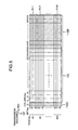
- Figs. 1 and 2 show an information data area and an encoded area in a frame structure.
- the following description is directed to an encoding side which receives a client signal from a transmission path on a client side, error-correction-encodes the client signal, and then transmits the resulting signal to a super line side as a super FEC signal.
- the client signal may be either an electric signal or an optical signal in practice, it is assumed herein that, when an optical signal is concerned, the optical signal converted to an electric signal is the client signal.
- a client signal having serial bits arranged on a time series basis is segmented into blocks of (KrxKc) bytes (called the "first coded information block"), and each of the first coded information blocks is parallelly expanded in Kr stages every predetermined consecutive bytes (every ⁇ bytes).
- a blank area 100 in Fig. 1 represents parallelly expanded first coded information blocks.
- Each rectangle field in Fig. 1 indicates one byte, wherein bits in each byte may be oriented in the row direction or in the column direction. Bits oriented in the row direction indicate a parallel expansion of Kr bits, while bits oriented in the column direction indicate a parallel expansion of (Kr ⁇ 8) bits.
- the first coded information blocks are treated as the parallel expansion in a Kr stage, irrespective of the orientation of bits within a byte, however, with bits oriented in the column direction, (Kr ⁇ 8) may be newly processed as Kr in a manner similar to the following.
- the parallel expansion may be organized in a sequence such that ⁇ consecutive bytes on a serial client signal are mapped to serial ⁇ bytes on the first row in Fig. 1, the next continuous ⁇ bytes on the client signal are mapped to ⁇ serial bytes on a second row, and so on.
- the value of ⁇ may be arbitrary as long as it is a divisor of Kc.
- the value of ⁇ may be one, or the number of bytes for the interleaving in the multiplexing rule when the client signal is a SONET/SDH signal.
- every ⁇ bits may be mapped instead of every ⁇ bytes.
- Fig. 20 shows a relationship between sequences of serial bits and bits of the client signal and those of a parallel signal.
- Kc* indicates a value derived by dividing Kc by ⁇ .
- Fig. 20 shows the relationship between sequences of bits and bytes of data when a client signal is converted into a parallellized client signal, and vice versa.
- ⁇ consecutive bytes (#1-1) on the serial client signal are mapped to ⁇ serial bytes (#1-1) of the first row in a parallel signal, and subsequently, every ⁇ consecutive bytes (#2-1, #3-1, ..., #Kr-1) on the serial client signal are mapped to every ⁇ bytes (#2-1, #3-1, ..., #Kr-1) on second through Kr-th rows of the parallel signal to arrange the (Kr ⁇ ⁇ ) consecutive bytes on the serial client signal in Kr parallel rows.
- subsequent (Kr ⁇ ) consecutive bytes on the serial client signal are also arranged in Kr parallel rows.
- the respective rows are simultaneously transmitted in an apparatus of interest.
- a first coded information block signal of the parallelly expanded (Kr ⁇ Kc) bytes is received, and its bit rate is increased by a factor of (Nc/Kc) to create an empty area of ⁇ Kr ⁇ (Nc-Kc) ⁇ bytes.
- Areas 110B, 110C indicated by rightwardly inclining hatchings in Fig. 1 correspond to the empty area.
- Nc is an arbitrary integer value, for example, 255.
- a ⁇ -error-correcting RS code (na, ka) or an ⁇ -error-correcting BCH code (nb, kb) may be used.
- the notation of an RS code generally refers to a symbol having a code length equal to na; a symbol having an information length equal to nb; and a symbol having (na-nb) check bits, wherein one symbol is one byte long in the case of a code on Galois field (256).
- the notation of a BCH code (nb, kb) means that the code length is nb bits; the information length is kb bits; and the check bits has a length of (nb-kb) bits.
- Np 2 r
- Np-1 2 r
- nb Np-1
- a region except for that required for the check bits in the area 110B may be used as an information region for encoding or set to a virtual fixed value.
- a C1 code has the above na less than 255 or nb less than ((2 r )-1), it is regarded as a shortened code in which logically lacking information is virtually assumed to be zero.
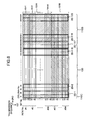
- (Kr ⁇ Nc) bytes of the entire Kr C1-encoded subblocks 10-i are formatted into a second coded information block whose number of parallel stages is increased from Kr to Nr to create an empty area of ⁇ (Nr-Kr) ⁇ Nc ⁇ bytes.
- an area 120A indicated by blank corresponds to the second coded information block
- an area 120B indicated by rightwardly inclined hatchings corresponds to the empty area.
- Nr is an arbitrary integer value larger than Kr, for example, 18.
- the resultant signal is segmented into arbitrary m columns, i.e., every (Nr ⁇ m) bytes.
- a check bit calculation for the C2-encoding is performed on a total of (Kr ⁇ m) bytes from the first to Kr-th rows in the area 120A, and resulting check bits are placed in a total of ⁇ (Nr-Kr) ⁇ m ⁇ bytes from the (Kr+1)th to Nr-th rows in the area 120B, where jm represents ⁇ Nc/m>, and ⁇ z> represents a minimum integer value equal to or larger than z.
- the check bits of the code subblock 20-j may be shifted and placed in a check bit area for the next code subblock 20-(j+1), in which case a delay time possibly caused by the encoding can be limited.
- the check bits of the last code subblock 20-jm are placed in a check bit area for a code subblock 20-1 of the next frame.
- the code subblock 20-jm may be excluded from those subjected to the C2-encoding, or the code subblock 20-jm may be C2-encoded together with the next second coded information block without interruption.
- appropriate encoding/decoding can be realized by inserting a particular framing pattern as described later in a method of using the first column.
- a ⁇ -error-correcting RS code (nd, kd) or a ⁇ -error-correcting BCH code (ne, ke) may be used.
- Nr is 256
- Np is 2 r
- one bit must be excluded from a code region
- a region except for that required for the check bits in the area 120B may be used as an information region for encoding or set to a virtual fixed value.
- a C2 code has the above nd less than 255 or ne less than ((2 r )-1), it is regarded as a shortened code in which logically lacking information is virtually assumed to be zero.
- (Nr ⁇ Nc) bytes of a coded block 130 which has undergone the C1-encoding and the C2-encoding as described above, is interleaved in Nr stages every ⁇ bytes from a row to another in the order reverse to the order in which the first coded information block was initially expanded in parallel, to convert the coded block 130 to a digital signal which has serially arranged bits on a time series basis. After the resulting digital signal is scrambled as required, it is transmitted to the super line side as a super FEC signal.
- the interleaving is performed in a sequence such that ⁇ consecutive bytes on the first row in Fig.
- ⁇ consecutive bytes on the serial digital signal are mapped to ⁇ consecutive bytes on the serial digital signal
- ⁇ consecutive bytes on the second row are mapped to the next ⁇ consecutive bytes on the serial digital signal
- the value of ⁇ may be arbitrary as long as it is a divisor of Nc, for example, it may be one, identical to ⁇ , or the number of bytes for the interleaving in the multiplexing rule when the client signal is a SONET/SDH signal.
- every ⁇ bits may be mapped instead of every ⁇ bytes.
- "every ⁇ bytes" may be replaced with "every ⁇ bits" in the aforementioned and following descriptions.
- Fig. 21 shows a relationship between sequences of serial bits and bytes of the parallel signal and those of a serialized super FEC signal.
- Nc* indicates a value derived by dividing Nc by ⁇ .
- Fig. 21 shows the relationship between sequences of bits and bytes of data when a super FEC signal is converted into a parallel signal, and vice versa.
- ⁇ consecutive bytes (#1-1) on the serial super FEC signal are mapped to ⁇ serial bytes (#1-1) on the first row of the parallel signal, and subsequently, every ⁇ consecutive bytes (#2-1, #3-1, ..., #Nr-1) on the super FEC signal are mapped to every ⁇ bytes (#2-1, #3-1, ..., #Nr-1) on the second through Nr-th rows of the parallel signal to arrange the consecutive (Nr ⁇ ) bytes on the super FEC signal in Nr parallel rows.
- subsequent consecutive (Nr ⁇ ) bytes on the super FEC signal are also arranged in Nr parallel rows.
- the respective columns are simultaneously transmitted in an apparatus of interest.
- the bit rate of the super FEC signal is ⁇ (Nr/Kr) ⁇ (Nc/Kc) times as high as the bit rate of the client signal.
- the scrambling may be performed as appropriate in parallel.
- the scrambling may be performed on a parallellized signal in Nr stages before it is interleaved.
- the bit rate may be increased at a time by a factor of ⁇ (Nr ⁇ Nc)/(Kr ⁇ Kc) ⁇ to correspond to the coded block 130 of (Nr ⁇ Nc) bytes long.
- the first coded information blocks of (Kr ⁇ Kc) bytes long may be interleaved Kr times on a byte-by-byte basis, and placed in a region comprised of (Kr rows ⁇ Kc columns), which corresponds to the coded block 130, to create empty areas 110B, 110C, 120B.
- a framing pattern, and overhead for OAM&P (Operation, Administration, Maintenance and Provisioning) of a transmission network are inserted for establishing synchronization on the reception side.
- OAM&P Operaation, Administration, Maintenance and Provisioning
- the framing pattern is inserted into a portion or the entirety of the first column, and the overhead for OAM&P of the transmission network is inserted into the remaining area.
- the overhead for OAM&P may not be essentially inserted.
- the same value (F6) hex as the A1 byte defined in SONET or SDH is inserted into a framing area F1 of ix bytes long from the first to ix-th rows
- the same value (28) hex as the A2 byte defined in SONET or SDH is inserted into a framing area F2 of (iy-ix) bytes long from (ix+1)th to iy-th rows.
- (z) hex represents a value in hexadecimal notation.
- the framing pattern values may be other than the foregoing, and are preferably pattern values which have the least possible repetitions of the same values.
- a plurality (p) of second coded information blocks or a plurality (p) of coded blocks may be chosen to be a single multiframe, wherein a previously determined framing pattern may be inserted into an area assigned to the top second coded information block in the single multiframe or a portion or the entirety of the first column in the plurality of encoded blocks, while the overhead for OAM&P of a transmission line may be inserted into the remaining area and into the first column of each of second to p-th blocks.
- a framing pattern set A is inserted into the first column in the current second coded information block, and a framing pattern set B different from the framing pattern set A is inserted into the first column of each of the next second coded information block to a second coded information block in which a certain code subblock 20-jp (1 ⁇ jp ⁇ jm) ends exactly on the Nr-th column.
- the decoding side can detect a second coded information block in which a code subblock 20-1 begins from the first column by finding the framing pattern set A, so that an appropriate decoding operation can be realized by beginning an decoding operation at the time this block position is first detected.
- a value (F6) hex may be inserted into the framing area F1
- a value (28) hex may be inserted into the framing area F2.
- a value (AA) hex may be inserted into the framing area F1
- a value (33) hex may be inserted into the framing area F2.
- the overhead for OAM&P of a transmission network may be inserted instead of the framing pattern set B.
- the scrambling is omitted in the areas in which the framing patterns are inserted.
- decoding side which receives and decodes a super FEC signal and then transmits the decoded signal to a communication path on the client side as a client signal.
- a signal is processed in the order reverse to the encoding side.
- a super FEC signal encoded as described above, is received through a transmission line from the super line side and frame-synchronization is established, the resulting signal is descrambled as required, and each of encoded blocks having (Nr ⁇ Nc) bytes is parallelly expanded (de-interleaved) in Nr stages every ⁇ bytes.
- the entire region in Fig. 2 corresponds to the coded blocks that have been parallelly expanded.
- the frame synchronization and descrambling may be performed adequately in parallel.
- the coded blocks may be parallelly expanded in Nr stages every ⁇ bytes at this stage.
- the de-interleaving is performed in a sequence such that ⁇ consecutive bytes on a serial super FEC signal are mapped to ⁇ serial bytes on the first row in Fig. 2, the next ⁇ consecutive bytes on the super FEC signal are mapped to ⁇ serial bytes on the second row, and so on, as shown in Fig. 21.
- C2 codes are decoded in the order in which these code blocks have been received (called the "C2 decoding").
- the code subblocks 10-i are interleaved every ⁇ bytes from the first to Kr-th rows in Fig. 1 from one row to another in Kr stages to restore an original client signal which has its bits serially arranged in a time serial manner. If necessary, the restored client signal is converted into an optical signal which is then outputted to the transmission path on the client side.
- the interleaving is performed in a sequence such that ⁇ consecutive bytes on the first row in Fig. 1 are mapped to ⁇ consecutive bytes on the serial client signal, ⁇ consecutive bytes on the second row are mapped to the next ⁇ consecutive bytes on the serial client signal, and so on, as shown in Fig. 20.
- a BIP (Bit Interleaved Parity) parity may be added to the overhead for OAM&P, such that the performance can be monitored on the decoding side based on the number of error bits which can be detected by matching the BIP parity both or either of before decoding and after decoding.
- the performance may be monitored directly based on the number of error bits which were corrected in a decoder.
- the performance may be monitored using the result of a syndrome calculation associated with ⁇ to zero-th power in the decoder.
- This monitoring utilizes the fact that the syndrome calculation associated with ⁇ to zero-th power has a function equivalent to the BIP parity matching.
- ⁇ is a primitive element of Galois field (2 n ) which is the basis for the Reed-Solomon code and BCH code.
- threshold values may be set for the number of bit errors and the bit error ratio from an external control system, such that the actual number of bit errors and bit error ratio found by the foregoing performance monitoring method are compared with the thus set threshold values, respectively, and the external control system is notified of degradation alarm if any threshold value is exceeded.
- the method for encoding a generator polynomial for the RS code and BCH code, check bit calculating method, decoding algorithm, i.e., syndrome calculating method, method for calculating an error position and error value based on the syndrome, and method for compensating for code shortening are well known, so that detailed description thereon is omitted.
- the first embodiment can facilitate the encoding of an error correcting code which has a sufficient gain of 6 dB or more for a bit error ratio of 10 -12 .
- an error correcting code which is suitable for maintaining a transmission distance when the degree of multiplexing is increased in the time division multiplexing, maximizing the transmission distance for a mixture of optical signals at different bit rates in the wavelength division multiplexing, and increasing a regenerator interval on condition that the degree of multiplexing is not changed in the time division multiplexing.
- FIG. 3 and 4 A second embodiment of the method for encoding an error correcting code according to the present invention is shown in Figs. 3 and 4.
- Figs. 3 and 4 each show an area for coded data in a frame structure.
- a client signal is parallellized to 16 bytes on a byte-by-byte basis.
- Each of the parallellized 16 bytes corresponds to 16 rows.
- each byte is parallellized on a bit-by-bit basis, so that the client signal is parallellized to 128 row in consequence.
- code subblocks 10-i for the C1-encoding comprise 16 subblocks each having a length of 255 bytes corresponding to each of 16 rows, either of the following two can be employed as the C1 code:
- the code subblocks 10-i for the C1-encoding comprise 128 subblocks each having a length of 255 bits corresponding to 128 parallellized bits, the following may be employed as the C1 code:
- the bite rate of a super FEC signal in the second embodiment is approximately 1.2054 times as high as that of a client signal.
- the second embodiment can facilitate the encoding of an error correcting code which has a sufficient gain of 8 dB for a bit error ratio of 10 -12 .
- an error correcting code which is suitable for maintaining a transmission distance when the degree of multiplexing is increased in the time division multiplexing, maximizing the transmission distance for mixed optical signals at different bit rates in the wavelength division multiplexing, and increasing a regenerator interval on condition that the degree of multiplexing is not changed in the time division multiplexing.
- FIG. 5 and 6 Another embodiment of the method for encoding an error correcting code according to the present invention is shown in Figs. 5 and 6.
- Figs. 5 and 6 each show an area for coded data in a frame structure.
- a client signal is parallellized to 56 bytes on a byte-by-byte basis.
- Each of the parallellized 56 bytes corresponds to 56 rows.
- each byte is parallellized on a bit-by-bit basis, so that the client signal is parallellized to 448 bits as a consequence.
- code subblocks 10-i for C1-encoding comprise 56 subblocks each having a length of 256 bytes corresponding to each of 56 rows, either of the following two may be employed as the C1 code:
- code subblocks 10-i for the C1 coding comprise 448 subblocks each having 256 bits corresponding to 448 parallellized bits
- the following may be employed as the C1 code:
- the bite rate of a super FEC signal in the third embodiment is approximately 1.2611 times as high as that of a client signal.
- the third embodiment can further facilitate the encoding of an error correcting code having a higher gain than the second embodiment.
- a predetermined check bit area may be created by increasing only the number of columns while maintaining the number of rows Kr constant.
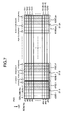
- Fig. 7 shows another embodiment of the method for encoding an error correcting code according to the present invention.
- Fig. 7 shows an area for coded data in a form structure.
- the fourth embodiment implements C2-encoding/ decoding shown in Fig. 7, premised on the C1-encoding/ decoding previously described in the first embodiment in connection with Fig. 1, and differs from the first embodiment in that a check bit area for a C2 code is defined at a position different from that shown in Fig. 2 (of the first embodiment). The following description will be centered on this difference.
- (Nr-Kr) rows which were created by increasing the number of parallel stages upon the C2-encoding, are used as the check bit area 120B for the C2 code.
- jm is equal to (Nc/m).
- bit rate of the super FEC signal is increased to ⁇ (Nr/Kr) ⁇ (Nc/Kc) ⁇ times as high as the bit rate of a client signal, thus providing the same result as the first embodiment.
- the check bits for the C2 code can be positioned at the end of the C2 code in the transmission sequence, in other words, in the reception sequence, thereby making it possible to simplify a scheme for parallelly processing the encoding/decoding of the C2 code, and suppress a delay time possibly occurring due to the encoding.
- Fig. 8 shows another embodiment of the method for encoding an error correcting code according to the present invention.
- Fig. 8 shows an area for data to be encoded in a frame structure.
- the fifth embodiment is generally similar to the preceding fourth embodiment except that the fifth embodiment employs a more general approach including the fourth embodiment. The following description will be centered on this respect.
- a total of (Nc+jm ⁇ ) columns are created.
- the C2-encoding is performed independently for each of the code subblocks 21-j segmented as described above.
- bit rate of the super FEC signal is increased to ⁇ (1+( ⁇ /m) ⁇ (Nc/Kc) ⁇ times as high as the bit rate of a client signal.
- the check bits for the C2 code can be positioned at the end of the C2 code in the transmission sequence, thereby making it possible to simplify a scheme for parallelly processing the encoding/decoding of the C2 code, and more flexibly encode a code which can suppress a delay time possibly occurring due to the encoding.
- the transmission sequences shown in Figs. 1 through 8 indicate a sequence in which information is transmitted on a client signal and a sequence in which information is transmitted on a super FEC signal.
- a transmission sequence as a parallellized signal is a "second direction of the transmission sequence" indicated in each figure.
- the respective rows are simultaneously transmitted for processing.
- the columns may be processed in accordance with a further parallellization scheme, for example, in (Kr ⁇ four stages), (Kr ⁇ 16 stages) or the like.
- the respective columns may be transmitted in a "first direction of the transmission sequence" indicated in each figure for simultaneous processing.
- a predetermined area in the check bit area 120B for the C2 code may be used as a second overhead area, in addition to the area 110C, for inserting a portion or the entirety of the framing pattern and the information for OAM&P of a transmission line into this additional area.
- the client signal When a client signal is received and converted into a super FEC signal, the client signal is reframed for C1-encoding, without increasing the bit rate by a factor of (Nc/Kc) for creating a check bit area for a C1 code, followed by a transition to the C2-encoding process which specifically involves an increase in the bit rate for C2 codes, the C2-encoding, and the insertion of overhead.
- This scheme is called "single stage wrapper.”
- the reframing of a client signal means that a framing pattern of the client signal is detected to arrange the client signal as shown in Fig. 1, and information in an overhead area 110C of the client signal is terminated to insert again new information as required.
- the client signal when a client signal has been encoded with the same code as the C1 code, the client signal may be once C1-decoded for the existing C1 code and subsequently C1-encoded again (method 1); the client signal may be newly C1-encoded ignoring the existing C1 code (method 2); or the client signal may be once C1-decoded for the existing C1 code and left as it is (method 3), followed by a transition to the C2-encoding process, respectively.
- double stages wrapper may be employed, wherein the bit rate of the client signal is increased and C1-encoded, followed by a transition to the C2-encoding process in the same method as the foregoing embodiments, without taking into account the frame format of the client signal (method 4).
- the overhead area 110C may be processed in a transparent manner without using as an overhead area, and a predetermined area in the bit check area 120B for the C2 code may be used as a second overhead area.
- the super FEC signal when a super FEC signal is received and converted into a client signal, and either of the methods 1 - 3 has been used on the encoding side, the super FEC signal may be once C1-decoded for a C1 code and again C1-encoded (method 1B) after a C2 decoding process; the super FEC signal may be newly C1-encoded again without C1 decoding (method 2B); or the super FEC signal may be once C1-decoded and left as it is (method 3B). Then, the resulting signal may be outputted as the client signal without reducing the bit rate by a factor of (Kc/Nc) in either of the methods.
- the super FEC signal may be C2-decoded and C1-decoded using the same method as the foregoing embodiments, and outputted as the client signal after its bit rate is reduced (method 4B).
- the method 1B - 3B may be performed on the decoding side.
- a selection as to which of these methods 1 - 4 should be performed may be made on the encoding side based on settings from an external control system.
- a selection as to which of these methods 1B - 4B should be performed may be made on the decoding side based on settings from an external control system, or automatically.
- an arbitrary predetermined area in the overhead for OAM&P within the first column for example, may be defined as an FSI byte into which a predetermined code value is inserted corresponding to an operation instruction for the decoding on the encoding side.
- the code value in the FSI byte is detected to select any of the methods 1B - 4B corresponding to the detected code value, and the selected method is performed.
- a similar selection may be made as to the insertion of a code value corresponding to which operation instruction into the FSI byte on the encoding side based on settings from the external control system.
- the sixth embodiment it is possible to encode a high gain code to generate a super FEC signal while ensuring the mutual connectivity when a client signal has been C1-encoded.
- the C1-encoding and the C2-encoding may be performed in the reverse order on the encoding side, while the C1-decoding and the C2-decoding may be preformed in the reverse order on the decoding side.
- jmb is equal to ⁇ Kc/m>.
- the two increases in the bit rate by a factor of (Nx/Kc) and by a factor of (Nr/Kr) or ⁇ 1+( ⁇ /m) ⁇ may be initially performed in succession.
- the bit rate of serial data of a received client signal before parallel expansion, or the bit rate after the parallel expansion is increased by a factor of ⁇ (Nc/Kc) ⁇ (Nr/Kr) ⁇ and [(Nc/Kc) ⁇ ⁇ 1+( ⁇ /m) ⁇ ], respectively, and the first coded information block is relocated at a predetermined position.
- the check bit areas 120B and 120C for the C2 codes may be left as they are, rather than eliminating them after the C2 decoding, such that the C2 decoding is performed again after the C1 decoding has been performed ignoring the check bit areas 120B, 120C for the C2 codes. Further, the C1 decoding may be performed again after this, or subsequently, the C2 decoding and the C1 decoding may be alternately repeated in sequence.
- the bit rate may be eventually reduced by a factor of ⁇ (Kr/Nr) ⁇ (Kc/Nc) ⁇ such that an original client signal can be restored.
- the bit rate may be reduced by a factor of (Kr/Nr) and by a factor of (Kc/Nc) in each process such that an original client signal can be restored.
- the C2 decoding and the C1 decoding are alternately repeated in sequence, so that a higher gain can be provided than the case where the C2 decoding and the C1 decoding are each performed only once.
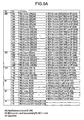
- Fig. 9A shows examples of possible C1 codes which can be applied to a combination of Kc, Nc, and Fig. 9B shows examples of possible C2 codes which can be applied to a combination of Kr, Nr, m, ⁇ .
- a code having a shorter code length for example, in a range of 127 to 144 bits/bytes
- a simple decoding algorithm for example, a one- to three-error-correcting RS/BCH code is employed as the C2 code at the cost of a lower correcting capability, it is possible to reduce a delay time associated with the encoding and decoding and simplify the scheme of encoding/decoding.
- the most efficient code can be provided by limiting the increase in the bit rate in a range of 110 % to 130% for encoding.
- the ratio of the super FEC signal to the client signal in bit rate, when expressed in percentage may be determined in a range of 110 % to 130 %, and the C1-encoding and the C2-encoding are performed such that check bits can be accommodated in such a redundancy bit area or empty area.
- Fig. 10 shows another embodiment of the method for encoding an error correcting code according to the present invention.
- the ninth embodiment differs from the aforementioned embodiments in that the sequence of columns is exchanged before encoded code subblocks are interleaved in Nr stages, after the C2-encoding has been performed as described in the first through fifth embodiments. The following description will be centered on this difference.
- the second columns 20-j-2 in the respective code subblocks 20-j are arranged in order likewise from the subblock having the smallest value of j to create a total of (2 ⁇ jm) columns.
- the third columns 20-j-3 through the m-th columns 20-jm in the respective code subblocks 20-j are similarly manipulated to create a total of (m ⁇ jm) columns.
- the signal relocated in this way is used as the coded blocks which is then interleaved in Nr stages every ⁇ bytes from a row to another, in a manner similar to the first through fifth embodiments, to generate a super FEC signal.
- the ninth embodiment may be applied to the fourth embodiment. Also, when the above Nr is replaced with Kr, and m with (m+ ⁇ ), the ninth embodiment may also be applied to the fifth embodiment.
- the ninth embodiment may be applied to the sixth and seventh embodiments.
- the ninth embodiment may also be applied to single encoding with the C1 code.
- the bit rate may be further increased to perform the C1-encoding and the C2-encoding as in the aforementioned embodiments, or the rearrangement may be repeated a plurality of times to generate a super FEC signal.
- the operation reverse to that on the encoding side i.e., a sequence of reverse arrangement ⁇ C2 decoding ⁇ C1 decoding ⁇ bit rate reduction are repeated the same number of times as the encoding side.
- the C2-encoding is performed before the sequence of the columns is changed
- the sequence of the columns may be changed immediately after the C1-encoding is performed and subsequently the C2-encoding may be preformed.
- the rearrangement similar to the foregoing may be performed after the above Nr is replaced with Kr, and jm with a proper value equal to or more than two.
- the ninth embodiment even if the super FEC signal suffers a large burst of errors, the errors are distributed to different C1 code areas and different C2 code areas by the reverse arrangement on the decoding side, so that the super FEC signal can have a high error correcting capability.
- Fig. 11 shows another embodiment of the error correcting code according to the present invention.
- the tenth embodiment differs from the foregoing embodiments in that, after performing the C2-encoding described in the first through third embodiments, respective rows are slightly moved in a forward or backward direction before code subblocks are interleaved in Nr stages. The following description will be centered on this difference.
- a second row (designated 130-1-2 in Fig. 11) is shifted temporally backwardly by jd bytes and located at the shifted position, where jd is an arbitrary integer value equal to or more than one.
- a third row (designated 130-1-3 in Fig. 11) is shifted temporally backwardly by (2 ⁇ jd) bytes and located at the shifted position.
- Similar manipulations are performed for third through Nr-th rows, with the result that an Nr-th row (designated 130-1-Nr in Fig. 11) is located at a position shifted temporally backwardly by (Nr ⁇ jd) bytes.
- the first column in the coded block 130 is excluded from the rearrangement such that the framing pattern can be readily detected on the decoding side.
- the first column may also be rearranged as the case may be.
- the signal rearranged in the manner described above is interleaved in NR stages every ⁇ bytes from a row to another in a manner similar to the first through third embodiments, to generate a super FEC signal.
- a reverse arrangement is performed to restore the original sequence of the rows, followed by the C2 decoding and the C1 decoding.
- the tenth embodiment can also be applied to the fourth and fifth embodiments when the above Nr is replaced with Kr.
- the tenth embodiment can further be applied to the single encoding with the C1 code when the above Nr is replaced with Kr, and the rearrangement similar to the foregoing is performed after the C1-encoding.
- the bit rate may be further increased to perform the C1-encoding and the C2-encoding as in the aforementioned embodiments, or the rearrangement may be repeated a plurality of times to generate a super FEC signal.
- the operation reverse to that on the encoding side i.e., a sequence of reverse arrangement ⁇ C2 decoding ⁇ C1 decoding ⁇ bit rate reduction are repeated the same number of times as the encoding side.
- the positions of the respective rows are shifted after the C2-encoding has been performed, the positions of the respective rows may be shifted immediately after the C1-encoding is performed and subsequently the C2-encoding may be preformed.
- the rearrangement may be performed in a manner similar to the foregoing after the above Nr is replaced with Kr and the C1-encoding is performed.
- the super FEC signal even if the super FEC signal suffers a large burst of errors, the errors are distributed to different C1 code areas and different C2 code areas by the reverse arrangement on the decoding side, so that the super FEC signal can have a high error correcting capability.
- the framing pattern area and the overhead area for OAM&P of a transmission network in the super FEC signal may be excluded from data subjected to the C1-encoding and the C2-encoding.
- the first column may be encoded as virtually regarded as (00) hex on the encoding side, while the first column may be decoded as regarded virtually as (00) hex likewise on the decoding side.
- an external control system may be used to control whether or not these areas are excluded.
- the encoding/decoding may be performed by selecting whether values in the first column are used as they are or they are virtually regarded as (00) hex when "excluded"/"not excluded” is set. Further, in each of the C1 decoding and the C2 decoding on the decoding side, settings from the external control system may be relied on to determine whether or not the first column should be excluded from a C1 code area and a C2 code area, or such a determination may be automatically performed.
- an arbitrary predetermined area of the overhead for OAM&P in the first column is defined as an FSIB byte, and a predetermined code value corresponding to the determination as to whether or not the first column is encoded is inserted into the FSIB byte on the encoding side.
- the code value in the FSIB byte is detected to perform an operation corresponding to the detected code value.
- the FSIB byte may be the aforementioned FSI byte.
- the foregoing settings and automatic operation may be performed independently on the framing pattern area and the overhead area for OAM&P of a transmission network.
- the overhead area for OAM&P may be divided into a plurality of areas such that the foregoing settings and automatic operation are performed independently on the respective divided areas.
- the foregoing settings and automatic operation may be performed independently on the C1 code and the C2 code, respectively.
- the eleventh embodiment it is possible to independently set whether or not the framing pattern area and the overhead area for OAM&P should be encoded for each of the C1 code and the C2 code, to make OAM&P of a transmission network more flexible and easier, and to automatically perform OAM&P of the transmission network without intervention of the operator.
- the decoding operation may be automatically turned ON and OFF.
- an arbitrary predetermined area of the overhead for OAM&P in the first column is defined as an FSIC byte, and a predetermined code value corresponding to a determination as to whether or not the encoding is performed is inserted into the FSIC byte on the encoding side.
- the code value in the FSIC byte is detected to turn the decoding operation ON when the code value indicates that the encoding has been performed, and to turn the decoding operation OFF when the code value indicates that the encoding has not been performed.
- the FSIC byte may be the aforementioned FSI byte or FSIB byte.
- a predetermined code value corresponding to the encoded case may be inserted into the FSIC byte which belongs to a block that is temporally previous to the first encoded block, from which the encoding is actually started, or the second encoded block.
- an operation corresponding to a detected code value may be performed only when the same code value is detected in the FSIC byte temporally continuously M times.
- the insertion of a code value into the FSIC byte and automatic decoding may be independently performed on the C1 code and the C2 code, respectively, in the manner described above.
- the twelfth embodiment it is possible to automatically decode the C1 code and the C2 code independently of each other, to make OAM&P of a transmission network more flexible and easier, and to automatically perform OAM&P of the transmission network without intervention of the operator.
- the client signal may be any of the following signals. Additionally, other than the following signals, the client signal may be an arbitrary binary digital signal which has a temporally constant bit rate, or an optical signal converted from such a binary digital signal.
- bit rate per bit is 77.76 Mbit/s (Mega Bits Per Second).
- bit rate per bit is 38,88 Mbit/s; and when Kr is chosen to be 16, the bit rate per bit is 19.44 Mbit/s.
- an OC-192 signal having a bit rate of 9.95328 Gbit/s or an STM-64 signal used as a client signal when the number of stages Kr in the parallel expansion is chosen to be 16, and all bits in each bytes are parallelly expanded, a total of 128 bits of parallel expansion is provided, and the bit rate per bit is 77.76 Mbit/s.
- the bit rate per bit when Kr is chosen to be 32, the bit rate per bit is 38,88 Mbit/s; and when Kr is chosen to be 64, the bit rate per bit is 19.44 Mbit/s.
- the bit rate per bit may be varied in accordance with the bit rate of a client signal, such that the bit rate per bit of a parallel signal is set to 77.76 Mbit/s when the client signal is an OC-192 signal or an STM-64 signal; the bit rate per bit is set to 19.44 Mbit/s when the client signal is an OC-48 signal or an STM-16 signal; and the bit rate per bit is set to 4.86 Mbit/s when the client signal is an OC-12 signal or an STM-4 signal.
- the bit rate may be maintained unchanged while the 8B10B code is terminated.
- the termination of the 8B10B code means restoration of data before it is 8B10B encoded.
- the amount of data is reduced to 80 %, so that the remaining 20 % of capacity, i.e., 25 % of capacity for the amount of data after the termination of the 8B10B code, is provided as an empty area which can be freely used.
- a capacity of 0.25 Gbit/s is provided as an empty area which can be freely used.
- an idle pattern previous to the end of the 8B10B code may be removed and a proper delimiter pattern may be inserted instead so as to clearly find the boundary between adjacent packets.
- the idle pattern previous to the end of the 8B10B code may be converted into a proper pattern for identification such that the capacity is reduced to Y % (Y ⁇ 100) after the termination of the 8B10B code.
- each 8-bit data may be converted into 9-bit data by a predetermined method after the termination of the 8B10B code to reduce the bit rate to 90 %.
- a bit having the value "0" may be added to the head of each 8-bit data in packets to increase the number of bits to a total of nine bits, while an arbitrary 9-bit section having the first bit having the value "1" and the subsequent eight bits arranged in a predetermined pattern may be used as a delimiter pattern which may be placed between packets.
- this area may be used as a check bit area for the C1 code, and as a check bit area for the C2 code to perform the C1-encoding in the aforementioned embodiments, and further the C2-encoding as well. Then, the 8B10B code may be restored upon reproducing the client signal on the decoding side. In this way, the super FEC signal can be encoded without increasing the bit rate.
- any of the foregoing embodiments employs a pseudo product code or concatenated code using the C1 code as an outer code and the C2 code as an inner code
- the encoding may be performed only with a single code.
- a client signal is converted into the frame structure shown in Fig. 1, in a manner similar to the foregoing embodiments, and then is subjected to the C1-encoding.
- the C1-encoded data is interleaved in Kr stages every ⁇ bytes as it is to generate a super FEC signal.
- the operation reverse to the above is performed to restore the client signal.
- ⁇ related to the parallellization of a client signal having a bit rate ( ⁇ ) Gbit/s is set to one; Kr to 16 to parallellize all bits in each byte to a total of 128 parallel signals; Kc to 238; Nc to 255; C1 to an eight-error-correcting Reed-Solomon code (255, 239); and the encoding processing speed for each of the total of the 128 parallel signals to ⁇ ( ⁇ /128) ⁇ 1000 ⁇ Mbit/s before increasing the bit rate, and to ⁇ /128) ⁇ (255/238) ⁇ 1000 ⁇ Mbit/s after increasing the bit rate.
- the processing speed for the decoding is set in a similar manner.
- the processing speed for each parallel signal is set to 77.76 Mbit/s before increasing the bit rate, and to approximately 83.4 Mbit/s after increasing the bit rate.
- the processing speed for each parallel signal is set to 97.65625 Mbit/s before increasing the bit rate, and to approximately 104.7 Mbit/s after increasing the bit rate.
- the processing speed for each parallel signal is set to 155.52 Mbit/s before increasing the bit rate, and to approximately 166.7 Mbit/s after increasing the bit rate. Further, for a client signal having a bit rate of 39.81312 Gbit/s, the processing speed for each parallel signal is set to 311.04 Mbit/s before increasing the bit rate, and to approximately 333.3 Mbit/s after increasing the bit rate.
- each of 16 parallel signal sets, each comprised of eight parallel signals is independently encoded and decoded, so that apparatus involved in the encoding/decoding have a constant scale suitable for 16 sets, irrespective of the bit rate of any client signal.
- the client signal is parallellized in a manner similar to the foregoing, whereas for a signal having a bit rate equal to an integer multiple of the bit rate of these signals, the number of parallellized signals may be increased by a factor of the integer multiple ( ⁇ ).
- Kr is set to 16, and all bits in each byte are parallellized to generate a total of 128 parallellized bits in the manner described above, whereas for a signal having a bit rate of ( ⁇ 9.95328) Gbit/s, Kr is set to ( ⁇ 16), and all bits in each byte are parallellized to generate a total of ( ⁇ 128) parallellized bits.
- the processing speed for each parallel signal is fixed to 77.76 Mbit/s before increasing the bit rate, and to approximately 83.4 Mbit/s after increasing the bit rate, thereby making it possible to conform to the operating speed of LSIs fabricated by a silicon process and to limit an increase in the scale of apparatus involved in the encoding/decoding.
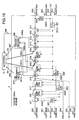
- Fig. 12 illustrates a super FEC signal transmitter according to a thirteenth embodiment of the present invention.
- Fig. 12 is a block diagram of the super FEC signal transmitter 2.
- the super FEC signal transmitter 2 receives a client signal 200, and outputs it as a super FEC signal 250.
- a clock extraction unit 210 restores from the received client signal 200 a clock signal 210C at the same bit rate as that of the client signal 200.
- a clock divider unit 211 divides the clock signal 210C from the clock extraction unit 210 to a processing rate at a first stage in the super FEC signal transmitter 2, for example, at a frequency 1/Kr times or 1/(8 ⁇ Kr) times as high as the original clock signal, and outputs the divided clock signal as a clock signal 211C.
- the super FEC signal transmitter 2 may receive a clock signal at a predetermined frequency from the outside as required, and synchronize this clock signal to the clock signal extracted in the clock extraction unit 210, using a PLL (Phase Locked Lop) circuit or the like. The resulting signal may be used as the clock signal 211C.
- PLL Phase Locked Lop
- a serial/parallel conversion unit 212 parallellizes the received client signal 200 in Kr stages every ⁇ bytes such that the period and phase of one bit thereof are equal to those of the clock signal 211C, and outputs the parallellized client signal.
- a first clock rate conversion unit 213 increases the frequency of the clock signal 211C from the clock divider unit 211 by a factor of (Nc/Kc), and outputs the resulting clock signal as a first clock signal 213C.
- a first frame conversion unit 214 increases the bit rate of each of parallel data signals from the serial/parallel conversion unit 212 by a factor of (Nc/Kc) using the timing of the first clock signal 213C from the first clock rate conversion unit 213, places the original parallel data signals in the area 100 within the frame format as shown in Figs. 1, 3, 5, and outputs the signals.
- An overhead processor unit 215 generates overhead information for OAM&P of a transmission network, framing pattern and so on, which are to be inserted into a super FEC signal for transmission, and outputs a portion or the entirety of a variety of the information 215a, 215b, 215c to a first overhead insertion unit 216, a second overhead insertion unit 218 and a third overhead insertion unit 222, respectively, for processing therein.
- the first overhead insertion unit 216 inserts a variety of information 215a from the overhead processor unit 215 into predetermined positions within a data signal from the first frame conversion unit 214, for example, predetermined positions in the area 110C shown in Figs. 1, 3, 5, and outputs the data signal having the information 215a inserted therein.
- a first encode processor unit 217 performs the Cl-encoding described in the aforementioned embodiments on the output data signal from the first overhead insertion unit 216.
- the second overhead insertion unit 218 inserts a variety of information 215b from the overhead processor unit 215 into predetermined positions previously defined in the data signal from the first encode processor unit 217, for example, predetermined positions in the area 110C shown in Figs. 1, 3, 5, and outputs the data signal having the information 215b inserted therein.
- a second clock rate conversion unit 219 increases the frequency of the first clock signal 213C from the first clock rate conversion unit 213 by a factor of (Nr/Kr) or ⁇ 1+( ⁇ /m) ⁇ , and outputs the resulting clock signal as a second clock signal 219C.
- a second frame conversion unit 220 increases the bit rate of each of the parallellized data signals from the second overhead insertion unit 218 by a factor of (Nr/Kr) or ⁇ 1+( ⁇ /m) ⁇ using the timing of the second clock signal 219C from the second clock rate conversion unit 219, places the original parallel data signals in the area 100B within the frame format as shown in Fig. 7 or 8, and outputs the signals. This is designated the "case 1.”
- the second frame conversion unit 220 creates (Nr-Kr) stages of parallel areas for the data signals from the second overhead insertion unit 218, places the original parallel data signals in the area 100 within the frame format as shown in Figs. 2, 4, 6, and outputs the parallel data signals in the frame format. This is designated the "case 2.”
- a second encode processor unit 221 performs the C2-encoding described in the aforementioned embodiments on the output data signal from the second frame conversion unit 220.
- the second encode processor unit 221 processes each of the code subblocks 20-j which remain parallelly expanded in Kr stages or Nr stages.
- parallelly inputted Kr bytes or Nr bytes may be subjected to a division/residue calculation using a generator polynomial, after performing a carry operation in accordance with the position of each byte or bit in the parallel arrangement.
- a delay time associated with the encoding can be reduced by using a code of a short length which has a small m as the C2 code.
- a third overhead insertion unit 222 inserts a variety of information 215c from the overhead processor unit 215 into predetermined positions in the data signal from the second encode processor unit 221, for example, predetermined positions in the area 110C shown in Figs. 1, 3, 5, and outputs the data signal having the information 215c inserted therein.
- a clock multiplier unit 223 multiplies the frequency of the second clock signal 219C from the second clock rate conversion unit 219 by an integer multiple, for example, by Kr or (8 ⁇ Kr) when the second frame conversion unit 220 is in the case 1 and by Nr or (8 ⁇ Nr) when in the case 2, and outputs the resulting clock signal as a third clock signal 223C.
- a clock signal at a predetermined frequency may be received from the outside as required, and used as the third clock signal 223C.
- a scrambler 224 randomizes the data signal and outputs the randomized data signal so as to prevent the same bit values from being transmitted successively.
- the scrambler 224 performs parallel processing so as to provide the same result as that produced when a serial data signal from the next parallel/serial conversion unit 225 is scrambled using a primitive polynomial of a predetermined order number as a generator polynomial.
- the scrambler 224 may be located subsequent to the parallel/serial converter 225 and used as a 1-bit serial processing scrambler.
- the parallel/serial conversion unit 225 interleaves a parallel data signal in Kr stages or Nr stages from the scrambler 224 every ⁇ bytes such that the period and phase of its one bit are equal to those of the third clock signal 223C to serialize the sequence of the bits on a time series basis, and outputs the serialized signal as a super FEC signal 250.
- each component from the first overhead insertion unit 216 to the second overhead insertion unit 218 operates at the timing of the clock signal 213C.
- Each component from the second encode processor unit 221 to the scrambler 224 operates at the timing of the clock signal 219C.
- the super FEC signal transmitter 2 may be controlled from an external control system 9.
- the external control system 9 may control the overhead processor unit 215 through a control signal 9a to generate a portion or the entirety of the overhead information for OAM&P and the framing pattern, and to insert which of the overhead information and the framing pattern in the first overhead insertion unit 216, second overhead insertion unit 218 and third overhead insertion unit 222, respectively.
- the external control system 9 may control the first encode processor unit 217 and the second encode processor unit 221 through control signals 9b, 9c as to which of methods 1 - 4, previously described in the sixth embodiment, should be performed, or whether or not the framing pattern and the overhead area for OAM&P should be encoded, as described in the eleventh embodiment, or whether or not the C1-encoding and the C2-encoding should be performed, as described in the twelfth embodiment. Further, if a faulty state such as an interrupted signal is detected in the client signal 200, or if the super FEC signal transmitter 2 presents a faulty operation, the external control system 9 may be supplied with an alarm 299 notifying the fault.
- the thirteenth embodiment it is possible to readily configure a super FEC transmitter which realizes the encoding to an error correcting code that has a sufficient gain of 6 dB or more for a bit error ratio of 10 -12 by performing the C2-encoding on a client signal after it has undergone the C1-encoding to convert the client signal into a super FEC signal.
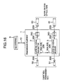
- Fig. 13 illustrates a super FEC signal transmitter according to another embodiment of the present invention.
- the super FEC signal transmitter 2 of the fourteenth embodiment is similar in configuration and operation to the thirteenth embodiment illustrated in Fig. 12, the former differs from the latter in that a first frame conversion unit 214 is located adjacent to a second frame conversion unit 220; a first clock rate conversion unit 213 is located adjacent to a second clock rate conversion unit 219; and a selector 227 and a selector 228 are added.
- the super FEC signal transmitter 2 of the fourteenth embodiment also differs in that it receives a parallel data signal 204 having a data format equivalent to a data format of the output signal of the second frame conversion unit 220; a clock signal 205 synchronized with the parallel data signal 204 and having the same frequency as the second clock signal 219C; and a phase pulse signal 206 indicative of the phase of the parallel data signal 204 from the outside.
- the first clock rate conversion unit 213, first frame conversion unit 214 and second clock rate conversion unit 219 are similar in operation to their counterparts in the thirteenth embodiment.
- the second frame conversion unit 220 performs similar processing to that in the thirteenth embodiment on a parallel data signal from the first frame conversion unit 214. Further, in the case 1, the first frame conversion unit 214 can be removed, in which case the bit rate of each parallel data signal from a serial/ parallel conversion unit 212 may be increased directly by a factor of ⁇ (Nr/Kr) ⁇ (Nc/Kc) ⁇ or [ ⁇ 1+( ⁇ /m) ⁇ (Nc/Kc) ⁇ ] using the timing of a second clock signal 219C from the second clock rate conversion unit 219, and the original parallel data signal may be placed in the area 100B within the frame format as shown in Fig. 7 or 8, and outputted.
- the selector 227 receives the parallel data signal from the second frame conversion unit 220 and the parallel data signal 204 received from the outside, selects either of these signals, and outputs the selected signal.
- the selector 228 receives the second clock signal 219C from the second clock rate conversion unit 219, and the clock signal 205 received from the outside, selects either of these clocks, and outputs the selected clock signal as a clock signal 228C.
- selector 227 and the selector 228 select signals in the same system. Specifically, when the selector 227 selects the parallel data signal from the second frame conversion unit 220, the selector 228 selects the second clock signal 219C. Conversely, when the selector 227 selects the parallel data signal 204, the selector 228 selects the clock signal 205.
- the external control system 9 may control through a control signal 9f the selections made by the selectors 227, 228.
- the selector 227 selects the parallel data signal 204
- the frame position of the parallel data signal 204 is recognized based on the phase pulse signal 206 received from the outside in each process subsequent to a first overhead insertion unit 216.
- the fourteenth embodiment is similar to the thirteenth embodiment except that the first overhead insertion unit 216 processes a data signal from the selector 227, and a second encode processor unit 221 processes a data signal from a second overhead insertion unit 218.
- the fourteenth embodiment it is possible to readily configure a super FEC transmitter which realizes the encoding to an error correcting code which has a sufficient gain for a bit error ratio of 10 -12 by performing the C1-encoding and C2-encoding on a client signal after its bit rate is increased to a predetermined bit rate to convert the client signal into a super FEC signal.
- the second clock rate conversion unit 219, second frame conversion unit 220, second encode processor unit 221 and third overhead insertion unit 222 may be removed in the configuration of Fig. 12 or 13 such that the previous and subsequent components are directly connected.
- first overhead insertion unit 216 may be removed in the configuration of Fig. 12 or 13 to make a direct connection.
- a predetermined framing pattern is inserted in either the first encode processor unit 217 or the second encode processor unit 221.
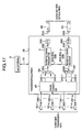
- Fig. 14 illustrates a super FEC signal receiver according to a fifteenth embodiment of the present invention.
- Fig. 14 is a block diagram of the super FEC signal receiver.
- the super FEC signal receiver 3 receives a super FEC signal 350, and outputs it as a client signal 300.
- a clock extraction unit 330 restores from the super FEC signal 350 a clock signal 330C having the same bit rate as the super FEC signal 350, and outputs the clock signal 330C.
- a clock divider unit 331 divides the frequency of the clock signal 330C extracted in the clock extraction unit 330, for example, to be 1/Pr or 1/(8 ⁇ Pr) of the original clock signal to generate a processing rate at the first stage in the super FEC signal receiver 3, and outputs the resulting clock signal as a clock signal 331C.
- the super FEC signal receiver 3 may receive a clock signal at a predetermined frequency from the outside as required, and synchronize this clock signal to the clock signal extracted in the clock extraction unit 330, using a PLL circuit or the like. The resulting signal may be outputted as the clock signal 331C.
- a first clock conversion unit 332 reduces the frequency of the clock signal 331C from the clock divider unit 331 by a factor of (Pr/Nr) or ⁇ m/(m+ ⁇ ) ⁇ , and outputs the resulting clock signal as a first clock signal 332C.
- a second clock rate conversion unit 333 reduces the frequency of the first clock signal 332C from the first clock rate conversion unit 332 by a factor of (Kr/Nc), and outputs the resulting clock signal as a second clock signal 333C.
- a clock multiplier 334 multiplies the frequency of the second clock signal 333C from the second clock rate conversion unit 333 by an integer, for example, by Kr or (8 ⁇ Kr), and outputs the resulting clock signal as a third clock signal 334C.
- a clock signal at a predetermined frequency may be received from the outside as required and used as the third clock signal 334C.
- a serial/parallel conversion unit 311 parallellizes the received super FEC signal 350 in Pr stages every ⁇ bytes such that the period and phase of one bit thereof are equal to those of the clock signal 331C, and outputs the parallellized super FEC signal.
- a frame synchronization unit 312 detects a predetermined framing pattern from the parallel data signal from the serial/parallel conversion unit 311, and rearranges the signal in a proper sequence to output a signal in the frame format shown in Figs. 2, 4, 6, 7.
- a descrambler 313 performs the reverse operation to that performed in the scrambler 224 in the super FEC signal transmitter 2 illustrated in Fig. 12, which is the source of the super FEC signal 350, on the parallel data signal from the frame synchronization unit 312, to restore the data before it was scrambled.
- a first overhead extraction unit 314 extracts information at predetermined positions previously defined in the data signal from the descrambler 313, for example, at predetermined positions in the area 110C shown in Figs. 2, 4, 6, 7, and then outputs the data signal as it is to a first decode processor unit 315 as well as outputs the extracted information 340a to an overhead processor unit 340.
- the first decode processor unit 315 performs the C2 decoding described in the aforementioned embodiments on the output data signal from the first overhead extraction unit 314, and outputs the decoded data signal to a second overhead extraction unit 316 as well as outputs a C2 decoding result 341a (the number of corrected bits, an estimated number of uncorrectable bits if uncorrectable errors were found, and the number of error corrected bits when errors were corrected) to a FEC performance monitor unit 341.
- ELP error locator polynomial
- EMP error locator polynomial
- EVP error evaluator polynomial
- the error position calculation is performed by substituting an element of Galois field corresponding to a symbol position for an RS code and to a bit position for a BCH code into an ELP polynomial to determine whether or not an error exists at the symbol position or the bit position by examining whether or not the substitution results in "zero.”
- an element of Galois field corresponding to a symbol position or a bit position is substituted into an EVP polynomial or an ELP differential polynomial, and if an error is found at the symbol position or the bit position, the error value is calculated.
- error position and error value are calculated independently corresponding to a parallel position of each byte or bit in the Kr byte or Nr byte. In this event, the calculation may be made with a carry operation performed in accordance with each parallel position.
- the calculations of polynomial coefficients and error values for ELP and EVP require a division of Galois field, i.e., multiplication by an inverse element.
- approaches for deriving an inverse element of Galois field there are an approach for searching for an element which derives "1" as a result of a multiplication with an element of predetermined Galois field (called the “search approach”); an approach for deriving an inverse element by creating an original adjoint matrix of predetermined Galois field and calculating a reverse matrix or an upper triangle matrix or a lower triangle matrix (called the “matrix approach”); an approach for deriving an inverse element by previously storing inverse elements corresponding to all elements of Galois field and reading information corresponding to a predetermined element of Galois field from the memory (called the "memory approach”); and an approach for previously inputting all elements of Galois field in a selector and configuring the selector such that the selector selects and outputs an inverse element corresponding to a predetermined element of Ga
- the calculation within the processor unit 315 may be performed at a higher speed, i.e., using a local clock which may be generated by multiplying the first clock signal 331C by a proper value.
- error positions and error values corresponding to a pattern of syndrome may be previously stored in a memory, such that the decoding may be performed directly by reading information in the memory corresponding to the result of a calculation of the syndrome.
- polynomial coefficients of ELP and EVP may be previously found as an equation which includes the syndrome as a variable, so that the calculation can be simplified.
- the C2 code is a BCH code
- the polynomial coefficient calculation and error value calculation for EVP are not required. Further, a delay time associated with the decoding can be reduced by using a code which has a short code length with a small m as the C2 code.
- a second overhead extraction unit 316 extracts information at predetermined positions previously defined in a data signal from the first decode processor unit 315, for example, at predetermined positions in the area 110C shown in Figs. 2, 4, 6, 7, and then outputs the data signal as it is to a first frame conversion unit 317 as well as outputs the extracted information 340b to the overhead processor unit 340.
- the first frame conversion unit 317 increases the bit rate of each parallellized data signal from the second overhead extraction unit 316 by a factor of (Kr/Nr) or ⁇ m/(m+ ⁇ ) ⁇ using the timing of the first clock signal 332C from the first clock rate conversion unit 332, and places the original parallel data signal in the area 100 within the frame format as shown in Figs. 1, 3, 5, and outputs the signal.
- the first frame conversion unit 317 deletes or terminates parallel signals corresponding to (Nr-Kr) stages, which form a check bit area for the C2 code of the data signal from the second overhead extraction unit 316, so as to prevent the parallel signal from propagating to respective processes subsequent thereto, and places the original parallel data signal in the area 100 within the frame format as shown in Figs. 1, 3, 5, and outputs the signal.
- a second decode processor unit 318 performs the C1 decoding described in the aforementioned embodiments on the output data signal from the first frame conversion unit 317, and outputs the decoded signal to a third overhead extraction unit 319 as well as outputs a C1 decoding result 341b (the number of corrected bits, an estimated number of uncorrectable bits if uncorrectable errors were found, and the number of error corrected bits when errors were corrected) to the FEC performance monitor unit 341.
- Each of the C1 decode modules 318-MDJ-i calculates a syndrome from input data, polynomial coefficients of ELP and EVP from the syndrome, and error positions and error values from the polynomial coefficients of ELP and EVP.
- the calculations of the polynomial coefficients of ELP and EVP from the syndrome may be shared by the respective C1 decode modules 318-MDJ-i.
- the calculations may be performed for the respective code subblocks 10-i in sequence such that after the polynomial coefficients of ELP and EVP have been calculated for a code subblock 10-1, the polynomial coefficients of ELP and EVP are calculated for a code subblock 10-2.
- the shared code subblocks may be divided by two into 10-1 - 10-is (is ⁇ Kr) and 10-(is+1) - 10-Kr, or divided by four.
- the calculations of polynomial coefficients and error values for ELP and EVP require a division of Galois field, i.e., multiplication by an inverse element, wherein the inverse element can be derived using any of the aforementioned search approach, matrix approach, memory approach and selector approach.
- the calculation within the processor unit 318 may be performed at a higher speed, i.e., using a local clock which may be generated by multiplying the second clock signal 332C by a proper value.
- error positions and error values corresponding to a pattern of syndrome may be previously stored in a memory, such that the decoding may be performed directly by reading information in the memory corresponding to the result of the calculation of the syndrome.
- the C1 code is a BCH code
- the polynomial coefficient calculation and error value calculation for EVP are not required.
- the third overhead extraction unit 319 extracts information at predetermined positions previously defined in the data signal from the second decode processor unit 318, for example, at predetermined positions in the area 110C shown in Figs. 1, 3, 5, and then outputs the data signal as it is to a second frame conversion unit 320 as well as outputs the extracted information 340c to the overhead processor unit 340.
- the second frame conversion unit 320 increases the bit rate of each parallellized data signal from the third overhead extraction unit 319 by a factor of (Kc/Nc) using the timing of the second clock signal 333C from the second clock rate conversion unit 333, and restores parallel data equivalent to that inputted to the first frame conversion unit 214 in the super FEC signal transmitter 2 illustrated in Fig. 12, which is the source of the super FEC signal 350.
- a parallel/serial conversion unit 321 interleaves a parallel data signal in Kr stages from the second frame conversion unit 320 every ⁇ bytes such that the period and phase of its one bit are equal to those of the third clock signal 334C to serialize the sequence of the bits, and outputs the serialized signal as a client signal 300.
- the outputted client signal 300 restores the client signal 200 received at the super FEC signal transmitter 2 illustrated in Fig. 12 which is the source of the super FEC signal 350.
- the overhead processor unit 340 edits the overhead information 340a, 340b, 340c for OAM&P of a transmission network received from the first overhead extraction unit 314, second overhead extraction unit 316 and third overhead extraction unit 319, respectively, determines from the information whether or not the super FEC signal 350 is normal, monitors the performance quality such as a bit error ratio and the number of bit errors of the super FEC signal 350 to determine whether or not the super FEC signal 350 is degraded, or monitors an operating state and a maintenance state of a transmission network to notify the external control system 9 of PM information 397.
- the FEC performance monitor unit 341 totalizes the respective decoding results from the C1 decoding result 341b and the C2 decoding result 341a received from the first decode processor unit 315 and the second decode processor unit 318, respectively, and notifies the external control system 9 of the respective decoding results and the total result as an FEC-PM result 398.
- each component from the frame synchronization unit 312 to the second overhead extraction unit 316 operates at the timing of the clock signal 331C.
- the second decode processor unit 318 and the third overhead extraction unit 319 operate at the timing of the clock signal 332C.
- the super FEC signal receiver 3 may be controlled from the external control system 9.
- the external control system 9 may control the first decode processor unit 315 and the second decode processor unit 318 to perform which of the methods 1B - 4B described in the sixth embodiment; to determine whether or not the framing pattern area and the overhead area for OAM&P should be decoded, as described in the eleventh embodiment; and to determine whether or not the C1 decoding and C2 decoding are performed, as described in the twelfth embodiment, through control signals 9d, 9e. Further, if a faulty state such as an interrupted signal is detected in the super FEC signal 350, or if the super FEC signal receiver 3 presents a faulty operation, the external control system 9 may be supplied with an alarm 399 notifying the fault.
- the fourteenth embodiment it is possible to readily configure a super FEC receiver which generates a sufficient gain of 6 dB or more for a bit error ratio of 10 -12 by performing C1-decoding on a super FEC signal after it has undergone C2-decoding to convert the super FEC signal into a client signal.
- Fig. 15 illustrates a super FEC signal receiver according to another embodiment of the present invention.
- the super FEC signal receiver 3 of the sixteenth embodiment is similar in configuration and operation to the fifteenth embodiment illustrated in Fig. 14, except that a first frame conversion unit 317 is located adjacent to a second frame conversion unit 320; a first clock rate conversion unit 332 is located adjacent to a second clock rate conversion unit 333. Further, the super FEC signal receiver 3 of the sixteenth embodiment differs in that one of parallel data signals 304 branched from a third overhead extraction unit 319, a clock signal synchronized to the parallel data signal 304, i.e., one of clock signals 305 from the clock divider unit 331, and a phase pulse signal 306 indicative of the phase of the parallel data signal 304 are outputted to the outside of the super FEC signal receiver 3.
- the first clock rate conversion unit 332, first frame conversion unit 317, and second clock rate conversion unit 333 are similar in operation to their counterparts in the fifteenth embodiment.
- the second frame conversion unit 320 performs similar processing to its counterpart in the fifteenth embodiment on each parallel data signal from the first frame conversion unit 317. Further, in the transmission source case 1, the first frame conversion unit 317 can be removed, in which case, the bit rate of each of parallel data signals from the third overhead extraction unit 319 is directly increased by a factor of ⁇ (Kr/Nr) ⁇ (Kc/Nc) ⁇ or ⁇ (m/(m+ ⁇ ) ⁇ (Kc/Nc) ⁇ using the timing of a second clock signal 333C from the second clock rate conversion unit 333 to restore parallel data equivalent to that inputted to the first frame conversion unit 214 in the super FEC signal transmitter 2 illustrated in Fig. 12, which is the source of a super FEC signal 350.
- the sixteenth embodiment is similar to the fifteenth embodiment only except that the second decode processor unit 318 processes a data signal from the second overhead extraction unit 316.
- the sixteenth embodiment it is possible to readily configure a super FEC receiver which generates a sufficient gain by reducing the bit rate of a super FEC signal to a predetermined bit rate after the super FEC signal has been C2-decoded and C1-decoded to convert the super FEC signal into a client signal.
- the first clock rate conversion unit 332, first frame conversion unit 317, first decode processor unit 315 and first overhead extraction unit 314 may be removed in the configuration of Fig. 14 or 15 such that the previous and subsequent components are directly connected.
- each of the first overhead extraction unit 314, second overhead extraction unit 316 and third overhead extraction unit 319 may be removed, corresponding to the first overhead insertion unit 216, second overhead insertion unit 218 and third overhead insertion unit 222 in the super FEC signal transmitter 2 in Fig. 12, which is the source of the super FEC signal 350, to simply make a direct connection.
- properly parallellized client signals 201, 301 may be used instead of the client signals 200, 300.
- clock signals 202, 302 which are synchronized with these signals 201, 301 and have a bit rate equal to the bit rate of these signals 201, 301, may be received and transmitted.
- the first frame conversion unit 214 and the second frame conversion unit 220 need not convert the bit rate, but only have to properly relocate data positions within the client signal 200 or the client signal 201.
- the first frame conversion area 214 and the second frame conversion area 220 are not required.
- the first frame conversion area 214 and the second frame conversion area 220 are not required.
- by inserting, separating and matching a predetermined diagnosis pattern at an arbitrary position in the areas 110B, 110C, 120B, 120C it is possible to perform diagnosis related to signal transmission and reception between the source transmitter of the client signal 200 and the super FEC signal transmitter 2, or between the destination apparatus of the client signal 300 and the super FEC signal receiver 3.
- periodic phase pulse signals 203, 303 may also be received and transmitted for indicating predetermined positions in the data formats of the client signals 200, 300 and the parallellized client signals 201, 301.
- the super FEC signals 250, 350 may be parallellized super FEC signals 251, 351 which have been properly parallellized. Also, together with the parallellized super FEC signals 251, 351, clock signals 252, 352 synchronized with these signals and having a bit rate equal to the bit rate of these signals, and periodic phase pulse signals 253, 353 indicative of predetermined positions in the data formats of the super FEC signals 250, 350 and the parallellized super FEC signals 251, 351 may be received and transmitted.
- the first encode processor unit 217 and the second encode processor unit 221, and the first decode processor unit 315 and the second decode processor unit 318 may be built in separate LSIs or FPGAs in which encoding/decoding logics are fixedly implemented, or in separate microprocessors which operate the respective logics implemented as software, respectively.
- the two types of units may be implemented in one and the same LSI/FPGA, or in the same CPU which is installed with both software programs associated the respective units and operates the programs in time division.
- Fig. 16 illustrates a transmitting apparatus according to an embodiment of the present invention which employs one of the super FEC signal transmitters and one of the super FEC signal receivers described in the foregoing embodiments.
- the transmitting apparatus 1 of the seventeenth embodiment comprises the super FEC signal transmitter 2 illustrated in Fig. 13 and the super FEC signal receiver 3 illustrated in Fig. 15.
- the super FEC signal transmitter 2 receives a client signal 200 from a transmission path 50 on the client side, converts the client signal 200 into a super FEC signal 250 which is outputted to an electro-optical conversion unit 260.
- the electro-optical conversion unit 260 converts the super FEC signal 250 from the super FEC signal transmitter 2 to an optical signal 259 which has a waveform equivalent to that of the super FEC signal 250, a predetermined wavelength, and an optical power density, and outputs the optical signal 259 to an optical fiber transmission path 60 on the super line side.
- An opto-electric conversion unit 360 receives an optical signal 359 from an optical fiber transmission path 61 on the super line side, converts the optical signal 359 to an electric signal having a waveform equivalent to that of the optical signal 359, and outputs the electric signal as a super FEC signal 350.
- the super FEC signal receiver 3 converts a received super FEC signal 350 to a client signal 300 which is outputted to a transmission path 51 on the client side, and outputs a parallel data signal 304 after C1 decoding and C2 decoding, a clock signal 305 and a phase pulse signal 306 to a super FEC signal transmitter 2. This operation is designated the "operation mode A.”
- operation mode B A different operation from the above, performed by the super FEC signal transmitter 2 in the following manner, is designated the "operation mode B.”
- the super FEC signal transmitter 2 converts a parallel data signal 204, a clock signal 205 and a phase pulse signal 206 (connected to 304, 305, 306, respectively) received from the super FEC signal receiver 3 again to a super FEC signal 250 which is outputted to the electro-optical conversion unit 260.
- This operation is defined as the operation mode B.
- the selection of the two types of operation mode may be made by fixed wiring on hardware or controlled by the external controller 9 through a monitor control line 19.
- a client signal 300 from the super FEC signal receiver 3 may be branched such that one of branched signals is looped back to the super FEC signal transmitter 2, in which case the transmitting apparatus is operated in the operation mode A.
- the super FEC signal transmitter 2 illustrated in Fig. 12 may be used instead of that illustrated in Fig. 13, and the super FEC signal receiver 3 illustrated in Fig. 14 may be used instead of that illustrated in Fig. 15.
- the transmitting apparatus operates only in the operation mode A.
- the transmitting apparatus which is capable of converting a client signal into a super FEC signal for transmission, or regenerating and transmitting a super FEC signal.
- Fig. 17 illustrates a transmitting apparatus according to another embodiment of the present invention which employs one of the super FEC signal transmitters and one of the super FEC signal receivers described in the aforementioned embodiments.
- the transmitting apparatus 1B according to the eighteenth embodiment differs from the seventeenth embodiment in that a first cross-connect switch 4A, a first multiplexing unit 5A, and a first demultiplexing unit 6A are added to the configuration of the seventeenth embodiment.
- the super FEC signal transmitter illustrated in Fig. 12 may be used instead of that illustrated in Fig. 13, and the super FEC signal receiver 3 illustrated in Fig. 14 may be used instead of that illustrated in Fig. 15.
- the transmitting apparatus which is capable of converting a plurality of subclient signals into a super FEC signal for transmission, or regenerating and transmitting a super FEC signal.
- Fig. 18 illustrates a transmitting apparatus according to another embodiment of the present invention which employs one of the super FEC signal transmitters and one of the super FEC signal receivers described in the aforementioned embodiments.
- the transmitting apparatus 1C according to the nineteenth embodiment differs from the aforementioned transmitting apparatus 1, 1B in that it uses a plurality of the configurations of the seventeenth embodiment or the eighteenth embodiment, and a second cross-connect switch unit 4B, a second multiplexing unit 5B and a second demultiplexing unit 6B are further added.
- These client/super FEC conversion units 7-k operate independently of one another. Specifically, the client/super FEC conversion units 7-k convert client signals 200-k into optical signals 255-k which carry super FEC signals, and convert optical signals 355-k which carry super FEC signals into client signals 300-k.
- the wavelengths are adjusted either by assigning different wavelengths to the wo optical signals 256-d in the former or by converting the wavelengths in the latter, or by performing both expedients.
- the second multiplexing unit 5B and the second demultiplexing unit 6B may be adapted to time division multiplexing and time division demultiplexing, respectively, instead of wavelength division multiplexing and wavelength division demultiplexing.
- Fig. 19 illustrates a network topology according to an embodiment of the present invention which employs one of the transmitting apparatus described in the aforementioned embodiments.
- a super FEC domain 400 which is a network for internally processing a super FEC signal received through an optical fiber or an electric transmission path and transmitting the processed signal, comprises network elements 500 - 509 similar to the transmitters in the aforementioned embodiments; optical fibers or electric transmission paths for interconnecting these network elements; and an operating system 9 for controlling the network elements 500- 509 and executing OAM&P of the domain 400.
- a super FEC domain 410 which is a network for internally processing a super FEC signal received through an optical fiber or an electric transmission path and transmitting the processed signal, connects each of network elements 510, 511 to the network elements 509, 508 in the super FEC domain 400, respectively.
- an optical fiber or an electric transmission path is used for a connection between the network elements 508, 511 to communicate super FEC signals both from the network element 508 to 511 and from the network element 511 to 508 in the opposite direction.
- the network elements 510, 511 are also similar to the transmitting apparatus in the aforementioned embodiments.
- G.975 FEC domains 420 - 422 which are networks for internally processing signals defined in ITU-T Recommendation G.975 (hereinafter called the "G.975 signal") received through transmission paths and transmitting processed signals, connect associated network elements 520 - 522 to the network elements 500, 502, 504 in the super FEC domain 400, respectively.
- G.975 signal ITU-T Recommendation G.975
- an optical fiber or an electric transmission path is used for a connection between the network elements 500, 520 to communicate G.975 defined signals both from the network element 500 to 520 and from the network element 520 to 500 in the opposite direction.
- Non-FEC domains 430 - 434 are networks for internally processing arbitrary digital signals received through transmission paths and transmitting processed signals, wherein the digital signals are not the G.975 signals nor super FEC signals. Then, the non-FEC domains 430 - 434 connect associated network elements 530 - 534 to the network elements 501, 503, 505 - 507 in the super FEC domain 400, respectively. For example, an optical fiber or an electric transmission path is used for a connection between the network elements 503 and 531 to communicate signals in the same format as those in the non-FEC domain (called the "non-FEC signal”) both from the network element 503 to 531 and from the network element 531 to 503 in the opposite direction.
- the non-FEC signal signals in the same format as those in the non-FEC domain
- the G975 signal may be communicated from the network element 501 to 530 and from the network element 530 to 501 in the opposite direction.
- the network elements 500 - 509 in the super FEC domain 400 handle signals communicated among the external super FEC domain 410, G.975 FEC domains 420 - 422, and non-FEC domains 430 - 434 as client signals, and perform the conversion between a client signal and the super FEC signal, multiplexing, demultiplexing, regenerating, cross-connect switching, and notification of a variety of information for OAM&P of the network to the operating system 9.
- the operating system 9 executes OAM&P of the super FEC domain 400 based on a variety of information for OAM&P notified from the respective network elements 500 - 509, and information which is set by the operator. Further, the operating system 9 controls the respective network elements 500 - 509 to execute appropriate operations in accordance with the type of client signals, controls multiplexing, demultiplexing, regenerating, and cross-connection switching between super FEC signals and between client signals, and also controls protection switching and restoration switching between super FEC signals, as the case may be.
- Fig. 19 shows that a cable connecting between network elements for transmitting a super FEC signal is indicated by a set of three lines; a cable for transmitting a G.975 signal by a solid line; and a cable for transmitting a non-FEC signal by a broken line.
- a connection cable between network elements is not necessarily one, but two cables or a plurality of arbitrary cables may be routed corresponding to transmission directions of signals communicated therethrough.
- the network topology within the super FEC domain 400 may not be the ring connection as illustrated in Fig. 19, but may be, for example, a linear connection suitable for one-to-one communication, a mesh connection, a star connection, or a combination of these connections.
- the twentieth embodiment it is possible to readily configure a wide area network which converts a variety of client signal from a variety of existing networks, which are regarded as local area networks, into super FEC signals for transmission over a long distance, and to configure a network which exhibits a good compatibility with existing networks that handle G.975 signals.
- an error correcting code which has a sufficient gain of 6 dB or more for a bit error ratio of 10 -12 and is suitable for maintaining an original transmission distance when the degree of time division multiplexing for an optical signal is increased, for maximizing a transmission distance for a mixture of optical signals at different bit rates under the wavelength division multiplexing, and for increasing a regenerator interval on condition that the degree of time division multiplexing is not changed, and an error correcting code which has a higher gain while ensuring a mutual connectivity with an existing transmission network which introduces an 8-error-correcting Reed-Solomon code.
- the super FEC signal transmitter/receiver according to the present invention, it is possible to readily realize a transmitting apparatus and a network which have the above-mentioned characteristics.
Landscapes
- Engineering & Computer Science (AREA)
- Computer Networks & Wireless Communication (AREA)
- Signal Processing (AREA)
- Detection And Prevention Of Errors In Transmission (AREA)
- Error Detection And Correction (AREA)
- Detection And Correction Of Errors (AREA)
- Data Exchanges In Wide-Area Networks (AREA)
Applications Claiming Priority (2)
| Application Number | Priority Date | Filing Date | Title |
|---|---|---|---|
| JP2000179377A JP3668673B2 (ja) | 2000-06-09 | 2000-06-09 | エラー訂正符号の構成方法、復号方法、伝送装置、ネットワーク |
| JP2000179377 | 2000-06-09 |
Publications (2)
| Publication Number | Publication Date |
|---|---|
| EP1162775A2 true EP1162775A2 (de) | 2001-12-12 |
| EP1162775A3 EP1162775A3 (de) | 2006-10-04 |
Family
ID=18680663
Family Applications (1)
| Application Number | Title | Priority Date | Filing Date |
|---|---|---|---|
| EP01102059A Withdrawn EP1162775A3 (de) | 2000-06-09 | 2001-01-30 | Verfahren zur Kodierung/Dekodierung von einem Fehlerkorrekturkode, Übertragungseinrichtung und Netzwerk |
Country Status (3)
| Country | Link |
|---|---|
| US (2) | US7024616B2 (de) |
| EP (1) | EP1162775A3 (de) |
| JP (1) | JP3668673B2 (de) |
Cited By (6)
| Publication number | Priority date | Publication date | Assignee | Title |
|---|---|---|---|---|
| EP1341353A1 (de) * | 2002-02-28 | 2003-09-03 | Corvis Algety | Sender, Empfänger and Verfahren zur Wiedereinordnung von gemultiplexten Datenströmen |
| WO2003085841A2 (en) * | 2002-04-01 | 2003-10-16 | Intel Corporation | Apparatus for iterative hard-input forward error correction decoding |
| EP1569349A1 (de) * | 2004-02-23 | 2005-08-31 | Alcatel | Alternatives Verknüpfungskodierschema für digitale Signale |
| US7246294B2 (en) | 2002-04-01 | 2007-07-17 | Intel Corporation | Method for iterative hard-decision forward error correction decoding |
| WO2008052858A3 (en) * | 2006-11-03 | 2008-06-19 | Ibm | Forward error correction encoding for multiple link transmission compatible with 64b/66b scrambling |
| US7415658B2 (en) | 2003-09-10 | 2008-08-19 | Intel Corporation | Forward error correction mapping and de-mapping techniques |
Families Citing this family (68)
| Publication number | Priority date | Publication date | Assignee | Title |
|---|---|---|---|---|
| WO2001031818A1 (fr) * | 1999-10-28 | 2001-05-03 | Fujitsu Limited | Systeme de transmission |
| IL136670A0 (en) * | 2000-06-11 | 2001-06-14 | Eci Telecom Ltd | Method for ensuring error-free transmission of a telecommunication signal including temporary data channels |
| JP3552683B2 (ja) * | 2001-03-09 | 2004-08-11 | インターナショナル・ビジネス・マシーンズ・コーポレーション | 信号処理方法、信号処理システム、および信号処理のためのプログラムおよび該プログラムを記録したコンピュータ可読な記録媒体 |
| JP3606569B2 (ja) | 2001-03-09 | 2005-01-05 | インターナショナル・ビジネス・マシーンズ・コーポレーション | 復号回路、該復号回路を用いる復号装置、復号方法および半導体デバイス |
| US9100457B2 (en) | 2001-03-28 | 2015-08-04 | Qualcomm Incorporated | Method and apparatus for transmission framing in a wireless communication system |
| US6986094B2 (en) * | 2001-03-29 | 2006-01-10 | Intel Corporation | Device and method for selecting opcode values with maximum hamming distance to minimize latency and buffering requirements |
| US6580731B1 (en) * | 2001-05-18 | 2003-06-17 | Network Elements, Inc. | Multi-stage SONET overhead processing |
| US7002967B2 (en) | 2001-05-18 | 2006-02-21 | Denton I Claude | Multi-protocol networking processor with data traffic support spanning local, regional and wide area networks |
| JP2003069535A (ja) * | 2001-06-15 | 2003-03-07 | Mitsubishi Electric Corp | 誤り訂正多重化装置、誤り訂正多重分離装置、これらを用いた光伝送システムおよび誤り訂正多重化伝送方法 |
| WO2003001712A1 (en) * | 2001-06-21 | 2003-01-03 | Flarion Technologies, Inc. | Methods and apparatus for indicating packet boundaries in frames |
| JP3993035B2 (ja) * | 2001-07-19 | 2007-10-17 | 松下電器産業株式会社 | データ記録方法、記録媒体、および再生装置 |
| US7075953B2 (en) * | 2001-07-30 | 2006-07-11 | Network-Elements, Inc. | Programmable SONET framing |
| US7185362B2 (en) * | 2001-08-20 | 2007-02-27 | Qualcomm, Incorporated | Method and apparatus for security in a data processing system |
| US7352868B2 (en) | 2001-10-09 | 2008-04-01 | Philip Hawkes | Method and apparatus for security in a data processing system |
| US7649829B2 (en) * | 2001-10-12 | 2010-01-19 | Qualcomm Incorporated | Method and system for reduction of decoding complexity in a communication system |
| US20030106013A1 (en) * | 2001-11-21 | 2003-06-05 | Jarchi Michael D. | Architecture for multi-symbol encoding and decoding |
| JP2003224542A (ja) * | 2002-01-30 | 2003-08-08 | Kddi Submarine Cable Systems Inc | 伝送容量拡大方法及び光送信端局装置 |
| JP4141964B2 (ja) * | 2002-04-05 | 2008-08-27 | コーニンクレッカ フィリップス エレクトロニクス エヌ ヴィ | エラー訂正コードに追加のエラー訂正レイヤを埋め込む方法及び装置 |
| US6959411B2 (en) * | 2002-06-21 | 2005-10-25 | Mediatek Inc. | Intelligent error checking method and mechanism |
| US7599655B2 (en) | 2003-01-02 | 2009-10-06 | Qualcomm Incorporated | Method and apparatus for broadcast services in a communication system |
| US7831869B2 (en) * | 2003-01-27 | 2010-11-09 | Hewlett-Packard Development Company, L.P. | DDS logical data grouping |
| US20040268209A1 (en) * | 2003-04-22 | 2004-12-30 | Apoorv Srivastava | Concatenated iterative forward error correction codes |
| KR100698620B1 (ko) | 2003-06-16 | 2007-03-21 | 삼성전자주식회사 | 강건한 에러 정정 부호화 장치를 가지는 디지털 송/수신시스템 및 그의 에러정정부호화/정정방법 |
| KR20040110923A (ko) * | 2003-06-21 | 2004-12-31 | 삼성전자주식회사 | 에러 정정 부호화 방법, 그 장치, 에러 정정 복호화 방법및 그장치 |
| US8718279B2 (en) | 2003-07-08 | 2014-05-06 | Qualcomm Incorporated | Apparatus and method for a secure broadcast system |
| FR2858141A1 (fr) * | 2003-07-21 | 2005-01-28 | Canon Kk | Codage d'informations par codes de reed-solomon raccourcis |
| US8724803B2 (en) | 2003-09-02 | 2014-05-13 | Qualcomm Incorporated | Method and apparatus for providing authenticated challenges for broadcast-multicast communications in a communication system |
| CN1642042A (zh) * | 2004-01-15 | 2005-07-20 | 华为技术有限公司 | 光通信系统、子速率复用解复用装置及其方法 |
| JP4260688B2 (ja) * | 2004-06-09 | 2009-04-30 | 富士通株式会社 | データ送信装置、データ送受信システム、データ送信装置の制御方法およびデータ送受信システムの制御方法 |
| US7433427B2 (en) * | 2004-11-29 | 2008-10-07 | Hewlett-Packard Development Company, L.P. | Enhanced denoising system utilizing incremental parsing |
| US7716560B1 (en) * | 2005-06-30 | 2010-05-11 | Infinera Corporation | Protection switch decision architecture |
| US20070116008A1 (en) * | 2005-11-22 | 2007-05-24 | Sbc Knowledge Ventures, L.P. | Second-order hubbing-and-grooming constrained by demand categories |
| US7467344B2 (en) * | 2005-12-23 | 2008-12-16 | Avnera Corporation | Devices and system for exchange of digital high-fidelity audio and voice through a wireless link |
| US8065582B2 (en) | 2006-02-13 | 2011-11-22 | Digital Fountain, Inc. | FEC streaming with aggregation of concurrent streams for FEC computation |
| US7600176B2 (en) * | 2006-03-07 | 2009-10-06 | Broadcom Corporation | Performing multiple Reed-Solomon (RS) software error correction coding (ECC) Galois field computations simultaneously |
| US7685494B1 (en) * | 2006-05-08 | 2010-03-23 | Marvell International, Ltd. | Error correction coding for varying signal-to-noise ratio channels |
| US8358566B1 (en) | 2006-07-13 | 2013-01-22 | Marvell International Ltd. | Method and device for detecting a sync mark |
| US8264933B1 (en) * | 2007-07-09 | 2012-09-11 | Marvell International Ltd. | Timing loop with large pull-in range |
| JP4317860B2 (ja) * | 2006-08-30 | 2009-08-19 | 株式会社日立コミュニケーションテクノロジー | 光集線装置および光加入者装置 |
| CN101507155B (zh) * | 2006-09-22 | 2015-01-21 | 日本电信电话株式会社 | 复用传输系统以及复用传输方法 |
| JP4313391B2 (ja) * | 2006-12-13 | 2009-08-12 | 株式会社日立コミュニケーションテクノロジー | 光集線装置および光加入者装置 |
| JP2009016925A (ja) * | 2007-06-29 | 2009-01-22 | Fujitsu Ltd | パリティビット挿入方法およびパリティ検査方法,局側装置ならびに加入者装置 |
| EP2051387A1 (de) | 2007-10-15 | 2009-04-22 | CoreOptics, Inc., c/o The Corporation Trust Center | Empfangsgerät, Verschachtelungs- und Entschachtelungsschaltung sowie entsprechendes Verfahren |
| US20110008050A1 (en) * | 2008-01-03 | 2011-01-13 | Riccardo Ceccatelli | Demultiplexing and Multiplexing Method and Apparatus |
| US8296630B2 (en) * | 2008-10-02 | 2012-10-23 | Fujitsu Limited | Multi-mode forward error correction |
| JP5422974B2 (ja) * | 2008-11-18 | 2014-02-19 | 富士通株式会社 | 誤り判定回路及び共有メモリシステム |
| CN102195738B (zh) * | 2010-03-02 | 2015-06-10 | 中兴通讯股份有限公司 | 用于吉比特无源光网络系统下行帧同步的处理方法及装置 |
| JP5586448B2 (ja) * | 2010-12-20 | 2014-09-10 | 三菱電機株式会社 | 光伝送装置 |
| US20120183234A1 (en) * | 2011-01-14 | 2012-07-19 | Sony Corporation | Methods for parallelizing fixed-length bitstream codecs |
| US8645789B2 (en) * | 2011-12-22 | 2014-02-04 | Sandisk Technologies Inc. | Multi-phase ECC encoding using algebraic codes |
| US8683296B2 (en) | 2011-12-30 | 2014-03-25 | Streamscale, Inc. | Accelerated erasure coding system and method |
| US8914706B2 (en) | 2011-12-30 | 2014-12-16 | Streamscale, Inc. | Using parity data for concurrent data authentication, correction, compression, and encryption |
| CN103516757B (zh) * | 2012-06-28 | 2016-12-21 | 华为技术有限公司 | 内容处理方法、装置及系统 |
| US9665572B2 (en) * | 2012-09-12 | 2017-05-30 | Oracle International Corporation | Optimal data representation and auxiliary structures for in-memory database query processing |
| JP2014017860A (ja) * | 2013-09-25 | 2014-01-30 | Fujitsu Ltd | フレーム処理装置,光受信装置,光送受信装置,光伝送システムおよび制御方法 |
| US9485056B2 (en) * | 2013-12-02 | 2016-11-01 | Opto Electronics Solutions Co., Ltd. | Optical transceiver and data mapping method using thereof |
| US10447429B2 (en) * | 2014-05-28 | 2019-10-15 | Samsung Display Co., Ltd. | Methods to transport forward error correction codes in a symbol encoded transmission stream |
| US10432353B2 (en) | 2014-12-04 | 2019-10-01 | Samsung Display Co., Ltd. | Memory-efficient methods of transporting error correction codes in a symbol encoded transmission stream |
| CN104932952A (zh) * | 2015-03-05 | 2015-09-23 | 华南理工大学 | 一种nand闪存的差错控制码结构及其差错码控制方法 |
| CN105141470B (zh) * | 2015-06-25 | 2018-12-11 | 南京师范大学 | 基于网络编码的内容分发系统线性相关性判断方法和装置 |
| US10367605B2 (en) * | 2015-07-02 | 2019-07-30 | Intel Corporation | High speed interconnect symbol stream forward error-correction |
| US10931915B2 (en) | 2016-06-01 | 2021-02-23 | Panasonic Intellectual Property Management Co., Ltd. | Transmission device, reception device, cable, transmission method, and reception method |
| JP2019149589A (ja) * | 2016-07-08 | 2019-09-05 | シャープ株式会社 | 基地局装置、端末装置、通信方法、および、集積回路 |
| US10685710B2 (en) | 2016-11-17 | 2020-06-16 | Toshiba Memory Corporation | Memory controller |
| WO2018127950A1 (ja) * | 2017-01-05 | 2018-07-12 | 三菱電機株式会社 | 光伝送装置 |
| DE102017116280B4 (de) * | 2017-07-19 | 2024-02-22 | Infineon Technologies Ag | Speicheranordnung |
| US10801918B2 (en) * | 2018-03-09 | 2020-10-13 | Viavi Solutions Inc. | Mult-wavelength pulsed optical test instrument |
| US11838048B2 (en) * | 2020-01-17 | 2023-12-05 | Infinera Corporation | SD-FEC defect propagation across regeneration nodes in support of single and multi-carrier super channel protection in ROADM networks |
Citations (1)
| Publication number | Priority date | Publication date | Assignee | Title |
|---|---|---|---|---|
| EP0949780A2 (de) * | 1998-04-08 | 1999-10-13 | Nec Corporation | Rahmenformat und Verfahren und Einrichtung zur Verarbeitung von Rahmen |
Family Cites Families (9)
| Publication number | Priority date | Publication date | Assignee | Title |
|---|---|---|---|---|
| JPS62221223A (ja) | 1986-03-24 | 1987-09-29 | Sony Corp | デ−タ伝送方法 |
| US5771245A (en) * | 1992-03-20 | 1998-06-23 | Xerox Corporation | Process for independently protecting two dimensional codes from one or more burst errors patterns |
| US5574717A (en) * | 1994-05-17 | 1996-11-12 | Nippon Telegraph And Telephone Corporation | Line terminating equipment in SDH networks, using forward error correcting codes |
| JPH1079677A (ja) | 1996-09-04 | 1998-03-24 | Sony Corp | 誤り訂正方法及び誤り訂正装置 |
| WO1999063540A1 (fr) | 1998-06-04 | 1999-12-09 | Hitachi, Ltd. | Processeur de donnees et procede de traitement de donnees |
| US6188335B1 (en) * | 1998-08-19 | 2001-02-13 | Hewlett-Packard Company | Method and apparatus having cascaded decoding for multiple runlength-limited channel codes |
| US6430159B1 (en) * | 1998-12-23 | 2002-08-06 | Cisco Systems Canada Co. | Forward error correction at MPEG-2 transport stream layer |
| US6690739B1 (en) * | 2000-01-14 | 2004-02-10 | Shou Yee Mui | Method for intersymbol interference compensation |
| US6662332B1 (en) * | 2000-07-05 | 2003-12-09 | 3Com Corporation | Interleaver for burst error correction |
-
2000
- 2000-06-09 JP JP2000179377A patent/JP3668673B2/ja not_active Expired - Fee Related
-
2001
- 2001-01-29 US US09/771,733 patent/US7024616B2/en not_active Expired - Fee Related
- 2001-01-30 EP EP01102059A patent/EP1162775A3/de not_active Withdrawn
-
2006
- 2006-01-30 US US11/344,579 patent/US7512867B2/en not_active Expired - Fee Related
Patent Citations (1)
| Publication number | Priority date | Publication date | Assignee | Title |
|---|---|---|---|---|
| EP0949780A2 (de) * | 1998-04-08 | 1999-10-13 | Nec Corporation | Rahmenformat und Verfahren und Einrichtung zur Verarbeitung von Rahmen |
Non-Patent Citations (2)
| Title |
|---|
| "ITU-T G.975: Forward error correction for submarine systems" INTERNATIONAL TELECOMMUNICATION UNION. GENEVA, CH, November 1996 (1996-11), XP017401163 * |
| PAUL BONENFANT ET AL: "Optical Data Networking" IEEE COMMUNICATIONS MAGAZINE, IEEE SERVICE CENTER, PISCATAWAY, US, vol. 38, no. 3, March 2000 (2000-03), pages 63-70, XP011091246 ISSN: 0163-6804 * |
Cited By (14)
| Publication number | Priority date | Publication date | Assignee | Title |
|---|---|---|---|---|
| EP1341353A1 (de) * | 2002-02-28 | 2003-09-03 | Corvis Algety | Sender, Empfänger and Verfahren zur Wiedereinordnung von gemultiplexten Datenströmen |
| WO2003073715A1 (en) * | 2002-02-28 | 2003-09-04 | Corvis France R Et D | Transmitter, receiver and method for reordering of multiplexed data streams |
| US7246294B2 (en) | 2002-04-01 | 2007-07-17 | Intel Corporation | Method for iterative hard-decision forward error correction decoding |
| WO2003085841A3 (en) * | 2002-04-01 | 2004-04-01 | Intel Corp | Apparatus for iterative hard-input forward error correction decoding |
| US7231575B2 (en) | 2002-04-01 | 2007-06-12 | Intel Corporation | Apparatus for iterative hard-decision forward error correction decoding |
| WO2003085841A2 (en) * | 2002-04-01 | 2003-10-16 | Intel Corporation | Apparatus for iterative hard-input forward error correction decoding |
| CN1656692B (zh) * | 2002-04-01 | 2011-06-15 | 英特尔公司 | 用于迭代硬判决前向纠错译码的装置 |
| US7415658B2 (en) | 2003-09-10 | 2008-08-19 | Intel Corporation | Forward error correction mapping and de-mapping techniques |
| CN1849767B (zh) * | 2003-09-10 | 2010-11-03 | 英特尔公司 | 前向纠错映射和去映射技术 |
| CN101977092A (zh) * | 2003-09-10 | 2011-02-16 | 英特尔公司 | 前向纠错映射和去映射技术 |
| US8132087B2 (en) | 2003-09-10 | 2012-03-06 | Intel Corporation | Forward error correction mapping and de-mapping techniques |
| US8707142B2 (en) | 2003-09-10 | 2014-04-22 | Intel Corporation | Forward error correction de-mapping techniques |
| EP1569349A1 (de) * | 2004-02-23 | 2005-08-31 | Alcatel | Alternatives Verknüpfungskodierschema für digitale Signale |
| WO2008052858A3 (en) * | 2006-11-03 | 2008-06-19 | Ibm | Forward error correction encoding for multiple link transmission compatible with 64b/66b scrambling |
Also Published As
| Publication number | Publication date |
|---|---|
| US20010053225A1 (en) | 2001-12-20 |
| US20060212780A1 (en) | 2006-09-21 |
| EP1162775A3 (de) | 2006-10-04 |
| US7024616B2 (en) | 2006-04-04 |
| JP3668673B2 (ja) | 2005-07-06 |
| JP2001358597A (ja) | 2001-12-26 |
| US7512867B2 (en) | 2009-03-31 |
Similar Documents
| Publication | Publication Date | Title |
|---|---|---|
| US7024616B2 (en) | Method for encoding/decoding error correcting code, transmitting apparatus and network | |
| US6868514B2 (en) | FEC frame structuring method and FEC multiplexer | |
| EP1117202B1 (de) | Verfahren zur Datenübertragung in Kommunikationssystemen | |
| US7440475B2 (en) | Error-correction multiplexing apparatus, error-correction demultiplexing apparatus, optical transmission system using them, and error-correction multiplexing transmission method | |
| US5574717A (en) | Line terminating equipment in SDH networks, using forward error correcting codes | |
| RU2331157C2 (ru) | Способ, устройство и система для оптической связи | |
| US6829741B1 (en) | Forward error correction (FEC) based on SONET/SDH framing | |
| US7003715B1 (en) | Galois field multiply accumulator | |
| US6983414B1 (en) | Error insertion circuit for SONET forward error correction | |
| WO2001047159A1 (en) | Method and apparatus for transporting gigabit ethernet and fiber channel signals in wavelength-division multiplexed systems | |
| US7957642B2 (en) | Efficient and simple bit error rate calculation on optical transport layer | |
| JP2001024522A (ja) | エラー訂正符号装置、エラー訂正符号復号装置および伝送装置 | |
| WO2003063516A2 (en) | An apparatus for processing otn frames utilizing an efficient forward error correction | |
| JP6525004B2 (ja) | マルチキャリア光送信器、マルチキャリア光受信器、およびマルチキャリア光伝送方法 | |
| US20020120902A1 (en) | Method and system for frame synchronous forward error correction | |
| US7124064B1 (en) | Automatic generation of hardware description language code for complex polynomial functions | |
| US7447982B1 (en) | BCH forward error correction decoder | |
| JP2005124194A (ja) | エラー訂正符号の構成方法、復号方法、伝送装置、ネットワーク | |
| Bernardo et al. | Architecture and fpga implementation of a 10.7 gbit/s otn regenerator for optical communication systems | |
| JP3173555B2 (ja) | 伝送路誤り訂正符号回路および伝送路終端装置 | |
| JPH09219698A (ja) | 高速通信における誤り訂正方法 | |
| JPH11122218A (ja) | 光信号伝送システム | |
| JPH0522271A (ja) | デイジタル無線伝送システム | |
| Walker et al. | Interfaces for optical transport networks | |
| JP2001160792A (ja) | 時分割多重化データ通信システム |
Legal Events
| Date | Code | Title | Description |
|---|---|---|---|
| PUAI | Public reference made under article 153(3) epc to a published international application that has entered the european phase |
Free format text: ORIGINAL CODE: 0009012 |
|
| AK | Designated contracting states |
Kind code of ref document: A2 Designated state(s): AT BE CH CY DE DK ES FI FR GB GR IE IT LI LU MC NL PT SE TR |
|
| AX | Request for extension of the european patent |
Free format text: AL;LT;LV;MK;RO;SI |
|
| 17P | Request for examination filed |
Effective date: 20060331 |
|
| PUAL | Search report despatched |
Free format text: ORIGINAL CODE: 0009013 |
|
| AK | Designated contracting states |
Kind code of ref document: A3 Designated state(s): AT BE CH CY DE DK ES FI FR GB GR IE IT LI LU MC NL PT SE TR |
|
| AX | Request for extension of the european patent |
Extension state: AL LT LV MK RO SI |
|
| AKX | Designation fees paid |
Designated state(s): DE FR GB |
|
| 17Q | First examination report despatched |
Effective date: 20080121 |
|
| STAA | Information on the status of an ep patent application or granted ep patent |
Free format text: STATUS: THE APPLICATION IS DEEMED TO BE WITHDRAWN |
|
| 18D | Application deemed to be withdrawn |
Effective date: 20151111 |