EP1159986A2 - Verfahren und Vorrichtung für Hornhautchirurgie - Google Patents
Verfahren und Vorrichtung für Hornhautchirurgie Download PDFInfo
- Publication number
- EP1159986A2 EP1159986A2 EP01119190A EP01119190A EP1159986A2 EP 1159986 A2 EP1159986 A2 EP 1159986A2 EP 01119190 A EP01119190 A EP 01119190A EP 01119190 A EP01119190 A EP 01119190A EP 1159986 A2 EP1159986 A2 EP 1159986A2
- Authority
- EP
- European Patent Office
- Prior art keywords
- laser
- laser pulses
- cornea
- eye
- laser beam
- Prior art date
- Legal status (The legal status is an assumption and is not a legal conclusion. Google has not performed a legal analysis and makes no representation as to the accuracy of the status listed.)
- Withdrawn
Links
Images


Classifications
-
- B—PERFORMING OPERATIONS; TRANSPORTING
- B23—MACHINE TOOLS; METAL-WORKING NOT OTHERWISE PROVIDED FOR
- B23K—SOLDERING OR UNSOLDERING; WELDING; CLADDING OR PLATING BY SOLDERING OR WELDING; CUTTING BY APPLYING HEAT LOCALLY, e.g. FLAME CUTTING; WORKING BY LASER BEAM
- B23K26/00—Working by laser beam, e.g. welding, cutting or boring
- B23K26/02—Positioning or observing the workpiece, e.g. with respect to the point of impact; Aligning, aiming or focusing the laser beam
- B23K26/06—Shaping the laser beam, e.g. by masks or multi-focusing
- B23K26/0665—Shaping the laser beam, e.g. by masks or multi-focusing by beam condensation on the workpiece, e.g. for focusing
-
- A—HUMAN NECESSITIES
- A61—MEDICAL OR VETERINARY SCIENCE; HYGIENE
- A61F—FILTERS IMPLANTABLE INTO BLOOD VESSELS; PROSTHESES; DEVICES PROVIDING PATENCY TO, OR PREVENTING COLLAPSING OF, TUBULAR STRUCTURES OF THE BODY, e.g. STENTS; ORTHOPAEDIC, NURSING OR CONTRACEPTIVE DEVICES; FOMENTATION; TREATMENT OR PROTECTION OF EYES OR EARS; BANDAGES, DRESSINGS OR ABSORBENT PADS; FIRST-AID KITS
- A61F9/00—Methods or devices for treatment of the eyes; Devices for putting in contact-lenses; Devices to correct squinting; Apparatus to guide the blind; Protective devices for the eyes, carried on the body or in the hand
- A61F9/007—Methods or devices for eye surgery
- A61F9/008—Methods or devices for eye surgery using laser
- A61F9/00802—Methods or devices for eye surgery using laser for photoablation
- A61F9/00804—Refractive treatments
-
- A—HUMAN NECESSITIES
- A61—MEDICAL OR VETERINARY SCIENCE; HYGIENE
- A61F—FILTERS IMPLANTABLE INTO BLOOD VESSELS; PROSTHESES; DEVICES PROVIDING PATENCY TO, OR PREVENTING COLLAPSING OF, TUBULAR STRUCTURES OF THE BODY, e.g. STENTS; ORTHOPAEDIC, NURSING OR CONTRACEPTIVE DEVICES; FOMENTATION; TREATMENT OR PROTECTION OF EYES OR EARS; BANDAGES, DRESSINGS OR ABSORBENT PADS; FIRST-AID KITS
- A61F9/00—Methods or devices for treatment of the eyes; Devices for putting in contact-lenses; Devices to correct squinting; Apparatus to guide the blind; Protective devices for the eyes, carried on the body or in the hand
- A61F9/007—Methods or devices for eye surgery
- A61F9/008—Methods or devices for eye surgery using laser
- A61F9/00802—Methods or devices for eye surgery using laser for photoablation
- A61F9/00814—Laser features or special beam parameters therefor
-
- B—PERFORMING OPERATIONS; TRANSPORTING
- B23—MACHINE TOOLS; METAL-WORKING NOT OTHERWISE PROVIDED FOR
- B23K—SOLDERING OR UNSOLDERING; WELDING; CLADDING OR PLATING BY SOLDERING OR WELDING; CUTTING BY APPLYING HEAT LOCALLY, e.g. FLAME CUTTING; WORKING BY LASER BEAM
- B23K26/00—Working by laser beam, e.g. welding, cutting or boring
- B23K26/0096—Portable laser equipment, e.g. hand-held laser apparatus
-
- B—PERFORMING OPERATIONS; TRANSPORTING
- B23—MACHINE TOOLS; METAL-WORKING NOT OTHERWISE PROVIDED FOR
- B23K—SOLDERING OR UNSOLDERING; WELDING; CLADDING OR PLATING BY SOLDERING OR WELDING; CUTTING BY APPLYING HEAT LOCALLY, e.g. FLAME CUTTING; WORKING BY LASER BEAM
- B23K26/00—Working by laser beam, e.g. welding, cutting or boring
- B23K26/02—Positioning or observing the workpiece, e.g. with respect to the point of impact; Aligning, aiming or focusing the laser beam
- B23K26/03—Observing, e.g. monitoring, the workpiece
- B23K26/032—Observing, e.g. monitoring, the workpiece using optical means
-
- B—PERFORMING OPERATIONS; TRANSPORTING
- B23—MACHINE TOOLS; METAL-WORKING NOT OTHERWISE PROVIDED FOR
- B23K—SOLDERING OR UNSOLDERING; WELDING; CLADDING OR PLATING BY SOLDERING OR WELDING; CUTTING BY APPLYING HEAT LOCALLY, e.g. FLAME CUTTING; WORKING BY LASER BEAM
- B23K26/00—Working by laser beam, e.g. welding, cutting or boring
- B23K26/02—Positioning or observing the workpiece, e.g. with respect to the point of impact; Aligning, aiming or focusing the laser beam
- B23K26/04—Automatically aligning, aiming or focusing the laser beam, e.g. using the back-scattered light
- B23K26/042—Automatically aligning the laser beam
- B23K26/043—Automatically aligning the laser beam along the beam path, i.e. alignment of laser beam axis relative to laser beam apparatus
-
- B—PERFORMING OPERATIONS; TRANSPORTING
- B23—MACHINE TOOLS; METAL-WORKING NOT OTHERWISE PROVIDED FOR
- B23K—SOLDERING OR UNSOLDERING; WELDING; CLADDING OR PLATING BY SOLDERING OR WELDING; CUTTING BY APPLYING HEAT LOCALLY, e.g. FLAME CUTTING; WORKING BY LASER BEAM
- B23K26/00—Working by laser beam, e.g. welding, cutting or boring
- B23K26/02—Positioning or observing the workpiece, e.g. with respect to the point of impact; Aligning, aiming or focusing the laser beam
- B23K26/06—Shaping the laser beam, e.g. by masks or multi-focusing
- B23K26/062—Shaping the laser beam, e.g. by masks or multi-focusing by direct control of the laser beam
- B23K26/0622—Shaping the laser beam, e.g. by masks or multi-focusing by direct control of the laser beam by shaping pulses
- B23K26/0624—Shaping the laser beam, e.g. by masks or multi-focusing by direct control of the laser beam by shaping pulses using ultrashort pulses, i.e. pulses of 1 ns or less
-
- B—PERFORMING OPERATIONS; TRANSPORTING
- B23—MACHINE TOOLS; METAL-WORKING NOT OTHERWISE PROVIDED FOR
- B23K—SOLDERING OR UNSOLDERING; WELDING; CLADDING OR PLATING BY SOLDERING OR WELDING; CUTTING BY APPLYING HEAT LOCALLY, e.g. FLAME CUTTING; WORKING BY LASER BEAM
- B23K26/00—Working by laser beam, e.g. welding, cutting or boring
- B23K26/02—Positioning or observing the workpiece, e.g. with respect to the point of impact; Aligning, aiming or focusing the laser beam
- B23K26/06—Shaping the laser beam, e.g. by masks or multi-focusing
- B23K26/064—Shaping the laser beam, e.g. by masks or multi-focusing by means of optical elements, e.g. lenses, mirrors or prisms
- B23K26/0648—Shaping the laser beam, e.g. by masks or multi-focusing by means of optical elements, e.g. lenses, mirrors or prisms comprising lenses
-
- B—PERFORMING OPERATIONS; TRANSPORTING
- B23—MACHINE TOOLS; METAL-WORKING NOT OTHERWISE PROVIDED FOR
- B23K—SOLDERING OR UNSOLDERING; WELDING; CLADDING OR PLATING BY SOLDERING OR WELDING; CUTTING BY APPLYING HEAT LOCALLY, e.g. FLAME CUTTING; WORKING BY LASER BEAM
- B23K26/00—Working by laser beam, e.g. welding, cutting or boring
- B23K26/02—Positioning or observing the workpiece, e.g. with respect to the point of impact; Aligning, aiming or focusing the laser beam
- B23K26/06—Shaping the laser beam, e.g. by masks or multi-focusing
- B23K26/064—Shaping the laser beam, e.g. by masks or multi-focusing by means of optical elements, e.g. lenses, mirrors or prisms
- B23K26/0652—Shaping the laser beam, e.g. by masks or multi-focusing by means of optical elements, e.g. lenses, mirrors or prisms comprising prisms
-
- B—PERFORMING OPERATIONS; TRANSPORTING
- B23—MACHINE TOOLS; METAL-WORKING NOT OTHERWISE PROVIDED FOR
- B23K—SOLDERING OR UNSOLDERING; WELDING; CLADDING OR PLATING BY SOLDERING OR WELDING; CUTTING BY APPLYING HEAT LOCALLY, e.g. FLAME CUTTING; WORKING BY LASER BEAM
- B23K26/00—Working by laser beam, e.g. welding, cutting or boring
- B23K26/70—Auxiliary operations or equipment
- B23K26/702—Auxiliary equipment
- B23K26/704—Beam dispersers, e.g. beam wells
-
- G—PHYSICS
- G02—OPTICS
- G02B—OPTICAL ELEMENTS, SYSTEMS OR APPARATUS
- G02B26/00—Optical devices or arrangements for the control of light using movable or deformable optical elements
- G02B26/08—Optical devices or arrangements for the control of light using movable or deformable optical elements for controlling the direction of light
- G02B26/10—Scanning systems
-
- G—PHYSICS
- G02—OPTICS
- G02F—OPTICAL DEVICES OR ARRANGEMENTS FOR THE CONTROL OF LIGHT BY MODIFICATION OF THE OPTICAL PROPERTIES OF THE MEDIA OF THE ELEMENTS INVOLVED THEREIN; NON-LINEAR OPTICS; FREQUENCY-CHANGING OF LIGHT; OPTICAL LOGIC ELEMENTS; OPTICAL ANALOGUE/DIGITAL CONVERTERS
- G02F1/00—Devices or arrangements for the control of the intensity, colour, phase, polarisation or direction of light arriving from an independent light source, e.g. switching, gating or modulating; Non-linear optics
- G02F1/35—Non-linear optics
- G02F1/37—Non-linear optics for second-harmonic generation
-
- H—ELECTRICITY
- H01—ELECTRIC ELEMENTS
- H01S—DEVICES USING THE PROCESS OF LIGHT AMPLIFICATION BY STIMULATED EMISSION OF RADIATION [LASER] TO AMPLIFY OR GENERATE LIGHT; DEVICES USING STIMULATED EMISSION OF ELECTROMAGNETIC RADIATION IN WAVE RANGES OTHER THAN OPTICAL
- H01S3/00—Lasers, i.e. devices using stimulated emission of electromagnetic radiation in the infrared, visible or ultraviolet wave range
- H01S3/005—Optical devices external to the laser cavity, specially adapted for lasers, e.g. for homogenisation of the beam or for manipulating laser pulses, e.g. pulse shaping
-
- H—ELECTRICITY
- H01—ELECTRIC ELEMENTS
- H01S—DEVICES USING THE PROCESS OF LIGHT AMPLIFICATION BY STIMULATED EMISSION OF RADIATION [LASER] TO AMPLIFY OR GENERATE LIGHT; DEVICES USING STIMULATED EMISSION OF ELECTROMAGNETIC RADIATION IN WAVE RANGES OTHER THAN OPTICAL
- H01S3/00—Lasers, i.e. devices using stimulated emission of electromagnetic radiation in the infrared, visible or ultraviolet wave range
- H01S3/05—Construction or shape of optical resonators; Accommodation of active medium therein; Shape of active medium
- H01S3/06—Construction or shape of active medium
-
- H—ELECTRICITY
- H01—ELECTRIC ELEMENTS
- H01S—DEVICES USING THE PROCESS OF LIGHT AMPLIFICATION BY STIMULATED EMISSION OF RADIATION [LASER] TO AMPLIFY OR GENERATE LIGHT; DEVICES USING STIMULATED EMISSION OF ELECTROMAGNETIC RADIATION IN WAVE RANGES OTHER THAN OPTICAL
- H01S3/00—Lasers, i.e. devices using stimulated emission of electromagnetic radiation in the infrared, visible or ultraviolet wave range
- H01S3/10—Controlling the intensity, frequency, phase, polarisation or direction of the emitted radiation, e.g. switching, gating, modulating or demodulating
- H01S3/101—Lasers provided with means to change the location from which, or the direction in which, laser radiation is emitted
-
- H—ELECTRICITY
- H01—ELECTRIC ELEMENTS
- H01S—DEVICES USING THE PROCESS OF LIGHT AMPLIFICATION BY STIMULATED EMISSION OF RADIATION [LASER] TO AMPLIFY OR GENERATE LIGHT; DEVICES USING STIMULATED EMISSION OF ELECTROMAGNETIC RADIATION IN WAVE RANGES OTHER THAN OPTICAL
- H01S3/00—Lasers, i.e. devices using stimulated emission of electromagnetic radiation in the infrared, visible or ultraviolet wave range
- H01S3/23—Arrangements of two or more lasers not provided for in groups H01S3/02 - H01S3/22, e.g. tandem arrangements of separate active media
- H01S3/2308—Amplifier arrangements, e.g. MOPA
- H01S3/2325—Multi-pass amplifiers, e.g. regenerative amplifiers
- H01S3/235—Regenerative amplifiers
-
- A—HUMAN NECESSITIES
- A61—MEDICAL OR VETERINARY SCIENCE; HYGIENE
- A61B—DIAGNOSIS; SURGERY; IDENTIFICATION
- A61B17/00—Surgical instruments, devices or methods
- A61B2017/00681—Aspects not otherwise provided for
- A61B2017/00694—Aspects not otherwise provided for with means correcting for movement of or for synchronisation with the body
-
- A—HUMAN NECESSITIES
- A61—MEDICAL OR VETERINARY SCIENCE; HYGIENE
- A61F—FILTERS IMPLANTABLE INTO BLOOD VESSELS; PROSTHESES; DEVICES PROVIDING PATENCY TO, OR PREVENTING COLLAPSING OF, TUBULAR STRUCTURES OF THE BODY, e.g. STENTS; ORTHOPAEDIC, NURSING OR CONTRACEPTIVE DEVICES; FOMENTATION; TREATMENT OR PROTECTION OF EYES OR EARS; BANDAGES, DRESSINGS OR ABSORBENT PADS; FIRST-AID KITS
- A61F9/00—Methods or devices for treatment of the eyes; Devices for putting in contact-lenses; Devices to correct squinting; Apparatus to guide the blind; Protective devices for the eyes, carried on the body or in the hand
- A61F9/007—Methods or devices for eye surgery
- A61F9/008—Methods or devices for eye surgery using laser
- A61F2009/00844—Feedback systems
- A61F2009/00846—Eyetracking
-
- A—HUMAN NECESSITIES
- A61—MEDICAL OR VETERINARY SCIENCE; HYGIENE
- A61F—FILTERS IMPLANTABLE INTO BLOOD VESSELS; PROSTHESES; DEVICES PROVIDING PATENCY TO, OR PREVENTING COLLAPSING OF, TUBULAR STRUCTURES OF THE BODY, e.g. STENTS; ORTHOPAEDIC, NURSING OR CONTRACEPTIVE DEVICES; FOMENTATION; TREATMENT OR PROTECTION OF EYES OR EARS; BANDAGES, DRESSINGS OR ABSORBENT PADS; FIRST-AID KITS
- A61F9/00—Methods or devices for treatment of the eyes; Devices for putting in contact-lenses; Devices to correct squinting; Apparatus to guide the blind; Protective devices for the eyes, carried on the body or in the hand
- A61F9/007—Methods or devices for eye surgery
- A61F9/008—Methods or devices for eye surgery using laser
- A61F2009/00861—Methods or devices for eye surgery using laser adapted for treatment at a particular location
- A61F2009/00872—Cornea
-
- A—HUMAN NECESSITIES
- A61—MEDICAL OR VETERINARY SCIENCE; HYGIENE
- A61F—FILTERS IMPLANTABLE INTO BLOOD VESSELS; PROSTHESES; DEVICES PROVIDING PATENCY TO, OR PREVENTING COLLAPSING OF, TUBULAR STRUCTURES OF THE BODY, e.g. STENTS; ORTHOPAEDIC, NURSING OR CONTRACEPTIVE DEVICES; FOMENTATION; TREATMENT OR PROTECTION OF EYES OR EARS; BANDAGES, DRESSINGS OR ABSORBENT PADS; FIRST-AID KITS
- A61F9/00—Methods or devices for treatment of the eyes; Devices for putting in contact-lenses; Devices to correct squinting; Apparatus to guide the blind; Protective devices for the eyes, carried on the body or in the hand
- A61F9/007—Methods or devices for eye surgery
- A61F9/008—Methods or devices for eye surgery using laser
- A61F2009/00897—Scanning mechanisms or algorithms
Definitions
- This invention relates to methods of, and apparatus for, surgery of the cornea, and more particularly to a laser-based method and apparatus for corneal surgery.
- Blum et al. discloses the use of far-ultraviolet radiation of wavelengths less than 200 nm to selectively remove biological materials. The removal process is claimed to be by photoetching without requiring heat as the etching mechanism. Medical and dental applications for the removal of damaged or unhealthy tissue from bone, removal of skin lesions, and the treatment of decayed teeth are cited. No specific use for cornea surgery is suggested, and the indicated etch depth of 150 microns is too great for most corneal surgery purposes.
- the minimum energy threshold for ablation of tissue is 10 mJ/cm 2
- clinical studies have indicated that the minimum ablation threshold for excimer lasers at 193 nm for cornea tissue is about 50 mJ/cm 2 .
- L'Esperance, Jr. discloses the use of a scanning laser characterized by ultraviolet radiation to achieve controlled ablative photodecomposition of one or more selected regions of a cornea.
- the laser beam from an excimer laser is reduced in its cross-sectional area, through a combination of optical elements, to a 0.5 mm by 0.5 mm rounded-square beam spot that is scanned over a target by deflectable mirrors.
- L'Esperance has further disclosed in European Patent Application No. 151869 that the means of controlling the beam location are through a device with a magnetic field to diffract the light beam.
- each laser pulse would etch out a square patch of tissue.
- Each such square patch must be placed precisely right next to the next patch; otherwise, any slight displacement of any of the etched squares would result in grooves or pits in the tissue at the locations where the squares overlap and cause excessive erosion, and ridges or bumps of unetched tissue at the locations in the tissue where the squares where not contiguous.
- the resulting minimum surface roughness therefore will be about 2 times the etch depth per pulse.
- a larger etch depth of 14 microns per pulse is taught for the illustrated embodiment. This larger etch depth would be expected to result in an increase of the surface roughness.
- a problem with this approach is that surface roughness will result from any local imperfection in the intensity distribution across the entire laser beam cross-section. Furthermore, the intended curvature correction of the cornea will deviate with the fluctuation of the laser beam energy from pulse to pulse throughout the entire surgical procedure. This approach is also limited to inducing symmetric changes in the curvature of the cornea, due to the radially symmetrical nature of the masks. For asymmetric refractive errors, such as those commonly resulting from cornea transplants, one set of specially designed masks would have to be made for each circumstance.
- the typical laser medium for such system can be either YAG (yttrium aluminum garnet) or YLF (yttrium lithium fluoride).
- Bille et al. further discloses that the preferred method of removing tissue is to move the focused point of the surgical beam across the tissue. While this approach could be useful in making tracks of vaporized tissue, the method is not optimal for cornea surface ablation. Near the threshold of the dielectric breakdown, the laser beam energy absorption characteristics of the tissue changes from highly transparent to strongly absorbent. The reaction is very violent, and the effects are widely variable. The amount of tissue removed is a highly non-linear function of the incident beam power. Hence, the tissue removal rate is difficult to control. Additionally, accidental exposure of the endothelium by the laser beam is a constant concern. Most importantly, with the variation in the ablated cross-sectional area and the etch depth, sweeping the laser beam across the cornea surface will most likely result in groove and ridge formation rather than an optically smooth ablated area.
- cornea is a living organism. Like most other organisms, corneal tissue reacts to trauma, whether it is inflicted by a knife or a laser beam. Clinical results have showed that a certain degree of haziness develops in most corneas after laser refractive surgery with the systems taught in the prior art. The principal cause of such haziness is believed to be surface roughness resulting from grooves and ridges formed while laser etching. Additionally, clinical studies have indicated that the extent of the haze also depends in part on the depth of the tissue damage, which is characterized by an outer denatured layer beneath which is a more extended region of disorganized tissue fibers. Another drawback due to a rough corneal surface is related to the healing process after the surgery: clinical studies have confirmed that the degree of haze developed in the cornea correlates with the roughness at the stromal surface.
- a current commercial excimer laser corneal surgery system operates at about 150-200 mJ/cm 2 .
- the etch depth at 193 nm is about 0.5 microns per pulse, and the damage layer is about 0.3 microns deep. Light scattering from such a surface is expected.
- the present invention provides such a method and apparatus.
- the invention resolves the shortcomings of the current corneal surgical systems, including the use of toxic gases, limitations stemming from correcting only symmetric errors in the case of excimer laser systems, the extensive damage caused by Co:MgF 2 and CO 2 laser systems, and the uncertainty of the etch depth in the case of YAG or YLF laser systems.
- the control of laser beam positioning has become a key element in many fields of applications, such as image processing, graphic display, materials processing, and surgical applications involving precision tissue removal.
- the cavity consists of a focussing objective located between two reflectors, such as curved mirrors.
- the relative position of one center of curvature with respect to the other center of curvature can be controlled by positioning of one of the mirrors.
- Points on the reflectors are located at the object and the image positions for the objective.
- the orientation of the lasing mode, and hence the position of the spots of light is determined by the effective angular positions of the reflectors.
- a single amplifier stage achieved what had been accomplished by several stages. This is accomplished by a switching mechanism which directs a laser beam into and out of the cavity at selected time intervals, thereby enabling amplification of low intensity laser pulses to an energy level near the damage limits of the optical components of the system.
- Galvanometer mirror scanners have a large scan angle range.
- the mechanical response due to the balance of the coil and the applied magnetic field is limited to a few hundred hertz.
- the settling time and oscillation about the equilibrium point further limits the accuracy attainable with such devices.
- Mirrors positionable with piezo actuators are capable of an accurate hunt-free movement response of up to tens of kilohertz, depending on the design of the mounts.
- the typical scan angle is on the order of a few milli-radians.
- Methods to enhance the scan angle have been proposed by J. Schlafer and V. J. Fowler, "A Precision, High Speed, Optical Beam Scanner", Proceedings, International Electron Devices Meeting, 1965.
- multiple scanning piezo-mirrors where used to intercept a laser beam, such that the scan angle of each scanner contributes to the total effect, which is the sum of all scan angles.
- This device requires many individual scanner units, which multiplies in economic cost with the number of units.
- the mirror size also limits the number of units that can be used before the beam will miss the last mirror.
- both of the above methods are applicable in one dimensional scanning only.
- an additional unit which is either an identical or a mix with another device, must be provided for scanning in the other dimension, doubling cost and space requirements.
- the multi-mode content can be reduced, but the scan range will approach that of the actual scan angle with a possible small magnification factor.
- the scan angle will be only a few milli-radians if a near diffraction-limited laser beam is to be produced.
- a scanner-amplifier unit which accepts a low energy laser pulse and emits an amplified laser pulse at a predetermined angular positions in two dimensions.
- the present invention provides such a unit.
- the optimal surgical method for the cornea can be best appreciated from the characteristics required of the cornea to perform its important functions.
- the corneal surface is the first optical interface where all light enters into the eye and thereafter forms images at the retina.
- Corneal shape, degree of smoothness, and clarity all determine visual acuity and the contrast sensitivity of the vision system. Hence, the importance of the optical quality of the cornea cannot be over-emphasized.
- the physical limits on the allowable surface roughness of the cornea can be understood by noting the following facts: human photo-sensors on the retina have a wavelength sensitivity range of about 380-850 nm in the optical spectrum; surface roughness exceeding half of the wavelength within the sensitivity range will act as light scattering centers; therefore, any inhomogeneity of the cornea surface or the inside stromal layer ideally should be kept at or below 0.2 microns to achieve an optically-smooth corneal surface.
- the present invention recognizes that an optically smooth corneal surface and a clear cornea (including post-operative clarity) are all critical to successful refractive corneal surgery.
- the invention was developed with a particular view to preserving these characteristics,
- the preferred method of performing a surface ablation of cornea tissue or other organic materials uses a laser source which has the characteristics of providing a shallow ablation depth (0.2 microns or less per laser pulse, and preferably 0.05 microns or less per laser pulse), and a low ablation energy density threshold (less than or equal to about 10 mJ/cm 2 ), to achieve optically smooth ablated corneal surfaces.
- the preferred laser system includes a Ti-doped Al 2 O 3 laser emitting from about 100 up to about 50,000 laser pulses per second, and preferably about 10,000 laser pulses per second.
- the laser wavelength range is about 198-300 nm, with a preferred wavelength range of about 198-215 nm, and a pulse duration of about 1-5,000 picoseconds.
- the laser beam cross-sectional area varies from 1 mm in diameter to any tolerably achievable smaller dimension, as required by the particular type of surgery.
- each laser pulse is directed to its intended location on the surface to be ablated through a laser beam control means, such as the type described in a co-pending, commonly-owned patent application for an invention entitled “Two Dimensional Scanner-Amplifier Laser” (U.S. Patent Application Serial No. 07/740,004).
- the present invention also discloses a method of distributing laser pulses and the energy deposited on a target surface such that surface roughness is controlled within a specific range.
- the preferred apparatus for performing corneal surgery includes a laser beam intensity monitor and a beam intensity adjustment means, such that constant energy level is maintained throughout the operation.
- the location for the deposition of each pulse of laser energy relative to the surface to be ablated is controlled by monitor means such that eye movement during the operation is corrected for by a corresponding compensation in the location of the surgical beam.
- Provision for a safe and efficacious operation is included in the preferred apparatus, such that the operation will be terminated if the laser parameters or the eye positioning is outside of a predetermined tolerable range.
- various surgical procedures can be performed to correct refractive errors or to treat eye diseases.
- the surgical beam can be directed to remove cornea tissue in a predetermined amount and at a predetermined location such that the cumulative effect is to remove defective or non-defective tissue, or to change the curvature of the cornea to achieve improved visual acuity.
- Incisions on the cornea can be make in any predetermined length and depth, and they can be in straight line or curved patterns.
- circumcisions of tissue can be made to remove an extended area, as in a cornea transplant.
- the laser ablation process can be applied in areas of neurology for microsurgery of nerve fibers, cardiology for the removal of plaque, and urology for the removal of kidney stones, just to mention a few possible uses.
- the present invention can also be useful for applications in micro-electronics in the areas of circuit repair, mask fabrication and repair, and direct writing of circuits.
- the present invention provides an improved method of cornea surgery which has accurate control of tissue removal, flexibility of ablating tissue at any desired location with predetermined ablation depth, an optically smooth finished surface after the surgery, and a gentle surgical beam for laser ablation action.
- the present invention also discloses a new method of reshaping a cornea surface with an optically smooth finish by depositing the laser energy in a prescribed pattern at predetermined locations. This is accomplished with high speed, precision control of the beam location, as disclosed in co-pending U.S. Application Serial No. 07/740,004 for an invention entitled "A Two Dimensional Scan-Amplifier Laser.”
- the present invention also discloses a means to improve accuracy and reproducibility of eye surgery by adjusting the surgical beam direction to compensate for any eye movement during the surgical procedure.
- the surgical beam intensity, beam intensity profile, diameter, and location are monitored and maintained during the surgery.
- the present invention is specifically useful for the ablation of tissue on the cornea.
- An object in accordance with the present invention is to provide a scanner-amplifier unit which accepts a low energy laser pulse and emits an amplified laser pulse at a predetermined angular positions in two dimensions.
- the scanner of the present invention can position a laser beam in two dimensions in a random access mode at high speed.
- the scanner-amplifier system generate ultra-short laser pulses of 1-500 picoseconds duration at a multi-kilohertz repetition rate, and that the energy of each laser pulses is amplified in a controlled manner to a desired level up to the damage level of the optical components.
- the laser medium is to be pumped by a plurality of laser beams in a longitudinal direction, such that high excitation density is achieved in the laser medium.
- the scanner-amplifier system can place an individual high energy laser pulse at a precisely intended angular location in a two-dimensional space.
- each laser pulse has high peak power, and a short pulse duration, of sub-picoseconds to hundreds of picoseconds.
- Still another object of this invention is to generate stable and high conversion efficiency in the second harmonic laser wavelength, which is used to generate population inversion in the Ti:Al 2 O 3 laser medium.
- the preferred method for controlling the direction of the laser beam consists of a pair of scanning mirrors driven by piezo actuators.
- the mirror pair are driven in tandem.
- the scan angles of the mirror pair are summed and amplified by an optical arrangement.
- Two convergent spherical lenses of un-equal focal length are arranged between the scanning mirrors in such a way that a laser beam will be travelling inside the cavity in which the boundary is defined by the scan mirrors. For each round trip of the laser beam inside the cavity, the angle of the laser beam to an exit window increases as a multiple of the actual scan angles of the scan mirrors.
- the direction of the laser beam emitted from the scanner-amplifier system is controllable in two dimensions, at high speed, and with high precision.
- the laser beam is generated by an amplifying means with a seeding laser pulses.
- Optical retardation plate, Pockets cell, and polarization dependent optical elements are used for the control of a seed laser beam and for directing that laser beam in the amplifier cavity.
- a laser gain medium is included in the cavity.
- Means for exciting the laser medium, and for generating multi-kilohertz, ultra-short duration laser pulses, are disclosed in the invention.
- Means for controlling the timing and the synchronization of the seed pulse, the pump source, and the amplified laser pulses inside the scanner-amplifier cavity are also provided.
- the combiner eliminates limitations imposed by the physical size of the beam steering optics and the optical mounts (an earlier method of beam combining relies on the direction of the linear polarization, and this method is limited to combining two beams only).
- the laser apparatus and system disclosed in this invention is for achieving two principal objectives:
- the electronic configuration of the target polymer molecules makes a transition to one of its excited electronic states.
- Each polymer is made of hundreds or more of sub-units of smaller molecules called monomers.
- the monomers are made of even smaller units of radicals consisting of combinations of hydrogen, carbon, oxygen, and nitrogen atoms.
- a polymer can be broken into constituent monomers, radicals, or ionized atoms.
- a single laser photon is not sufficiently energetic to break any molecular bond.
- a molecule is promoted to an excited electronic state configuration, with its electrons in higher energy orbits.
- the excited electron density increases correspondingly.
- the excited electrons migrate down the polymeric chain of the organic material, and spread towards the bulk volume with lower excited state density.
- the present invention recognizes that the excited state electronic orbitals are the means for energy storage that will eventually fuel the ablation process, and the electronic energy state migration process plays a key role in the dynamics controlling the initiation of the laser ablation.
- the excited electron density reaches a critical volume density such that the electronic orbitals can pair and transfer the sum of their energy to a single electron orbital. This process breaks the molecule into two or more pieces, and releases an energetic electron. At this point, the organic medium is damaged but not yet ablated.
- the spatial distribution of the excited state density also decreases accordingly, characteristic of the absorption coefficient of the material at the laser wavelength. It follows that the slope of the distribution curve of the excited state density is directly related to the absorption coefficient. Additionally, the steeper the slope of the excited state density distribution curve, the more spatially localized is the excited state density.
- the preferred range of the absorption depth of the surgical laser beam in the cornea is less then about 50 microns.
- the ablation threshold can be reached at a lower laser peak power, provided that the material is exposed for a longer period.
- the longer pulse must have a larger total integrated energy than a shorter pulse having the same ablation threshold.
- Empirical results obtained from materials damage indicate that a particular damage threshold can be reached with a pulsed laser beam 100 times longer in duration than a shorter duration pulse, provided that the total integrated energy of the longer laser pulse is increased by about 10 fold over the integrated energy of the shorter pulse.
- the energy migration process is counter-balanced by additional laser beam pumping to build up the critical excited state density.
- the excited state orbitals diffuse from the front surface into the depth of the material (along the laser beam direction).
- the excited state distribution curve will have less steep a slope compared to the curve from a shorter pulse.
- the present invention recognizes that the depth of the corneal layer which has sufficient excited state orbitals to satisfy the damage threshold condition will be correspondingly deepened. Therefore, the corneal damage inflicted by a longer duration laser pulse is more extensive than the damage inflicted with a shorter duration pulse.
- the present invention uses short duration laser pulses of about 1-5,000 picoseconds to reduce inflicted damage to target tissues.
- the other key objective of the present invention is to achieve a shallow yet reproducible etch depth at the cornea surface from each laser pulse. It is important to note that a reproducible etch depth will not necessarily be attained at reduced levels of laser energy per pulse, especially when the energy level is close to being at an arbitrarily small value above the ablation energy threshold.
- the typical laser energy density in the surgical beam required for cornea ablation is about 150-250 mJ/cm 2 .
- the ablation threshold level for excimer laser is at about 50 mJ/cm 2 ; basically no ablative action can be observed at a laser energy density below this threshold level.
- ablative action near the threshold condition is determined by a statistical process. That is, determination of the average etch depth for laser beam energies near the ablation energy threshold are derived by measuring actual etch depth after hundreds or sometimes thousands of laser pulses over the same location, and determining an average etch depth per pulse. On a single shot basis, however, the etch depth could vary significantly, and most of the laser pulses may not ablate any material at all.
- the present invention recognizes that the operating energy per pulse has to be set at a multiple of the ablation energy threshold level; a factor of 3 to 4 times the ablation energy threshold is usually sufficient to achieve satisfactory results. Accordingly, the present invention uses an ablation energy density of less than or equal to about 10 mJ/cm 2 to achieve a reproducible single-pulse etch rate of about 0.2 microns or less per laser pulse, and preferably 0.05 microns or less per laser pulse. This contrasts with current excimer lasers, which only provide reproducible single-pulse etching at an etch rate of no less than about 0.3-0.5 microns per laser pulse, with consequent light scattering due to cornea surface irregularities.
- the present invention also recognizes the benefits of ablating cornea with a laser beam having a low energy density.
- a gentle laser beam one that is capable of operating at a lower energy density for the surgical procedures, will clearly have the advantage of inflicting less trauma to the underlying tissue.
- the ablation process is basically an explosive event. During ablation, organic materials are broken into their smaller sub-units, which cumulate a large amount of kinetic energy and are ejected out of the host surface at a supersonic velocity. The tissue beneath the ablated region absorbs the recoil forces from such ejections.
- the present invention recognizes that a shallower etch depth involves less ejected mass per area, and hence reduces the recoil forces correspondingly.
- the laser characteristics of the present surgical system provide for an energy density that results in a reproducible single-pulse etch rate of only about 0.2 microns or less per pulse, and preferably about 0.05 microns or less per pulse.
- Such a shallow etch rate means less mass ejected per laser pulse.
- the damage impact on the underlying tissue is less by about a factor of 10 in comparison with the lowest etch rate attainable in the prior art.
- the laser beam cross-sectional area of the invention varies from 1 mm in diameter to any tolerably achievable smaller dimension, as required by the particular type of surgery. This characteristic of the invention contrasts with current excimer laser surgical systems, which subject an ablation zone to a surgical beam that is 4-6 mm in diameter.
- the preferred laser corneal surgical system ablates corneal tissue reproducibly at a single-pulse etch rate of about 0.2 microns or less per laser pulse, and preferably about 0,05 microns or less per laser pulse.
- a laser source with a wavelength range of about 198-300 nm (with a preferred range of about 198-215 nm), and a pulse duration of about 1-5,000 picoseconds, achieves reliable single pulse ablation on the cornea.
- the intensity of the laser pulses is regulated to have an ablation energy density of less than or equal to about 10 mJ/cm 2 .
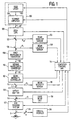
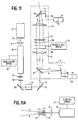
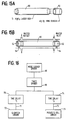
- FIGURE 1 shows the preferred configuration of the inventive apparatus.
- a laser unit 100 generates an initial laser beam B1.
- the laser unit 100 is of the type that can outputs a beam rapidly deflectable or scannable under electronic control in two dimensions to any location in an area defined by orthogonal X and Y axes.
- One such laser unit is described in detail in the co-pending, commonly-owned patent application for invention entitled “Two Dimensional Scanner-Amplifier Laser” (U.S. Patent Application Serial No. 07/740,004), and in the pertinent text reproduced below.
- the initial laser beam B1 comprises a sequence of laser pulses having a pulse repetition rate of about 100 to 50,000 pulses per second.
- Each laser pulse has a pulse duration which can be varied from 1 picosecond to about 5,000 picoseconds.
- the actual number of laser pulses used for a surgery is determined by the amount of tissue to be removed.
- the laser unit 100 includes a seed laser 102 and a scanner-amplifier laser 104.
- the laser media in both the seed laser 102 and the scanner-amplifier 104 is a Ti-doped Al 2 O 3 solid state laser crystal. Further details of the structure and operation of the laser unit 100 are set forth below.
- the laser beam B1 After emerging from the laser unit 100, the laser beam B1 passes through a computer-controllable, motorized zoom lens 106, which provides control over the diameter of the laser beam B1.
- the zoom lens 106 may be placed in a number of suitable positions along the optical path of the laser beam between the laser unit 100 and a target.
- the motor actuation of the zoom lens 106 may be by any known means, such as electrical gear drives or piezoelectric actuators.
- the preferred laser wavelength for the initial laser beam B1 is in the range of about 790-860 nm.
- the laser photon energy in the initial laser beam B1 is then converted in a first wavelength converter 108 (described below) by nonlinear wave mixing to a second laser beam B2 having approximately twice the initial laser beam photon energy, and a wavelength in the range of about 395-430 nm.
- the second laser beam B2 is passed through a second wavelength converter 110 (described below).
- the laser photon energy in the second laser beam B2 is again converted by nonlinear wave mixing to a third laser beam B3 having approximately four times the initial laser beam photon energy, and a wavelength in the range of about 198-215 nm.
- the initial laser beam B1 may be wavelength converted to the desired wavelength range of about 198-215 nm using a one-step converter (described below).
- the entire surgical laser apparatus includes a number of control and safety systems.
- the present invention includes means for monitoring and controlling the intensity of the beam, means for blocking the surgical beam in the event of a malfunction, means for monitoring and controlling the laser beam diameter and intensity profile, and means for verifying the two-dimensional (X-Y) scan position of the surgical beam.
- the third laser beam B3 passes through a beam intensity controller 112, the output of which is the surgical laser beam S.
- the beam intensity controller 112 permits regulation of the energy of each laser pulse so that the etch depth of each pulse may be precisely controlled.
- the beam intensity controller 112 is an electro-optical filter, such as an electrically activated Pockels cell in combination with an adjacent polarizing filter.
- the Pockels cell may include, for example, LiNbO 3 , or any other electro-optical crystal, such as potassium dihydrogen phosphate (KH 2 PO 4 ), also known as KDP.
- KH 2 PO 4 potassium dihydrogen phosphate
- Pockels cells are commercially available from several sources, including Medox Electro-Optics of Ann Arbor, Michigan. With the application of electric voltage across the electro-optical crystal in a Pockels cell, up to a half-wave retardation in the electric field vector of the incident laser beam can be generated.
- the linear polarization of a laser beam traversing the crystal can be retarded from a horizontal polarization to vertical, or vice versa.
- the polarizer placed adjacent the Pockels cell acts as a selector with respect to the incident beam from the Pockels cell.
- the beam impinging on the polarizer is orthogonally polarized by the Pockels cell, the beam will be essentially blocked by the polarizer. Lesser degrees of retardation generated by the Pockels cell will result in some of the light passing through the polarizer.
- the intensity of the incident laser beam can be electrically controlled.
- the beam intensity controller 112 is coupled to a computer control unit 114, which is suitably programmed to vary the intensity of the output surgical laser beam S as required for a particular surgical procedure.
- the degree of retardation as a function of applied electrical signal can be ascertained by standard calibration techniques.
- the preferred location of the beam intensity control unit 112 is as shown in FIGURE 1. However, the beam intensity control unit 112 can be placed at several suitable locations in the beam path between the laser unit 100 and a target.
- the intensity of the surgical beam S is regulated to have an ablation energy density of less than or equal to about 10 mJ/cm 2 .
- the present invention optionally provides for positive feed-back measurement of the beam intensity.
- a partially transmissive beam-splitting mirror 116 is placed after the beam intensity controller 112, and the reflected beam R i is directed to a beam intensity sensor 118.
- the beam intensity sensor 118 may be simply a photocell, although other elements, such as focussing optics, may be included.
- the intensity of the surgical laser beam S can be positively measured to verify the proper operation of the beam intensity controller 112.
- the output of the beam intensity sensor 118 as a function of intensity of the surgical laser beam S can be ascertained by standard calibration techniques.
- the inventive system also preferably includes a safety shutter 120, which is coupled to the computer control unit 114.
- the safety shutter 120 may be, for example, a mechanically-actuated shutter operated in a "fail-safe" mode.
- the safety shutter 120 may include a solenoid-actuated shield that is positively held open by application of electrical energy to the solenoid. Upon command of the computer control unit 114, or failure of the entire system, electrical energy to the solenoid is cut off, causing the solenoid to retract the shield into position to block the path of the surgical laser beam S.
- the safety shutter 120 may include a Pockels cell and polarizer configured as a light valve, with the Pockels cell biased with respect to the polarizer by application of an electrical voltage such that maximum light is normally transmitted by the combination. Cessation of the applied voltage will cause the output of the Pockels cell to become polarized orthogonal to the transmission direction of the polarizer, hence blocking the surgical laser beam S.
- the safety shutter 120 and the beam intensity controller 112 may be combined into a single unit.
- any other suitable means for quickly blocking the surgical laser beam S on command or in the event of system failure may be used to implement the safety shutter 120.
- the safety shutter 120 may be placed in a number of suitable positions along the optical path of the laser beam between the laser unit 100 and a target.
- the inventive system provides a partially transmissive beam-splitting mirror 122 that reflects part of the beam R d to a beam diameter sensor 124.
- the beam diameter sensor 124 may be placed in a number of suitable positions along the optical path of the laser beam between the laser unit 100 and a target.
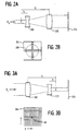
- the beam diameter sensor 124 preferably includes at least a diverging (concave) lens 200 and a converging (convex) lens 202 configured as a magnifying telescope (i.e., the two lenses have a common focal point, with the focal length f 2 of the converging lens 202 being greater than the focal length f 1 of the diverging lens 200, and having optical centers aligned with the incident laser beam in Its un-deflected position).
- the incident beam R d enters the diverging lens 200 and exits the converging lens 202.
- Such a configuration of lenses, while enlarging the incident beam, will also reduce the scan angle of the exiting beam.
- the resulting enlarged beam is directed to a low density, low contrast imaging device 204, such as a charge-coupled device (CCD) camera.
- a CCD camera having a 64 x 64 pixel array with two or more bits of contrast is suitable.
- Such cameras are available commercially.
- the two lens 200, 202 are chosen to expand the incident beam R d so that the largest possible diameter 206 for the beam just fits within the imaging device 204 (see FIGURE 2B, which shows only one row and one column of pixels).
- the size of the beam is determined by periodically addressing a central row and a central column of the imaging device 204 and counting the number of pixels on each sampled axis that have been illuminated.
- the beam diameter sensor 124 can determine whether the incident laser beam B1 is approximately circular and has the desired diameter. For example, if the number of pixels illuminated on each axis is 20 pixels, the beam will be known to have half the diameter of a beam that illuminated 40 pixels along both axes. As another example, if for any reason the beam has become elliptical, the number of pixels of the imaging device 204 illuminated along the X-axis will differ from the number of pixels illuminated along the Y-axis.
- the beam diameter sensor 124 can also be used to determine the intensity profile of the laser pulses, since each pixel in the beam diameter sensor 124 can generate an output indicative of the intensity of light incident to the pixel. By comparing pixel values from radially symmetric points in the pixel array, it can be determined if an incident laser pulse or series of pulses has the desired radially symmetric intensity profile, or if the pulses have developed "hot spots" of out-range intensity values.
- the output of the beam diameter sensor 124 is coupled to the computer control unit 114.
- the computer control unit 114 is in turn coupled to the motorized zoom lens 106, which provides control over the diameter of the laser beam B1.
- the computer control unit 114 is suitably programmed to vary the diameter of the laser beam as required for a particular surgical procedure.
- the output of the beam diameter sensor 124 as a function of beam diameter can be ascertained by standard calibration techniques.
- This configuration provides positive feed-back of the beam diameter emanating from the laser unit 100. If the beam diameter sensor 124 detects an out-of-range beam (either diameter or intensity profile), the computer control unit 114 can take appropriate action, including activation of the safety shutter 120.
- the inventive system provides a partially transmissive beam-splitting mirror 126 that reflects part of the beam energy R 1 to a beam location sensor 128.
- the beam location sensor 128 preferably includes at least a converging (convex) lens 300 and a diverging (concave) lens 302 configured as a reducing telescope (i.e., the two lenses have a common focal point, with the focal length f 2 of the diverging lens 302 being greater than the focal length f 1 of the converging lens 300, and having optical centers aligned with the incident laser beam in its un-deflected position).
- the incident beam R 1 enters the converging lens 300 and exits the diverging lens 302.
- Such a configuration of lenses, while reducing the incident beam will also increase the scan angle of the exiting beam.
- the resulting increased-scan angle beam is directed to a silicon photo-detector 304 which provides a voltage reading with respect to the two-dimensional (X-Y) location of an illuminating spot at the detector surface.
- a silicon photo-detector 304 which provides a voltage reading with respect to the two-dimensional (X-Y) location of an illuminating spot at the detector surface.
- detectors are commercially available from a variety of sources, including United Detector Technologies, UDT Sensors, Hawthorne, California.
- the output of the beam location sensor 128 is coupled to the computer control unit 114.
- Calibration of the voltage reading generated from the un-deflected incident beam position on the detector 304 will indicate the origin OR of the laser beam in the XY-scan plane. Any deflection of the beam from the origin OR will generate voltage readings indicative of the spot on the detector 304 surface illuminated by the laser beam. These voltage readings are calibrated against the indicated location of the surgical beam as set by the computer control unit 114. During operation, the output of the beam location sensor 128 would be sampled periodically (for example, about 1,000 times per second) and compared to a prepared calibration table in the computer control unit 114 to determine if the actual beam position matches the indicated position.
- This configuration provides positive feed-back of the beam position emanating from the laser unit 100. If the beam location sensor 128 detects an out-of-position beam, the computer control unit 114 can take appropriate action, including activation of the safety shutter 120.
- the preferred embodiment of the inventive surgical laser apparatus provides for safe and effective surgery by continuously monitoring all aspects of the condition of the surgical laser beam S, including beam intensity, diameter, and X-Y scan position.
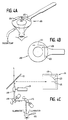
- a conventional suction ring 400 such as is shown in FIGURE 4A, is used to immobilize the eye.
- Such devices are commercially available, for example, from Steinway Instruments of San Diego, California.
- Such suction rings are further described, for example, in U.S. Patent No. 4,718,418 to L'Esperance, Jr.
- a suction ring 400 is normally applied to the white (sclera) region of the eye and connected to a low suction pressure sufficient to clamp the ring 400 to the eye, but not so great that the cornea is distorted.
- the use of such a ring 400 is well-known in the art.
- the present invention provides an eye tracking system 130 to compensate for relative movement between the eye and the surgical laser beam S. As shown in FIGURE 1, the eye tracking system 130 is placed in the path of the surgical laser beam S, preferably in close proximity to a target eye.
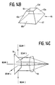
- a conventional suction ring 400 is provided with distinct marks 402, 404, 406 on the back of the ring facing the surgical laser system (see particularly FIGURE 4B).
- the marks may or may not be subdivided by cross-marks, for visual reference by a surgeon.
- the marks include an X-axis 402, an orthogonal Y-axis 404, and a radial axis 406.
- the marks are preferably made to be highly reflective of broadband illuminating light, and the background of the suction ring 400 is preferably flat black to enhance contrast and minimize extraneous reflections.
- the eye tracking system 130 includes a pair of steering mirrors 408, 410 each comprising a reflector mounted on a galvanometer scanner or similar actuator device which is controllable by a computer, and a rotational control device consisting of a dove prism 409 mounted with its rotational axes aligned with the surgical laser beam S (see FIGURE 4C).
- a motorized drive unit 411 is attached to a gear or bell drive designed to control the rotation of the dove prism 409. As is known, rotation of a dove prism will cause an exit beam to be rotated with respect to an incident beam.
- the steering mirrors 408, 410 are mounted with their rotational axis orthogonal to each other and situated such that the surgical laser beam S enters the eye tracking system 130, passes through the dove prism 409, bounces off of a first steering mirror 408 to the second steering mirror 410, and thence to a target cornea.
- the steering mirrors 408, 410 and the dove prism 409 therefore provide a means to "bias" the surgical laser beam S to compensate for movement of the eye relative to the surgical laser beam S.
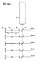
- Control of the steering mirrors 408, 410 and the dove prism 409 is provided by reflecting the image of the illuminated marks 402, 404, 406 on the suction ring 400 back up the optical path of the surgical laser beam S to a partially transmissive beam-splitting mirror 412, which directs the reflected image onto a tracking sensor 414 (other elements, such as focussing optics, may be included in the tracking sensor 414).
- the tracking sensor 414 includes three linear array sensors 416, 418, 420. Each linear array sensor 416, 418, 420 corresponds to one of the marks 402, 404, 406 on the suction ring 400, and is oriented orthogonally to the corresponding mark.
- each linear array sensor may be a linear reticon with about 1,024 or more sensing elements per inch. Such linear reticons are available commercially, such as from EG&G, Princeton, NJ.
- any movement of the suction ring 400 will result in a relative displacement of the reflected image of one or more of the marks 402, 404, 406 with respect to the corresponding linear array sensor 416, 418, 420.
- Such movement can be easily detected by comparing a stored initial position of each mark 402, 404, 406 with the position of each mark determined by periodically scanning the output of each linear array sensor 416, 418, 420.
- translational movements of the suction ring 400 in the X and Y directions, as well as rotational movements can be detected.
- the output of the tracking sensor 414 as a function of the positions of the reflected marks 402, 404, 406 can be ascertained by standard calibration techniques.
- the eye tracking system 130 may be provided with its own feedback control system to adjust the positions of the steering mirrors 408, 410 and the dove prism 409 to compensate for detected relative motion of the eye with respect to the surgical laser beam S.
- the eye tracking system 130 may be coupled to the computer control unit 114. Control of the eye tracking system 130 through the computer control unit 114 is preferred, since the computer control unit 114 can activate the safety features of the inventive system (e.g., the safety shutter 120) if the target eye is improperly aligned with the surgical laser beam S or if a failure occurs in the eye tracking system 130.
- the output of the tracking sensor 414 would be monitored, and the positions of the steering mirrors 408, 410 and the dove prism 409 adjusted accordingly.
- the inventive eye tracking system thus provides a means of improving the accurate placement of laser pulses to the cornea.
- the invention provides more precise detection of relative movement of the eye compared with systems using a natural indicator, such as the pupil or the sclera of the eye (which, in any case, could not indicate rotational movement).
- Another problem addressed and solved by the present invention is the proper deposition of laser beam energy on the cornea to ablate tissue to any desired depth while leaving an optically-smooth cornea surface after the laser surgery.
- it has been known to apply a laser beam in a raster scan or a circular or spiral scan pattern over the area of the cornea where tissue is to be removed see, for example, Figs. 3 and 4 of U.S. Patent No. 4,718,418 to L'Esperance, Jr.).
- a problem with such patterns when used with prior art laser systems is that such systems ablate tissue to a depth of about 0.3 to 15 microns or more per laser pulse.
- a typical procedure for laser etching of the cornea must remove from about 0.2 microns or less, up to about 50 microns of tissue. Since it is essentially impossible to accurately place each and every pulse so that it is perfectly contiguous to a neighboring pulse, ridges or grooves in the corneal surface of the same magnitude will result from the imperfect pattern of deposition of laser pulses. Accordingly, post-operative visual acuity will be reduced because of light scattering from the inhomogeneity of the tissue at the uneven interface.
- a problem with this approach is that, during photoablation, vaporized tissue material is expelled from each tissue site ablated by a laser pulse (the expelled tissue is known as "plume”). It is known that such expelled debris can scatter photons in an incoming laser beam (this is known as “shadowing”). As should be expected, this phenomena reduces the intensity of the beam. Thus, when laser pulses are overlapped as described above, a prior adjacent pulse will generate a plume that partially shadows or obscures the incoming laser beam of a subsequent adjacent laser pulse, causing nonuniformity of tissue ablation and hence irregularities on the cornea surface.
- the solution of the present invention to the problems of the prior art laser deposition patterns is to use a Gaussian, or, preferably, a super-Gaussian intensity profile for each laser pulse, and to deposit the pulses in a plurality of layers, each layer having a regular geometric pattern.
- the origin of each layer of the pattern is off-set by a specific distance in either the X or Y dimension from each prior, or subjacent, layer.
- the inventive pattern avoids the problem of plume by not overlapping the laser pulses of any one layer, and overcomes the problems of prior art ridge and groove formation by uniformly depositing laser energy over the surface to be etched. Because of the shallow etch depth of each laser pulse of the present invention (about 0.2 microns or less), etching can be stopped essentially at any point in the ablative process while leaving an optically smooth cornea surface.
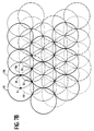
- each laser pulse creates an etch profile with an approximately circular cross-section with a radius r , which may typically range from about 0.02 mm to about 0.5 mm.
- the scan pattern programmed into the laser unit 100 lays down a pattern of pulses in a hexagonally-packed array of the type shown in FIGURE 7A. That is, the center A of each circular cross-section etch circle 700 of radius r is spaced a distance D, equal to 2 r , from the center A of each other etch circle 700.
- the pattern resulting from this simple criteria is a hexagonally-packed array of circles (the dotted hexagons shown in FIGURE 7A are for purposes of illustrating the packing pattern, and do not form any part of the etch profile).
- etch circles be non-overlapping and contiguous
- the invention encompasses slight overlapping and/or spacing of etch circles due to tolerance limits on positioning etch circles with a practical laser apparatus.
- a benefit of the hexagonally-packed array of etch circles is that the pattern is simple to program into the scanning control system of the laser unit 100 as a modified raster scan. If etch circle 702 having center A' is considered to be the origin for the initial first level pattern, the laser unit 100 need only move the laser beam in the X direction a distance of D to the center A for the next etch circle 704. Additional etch circles are created in the same manner for the first row, until the opposite edge of the area to be ablated is reached. Such precision of placement of etch circles is made possible by the highly accurate X-Y positioning capability of the laser unit 100, particularly when used in conjunction with the eye-tracking system described above.
- the laser beam is moved down in the Y direction a distance of about 0.866D (one-half the square root of 3 times D, representing the vertical distance between centers of adjacent rows), and left or right along the X direction by 1 ⁇ 2D (representing the horizontal distance between centers of adjacent rows).
- the beam is then either scanned backwards, or returned to the original "edge" of scanning and scanned forwards in the same manner as the first row.
- Each subsequent row is created in the same manner, until the bottom edge of the area to be ablated is reached, thus completing the first level layer.
- the accurate X-Y positioning capability of the laser unit 100 permits the etch circles for a particular layer to be deposited in any order, including randomly.
- a characteristic of the first level pattern shown in FIGURE 7A is that no circular etch substantially overlaps any other circular etch. Consequently, the problem of plume is minimized. While laying down only the first level pattern shown will result in ridges in the gaps between etch circles, because of the shallow etch depth used, the crest-to-trough distance of any ridge area R to the center A of any etch circle 700 will be at most about the same as the etch depth of a single etch (about 0.2 microns or less).
- the inventive method preferably lays down a second level pattern, comprising three etch layers.
- Each second level etch layer is an exact replica of the single etch layer of the first level pattern (i.e., an hexagonally-packed array of etch circles of radius r ).
- the origin of each of the three layers with respect to each other and to the first level layer is unique.
- each layer of the second level pattern is offset from the single layer of the first level pattern to even-out the distribution of laser energy across the cornea. This concept of off-setting subsequent layers in exact relationship with respect to an initial layer is in contrast to the prior art, which typically repeats the etching process by sweeping the laser beam across the ablation zone without reference to the exact location of each of the laser pulses.
- the origin of the first layer of the second level is set at point B1 (or an equivalent point; see below) of FIGURE 7A, which is one-half the distance D between the first level origin A' of etch circle 702 and the center of the adjacent etch circle 704.
- point B1 as an origin, the laser unit 100 is programmed to lay down an entire array of etch circles covering the area to be ablated, using the same rules for changing beam location as described above for the first level etch layer.
- the origin of the second layer of the second level is set at point B2 (or an equivalent point; see below) of FIGURE 7A, which is one-half the distance D between the first level origin A' of etch circle 702 and the center of the adjacent etch circle 706 in the next row.
- point B2 as an origin, the laser unit 100 is programmed to lay down an entire array of etch circles covering the area to be ablated, using the same rules for changing beam location as described above for the first level etch layer.
- the origin of the third layer of the second level is set at point B3 (or an equivalent point; see below) of FIGURE 7A, which is one-half the distance D between the center of etch circle 704 and the center of the adjacent etch circle 706 in the next row.
- point B3 as an origin, the laser unit 100 is programmed to lay down an entire array of etch circles covering the area to be ablated, using the same rules for changing beam location as described above for the first level etch layer.
- the resulting etch pattern for the second level will resemble the pattern shown in FIGURE 7B, which shows the first level centered at A' as thick-lined circles 715, the first layer centered at point B1 as solid circles 716, the second layer centered at point B2 as dotted circles 717, and the third layer centered at point B3 as dashed circles 718.
- the level one and two etch patterns may be repeated as needed to obtain the desired amount of ablation.
- the second level comprises three layers, all three layers need not be completed.
- the first layer of the second level can be started with its origin at any of the three points B1, B2, or B3, since all of these points are geometrically equivalent. More generally, equivalents of these three offset points exist throughout the grid of centers A defined by the initial first level layer. Thus, any equivalent offset point in the second level may be selected as the origin of one of the three layers comprising the second level.
- the overall etch profile determines which of the equivalent second level offset points will be selected to achieve maximum ablation where required in the surface being etched, and whether the desired degree of smoothness of finish requires completion of each of the second level layers. However, to ensure evenness of etching, it is generally desirable to complete all layers of the second level before additional levels of etching commence.
- first and second levels may instead be considered as a single etch pattern "unit" comprising four etch layers arranged to overlap in the manner shown in FIGURE 7B.
- etch patterns could be generated in a similar fashion by repeating levels one and two, using new origins.
- a characteristic of the geometry of an hexagonal packing array lends is that it lends itself to creation of repeating regular patterns.
- the origins B1, B2, and B3 for the second level etch layers comprise the midpoints of a triangle T1 connecting the centers of etch circles 702, 704, and 706.
- a second triangle T2 can be created by connecting the centers of etch circles 704, 706, and 708 (shown in dotted outline in FIGURE 7A). These two triangles comprise a symmetrical unit that is repeated throughout the pattern of centers A defined by the initial first level pattern.
- each of the triangles T1 and T2 can be subdivided into four smaller, equal-sized triangles, as shown in FIGURE 7A.
- the midpoints of each sub-triangle in a T1-T2 unit not shared with a similar T1-T2 type unit comprise twelve offset points C1-C12 that have equivalents throughout the grid of centers A defined by the initial first level layer.
- Each of these equivalent offset points C1-C12 can be used as an origin for a set of level one and level two etch patterns. That is, taking point C11 as an example, C11 can be selected as the center of a level one pattern. The level one pattern centered at C11 then defines a new grid for a corresponding level two pattern. Similarly, point C2 could then be selected as the center of another level one pattern. The level one pattern centered at C2 then defines a new grid for a corresponding level two pattern.
- any of them may be selected as the origin of one of the 48 layers (12 level one/level two sets) comprising the third level.
- the overall etch profile determines which of the equivalent third level offset points will be selected to achieve maximum ablation where required in the surface being etched, and whether the desired degree of smoothness of finish requires completion of each of the third level layers.
- the process of defining subsequent levels may be extended as necessary, by defining equivalent offset points based on repeating geometrical units determined by the grid of centers A defined by the initial first level layer.
- the general rule is to divide a previous level into additional triangles based on the grid defined by the initial first level layer. This is done by connecting three adjacent origins to form such triangles, and then using the midpoints of such triangles as new origins.
- the surface smoothness can be characterized in relation to the maximum etch depth of a single laser pulse.
- the maximum crest-to-trough distance of the etch patterns anywhere within the boundaries of the etched area will of course be 100% of the maximum crest-to-trough distance of a single etch circle.
- the maximum crest-to-trough distance of the overlapped etch patterns anywhere within the boundaries of the etched area will be at most about 53% of the initial first level pattern atone.
- the maximum crest-to-trough distance of the overlapped etch patterns anywhere within the boundaries of the etched area will be at most about 20% of the initial first level pattern alone. Since the crest-to-trough distance for the initial first level pattern is about 0.2 microns or less, and preferably about 0.05 microns or less, even the second level pattern may be sufficient to achieve the desired result.
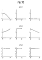
- FIGURE 7D shows a set of graphs showing the cumulative crest-to-trough distances of level one, level two, and level three etch patterns in accordance with the present invention.
- the Y-axis of each graph shows the cumulative etch depth in units of the maximum etch depth of a single laser pulse.
- the X-axis shows etch depth as a function of the distance from an etch circle center out along one of the three symmetry axes for an hexagonal array.
- FIGURE 7E shows the measurement axes used to compute the level two and level three crest-to-trough distances of FIGURE 7D.
- the notation for the endpoints of the X-axis of FIGURE 7D corresponds to the notation for the measurement points shown in FIGURE 7E.
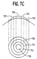
- the regular characteristics of the inventive deposition system are useful when etching the cornea in a "stepped pyramid" fashion (in terms of laser pulse count), with fewer etch circles deposited towards the periphery of the cornea and more etch circles deposited towards the center. As shown in FIGURE 7C, the resulting overall etch pattern typically resembles concentric circles (although other shapes are possible).
- the entire cornea is etched to the diameter of ring 720, using the etch patterns discussed above.
- a new origin at an equivalent offset point within ring 722 is chosen when the tissue in ring 720 has been etched to the desired degree. Etching continues over the entire cornea encompassed within the diameter of ring 722.
- a new origin at an equivalent offset point within ring 724 is chosen when the tissue in ring 722 has been etched to the desired degree. Etching continues over the entire cornea encompassed within the diameter of ring 724. The process continues in similar fashion until the center ring 726 is etched to the proper depth. (Note that the diameter of the laser pulses may be made smaller in the inner rings to provide a finer etching grid, in which case, a new initial first level pattern defining such a grid may be laid down and used in determining equivalent offset points for subsequent levels).
- the etch process could be done in reverse order, with center ring 726 etched first, then the area encompassed within the diameter of ring 724, then the area encompassed within the diameter of ring 722, and finally the area encompassed within the diameter of ring 720.
- the inventive system includes at least one wavelength converter to alter the wavelength of the initial laser beam B1 to the desired wavelength in the range of about 198-215 nm.
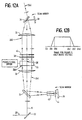
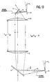
- FIGURE 5A A first example of one wavelength converter is shown in FIGURE 5A.
- the initial laser beam B1 emerging from the laser unit 100 is shown to have been scanned at an incident angle ⁇ 1 from its central position 500, which is defined as the center position of the total scan angle to be covered for an intended surgical operation.
- the laser beam is scanned in two dimensions, and hence two angular positions are needed to specify each unique beam position.
- the optical system is spherically symmetric. Thus, only one of the incident scan angles will be illustrated in the following discussion without loss of generality.
- a convex lens A is located at a distance f(A), the focal length of lens A from the pivot point of the scanned laser beam B1.
- the pivot point is inside the scanner-amplifier unit 104, at an equivalent position of the scan mirror near the exit dielectric mirror, as described below.
- a nonlinear optical crystal 502 is chosen such that phase matching angles exist with a proper crystal orientation so that a fundamental laser wavelength within a range of about 790-860 nm can be converted to its second harmonic at a wavelength in the range of about 395-430 nm.
- One possible such crystal is beta-Ba 2 BO 4 (beta barium borate).
- This crystal has a phase matching angle at about 26-30° for the wavelength range stated above, in type I phase matching conditions.
- the nonlinear crystal 502 is positioned at a distance f(A) from the lens A.
- the incident laser beam B1 is weakly focused at the crystal 502 with a choice of a long focal length for lens A.
- Another convex lens B located at the focal length f(B) of lens B from the crystal 502 re-collimates the beam into an emergent laser beam B2.
- both lenses A and B are coated for maximum transmission at laser lengths for which each transmits.
- the dimensions of the nonlinear crystal 502 are chosen such that the surface area where the incident laser beam B1 enters the crystal 502 is sufficiently large that the laser beam will not be cut off at the extremity of its scan angles.
- the length l of the crystal 502 is such that the conversion efficiency is to be optimized, in consideration of the walk off between the fundamental and the second harmonic beam, the group velocity dispersion, and the spectral bandwidth for the short duration laser pulses.
- the entrance surface of the nonlinear crystal 502 is coated for maximum transmission of the fundamental wavelengths and the exit surface is coated for maximum transmission of the second harmonic wavelengths.
- the scan angle ⁇ 1 of the incident laser beam B1 can be magnified or reduced by choosing the proper focal length for the lens B. If f(B) is smaller than f(A), the beam scan angle ⁇ 2 in FIGURE 5A will be magnified by a factor f(A)/f(B). On the other hand, if f(B) is larger than f(A), the beam scan angle ⁇ 2 will be reduced by a factor of f(A)/f(B).
- lens A provides two improvements in the harmonic conversion process: the laser photon density at the non-linear crystal 502 is increased due to the smaller beam area, and the laser beam orientation incident at the non-linear crystal 502 is maintained at all scan angles, thereby maintaining the phase matching conditions of the beam while it is being scanned.
- FIGURE 5A Another advantage of the embodiment shown in FIGURE 5A results from the change of location of the incident laser beam B1 through the nonlinear crystal 502 as the beam is scanned.
- a small amount of the laser beam is absorbed, resulting in a thermal gradient across the beam cross-section.
- This temperature variation at different portion of the incident beam B1 degrades the phase matching conditions, and places a limit on the conversion efficiency of the harmonic generation process.
- the thermal energy is effectively distributed over that area, and the average power loading in the crystal 502 is effectively reduced. If the area is sufficiently large, the laser pulses becomes non-overlapping. Reduction of pulse overlapping also results in an improved crystal damage threshold.
- the present invention overcomes the above prior art limitations, and provides an improved method of laser wavelength conversion to attain a higher conversion efficiency and a higher crystal damage threshold by scanning the laser beam across the nonlinear crystal 502. With the present invention, the repetition rate of the surgical beam can be extended to over 50,000 pulses per second.
- FIGURE 5B A second example of a wavelength converter is shown in FIGURE 5B,
- lens A and the nonlinear crystal 502 are similarly located as specified for FIGURE 5A, except that the crystal 502 is positioned slightly closer to lens A.
- a high reflective mirror 504 is located at a distance f(A) from lens A.
- the reflective mirror 504 has the characteristics of being highly reflective at the fundamental and the second harmonic wavelengths of the incident laser beam B1.
- a partially-transmissive beam-directing mirror 506 is included in the beam path, and is set at about 45° from the laser beam central position 500.
- the beam-directing mirror 506 is coated with dielectric thin films for high transmission of the fundamental wavelength, and high reflection of the second harmonic wavelength at near 45°.
- An incident laser beam B1 at an angle ⁇ 1 with the central position 500 passes through the beam-directing mirror 506, and is focussed by lens A on the nonlinear crystal 502.
- the beam is then reflected at the reflective mirror 504, passes through the crystal 502 a second time, and re-traces its beam path through the lens A.
- the second harmonic portion of the beam is then reflected by the 45° beam-directing mirror 506.
- the exit beam is now at an angle ⁇ 1 from a rotated central position 501, which is at two times the exact angle of the beam-directing mirror 506, and thus is about 90° with respect to the central position 500.
- the advantage of the structure and method shown in FIGURE 5B is that the non-linear crystal 502 is used twice by the fundamental beam. This method can almost double the conversion for the case of low conversion efficiency, in the case where the fundamental beam intensity is not significantly depleted in its first passage (e.g., when the wavelength conversion efficiency is less than about 30-40%).
- the residual laser photons of the initial laser beam B1 will not be used and may be filtered out by a dielectric coated mirror which has bandpass characteristics of high transmission at the second harmonic wavelengths of about 395-430 nm and blocking at the fundamental wavelengths of about 790-860 nm.
- the fundamental and the second harmonic waves can be separated spatially using dispersive optical elements, such as a high optical index prism or an optical grating.
- the filtering optics (not shown) can be placed in the beam path after the beam emerges from the first wavelength converter 108.
- the second laser beam B2 has a wavelength in the range of about 395-430 nm.
- the laser beam is directed into a second wavelength converter 110.
- the optical arrangement of the second wavelength converter 110 is almost identical to that of the first wavelength converter 108, which is illustrated in FIGURES 5A and 5B.
- the main difference between the two converters 108, 110 is in the optical crystal 502.
- the preferred nonlinear optical crystal is again beta-Ba 2 BO 4 (beta barium borate).
- the operating conditions are different in that the phase matching angles are at or close to 90° for type I phase matching.
- the optical faces of the crystal 502 are to be coated for maximum transmission at the front surface for the fundamental wave where the laser beam enters the crystal 502, and for maximum transmission at the second harmonic wave on the exit face.
- the optical characteristics of beta-Ba 2 BO 4 crystals impose a lower limit of the converted wave at about 200 nm for appreciable conversion efficiency.
- the third laser beam 83 emerging from the second wavelength converter 110 has a residual wavelength of about 390-430 nm.
- a wave filter means consisting of dispersive prism or optical gratings can be used to spatially separate the 200 nm wavelengths from the 400 nm wavelength contents.
- the wave filter (not shown) can be placed anywhere in the laser beam path after the second wavelength converter.
- first and second nonlinear optical crystals 502, 503 are placed in close proximity and are at the beam waist of the mildly focussed incident laser beam.
- the first crystal 502 is cut and oriented for phase match conditions to generate the second harmonic wave.
- the first crystal 502 is used to convert the fundamental wave into its second harmonic wave, and has a function as described above for the single-crystal embodiment of the first wavelength converter 108.
- the first crystal 502 is placed in front of the second crystal 503, facing the incident laser beam B1 emerging from the scanner amplifier.
- the portion of the laser beam B1 converted into the second harmonic wavelength of about 390-430 nm after passing through the first crystal 502 is then incident upon the second nonlinear crystal 503.
- the second crystal 503 is cut and oriented for phase matching as described above for the second wavelength converter 110, resulting in another step of second harmonic conversion, now using the 390-430 nm beam from the first crystal 502 as the fundamental wave.
- the second crystal 503 is placed in front of the first crystal 502.
- the incident laser beam B1 passes through the second crystal 503 with practically no conversion, since the crystal is oriented for phase matching for the 390-430 nm laser pulses emerging from the first crystal 502 after the pulses reflect off of the reflective mirror 504.
- the portion of the laser beam B1 converted into the second harmonic wavelength of about 390-430 nm after passing through the first crystal 502 is reflected and then incident upon the second nonlinear crystal 503.
- the second crystal 503 is cut and oriented for phase matching as described above for the second wavelength converter 110, resulting in another step of second harmonic conversion, now using the 390-430 nm beam from the first crystal 502 as the fundamental wave.
- lens B is properly coated for maximum transmission (anti-reflection) at the 200 nm range.
- the material for the lens is preferably UV quartz for good optical transmission.
- the modification is that the coating characteristics of the dielectric mirror 506 be highly reflective at about 198-215 nm at a 45° incident angle.
- a laser fundamental wavelength range of about 790-860 nm is illustrated for a Ti-doped Al 2 O 3 laser.
- a Ti:Al 2 O 3 laser has an operating range of about 680 nm to about 1200 nm. Therefore, the wavelength conversion apparatus and method described above can be applied to generate a slightly extended output wavelength range of about 396-600 nm after the first conversion, and about 198-300 nm after the second conversion, without loss of generality (the lower limits are about 396 nm and 198 nm, respectively, rather than about 340 nm and 170 nm, because of limitations of the nonlinear conversion crystal 502).
- the wavelength conversion apparatus and method may include sum frequency generation with two different laser wavelengths.
- the first wavelength converter 108 is structurally as described above. If the fundamental wavelength is selected to be about 790-900 nm, those wavelengths can be used to mix with the second harmonic wave of about 395-450 nm. However, the nonlinear optical crystal 502 in the second wavelength converter 110 has to be cut and oriented for phase matching conditions for the fundamental and the second harmonic waves in order to generate a laser wavelength of about 263-300 nm. If the fundamental laser wavelength from the laser unit 100 is in the range of about 790-900 nm, the laser wavelength at the output of the first wavelength converter 108 is modified by the wave mixing action of the second wavelength converter 110 to about 263-300 nm.
- the present invention includes a guide beam unit 132 (see FIGURE 1).
- the guide beam unit 132 is illustrated in greater detail in FIGURE 8.
- the guide beam unit 132 includes a low-power laser 800 with an output of preferably less than 1 milliwatt at initial output and preferably attenuated to the microwatt level for safe usage for direct viewing.
- the laser 800 in the guide beam unit 132 may be, for example, a HeNe laser or a semiconductor diode laser.
- the laser 800 generates a guide beam 801 which is conditioned optically so that it can be used as a indicator of the location of the surgical laser beam S. Additionally, the guide beam 801 can be used as an element for the alignment of the eye in preparation for surgical procedures.
- the guide beam 801 After emerging from the laser 800, the guide beam 801 the diameter of the guide beam 801 is expanded through a telescopic beam magnifier consisting of divergent lens 802 and a convergent lens 804 to about 10 mm.
- the collimated beam is then compressed by a weakly focussing lens 806, with a focal length of over 500 mm, at a distance of approximately the location of the patient's cornea.
- An axicon first and second prism pair 808, 810 are aligned with the expanded beam such that a divergent ring image with uniform intensity is produced after the first prism 808.
- the second prism 810 intercept the divergent ring and diffracts it to form a ring image 812 without divergence.
- the diameter of the ring image is controlled by the separation between the prism pair 808, 810: the farther they are separated, the larger is the ring.
- the position of the second prism 810 can be adjusted by a manual or motorized drive.
- the guide beam 801 emerges from the guide beam unit 132 and is denoted as beam G in FIGURE 1.
- the ring-shaped guide beam G from the guide beam laser unit 132 is aimed at a partially transmissive mirror 134 arranged so that the reflected guide beam G is coaxial with the un-deflected surgical laser beam S.
- a surgeon would move the patient's head and target eye until the guide beam G is roughly centered over the patient's cornea. The surgeon will then adjust the diameter of the ring image projected on to the patient's pupil, such that the ring diameter is only slightly less than the patient's pupil size. At that point, the patient will see the guide beam G, but not necessarily at a centered position.
- the patient is preferably situated in a relaxed position (e.g., supine), but with his or her head fixed within a cradle or fixture.
- Either the cradle or the entire operating table or chair is configured to be adjustable in fine increments about an X-Y plane perpendicular to the surgical laser beam S.
- the patient would then make fine adjustments of his or her own eye position with respect to the guide beam G by moving an actuator-control mechanism (e.g., a joy stick) for the cradle or operating table or chair, until the patient determines that the guide beam G appears to be at its brightest.
- an actuator-control mechanism e.g., a joy stick
- An advantage of the ring-shaped guide beam G of the present invention over a solid beam is that the light fall-off, or decrease in brightness, is greater for the ring-shaped beam than for the solid beam when either beam is not aligned with the patient's visual axis.
- the ring-shaped beam provides greater visual cues to the patient when the beam is off-axis.
- the surgeon may place a suction ring 400 over the patient's eye to immobilize it.
- the eye tracking system 130 is then activated to compensate for any subsequent motion of the eye. With the eye immobilized, the surgeon may then commence ablative surgery using the inventive laser system.
- an automatic feed-back control system may be used with the inventive system.
- a control system preferably includes a corneal profiler 136 which provides information to the computer control unit 114 sufficient to determine the necessary intensity and XY-scanning coordinates for the surgical laser beam S, and to otherwise control the delivery of pulses of laser energy to the cornea, in order to achieve a desired corneal surface profile.
- a suitable corneal profiler 136 is any device that measures the shape or an optical property of the eye so as to provide such information.
- a desired corneal surface profile may be obtained through ablation by a successive approximation technique.
- a measuring device is used to determine the change desired to be made in the profile of the corneal surface. Pulses of laser energy are delivered to the surface so as to bring about slightly less than the desired degree of alteration. The measuring device is then used again to determine the correction now needed to reach the desired profile. Further pulses of laser energy are provided accordingly to produce slightly less than the total calculated correction. This process is repeated until the ablated surface acquires the desired profile to a suitable degree of accuracy.
- Measurement devices suitable for the corneal profiler 136 are keratometers, which are known and commercially available. Examples of such devices are the "Photokeratoscope” manufacture by the Sun Contact Lens Company of Kyoto, Japan, and the “Corneascope” manufactured by International Diagnostic Instruments, Ltd., Broken Arrow, Oklahoma, USA. (See also S.D. Klyce, "Computer Assisted Corneal Topography", Invest. Ophthalmol. Vis. Sci. 25:1426-1435, 1984 for a comparison of these instruments and a method of using the "Photokeratoscope”). These devices work by imaging patterns, usually concentric rings, on the corneal surface. Preferably, the keratometer used as the corneal profiler 136 in the present method is modified slightly to increase the number of lines imaged on the central portion of the cornea, thus increasing the measurement resolution of the curvature of the central portion.
- the corneal profiler 136 receives a reflected image of a target cornea by means of a mirror 138, which is movable between an out-of-line position A and an in-line position B.
- a mirror 138 which is movable between an out-of-line position A and an in-line position B.
- an initial profile of the cornea can be determined by the corneal profiler 136.
- the output of the corneal profiler 136 is coupled to the computer control unit 114, and displayed to a surgeon.
- the computer control unit 114 determines the necessary settings and parameters, including pulse intensity, beam diameter, and target locations on the cornea, for the inventive laser system to create the desired ablation profile.
- the mirror 138 is then moved to position A, and the surgery commenced.
- the mirror 138 is periodically moved back into position B, the corneat profile is re-measured, the computer control unit 114 resets the laser system, the mirror 138 is retracted to position A, and the surgery re-commenced.
- the computer control unit 114 In determining the necessary settings and parameters, including pulse intensity, beam diameter, and target locations on the cornea, for the inventive laser system to create the desired ablation profile, the computer control unit 114 essentially prepares a three-dimensional contour map of the difference between (1) the cornea profile as measured and (2) the desired final shape of the cornea. Each point in this contour map may be described in terms of rectangular or polar coordinates, in known fashion. Starting with a selected pulse etch profile (i.e., a selected beam intensity and intensity profile), the etch depth of each pulse will be known (such information can be determined in advance by calibrating sets of profiles on corneal tissue). With a preselected etch depth, the contour map can be divided into a plurality of etch levels (for example, of the type shown in FIGURE 7B). Then, using a selected initial laser pulse diameter, each level of the contour map may be characterized in terms of the X-Y coordinates of a first level pattern of etch profiles of that diameter.
- a grid of 80 x 80 pulses will cover the entire maximum diameter.
- Arbitrarily selecting a single origin for such a grid means that each point on a level of the contour map can be defined in terms of X-Y coordinates. As the levels become smaller in size, the laser pulse diameter may be reduced accordingly, but the principal of mapping each level of the contour map to a grid of X-Y coordinates remains the same.
- This part of the disclosure is directed to a laser amplifier system utilizing a pair of scanning mirrors driven in tandem by piezo actuators.
- a control system is provided to direct a low-power laser beam while the beam is trapped and circulates between the pair of scanning mirrors. Each bounce of the laser beam between the mirrors discretely increases the power of the beam and changes the angle of exit of the beam from the amplifier, providing for precise angular beam exit control in two dimensions.
- a laser scanner-amplifier system 8 with Ti-doped sapphire Al 2 O 3 is used as the laser medium.
- the laser medium can be other tunable solid state laser materials, such as alexandrite, emerald, Cr:LiCaF, Cr:LiSrF, Cr:forsterite, color center lasers, or rare earth ion laser media, such as Nd, Pr, Er, Tm, Ho, or other transition metal ions such as Co, Ni in various solid state crystal hosts, including oxides or fluorides.
- a laser pulse train from a mode-locked Ti-doped Al 2 O 3 laser 10 in FIGURE 11 is to be used as a seeder to the amplifier scanner system.
- the laser pulse frequency of the mode-locked laser can be controlled by the round trip time of the laser pulse inside the mode-locked laser, and is at twice the driver frequency of the electrical signal applied to the mode-locked crystal. The frequency is chosen such that time period between adjacent pulses bears a preferred relationship with the arrangements of the optical elements inside the scanner-amplifier system.
- a continuous wave laser 12 such as, but not limited to, an argon gas laser operating at 514.5 nm or a frequency-doubled YAG or YLF laser at 532 nm and 527 nm respectively, can be used as the pump source.
- the pump laser beam 13 is focused into the mode-locked laser medium with a convergent lens 14.
- the arrangement of a laser-pumped mode-locked laser is well known in the art and a commercial model is available from Spectra-Physics, Mountain View, California.
- the mode-locked laser beam 15 passes through a set of beam conditioning optics 16, 18.
- the beam cross-section is expanded by a negative (concave) lens 16 and a positive (convex) lens 18 with their focuses coinciding to form an expansion telescope.
- the expansion ratio can vary from 2 to 10 by choosing the appropriate focal lengths of the optical elements 16 and 18, and is determined by the mode-matching requirement between the seed beam 15 and the spatial mode of the amplifier cavity. By centering the lenses along the laser beam, minimum beam distortion and good beam collimation can be achieved as the seed beam 15 exits the optical element 18.
- the seed beam is directed by high reflective mirrors 20 and 22 into the amplifier cavity.
- the beam first enters the cavity through a dielectric coated mirror 24 which has the optical characteristics that a pi-polarized laser beam with the electric field vector horizontal to the plane of incidence has over 96% transmission, and a pi-polarized laser beam with the electric field vector vertical to the plane of incidence has over 99% reflectability.
- a dielectric coated mirror 24 which has the optical characteristics that a pi-polarized laser beam with the electric field vector horizontal to the plane of incidence has over 96% transmission, and a pi-polarized laser beam with the electric field vector vertical to the plane of incidence has over 99% reflectability.
- Such thin-film polarizer elements are supplied by Burleigh NorthWest, Fishers, New York.
- the scanner-amplifier cavity 8 is confined between the scanner mirrors 26 and 28, both of which are highly reflective mirrors.
- the scanner mirrors 26, 28 are each mounted on a gimbal mount 29 with 90° tilts in both the horizontal and the vertical (X-Y) directions.
- the design of the gimbal mount can be illustrated as a mirror mount model number MM-1 manufactured and supplied by the Newport Corporation, Fountain Valley, California, with appropriate modifications to shorten the pivot point distance and increase the spring force.
- the X-Y tilts are achieved by piezoelectric actuators 31 with a material such as PZT which can have a linear travel of 40 microns of full scan range at about 1000 Hz, and at higher frequencies with smaller travel range.
- Such piezo actuators are supplied by a number of suppliers, including Burleigh Instruments, Fishers, New York.
- the scan mirrors 26 and 28 are driven in the same direction at the same angular degree either independently or in tandem in both the X and Y directions.
- the operating characteristics of the piezo actuators may have small variations.
- the overall scan angles of the laser beam as emerged from the scanner-amplifier is to be calibrated against the voltage applied to the piezo actuators 31, taking into the account the small amount of hysteresis from the piezoelectric effect.
- a pair of concave lenses 30 and 32 are included inside the scanner-amplifier cavity.
- the focal lengths of the lenses 30 and 32 are such that the focal length of lens 30 is chosen to be as large as possible, yet the size of scanner-amplifier is to be practical and convenient for use, and the focal length of lens 32 will be as short as possible, yet not so short as to cause optical break-down at its focal point.
- the relative locations of the lenses 30, 32 and end mirrors 26 and 28 are such that the mirrors 26 and 28 are to be at the focal point of the lenses 30 and 32, respectively, and the separation between the lenses is to be the sum of their focal lengths.
- Another dielectric-coated mirror 34 which has similar characteristics as mirror 24, is used as a turning mirror and also as an exit mirror where the laser beam 15, intensity amplified and scan-angle amplified, emerges from the scanner-amplifier unit 8.
- Pockels cell 36 which consists of LiNbO 3 or other electro-optical crystal such as KDP.
- Pockels cells are commercially available from several sources, one such source is Medox Electro-optics, of Ann Arbor, Michigan. With the application of electric voltage across the electro-optical crystal, a half-wave retardation in the electric field vector of the laser beam can be generated, which turns the linear polarization of a laser beam traversing the crystal, from a horizontal polarization to vertical, and vice versa.
- a half-wave retardation plate 38 placed next to the Pockels cell 36, is for adjusting the polarization of the beam before it reaches the mirror 34, so that the beam will either stay inside the cavity or exit the cavity at mirror 34.
- a thin etalon 40 with partial reflective coating on both faces at the laser wavelength is for controlling the gain bandwidth of the seed beam 13.
- the wavelength width of the laser beam is reduced accordingly, compared to the seed beam bandwidth.
- the pulse duration is lengthened due to the reduced spectral content in the laser pulse.
- Another method of expanding the pulse duration can be achieved by stretching the pulse spatially with an optical grating, before the pulse is injected into the beam path at location 21 shown in drawing FIGURE 11.
- a commercial pulse compressor unit consisting basically of a single-mode fiber and grating pair, can be placed at location 21 instead of just the optical grating.
- Such a unit is manufactured by Spectra-Physics Lasers, Mountain View, California.
- the output laser pulse can be varied from a minimum which is that of the seed pulse, which is about 1 picosecond in the case of Ti:Al 2 O 3 as the laser medium in the mode-locked laser, to as much as several hundred picoseconds.
- a laser gain medium 42 is located near the scanner mirror 26.
- a cavity aperture 44 which has a fixed or adjustable iris with two translational degrees of freedom for proper centering with the fundamental laser mode is located inside the cavity.
- the laser media is optically pumped by a laser source 48 which will be described hereinafter in more detail.
- the second embodiment provides enhancement of the laser beam intensity inside the scanner cavity, such that the beam intensity increases by extracting energy stored in the gain medium 42.
- an angle is being scanned in the horizontal plane (the X-plane).
- a scan voltage is applied to both piezo actuators 31 for positioning the gimbal mirror mounts for scan mirrors 26 and 28 in the same direction to the same degree; as an example, both pushing the mirrors forward as shown in FIGURE 11.
- a half-wave voltage electrical wave form signal is applied to the Pockels cell, as illustrated in FIGURE 12B.
- the time sequence from 2(i) to 2(vi) marks the time development of the optical retardation of the Pockels cell 36.
- a voltage is to start at time 2(ii), and the optical retardation reaches half-wave at time 2(iii).
- the voltage is turned off at time 2(iv), and zero retardation is reached at time 2(v).
- the time duration between 2(ii) and 2(iii) is referred to as the rise time of the Pockels cell for a half-wave retardation.
- the duration between 2(iv) and 2(v) is the fall time for
- the seed laser pulse Since the seed laser pulse is in the picosecond range, the spatial extent of the laser energy is localized in the range of millimeters.
- the cavity distance between scan mirrors 26 and 28 is, for practical purpose, in the range of tens of centimeters to tens of meters. Therefore, for all practical purpose, the laser pulse can be considered localized and is represented by markers 2(i) to 2(vi) as it travels through the scanner-amplifier cavity.
- the seed laser beam, at time 2(i) travels towards the scanner-amplifier cavity, and enters through the thin film polarizer mirror 24. As illustrated in FIGURE 12A, the beam 15 has a linear polarization with the electric field vector in the horizontal direction, as indicated by the arrow.
- the beam passes through the lens 30, and is focussed at a point before lens 32 which collimates the beam due to the confocal arrangement of the lenses 30 and 32.
- the Pockels cell (PC) voltage is at the zero level, and the polarization of the seed beam is not changed.
- the Pockels cell voltage then turns on at time 2(ii), right after the laser pulse exits the PC crystal.
- the polarization changes by 90° after passing through the half-wave plate 38, and is now vertical, as indicated by a small circle on the beam path.
- the beam is then reflected by the thin film polarizer mirror 34 directing the beam towards the scan mirror 28.
- FIGURE 13 the beam path and the angle of incidence at mirrors 26 and 28 are illustrated.
- a voltage V 1 is applied to the piezo actuator 31, which induces a scan angle of ⁇ 1 from its zero degree incidence, at which the mirror is at the normal incidence with the incoming seed beam.
- the reflected beam is at an angle, 2 times ⁇ 1 from the incoming beam.
- the beam is reflected at mirror 28.
- the vertical polarization of the beam changes by 90° after passing through the half-wave plate 38.
- the PC voltage reaches half-wave retardation at 2(iii) (see FIGURE 12B) before the laser pulse reaches the PC.
- the polarization is rotated 90° and is now vertical.
- the lens 30 re-collimates the laser beam 15 and the thin film polarizer 24 is now at high reflection with respect to the vertically polarized beam.
- the beam 15 then travels towards the laser gain medium 42 and the cavity aperture 44.
- the following discussion is directed to ejecting the laser beam after only one reflection from each of the mirrors 26 and 28; however it should be understood that it is contemplated that a plurality of reflections occur from each mirror within the device prior to the beam exiting therefrom.
- the PC voltage turn-off starts after the beam emerges from the PC at time 2(iv), and the retardation is zero at 2(v) before the beam reaches the PC on its return trip from the scan mirror 26.
- the vertical polarization remains vertical after passing the PC, and is rotated to horizontal after the half-wave plate 38.
- the thin film polarized mirror is now transmissive for the laser beam, and the laser beam emerges from the amplifier-scanner of the invention with a scan angle resulting from the sum of the effects of the scan angles ⁇ 1 and ⁇ 2 from the scan mirrors 28 and 26 respectively.
- invention makes use of the scan mirrors 26 and 28 repeatedly for one or more round trips of the beam inside the cavity to amplify and precisely direct the beam angle before exiting mirror 34.
- the PC voltage turn-off at times 2(iv)-2(v), is to be applied at the last leg after one or more round trips between the two scan mirrors 26 and 28.
- the voltage turn-off is postponed, as in the illustration in FIGURE 12A, the polarization of the reflected beam from mirror 26 is rotated to horizontal after the PC, which is still at its half-wave voltage, and back to be vertical again after the half-wave plate 38. Therefore, the mirror 34 is highly reflective. The beam is trapped inside the cavity, and the beam angle increases with each reflection with either of the scan mirrors.
- the optical arrangement enhances the overall scan angle of the beam with a power multiplying enhancement factor.
- M f (30) /f (32) where f (30) , f (32) are the focal lengths of the lenses 30 and 32, respectively.
- the angle of incidence on mirror 28 is ⁇ 1
- the angle of incidence on mirror 26 is: ⁇ 1 /M + ⁇ 2 .
- the output beam would have a scan angle of: 2 ⁇ ( ⁇ 1 + M ⁇ ⁇ 2 ).
- the final scan angle of the exit beam is; 2N x ( ⁇ 1 + M ⁇ ⁇ 2 ).
- the intended scan angle will be achieved with the smallest number of optical surface contacts. If the scan mirrors have identical gimbal mounts 29 and piezo actuators 31, the mirrors can be scanned in tandem, and ⁇ 1 and ⁇ 2 will be substantially equal. The optical loss due to scattering from all the optical elements inside the cavity is reduced by the factor: (M+1)/2
- the scan angle is amplified by 20 times more than the amplification of the scan angles from two like but uncoupled piezo mirrors.
- the pump source 48 of the Ti:Al 2 O 3 in the amplifier cavity in FIGURE 11 consists of two major components, namely, a Nd-doped YAG or YLF laser which is continuously pumped by arc lamps such as Kr or Ar gas lamp, which is supplied by ILC Technology, Sunnyvale, California, or by semiconductor diode arrays with the emission laser wavelength to match the absorption band of Nd-doped YAG or YLF.
- arc lamps such as Kr or Ar gas lamp
- semiconductor diode arrays with the emission laser wavelength to match the absorption band of Nd-doped YAG or YLF.
- Several hundred to over one thousand watts of continuous wave laser output power from Nd:YAG is attainable with multiple lamp-pumped laser heads inside a laser cavity.
- Such lasers are supplied by Lasermetric, Orlando, Florida, and a number of other industrial YAG laser suppliers.
- the Ti ion has an absorption band centered at about 520 nm, with a full width at half maximum of about 100 nm.
- the second harmonic wavelengths of the Nd-doped YAG and YLF are centered around 532 nm and 527 nm, respectively, and both are suitable as a pump source.
- the output laser beam 55 of a high power, acoustic-optical switched, Nd-doped YAG or YLF laser beam source 56 is directed to a series of partially reflecting beam splitters 57, which are coated with dielectric so that, at the 45° incidence, they all have high transmission for the second harmonic wavelength, and each succeeding splitter is highly reflective at the fundamental wavelength of the laser source 56, so that the laser beam power is distributed equally among each branch when they are directed towards the SHG crystals 60.
- the crystal 60 is chosen for high nonlinear coefficient, good acceptance angle, and high tolerance to a temperature gradient.
- KTP is among the top choices as a SHG crystal for conversion at 1.04 to 1.06 microns.
- a convex lens 58 can be inserted between each splitter 57 and each SHG crystal 60, such that the crystal is at the focal distance f (58) from the lens, where the beam cross-section is the smallest and the laser power density is the highest.
- the focal length of the lens is chosen to optimize for the acceptance angle of the SHG crystal.
- a spherical concave mirror 62 that is highly reflective at both the fundamental and the second harmonic wavelength is placed at the radius of curvature of the mirror 62, R (62) , from the first surface of the crystal, where the laser beam enters the crystal. This optical arrangement allows for the return beams of both the fundamental and the second harmonic to retrace the beam path of their first passage in the crystal, and ensure a good beam overlapping in the crystal even though there may be walk-off between the beams after their first pass.
- the combiner 64 is a six-face optical element which has four sides 63a, 63b, 63c and 63d, each of which form a 45° angle with the base face 67, and a top face 65 which is parallel to its bottom face 67.
- the side faces are coated for high reflectivity at 45° at the second harmonic wavelength, and the top and bottom faces are coated with an anti-reflection coating at the second harmonic wavelength.
- the five beams from FIGURE 14A can be reflected off the side faces of the combiner 64, and one beam (beam 2) in FIGURE 14C can transmit through the parallel faces.
- the beams are adjusted such that they re-collimated and are parallel with each other.
- a convex lens 66 is centered symmetrically in the beam path, and focuses the five beams into a common focal point.
- This optical element 66 can be a replacement of or an equivalent to the element 46 of FIGURE 11.
- additional beams can be combined with a spatial combiner with additional facets on the combiner.
- a hexagon instead of a square top, can combine up to 7 beams.
- the facets can be formed on more than one layer, such as 4 facets on the top tier and 6 facets on the second tier.
- the pump beam is absorbed by the laser active ions in the crystal host.
- the energy distribution in the laser medium is a negative exponential function, with a maximum at the entrant face.
- the laser medium in the invention is to be in a cylindrical laser rod form.
- a conventional laser rod is mounted with the end faces outside of the contact with the coolant.
- the preferred embodiment consists of a Ti:A1203 laser rod with a recessed collar 50.
- a thin wall tube made of undoped sapphire 52 is to fit at the end sections of the laser rod. The tube piece is glued to the laser rod, and the whole has a cylindrical shape as shown in FIGURE 15B.
- FIGURE 15B A water flow channel around the laser medium and the extension is shown in FIGURE 15B, in which the water inlets and outlets are shown schematically.
- O-rings 54 are retained in such a manner that the coolant is sealed from coming into contact with the flat laser surfaces of the laser rods.
- the tube extension allows the whole laser medium to be in contact with the liquid coolant. Using the same material in the extension tube also minimizes stress as a result of a difference in thermal expansion coefficient, with temperature variation in the whole assembly.
- an additional pump source can be applied through mirror 24 collinear with laser path from pump source 48, such that the laser media is pumped from both ends.
- additional laser media is to be included in front of the scan mirror 28, and a pump configuration identical to optical elements 46 and 48, pumping one end of the laser medium, or pumping from both ends of the laser medium, is to be applied to the laser medium near mirror 28.
- Multi-kilohertz laser operation is achieved with the following method.
- a synchronized electrical wave form is tapped from the mode locker driver 66.
- the synchronized signal can be divided electrically by a timer divider circuit 68, as shown diagrammatically in FIGURE 16.
- the resultant frequency output of the timer-divider determines the laser frequency of the scanner-amplifier system.
- the output electrical signal of the divider box is then time-delayed through delay generators 70 and 74, commercially available from Stanford Research Systems, Sunnyvale, California.
- One of the delayed signals 71 is fed into a Q-switched driver 72 in the pump laser 48, and a second time-delayed signal 75 is fed into the Pockels cell driver 76.
- FIGURE 17 The timing of the electrical signals and the laser events are illustrated in FIGURE 17.
- multi-megahertz (30-200 MHz) mode locked laser pulses are represented by equally spaced laser spikes at time intervals equal to twice the mode locker driver frequency.
- electrical signals at multi-kilohertz 1,000-50,000 Hz is generated at the output of the timer-divider box, as represented by the trace 7(b).
- the Q-switch driver for the pump laser is turned on, in trace 79(c), generating a short pulse of the second harmonic laser pump pulse at a time delay T r , corresponding to the build up of the pump pulse, a characteristic of the pump configuration, and the gain factor at the pump laser medium.
- the second harmonic pump pulse is absorbed in the Ti:Al 2 O 3 laser medium, in trace 7(d).
- the Pockels cell is switched on at a time delay T 2 relative to a synchronized timer-divider signal, which is the pulse after the one that triggers the Q-switch driver.
- the time delay T 2 is determined by the actual location of the seed laser pulse from the mode locked laser, as aforementioned along with the discussion of FIGURE 12A.
- the delay time T 1 is to be adjusted so that the peak of the population inversion is to occur when the Pockels cell crystal reaches the half-wave retardation point of 2(iii) as shown in FIGURE 12B.
- the laser surgical system of the present invention can perform numerous types of surgical procedures on the cornea.
- two types of laser tissue interaction are particularly suited for the inventive system:
Landscapes
- Physics & Mathematics (AREA)
- Optics & Photonics (AREA)
- Engineering & Computer Science (AREA)
- Plasma & Fusion (AREA)
- Mechanical Engineering (AREA)
- Health & Medical Sciences (AREA)
- Electromagnetism (AREA)
- Ophthalmology & Optometry (AREA)
- Nonlinear Science (AREA)
- Vascular Medicine (AREA)
- General Physics & Mathematics (AREA)
- Surgery (AREA)
- Biomedical Technology (AREA)
- Heart & Thoracic Surgery (AREA)
- Nuclear Medicine, Radiotherapy & Molecular Imaging (AREA)
- Life Sciences & Earth Sciences (AREA)
- Animal Behavior & Ethology (AREA)
- General Health & Medical Sciences (AREA)
- Public Health (AREA)
- Veterinary Medicine (AREA)
- Laser Surgery Devices (AREA)
- Prostheses (AREA)
Applications Claiming Priority (3)
| Application Number | Priority Date | Filing Date | Title |
|---|---|---|---|
| US78842491A | 1991-11-06 | 1991-11-06 | |
| US788424 | 1991-11-06 | ||
| EP92924366A EP0614388B1 (de) | 1991-11-06 | 1992-11-05 | Vorrichtung für hornhautchirurgie |
Related Parent Applications (1)
| Application Number | Title | Priority Date | Filing Date |
|---|---|---|---|
| EP92924366A Division EP0614388B1 (de) | 1991-11-06 | 1992-11-05 | Vorrichtung für hornhautchirurgie |
Publications (2)
| Publication Number | Publication Date |
|---|---|
| EP1159986A2 true EP1159986A2 (de) | 2001-12-05 |
| EP1159986A3 EP1159986A3 (de) | 2004-01-28 |
Family
ID=25144448
Family Applications (2)
| Application Number | Title | Priority Date | Filing Date |
|---|---|---|---|
| EP01119190A Withdrawn EP1159986A3 (de) | 1991-11-06 | 1992-11-05 | Verfahren und Vorrichtung für Hornhautchirurgie |
| EP92924366A Expired - Lifetime EP0614388B1 (de) | 1991-11-06 | 1992-11-05 | Vorrichtung für hornhautchirurgie |
Family Applications After (1)
| Application Number | Title | Priority Date | Filing Date |
|---|---|---|---|
| EP92924366A Expired - Lifetime EP0614388B1 (de) | 1991-11-06 | 1992-11-05 | Vorrichtung für hornhautchirurgie |
Country Status (9)
| Country | Link |
|---|---|
| US (4) | US6210401B1 (de) |
| EP (2) | EP1159986A3 (de) |
| JP (1) | JPH07503382A (de) |
| AT (1) | ATE218904T1 (de) |
| AU (1) | AU671607B2 (de) |
| CA (1) | CA2123008C (de) |
| DE (1) | DE69232640T2 (de) |
| RU (1) | RU94030810A (de) |
| WO (1) | WO1993008877A1 (de) |
Cited By (28)
| Publication number | Priority date | Publication date | Assignee | Title |
|---|---|---|---|---|
| WO2003057100A3 (en) * | 2002-01-10 | 2004-03-18 | Katana Technologies Gmbh | Device and procedure for refractive laser surgery |
| WO2005039462A1 (de) | 2003-10-23 | 2005-05-06 | Carl Zeiss Meditec Ag | Laserbearbeitung |
| WO2005048896A1 (de) | 2003-11-14 | 2005-06-02 | Carl Zeiss Meditec Ag | Adapter zum koppeln einer laserbearbeitungsvorrichtung mit einem objekt |
| DE10354025A1 (de) * | 2003-11-19 | 2005-06-02 | Carl Zeiss Meditec Ag | Adapter zum mechanischen Koppeln einer Laserbearbeitungsvorrichtung mit einem Objekt |
| WO2006090217A1 (en) * | 2005-02-25 | 2006-08-31 | 20/10 Perfect Vision Optische Geraete Gmbh | Device and mehtod for aligning an eye with a surgical laser |
| WO2008040436A1 (de) * | 2006-09-29 | 2008-04-10 | Carl Zeiss Meditec Ag | Vorrichtung und verfahren zur materialverarbeitung unter verwendung eines transparenten kontaktelements |
| DE102007053283A1 (de) | 2007-11-08 | 2009-05-14 | Carl Zeiss Meditec Ag | Behandlungsvorrichtung zur operativen Fehlsichtigkeitskorrektur eines Auges, Verfahren zum Erzeugen von Steuerdaten dafür und Verfahren zur operativen Fehlsichtigkeitskorrektur eines Auges |
| DE102007053281A1 (de) | 2007-11-08 | 2009-05-14 | Carl Zeiss Meditec Ag | Behandlungsvorrichtung zur operativen Fehlsichtigkeitskorrektur eines Auges, Verfahren zum Erzeugen von Steuerdaten dafür und Verfahren zur operativen Fehlsichtigkeitskorrektur eines Auges |
| DE102008017293A1 (de) | 2008-04-04 | 2009-10-08 | Carl Zeiss Meditec Ag | Verfahren zum Erzeugen von Steuerdaten für die Augenchirurgie sowie augenchirurgische Behandlungsvorrichtung und -verfahren |
| DE102009005482A1 (de) | 2009-01-21 | 2010-07-22 | Carl Zeiss Meditec Ag | Vorrichtung und Verfahren zum Erzeugen von Steuerdaten zur operativen Fehlsichtigkeitskorrektur eines Auges |
| DE102009009382A1 (de) | 2009-02-18 | 2010-08-19 | Carl Zeiss Meditec Ag | Vorrichtung und Verfahren zum Erzeugen von Steuerdaten zur operativen Fehlsichtigkeitskorrektur eines Auges und Fehlsichtigkeitskorrekturverfahren |
| EP2298255A1 (de) | 2006-11-10 | 2011-03-23 | Carl Zeiss Meditec AG | Planungseinrichtung zum Vorbereiten von Steuerdaten für eine Behandlungsvorrichtung zur operativen Fehlsichtigkeitskorrektur, Behandlungsvorrichtung zur operativen Fehlsichtigkeitskorrektur und Verfahren zum Vorbereiten von Steuerdaten dafür |
| US7982169B2 (en) | 2006-02-20 | 2011-07-19 | Wavelight Ag | Apparatus and method for detecting the focal position of an optical system and opthalmological treatment apparatus |
| WO2012007552A1 (de) | 2010-07-14 | 2012-01-19 | Carl Zeiss Meditec Ag | Steuerdatenerzeugung für die augenchirurgische fehlsichtigkeitsbehandlung |
| EP2529712A1 (de) | 2006-11-10 | 2012-12-05 | Carl Zeiss Meditec AG | Behandlungsvorrichtung zur operativen Fehlsichtigkeitskorrektur eines Auges und Verfahren zum Erzeugen von Steuerdaten dafür |
| WO2013045564A1 (de) | 2011-09-30 | 2013-04-04 | Carl Zeiss Meditec Ag | Behandlungsvorrichtung zur operativen fehlsichtigkeitskorrektur eines auges, verfahren zum erzeugen von steuerdaten dafür und verfahren zur operativen fehlsichtigkeitskorrektur eines auges |
| WO2013057318A1 (de) | 2011-10-21 | 2013-04-25 | Carl Zeiss Meditec Ag | Erzeugung von schnittflächen in einem transparenten material mittels optischer strahlung |
| WO2013056867A1 (de) | 2011-10-21 | 2013-04-25 | Carl Zeiss Meditec Ag | Erzeugung von schnitten in einem transparenten material mittels optischer strahlung |
| US8623001B2 (en) | 2005-08-25 | 2014-01-07 | Carl Zeiss Meditec Ag | Contact glass for ophthalmologic surgery |
| US8685006B2 (en) | 2006-11-10 | 2014-04-01 | Carl Zeiss Meditec Ag | Treatment apparatus for surgical correction of defective eyesight, method of generating control data therefore, and method for surgical correction of defective eyesight |
| US8944601B2 (en) | 2005-08-25 | 2015-02-03 | Carl Zeiss Meditec Ag | Contact glass for ophthalmic surgery |
| US9265658B2 (en) | 2004-02-25 | 2016-02-23 | Carl Zeiss Meditec Ag | Contact element for laser machining |
| DE102014014567A1 (de) | 2014-09-29 | 2016-03-31 | Carl Zeiss Meditec Ag | Erzeugung von speziellen Schnitten in einem transparenten Material mittels optischer Strahlung |
| DE102014014565A1 (de) | 2014-09-29 | 2016-03-31 | Carl Zeiss Meditec Ag | Erzeugung von Schnitten in einem transparenten Material mittels optischer Strahlung |
| DE102016116267A1 (de) | 2016-08-01 | 2018-02-01 | Carl Zeiss Meditec Ag | Vorrichtung zur operativen Fehlsichtigkeitskorrektur eines Auges und Verfahren zum Erzeugen von Steuerdaten hierfür |
| US10675183B2 (en) | 2014-09-29 | 2020-06-09 | Carl Zeiss Meditec Ag | Creating cuts in a transparent material using optical radiation |
| US10799394B2 (en) | 2016-04-05 | 2020-10-13 | Amo Development, Llc | Patient interface device for laser eye surgery having light guiding structure for illuminating eye |
| DE102006053118B4 (de) | 2006-11-10 | 2022-02-17 | Carl Zeiss Meditec Ag | Planungseinrichtung zum Vorbereiten von Steuerdaten für eine Behandlungsvorrichtung zur operativen Fehlsichtigkeitskorrektur, Behandlungsvorrichtung zur operativen Fehlsichtigkeitskorrektur und Verfahren zum Vorbereiten von Steuerdaten dafür |
Families Citing this family (419)
| Publication number | Priority date | Publication date | Assignee | Title |
|---|---|---|---|---|
| US6099522A (en) * | 1989-02-06 | 2000-08-08 | Visx Inc. | Automated laser workstation for high precision surgical and industrial interventions |
| US5722427A (en) * | 1993-05-10 | 1998-03-03 | Eyesys Technologies, Inc. | Method of refractive surgery |
| DE69232640T2 (de) * | 1991-11-06 | 2003-02-06 | Shui T Lai | Vorrichtung für hornhautchirurgie |
| US5740815A (en) * | 1995-06-07 | 1998-04-21 | Alpins; Noel A. | Method for surgically achieving minimum astigmatism measured refractively and topographically |
| US6090100A (en) | 1992-10-01 | 2000-07-18 | Chiron Technolas Gmbh Ophthalmologische Systeme | Excimer laser system for correction of vision with reduced thermal effects |
| DE4232915A1 (de) * | 1992-10-01 | 1994-04-07 | Hohla Kristian | Vorrichtung zur Formung der Cornea durch Abtragen von Gewebe |
| US6716210B2 (en) * | 1992-12-03 | 2004-04-06 | Lasersight Technologies, Inc. | Refractive surgical laser apparatus and method |
| CO4230054A1 (es) | 1993-05-07 | 1995-10-19 | Visx Inc | Metodo y sistemas para tratamiento con laser de errores refractivos utilizando formacion de imagenes de desplazamiento |
| US6319247B1 (en) | 1993-05-07 | 2001-11-20 | Visx, Incorporated | Systems and methods for corneal surface ablation to correct hyperopia |
| US5645550A (en) * | 1994-04-08 | 1997-07-08 | Chiron Technolas Gmbh Ophthalmologische System | Method and apparatus for providing precise location of points on the eye |
| US5980513A (en) * | 1994-04-25 | 1999-11-09 | Autonomous Technologies Corp. | Laser beam delivery and eye tracking system |
| US5849006A (en) | 1994-04-25 | 1998-12-15 | Autonomous Technologies Corporation | Laser sculpting method and system |
| US5620436A (en) * | 1994-09-22 | 1997-04-15 | Chiron Technolas Gmbh Ophthalmologische Systeme | Method and apparatus for providing precise location of points on the eye |
| US5599340A (en) * | 1994-12-09 | 1997-02-04 | Simon; Gabriel | Laser beam ophthalmological surgery method and apparatus |
| AU4621296A (en) * | 1995-01-25 | 1996-08-14 | Chiron Technolas Gmbh | Apparatus for uniformly ablating a surface |
| US7892226B2 (en) * | 1995-03-20 | 2011-02-22 | Amo Development, Llc. | Method of corneal surgery by laser incising a contoured corneal flap |
| US20050143717A1 (en) * | 2001-04-27 | 2005-06-30 | Peyman Gholam A. | Method of treatment of refractive errors using subepithelial or intrastromal corneal inlay with bonding coating |
| US20090069817A1 (en) * | 1995-10-20 | 2009-03-12 | Acufocus, Inc. | Intrastromal corneal modification |
| US6551307B2 (en) * | 2001-03-23 | 2003-04-22 | Gholam A. Peyman | Vision correction using intrastromal pocket and flap |
| US6989008B2 (en) | 2001-03-23 | 2006-01-24 | Minu Llc | Adjustable ablatable inlay |
| US5767941A (en) * | 1996-04-23 | 1998-06-16 | Physical Sciences, Inc. | Servo tracking system utilizing phase-sensitive detection of reflectance variations |
| US6381255B1 (en) * | 1997-07-16 | 2002-04-30 | The Lions Eye Institute Of Western Australia Incorporated | Solid state UV laser |
| US6074382A (en) | 1997-08-29 | 2000-06-13 | Asah Medico A/S | Apparatus for tissue treatment |
| WO1999047041A1 (en) * | 1998-03-19 | 1999-09-23 | Board Of Regents, The University Of Texas System | Fiber-optic confocal imaging apparatus and methods of use |
| US5966197A (en) * | 1998-04-21 | 1999-10-12 | Visx, Incorporated | Linear array eye tracker |
| US6193710B1 (en) * | 1998-07-16 | 2001-02-27 | Visx, Incorporated | Method for scanning non-overlapping patterns of laser energy with diffractive optics |
| USRE40002E1 (en) | 1998-11-10 | 2008-01-15 | Surgilight, Inc. | Treatment of presbyopia and other eye disorders using a scanning laser system |
| US6424732B1 (en) * | 1998-12-01 | 2002-07-23 | The Board Of Trustees Of The Leland Stanford Junior University | Object segregation in images |
| EP1173790A2 (de) | 1999-03-01 | 2002-01-23 | Boston Innovative Optics, Inc. | Vorrichtung und verfahren zur erhöhung der tiefenschärfe des menschlichen auges |
| AU3147200A (en) | 1999-03-08 | 2000-09-28 | Asah Medico A/S | An apparatus for tissue treatment and having a monitor for display of tissue features |
| AU3274900A (en) | 1999-03-19 | 2000-10-09 | Asah Medico A/S | An apparatus for tissue treatment |
| CA2362084C (en) * | 1999-04-07 | 2011-09-20 | Visx, Inc. | Improved interface for laser eye surgery |
| US6497701B2 (en) * | 1999-04-30 | 2002-12-24 | Visx, Incorporated | Method and system for ablating surfaces with partially overlapping craters having consistent curvature |
| US20010029363A1 (en) * | 1999-05-03 | 2001-10-11 | Lin J. T. | Methods and apparatus for presbyopia correction using ultraviolet and infrared lasers |
| US6773430B2 (en) | 1999-08-09 | 2004-08-10 | Visx, Inc. | Motion detector for eye ablative laser delivery systems |
| US6280436B1 (en) * | 1999-08-10 | 2001-08-28 | Memphis Eye & Cataract Associates Ambulatory Surgery Center | Eye tracking and positioning system for a refractive laser system |
| DE19940712A1 (de) * | 1999-08-26 | 2001-03-01 | Aesculap Meditec Gmbh | Verfahren und Vorrichtung zur Behandlung von Trübungen und/oder Verhärtungen eines ungeöffneten Auges |
| US6472295B1 (en) * | 1999-08-27 | 2002-10-29 | Jmar Research, Inc. | Method and apparatus for laser ablation of a target material |
| US7723642B2 (en) * | 1999-12-28 | 2010-05-25 | Gsi Group Corporation | Laser-based system for memory link processing with picosecond lasers |
| US7838794B2 (en) | 1999-12-28 | 2010-11-23 | Gsi Group Corporation | Laser-based method and system for removing one or more target link structures |
| US6281471B1 (en) * | 1999-12-28 | 2001-08-28 | Gsi Lumonics, Inc. | Energy-efficient, laser-based method and system for processing target material |
| US20040134894A1 (en) * | 1999-12-28 | 2004-07-15 | Bo Gu | Laser-based system for memory link processing with picosecond lasers |
| US20030222324A1 (en) * | 2000-01-10 | 2003-12-04 | Yunlong Sun | Laser systems for passivation or link processing with a set of laser pulses |
| US20060141681A1 (en) * | 2000-01-10 | 2006-06-29 | Yunlong Sun | Processing a memory link with a set of at least two laser pulses |
| US7671295B2 (en) * | 2000-01-10 | 2010-03-02 | Electro Scientific Industries, Inc. | Processing a memory link with a set of at least two laser pulses |
| WO2001066029A1 (en) * | 2000-03-04 | 2001-09-13 | Katana Research, Inc. | Customized laser ablation of corneas with solid state lasers |
| US20030132291A1 (en) * | 2002-01-11 | 2003-07-17 | Metrologic Instruments, Inc. | Point of sale (POS) station having bar code reading system with integrated internet-enabled customer-kiosk terminal |
| DE60100400T2 (de) * | 2000-04-25 | 2004-04-29 | Alcon, Inc. | Vorrichtung zur überwachung einer vorrichtung zur verfolgung von augenbewegungen |
| US6925218B2 (en) * | 2000-05-26 | 2005-08-02 | Vitesse Semiconductor Corporation | Control techniques and devices for an optical switch array |
| US6580846B1 (en) * | 2000-05-26 | 2003-06-17 | Versatile Optical Networks, Inc. | Actively-controllable optical switches based on optical position sensing and applications in optical switching arrays |
| US7115120B2 (en) * | 2000-06-01 | 2006-10-03 | The General Hospital Corporation | Selective photocoagulation |
| US8187257B2 (en) | 2000-06-01 | 2012-05-29 | The General Hospital Corporation | Optical devices and methods for selective and conventional photocoagulation of the retinal pigment epithelium |
| US6560248B1 (en) * | 2000-06-08 | 2003-05-06 | Mania Barco Nv | System, method and article of manufacture for improved laser direct imaging a printed circuit board utilizing a mode locked laser and scophony operation |
| JP2002066780A (ja) * | 2000-08-30 | 2002-03-05 | Canon Inc | レーザ加工装置 |
| IT1318699B1 (it) * | 2000-09-15 | 2003-08-27 | Ligi Tecnologie Medicali S R L | Apparecchiatura per determinare ed ablare il volume del tessutocorneale necessario per effettuare un trapianto lamellare di cornea. |
| US6607527B1 (en) | 2000-10-17 | 2003-08-19 | Luis Antonio Ruiz | Method and apparatus for precision laser surgery |
| WO2002034178A1 (en) * | 2000-10-20 | 2002-05-02 | Bausch & Lomb Incorporated | Method and system for improving vision |
| WO2002043201A1 (en) * | 2000-11-22 | 2002-05-30 | Visx, Incorporated | Temperature actuated positioning device for non-linear optical elements |
| US7918846B2 (en) | 2000-12-05 | 2011-04-05 | Amo Manufacturing Usa, Llc | Method and system for laser treatment of refractive errors using offset imaging |
| US6639177B2 (en) * | 2001-03-29 | 2003-10-28 | Gsi Lumonics Corporation | Method and system for processing one or more microstructures of a multi-material device |
| US20050182488A1 (en) * | 2001-04-27 | 2005-08-18 | Peyman Gholam A. | Implant and method for altering the refractive properties of the eye |
| US20050222679A1 (en) * | 2001-04-27 | 2005-10-06 | Peyman Gholam A | Bifocal implant and method for altering the refractive properties of the eye |
| US20050182489A1 (en) * | 2001-04-27 | 2005-08-18 | Peyman Gholam A. | Intraocular lens adapted for adjustment via laser after implantation |
| DE10124358C1 (de) | 2001-05-18 | 2002-10-17 | Wavelight Laser Technologie Ag | Lasersystem für die Hornhauttransplantation |
| US7217266B2 (en) * | 2001-05-30 | 2007-05-15 | Anderson R Rox | Apparatus and method for laser treatment with spectroscopic feedback |
| RU2330637C2 (ru) * | 2001-07-23 | 2008-08-10 | Фос Холдинг С.А. | Аппарат для отделения слоя эпителия от поверхности роговицы глаза |
| US20070265650A1 (en) * | 2001-07-23 | 2007-11-15 | Ioannis Pallikaris | Device for separating the epithelial layer from the surface of the cornea of an eye |
| US7156859B2 (en) * | 2001-07-23 | 2007-01-02 | Fos Holding S.A. | Device for separating the epithelium layer from the surface of the cornea of an eye |
| WO2003011175A2 (en) * | 2001-07-30 | 2003-02-13 | Lasersight Technologies, Inc. | Technique for removal of material to achieve a desired shape with a laser |
| DE10141352A1 (de) * | 2001-08-23 | 2003-06-05 | Osram Opto Semiconductors Gmbh | Verfahren zur Oberflächenbehandlung eines Halbleiters |
| JP2003075876A (ja) * | 2001-08-30 | 2003-03-12 | Nidek Co Ltd | 角膜手術装置 |
| US7101364B2 (en) * | 2001-10-12 | 2006-09-05 | 20/10 Perfect Vision Optische Geraete Gmbh | Method and apparatus for intrastromal refractive surgery |
| US6751033B2 (en) * | 2001-10-12 | 2004-06-15 | Intralase Corp. | Closed-loop focal positioning system and method |
| DK1487368T3 (da) * | 2002-03-23 | 2007-10-22 | Intralase Corp | Anlæg til forbedret materialebearbejdning under anvendelse af en laserstråle |
| AUPS326102A0 (en) | 2002-06-28 | 2002-07-18 | Clvr Pty Ltd | Scanning device and method of scanning an optical beam over a surface |
| JP4113390B2 (ja) * | 2002-08-01 | 2008-07-09 | 株式会社ニデック | レーザ照射装置 |
| DE10237945A1 (de) | 2002-08-20 | 2004-03-11 | Quintis Gmbh | Laserbasierte Vorrichtung zur nichtmechanischen, dreidimensionalen Trepanation bei Hornhauttransplantationen |
| DE10323422B4 (de) * | 2002-08-23 | 2022-05-05 | Carl Zeiss Meditec Ag | Vorrichtung und Verfahren zur Messung eines optischen Durchbruchs in einem Gewebe |
| JP4162450B2 (ja) * | 2002-08-29 | 2008-10-08 | 株式会社ニデック | 角膜手術装置 |
| JP2004148074A (ja) * | 2002-09-06 | 2004-05-27 | Nidek Co Ltd | 角膜手術装置 |
| JP2004145031A (ja) * | 2002-10-24 | 2004-05-20 | Nidek Co Ltd | レーザビームによるアブレーション装置 |
| US20080287935A1 (en) * | 2002-11-13 | 2008-11-20 | Josef Bille | System and method for photoablation using multiple focal points using cyclical phase modulation |
| US7232436B2 (en) * | 2002-11-13 | 2007-06-19 | Josef Bille | Closed loop control for intrastromal wavefront-guided ablation with fractionated treatment program |
| US7717906B2 (en) * | 2002-11-13 | 2010-05-18 | Technolas Perfect Vision Gmbh | System and method for photoablation using multiple focal points with rotating beam splitter |
| CN1761436A (zh) * | 2002-12-10 | 2006-04-19 | 视锐有限公司 | 将上皮层从眼角膜上分离的一次性分离器 |
| US20040260321A1 (en) * | 2002-12-19 | 2004-12-23 | Ming-Kok Tai | Apparatus and method for separating the epithelium layer from the cornea of an eye without corneal pre-applanation |
| JP4086667B2 (ja) * | 2003-01-15 | 2008-05-14 | 株式会社ニデック | 角膜手術装置 |
| US6998567B2 (en) * | 2003-01-31 | 2006-02-14 | Trimedyne, Inc. | Generation and application of efficient solid-state laser pulse trains |
| US7846152B2 (en) * | 2004-03-24 | 2010-12-07 | Amo Manufacturing Usa, Llc. | Calibrating laser beam position and shape using an image capture device |
| WO2004086935A2 (en) * | 2003-04-01 | 2004-10-14 | B.E.D. Laser Technologies Ltd. | System, apparatus and method for large area tissue ablation |
| WO2004114473A2 (en) * | 2003-05-20 | 2004-12-29 | Raydiance, Inc. | Controlling pulse energy of an optically-pumped amplifier by repetition rate |
| US7361171B2 (en) | 2003-05-20 | 2008-04-22 | Raydiance, Inc. | Man-portable optical ablation system |
| US20050211680A1 (en) * | 2003-05-23 | 2005-09-29 | Mingwei Li | Systems and methods for laser texturing of surfaces of a substrate |
| US7628810B2 (en) | 2003-05-28 | 2009-12-08 | Acufocus, Inc. | Mask configured to maintain nutrient transport without producing visible diffraction patterns |
| DE10326527B8 (de) | 2003-06-12 | 2015-08-06 | Carl Zeiss Meditec Ag | Verfahren und Vorrichtung zur Bestimmung einer Bewegung eines menschlichen Auges |
| US20050046794A1 (en) | 2003-06-17 | 2005-03-03 | Silvestrini Thomas A. | Method and apparatus for aligning a mask with the visual axis of an eye |
| DE10334109A1 (de) * | 2003-07-25 | 2005-02-17 | Carl Zeiss Meditec Ag | Verfahren und Vorrichtung zum Ausbilden von Schnittflächen in einem transparenten Material |
| DE10334110A1 (de) * | 2003-07-25 | 2005-02-17 | Carl Zeiss Meditec Ag | Vorrichtung und Verfahren zum Ausbilden gekrümmter Schnittflächen in einem transparenten Material |
| US8921733B2 (en) | 2003-08-11 | 2014-12-30 | Raydiance, Inc. | Methods and systems for trimming circuits |
| US20050177143A1 (en) * | 2003-08-11 | 2005-08-11 | Jeff Bullington | Remotely-controlled ablation of surfaces |
| US9022037B2 (en) | 2003-08-11 | 2015-05-05 | Raydiance, Inc. | Laser ablation method and apparatus having a feedback loop and control unit |
| US8173929B1 (en) | 2003-08-11 | 2012-05-08 | Raydiance, Inc. | Methods and systems for trimming circuits |
| US7367969B2 (en) * | 2003-08-11 | 2008-05-06 | Raydiance, Inc. | Ablative material removal with a preset removal rate or volume or depth |
| CN100593292C (zh) | 2003-08-19 | 2010-03-03 | 电子科学工业公司 | 产生定制的激光脉冲组 |
| US20070055220A1 (en) * | 2003-11-14 | 2007-03-08 | Jui-Teng Lin | Methods and systems for treating presbyopia via laser ablation |
| GB2408209A (en) * | 2003-11-18 | 2005-05-25 | Qinetiq Ltd | Flexible medical light source |
| US20080269731A1 (en) * | 2003-11-19 | 2008-10-30 | Casimir Andrew Swinger | Method and apparatus applying patient-verified prescription of high order aberrations |
| US6966905B2 (en) * | 2003-11-20 | 2005-11-22 | 20/10 Perfect Vision Optische Geraete Gmbh | Eye position control monitor for laser vision correction |
| US7510283B2 (en) * | 2003-11-20 | 2009-03-31 | Heidelberg Engineering Optische Messsysteme Gmbh | High resolution imaging for diagnostic evaluation of the fundus of the human eye |
| DE10358927B4 (de) * | 2003-12-16 | 2021-09-09 | Carl Zeiss Meditec Ag | Laservorrichtung und Verfahren zur Materialbearbeitung mittels Laserstrahlung |
| US20060161144A1 (en) * | 2003-12-22 | 2006-07-20 | Haizhang Li | Optical tracking system and associated methods |
| US7001377B1 (en) * | 2003-12-22 | 2006-02-21 | Alcon Refractivehorizons, Inc. | Optical tracking system and associated methods |
| AU2005222863C1 (en) | 2004-03-15 | 2010-07-22 | Visx, Incorporated | Stabilizing delivered laser energy |
| US7618415B2 (en) * | 2004-04-09 | 2009-11-17 | Technolas Perfect Vision Gmbh | Beam steering system for corneal laser surgery |
| US20060259053A1 (en) * | 2004-04-09 | 2006-11-16 | El-Mansoury Jeylan A | Automated ophthalmic device for performance of capsulorhexis |
| DE102004018628A1 (de) * | 2004-04-16 | 2005-11-03 | Carl Zeiss Meditec Ag | Vorrichtung und Verfahren zur Erkennung von Augenbewegungen |
| US7139294B2 (en) * | 2004-05-14 | 2006-11-21 | Electro Scientific Industries, Inc. | Multi-output harmonic laser and methods employing same |
| FR2871962B1 (fr) * | 2004-06-22 | 2006-09-15 | Thales Sa | Dispositif electronique de generation de signaux de synchronisation securise |
| FR2871963B1 (fr) * | 2004-06-22 | 2006-09-15 | Thales Sa | Dispositif electronique de generation de signaux de synchronisation |
| US7820936B2 (en) * | 2004-07-02 | 2010-10-26 | Boston Scientific Scimed, Inc. | Method and apparatus for controlling and adjusting the intensity profile of a laser beam employed in a laser welder for welding polymeric and metallic components |
| CA2573062C (en) * | 2004-07-09 | 2014-02-18 | Visx, Incorporated | Laser pulse position monitor for scanned laser eye surgery systems |
| US20060020259A1 (en) * | 2004-07-20 | 2006-01-26 | Klaus Baumeister | System for performing a corneal transplantation |
| US20090227994A1 (en) * | 2004-08-10 | 2009-09-10 | The Regents Of The University Of California | Device and method for the delivery and/or elimination of compounds in tissue |
| ITMI20042020A1 (it) * | 2004-10-22 | 2005-01-22 | Ligi Tecnologie Medicali S P A | Laser fotoablativo con frequenza di rilascio degli impulsi controllabile e relativo metodo di controllo. |
| DE102004055683B4 (de) | 2004-10-26 | 2006-09-07 | Carl Zeiss Surgical Gmbh | Augenchirurgie-Mikroskopiesystem und Verfahren hierzu |
| DE102004064011B4 (de) * | 2004-10-26 | 2017-11-02 | Carl Zeiss Meditec Ag | Augenchirurgie-Mikroskopiesystem |
| US7252662B2 (en) | 2004-11-02 | 2007-08-07 | Lenticular Research Group Llc | Apparatus and processes for preventing or delaying one or more symptoms of presbyopia |
| US7301981B2 (en) * | 2004-12-09 | 2007-11-27 | Electro Scientific Industries, Inc. | Methods for synchronized pulse shape tailoring |
| US20060128073A1 (en) * | 2004-12-09 | 2006-06-15 | Yunlong Sun | Multiple-wavelength laser micromachining of semiconductor devices |
| US7211077B1 (en) * | 2004-12-13 | 2007-05-01 | Rampona Douglas M | Methods for removing epithelial cells prior to performing corneal ablation |
| JP2006189587A (ja) * | 2005-01-05 | 2006-07-20 | Nidek Co Ltd | 医療用レーザ装置 |
| US8394084B2 (en) | 2005-01-10 | 2013-03-12 | Optimedica Corporation | Apparatus for patterned plasma-mediated laser trephination of the lens capsule and three dimensional phaco-segmentation |
| US7686804B2 (en) * | 2005-01-14 | 2010-03-30 | Covidien Ag | Vessel sealer and divider with rotating sealer and cutter |
| US20060191884A1 (en) * | 2005-01-21 | 2006-08-31 | Johnson Shepard D | High-speed, precise, laser-based material processing method and system |
| ATE516786T1 (de) | 2005-02-15 | 2011-08-15 | Zeiss Carl Meditec Ag | Verfahren zur herstellung eines ablationsprogramms, in abhängigkeit von der form eines laserstrahlprofils und von einer neigung der zu ablatierenden oberfläche ; mittel zur durchführung der verfahren |
| AU2006213997A1 (en) | 2005-02-19 | 2006-08-24 | Lenticular Research Group Llc | Apparatus and processes for preventing or delaying onset or progression of age-related cataract |
| DE102005013949A1 (de) * | 2005-03-26 | 2006-09-28 | Carl Zeiss Meditec Ag | Scanvorrichtung |
| US7878204B2 (en) | 2005-04-22 | 2011-02-01 | Biolase Technology, Inc. | Methods for treating hyperopia and presbyopia via laser tunneling |
| WO2006116621A2 (en) * | 2005-04-26 | 2006-11-02 | Biolase Technology, Inc. | Methods for treating eye conditions |
| US20060287662A1 (en) * | 2005-05-26 | 2006-12-21 | Ntk Enterprises, Inc. | Device, system, and method for epithelium protection during cornea reshaping |
| DE102005027355A1 (de) * | 2005-06-13 | 2006-12-14 | Femtotechnologies Gmbh | Verfahren zum Bearbeiten eines organischen Materials |
| US20070016177A1 (en) * | 2005-07-14 | 2007-01-18 | Boris Vaynberg | Laser ablation apparatus useful for hard tissue removal |
| US8135050B1 (en) | 2005-07-19 | 2012-03-13 | Raydiance, Inc. | Automated polarization correction |
| US20070129775A1 (en) | 2005-09-19 | 2007-06-07 | Mordaunt David H | System and method for generating treatment patterns |
| DE102005046130A1 (de) * | 2005-09-27 | 2007-03-29 | Bausch & Lomb Inc. | System und Verfahren zur Behandlung eines Auges eines Patienten, das mit hoher Geschwindigkeit arbeitet |
| WO2007041304A1 (en) * | 2005-09-29 | 2007-04-12 | Alcon, Inc. | Variable continuous wave laser |
| EP1933751A4 (de) | 2005-10-13 | 2009-12-02 | Shui T Lai | Intrastromale refraktive chirurgie durch induktion von formveränderungen in der hornhaut |
| US20080065052A1 (en) | 2005-10-14 | 2008-03-13 | Carl Zeiss Meditec Ag | Device and method for material processing by means of laser radiation |
| DE102005049281A1 (de) * | 2005-10-14 | 2007-04-19 | Carl Zeiss Meditec Ag | Vorrichtung und Verfahren zur Materialbearbeitung mittels Laserstrahlung |
| US8553735B2 (en) * | 2005-10-14 | 2013-10-08 | Carl Zeiss Meditec Ag | Device and method for material processing by means of laser radiation |
| AU2013211515B2 (en) * | 2005-10-14 | 2016-05-26 | Carl Zeiss Meditec Ag | Device and method for materials processing using laser radiation |
| JP5013699B2 (ja) * | 2005-10-21 | 2012-08-29 | 株式会社キーエンス | 3次元加工データ設定装置、3次元加工データ設定方法、3次元加工データ設定プログラム、コンピュータで読み取り可能な記録媒体及び記録した機器並びにレーザ加工装置 |
| US20070142827A1 (en) * | 2005-12-20 | 2007-06-21 | Curatu Eugene O | Dynamic laser beam characteristic measurement system for ophthalmic surgery and associated methods |
| US20070156230A1 (en) | 2006-01-04 | 2007-07-05 | Dugan Stephen R | Stents with radiopaque markers |
| US8262646B2 (en) | 2006-01-20 | 2012-09-11 | Lensar, Inc. | System and method for providing the shaped structural weakening of the human lens with a laser |
| US9889043B2 (en) | 2006-01-20 | 2018-02-13 | Lensar, Inc. | System and apparatus for delivering a laser beam to the lens of an eye |
| US10842675B2 (en) * | 2006-01-20 | 2020-11-24 | Lensar, Inc. | System and method for treating the structure of the human lens with a laser |
| US9545338B2 (en) | 2006-01-20 | 2017-01-17 | Lensar, Llc. | System and method for improving the accommodative amplitude and increasing the refractive power of the human lens with a laser |
| US8189971B1 (en) | 2006-01-23 | 2012-05-29 | Raydiance, Inc. | Dispersion compensation in a chirped pulse amplification system |
| US9130344B2 (en) * | 2006-01-23 | 2015-09-08 | Raydiance, Inc. | Automated laser tuning |
| US7444049B1 (en) | 2006-01-23 | 2008-10-28 | Raydiance, Inc. | Pulse stretcher and compressor including a multi-pass Bragg grating |
| US8232687B2 (en) | 2006-04-26 | 2012-07-31 | Raydiance, Inc. | Intelligent laser interlock system |
| US7699471B2 (en) * | 2006-02-14 | 2010-04-20 | Lai Shui T | Subjective refraction method and device for correcting low and higher order aberrations |
| US7726811B2 (en) | 2006-02-14 | 2010-06-01 | Lai Shui T | Subjective wavefront refraction using continuously adjustable wave plates of Zernike function |
| US20090013724A1 (en) * | 2006-02-22 | 2009-01-15 | Nippon Sheet Glass Company, Limited | Glass Processing Method Using Laser and Processing Device |
| US7657147B2 (en) * | 2006-03-02 | 2010-02-02 | Solar Light Company, Inc. | Sunlight simulator apparatus |
| EP1829510B1 (de) * | 2006-03-03 | 2011-05-04 | WaveLight GmbH | Vorrichtung zur Laserbearbeitung einer Kornea |
| WO2007103349A2 (en) * | 2006-03-07 | 2007-09-13 | The Trustees Of Princeton University | Devices, methods and compositions for presbyopia correction using ultrashort pulse lasers |
| US20070219541A1 (en) * | 2006-03-14 | 2007-09-20 | Intralase Corp. | System and method for ophthalmic laser surgery on a cornea |
| ES2411480T3 (es) * | 2006-03-15 | 2013-07-05 | Wavelight Gmbh | Programa de control para el control temporal y espacial de impulsos láser |
| US20070215575A1 (en) * | 2006-03-15 | 2007-09-20 | Bo Gu | Method and system for high-speed, precise, laser-based modification of one or more electrical elements |
| ES2605410T3 (es) * | 2006-03-20 | 2017-03-14 | Wavelight Gmbh | Sistema óptico de formación de imagen y procedimiento de control, así como utilización de dicho sistema |
| JP5266647B2 (ja) * | 2006-03-23 | 2013-08-21 | 日産自動車株式会社 | レーザ溶接装置およびその調整方法 |
| US7822347B1 (en) | 2006-03-28 | 2010-10-26 | Raydiance, Inc. | Active tuning of temporal dispersion in an ultrashort pulse laser system |
| WO2007113623A1 (en) * | 2006-04-05 | 2007-10-11 | Advanced Computer Systems A.C.S. S.P.A. | Method and device for the local laser treatment of an irregular surface |
| US8256431B2 (en) * | 2006-04-24 | 2012-09-04 | Biolase, Inc. | Methods for treating hyperopia and presbyopia via laser tunneling |
| US7758189B2 (en) | 2006-04-24 | 2010-07-20 | Physical Sciences, Inc. | Stabilized retinal imaging with adaptive optics |
| US8544473B2 (en) * | 2006-04-26 | 2013-10-01 | Biolase, Inc. | Methods for treating eye conditions with low-level light therapy |
| EP2012653B1 (de) | 2006-05-01 | 2012-12-12 | Physical Sciences, Inc. | Hybrides system aus laserophthalmoskop mit zeilenabtastung und spektraldomänenkohärenztomografie |
| WO2008088571A2 (en) | 2006-05-08 | 2008-07-24 | Lai Shui T | Subjective wavefront refraction using continuously adjustable wave plates of zernike function |
| US8140141B2 (en) * | 2006-05-17 | 2012-03-20 | University Of Utah Research Foundation | Devices and methods for fluorescent inspection and/or removal of material in a sample |
| US20070282312A1 (en) * | 2006-05-31 | 2007-12-06 | Sie Ag Surgical Instrument Engineering | Ophthalmologic apparatus |
| EP2033044B1 (de) * | 2006-06-15 | 2014-07-23 | Shui T. Lai | Verfahren zur Herstellung von Kontaktlinsen mit höher Sehschärfe |
| JP5132900B2 (ja) * | 2006-06-28 | 2013-01-30 | 株式会社キーエンス | レーザ加工条件設定装置、レーザ加工装置、レーザ加工条件設定方法、レーザ加工条件設定プログラム |
| JP4958489B2 (ja) * | 2006-06-30 | 2012-06-20 | 株式会社キーエンス | レーザ加工装置、レーザ加工条件設定装置、レーザ加工条件設定方法、レーザ加工条件設定プログラム |
| US8308716B2 (en) * | 2006-06-30 | 2012-11-13 | Novartis Ag | Apparatus and method for auto-titrating a laser |
| US20080009841A1 (en) * | 2006-07-05 | 2008-01-10 | Iku Kuo | Auto-control laser scanning system for dermatology treatment |
| US20080015553A1 (en) * | 2006-07-12 | 2008-01-17 | Jaime Zacharias | Steering laser treatment system and method of use |
| US8084706B2 (en) * | 2006-07-20 | 2011-12-27 | Gsi Group Corporation | System and method for laser processing at non-constant velocities |
| WO2008014330A2 (en) * | 2006-07-25 | 2008-01-31 | Lai Shui T | Method of making high precision optics having a wavefront profile |
| US9955867B2 (en) * | 2006-07-26 | 2018-05-01 | Shui T. Lai | Intrastromal surgery correcting low order and high order aberrations of the eye |
| JP4795886B2 (ja) * | 2006-07-27 | 2011-10-19 | 株式会社キーエンス | レーザ加工装置、レーザ加工条件設定装置、レーザ加工条件設定方法、レーザ加工条件設定プログラム |
| US20080058841A1 (en) * | 2006-09-05 | 2008-03-06 | Kurtz Ronald M | System and method for marking corneal tissue in a transplant procedure |
| JP4956107B2 (ja) * | 2006-09-15 | 2012-06-20 | 株式会社キーエンス | レーザ加工データ生成装置、レーザ加工データ生成方法、コンピュータプログラム及びレーザマーキングシステム |
| WO2008036695A2 (en) * | 2006-09-18 | 2008-03-27 | Lai Shui T | Customized contact lenses for reducing aberrations of the eye |
| US9079762B2 (en) * | 2006-09-22 | 2015-07-14 | Ethicon Endo-Surgery, Inc. | Micro-electromechanical device |
| AU2007319871B2 (en) * | 2006-11-10 | 2011-04-14 | Topcon Medical Laser Systems, Inc. | System and method for determining dosimetry in ophthalmic photomedicine |
| US8926600B2 (en) * | 2006-11-10 | 2015-01-06 | Amo Manufacturing Usa, Llc | Operator-controlled scanning laser procedure designed for large-area epithelium removal |
| CA2668948C (en) * | 2006-11-10 | 2014-08-26 | Amo Manufacturing Usa, Llc | Operator-controlled scanning laser procedure designed for large-area epithelium removal |
| CA2671810A1 (en) | 2006-12-11 | 2008-06-19 | The Procter & Gamble Company | Improved visual perceptibility of images on printed film |
| US7713265B2 (en) * | 2006-12-22 | 2010-05-11 | Ethicon Endo-Surgery, Inc. | Apparatus and method for medically treating a tattoo |
| US20080165414A1 (en) * | 2007-01-05 | 2008-07-10 | Advanced Medical Optics, Inc. | Laser beam alignment devices, systems, and methods |
| US8801606B2 (en) * | 2007-01-09 | 2014-08-12 | Ethicon Endo-Surgery, Inc. | Method of in vivo monitoring using an imaging system including scanned beam imaging unit |
| US8273015B2 (en) | 2007-01-09 | 2012-09-25 | Ethicon Endo-Surgery, Inc. | Methods for imaging the anatomy with an anatomically secured scanner assembly |
| US7589316B2 (en) | 2007-01-18 | 2009-09-15 | Ethicon Endo-Surgery, Inc. | Scanning beam imaging with adjustable detector sensitivity or gain |
| US8216214B2 (en) * | 2007-03-12 | 2012-07-10 | Ethicon Endo-Surgery, Inc. | Power modulation of a scanning beam for imaging, therapy, and/or diagnosis |
| CN103169568B (zh) | 2007-03-13 | 2015-07-15 | 眼科医疗公司 | 用于创建切口以提高人工晶状体设置的装置 |
| AU2014265129B2 (en) * | 2007-03-13 | 2016-02-25 | Amo Development, Llc | Apparatus for creating incisions to improve intraocular lens placement |
| AU2015200832B2 (en) * | 2007-03-13 | 2018-02-22 | Amo Development, Llc | Apparatus for creating ocular surgical and relaxing incisions |
| AU2012201050B2 (en) * | 2007-03-13 | 2014-09-11 | Amo Development, Llc | Apparatus for creating ocular surgical and relaxing incisions |
| US20080242967A1 (en) * | 2007-03-27 | 2008-10-02 | Ethicon Endo-Surgery, Inc. | Medical imaging and therapy utilizing a scanned beam system operating at multiple wavelengths |
| US7995045B2 (en) * | 2007-04-13 | 2011-08-09 | Ethicon Endo-Surgery, Inc. | Combined SBI and conventional image processor |
| US8626271B2 (en) * | 2007-04-13 | 2014-01-07 | Ethicon Endo-Surgery, Inc. | System and method using fluorescence to examine within a patient's anatomy |
| US8040272B1 (en) * | 2007-04-20 | 2011-10-18 | Niitek Inc. | Leading and lagging aperture for linear ground penetrating radar array |
| US20080275305A1 (en) * | 2007-05-01 | 2008-11-06 | Ethicon Endo-Surgery, Inc. | Medical scanned beam imager and components associated therewith |
| EP1990126B1 (de) * | 2007-05-08 | 2012-11-21 | Volvo Car Corporation | Verfahren zum Laserschneiden eines bemalten oder mehr beschichteten Werkstückes unter Verwendung eines Skann-Laserstrahles |
| US8160678B2 (en) * | 2007-06-18 | 2012-04-17 | Ethicon Endo-Surgery, Inc. | Methods and devices for repairing damaged or diseased tissue using a scanning beam assembly |
| US7558455B2 (en) | 2007-06-29 | 2009-07-07 | Ethicon Endo-Surgery, Inc | Receiver aperture broadening for scanned beam imaging |
| ATE512375T1 (de) * | 2007-07-13 | 2011-06-15 | Ezono Ag | Optoelektrischer ultraschallsensor und -system |
| US7982776B2 (en) | 2007-07-13 | 2011-07-19 | Ethicon Endo-Surgery, Inc. | SBI motion artifact removal apparatus and method |
| US9125552B2 (en) | 2007-07-31 | 2015-09-08 | Ethicon Endo-Surgery, Inc. | Optical scanning module and means for attaching the module to medical instruments for introducing the module into the anatomy |
| US7542492B2 (en) * | 2007-08-01 | 2009-06-02 | Corning Incorporated | Controlled misalignment in wavelength-converted laser sources |
| US20090048586A1 (en) * | 2007-08-15 | 2009-02-19 | The Cleveland Clinic Foundation | Precise disruption of tissue in retinal and preretinal structures |
| US8603081B2 (en) * | 2007-08-23 | 2013-12-10 | Ntk Enterprises, Inc. | System and method for defining and controlling LTK and other surgical eye procedures to produce little or no stromal collagen shrinkage |
| US7983739B2 (en) * | 2007-08-27 | 2011-07-19 | Ethicon Endo-Surgery, Inc. | Position tracking and control for a scanning assembly |
| US7925333B2 (en) * | 2007-08-28 | 2011-04-12 | Ethicon Endo-Surgery, Inc. | Medical device including scanned beam unit with operational control features |
| US20090060381A1 (en) * | 2007-08-31 | 2009-03-05 | Ethicon Endo-Surgery, Inc. | Dynamic range and amplitude control for imaging |
| JP5623907B2 (ja) | 2007-09-05 | 2014-11-12 | アルコン レンゼックス, インコーポレーテッド | レーザ手術におけるレーザ誘起保護シールド |
| US9456925B2 (en) | 2007-09-06 | 2016-10-04 | Alcon Lensx, Inc. | Photodisruptive laser treatment of the crystalline lens |
| JP2010538703A (ja) * | 2007-09-10 | 2010-12-16 | アルコン レンゼックス, インコーポレーテッド | レーザ手術において眼へのインタフェースを提供する装置、システム及び技術 |
| JP5027606B2 (ja) * | 2007-09-26 | 2012-09-19 | 株式会社キーエンス | レーザ加工装置、加工データ生成方法及びコンピュータプログラム |
| US8409182B2 (en) | 2007-09-28 | 2013-04-02 | Eos Holdings, Llc | Laser-assisted thermal separation of tissue |
| WO2009052503A2 (en) * | 2007-10-18 | 2009-04-23 | University Of Rochester | Method for controlling photodynamic therapy irradiation and related instrumentation |
| US20090118716A1 (en) * | 2007-11-07 | 2009-05-07 | Intralase, Inc. | System and method for scanning a pulsed laser beam |
| US8142423B2 (en) | 2007-11-07 | 2012-03-27 | Amo Development, Llc. | System and method for incising material |
| JP2011506123A (ja) | 2007-11-13 | 2011-03-03 | ザ プロクター アンド ギャンブル カンパニー | 印刷された水溶性材料を有する単位用量製品を作製するためのプロセス |
| US8231612B2 (en) * | 2007-11-19 | 2012-07-31 | Amo Development Llc. | Method of making sub-surface photoalterations in a material |
| US7903326B2 (en) | 2007-11-30 | 2011-03-08 | Radiance, Inc. | Static phase mask for high-order spectral phase control in a hybrid chirped pulse amplifier system |
| US20090160075A1 (en) * | 2007-12-21 | 2009-06-25 | Simpson Michael J | Methods for fabricating customized intraocular lenses |
| US9101446B2 (en) | 2008-01-02 | 2015-08-11 | Intralase Corp. | System and method for scanning a pulsed laser beam |
| US9108270B2 (en) | 2008-01-02 | 2015-08-18 | Amo Development, Llc | System and method for scanning a pulsed laser beam |
| EP2240108B1 (de) | 2008-01-09 | 2015-04-29 | Alcon LenSx, Inc. | Gewebefragmentierung mit laser-photodisruption |
| JP5826027B2 (ja) * | 2008-03-21 | 2015-12-02 | イムラ アメリカ インコーポレイテッド | レーザベースの材料加工方法及びシステム |
| US8050520B2 (en) | 2008-03-27 | 2011-11-01 | Ethicon Endo-Surgery, Inc. | Method for creating a pixel image from sampled data of a scanned beam imager |
| US8444633B2 (en) * | 2008-04-16 | 2013-05-21 | Technolas Perfect Vision Gmbh | System and method for altering internal stress distributions to reshape a material |
| ES2338723T3 (es) * | 2008-04-22 | 2010-05-11 | Wavelight Ag | Dispositivo para la cirugia ocular de optica laser. |
| JP5349582B2 (ja) | 2008-04-22 | 2013-11-20 | エゾノ アクチェンゲゼルシャフト | 超音波画像化システム及び超音波画像化システムにおける支援提供方法 |
| US8332014B2 (en) | 2008-04-25 | 2012-12-11 | Ethicon Endo-Surgery, Inc. | Scanned beam device and method using same which measures the reflectance of patient tissue |
| US10543123B2 (en) * | 2008-04-28 | 2020-01-28 | Joseph Neev | Devices and methods for generation of subsurface micro-disruptions for opthalmic surgery and opthalmic applications |
| US20090289382A1 (en) * | 2008-05-22 | 2009-11-26 | Raydiance, Inc. | System and method for modifying characteristics of a contact lens utilizing an ultra-short pulsed laser |
| DE102008027358A1 (de) * | 2008-06-05 | 2009-12-10 | Carl Zeiss Meditec Ag | Ophthalmologisches Lasersystem und Betriebsverfahren |
| US10182942B2 (en) | 2008-06-05 | 2019-01-22 | Carl Zeiss Meditec Ag | Ophthalmological laser system and operating method |
| US8500723B2 (en) | 2008-07-25 | 2013-08-06 | Lensar, Inc. | Liquid filled index matching device for ophthalmic laser procedures |
| US8480659B2 (en) | 2008-07-25 | 2013-07-09 | Lensar, Inc. | Method and system for removal and replacement of lens material from the lens of an eye |
| EP2323579A4 (de) * | 2008-08-13 | 2014-05-14 | Biolase Inc | Verfahren und vorrichtungen zur behandlung von altersweitsichtigkeit |
| US8125704B2 (en) * | 2008-08-18 | 2012-02-28 | Raydiance, Inc. | Systems and methods for controlling a pulsed laser by combining laser signals |
| US9027668B2 (en) * | 2008-08-20 | 2015-05-12 | Foro Energy, Inc. | Control system for high power laser drilling workover and completion unit |
| US20110292406A1 (en) * | 2008-10-28 | 2011-12-01 | 3Shape A/S | Scanner with feedback control |
| US8498538B2 (en) * | 2008-11-14 | 2013-07-30 | Raydiance, Inc. | Compact monolithic dispersion compensator |
| EP2378951A1 (de) | 2009-01-15 | 2011-10-26 | Physical Sciences, Inc. | Ophthalmoskop mit adaptiver optiklinienerfassung |
| WO2010085650A2 (en) | 2009-01-23 | 2010-07-29 | The General Hospital Corporation | Dose determination for inducing microcavitation in retinal pigment epithelium (rpe) |
| US20130041354A1 (en) * | 2009-02-26 | 2013-02-14 | Amo Development, Llc. | Registering oct or other eye measurement system with a femtosecond flap cut or other laser surgical treatment using a common patient interface |
| DE102009012873B4 (de) | 2009-03-12 | 2021-08-19 | Carl Zeiss Meditec Ag | Ophthalmologisches Lasersystem und Steuereinheit |
| US8900221B2 (en) * | 2009-04-01 | 2014-12-02 | Wavelight Gmbh | Apparatus for treating an eye with laser radiation |
| US9411938B2 (en) * | 2009-04-02 | 2016-08-09 | Sie Ag, Surgical Instrument Engineering | System for defining cuts in eye tissue |
| AU2015200764B2 (en) * | 2009-05-26 | 2017-03-30 | Alcon Inc. | System for laser surgical ophthalmology |
| DE102009030464B4 (de) * | 2009-06-23 | 2022-04-14 | Carl Zeiss Meditec Ag | Lasergerät und Verfahren, insbesondere Betriebsverfahren für ein Lasergerät, zur Erstellung von Bestrahlungssteuerdaten für einen gepulsten Laser |
| CA2769090A1 (en) | 2009-07-24 | 2011-01-27 | Lensar, Inc. | System and method for providing laser shot patterns to the lens of an eye |
| US8382745B2 (en) | 2009-07-24 | 2013-02-26 | Lensar, Inc. | Laser system and method for astigmatic corrections in association with cataract treatment |
| US8617146B2 (en) | 2009-07-24 | 2013-12-31 | Lensar, Inc. | Laser system and method for correction of induced astigmatism |
| WO2011011788A1 (en) | 2009-07-24 | 2011-01-27 | Lensar, Inc. | System and method for performing ladar assisted procedures on the lens of an eye |
| US8758332B2 (en) | 2009-07-24 | 2014-06-24 | Lensar, Inc. | Laser system and method for performing and sealing corneal incisions in the eye |
| US9492272B2 (en) | 2009-08-13 | 2016-11-15 | Acufocus, Inc. | Masked intraocular implants and lenses |
| US10004593B2 (en) | 2009-08-13 | 2018-06-26 | Acufocus, Inc. | Intraocular lens with elastic mask |
| WO2011020074A1 (en) | 2009-08-13 | 2011-02-17 | Acufocus, Inc. | Corneal inlay with nutrient transport structures |
| MX2012003156A (es) * | 2009-09-14 | 2012-09-28 | Sloan Kettering Inst Cancer | Aparato, sistema y metodo para proporcionar la direccion y enfoque de laser para incision, escision y ablacion de tejido en cirugia minimamente invasiva. |
| CA2774879C (en) * | 2009-11-18 | 2015-04-07 | Alcon Inc. | Apparatus for treating a material and method for operating the same |
| US8068220B2 (en) * | 2009-11-18 | 2011-11-29 | Wavelight Ag | Apparatus for treating a material and method for operating the same |
| US8696122B2 (en) | 2010-01-21 | 2014-04-15 | Physical Sciences, Inc. | Multi-functional adaptive optics retinal imaging |
| US20110190739A1 (en) * | 2010-01-29 | 2011-08-04 | Lensar, Inc. | Servo controlled docking force device for use in ophthalmic applications |
| CN102843955A (zh) | 2010-02-01 | 2012-12-26 | 雷萨公司 | 眼科应用中吸环基于浦肯野图像的对准 |
| US20110237999A1 (en) * | 2010-03-19 | 2011-09-29 | Avedro Inc. | Systems and methods for applying and monitoring eye therapy |
| KR20130059337A (ko) | 2010-03-30 | 2013-06-05 | 아이엠알에이 아메리카, 인코포레이티드. | 레이저 기반 재료 가공 장치 및 방법들 |
| CA2796369A1 (en) * | 2010-04-13 | 2011-10-20 | National Research Council Of Canada | Laser processing control method |
| US8845624B2 (en) | 2010-06-25 | 2014-09-30 | Alcon LexSx, Inc. | Adaptive patient interface |
| WO2012021748A1 (en) | 2010-08-12 | 2012-02-16 | Raydiance, Inc. | Polymer tubing laser micromachining |
| US9120181B2 (en) | 2010-09-16 | 2015-09-01 | Coherent, Inc. | Singulation of layered materials using selectively variable laser output |
| ES3064580T3 (en) | 2010-10-15 | 2026-04-27 | Lensar Inc | Scan-controlled illumination of structures within an eye |
| USD694890S1 (en) | 2010-10-15 | 2013-12-03 | Lensar, Inc. | Laser system for treatment of the eye |
| USD695408S1 (en) | 2010-10-15 | 2013-12-10 | Lensar, Inc. | Laser system for treatment of the eye |
| US9155659B2 (en) | 2010-10-19 | 2015-10-13 | Wake Forest University Health Sciences | One-card presbyopia treatment laser systems and related methods |
| MX355503B (es) * | 2010-12-10 | 2018-04-19 | Wavelight Gmbh | Dispositivo y método para cortar la córnea de un ojo humano por medio de cortes utilizando radiación láser pulsada enfocada. |
| US8430869B2 (en) * | 2010-12-10 | 2013-04-30 | Wavelight Gmbh | Laser device for ophthalmological laser surgery |
| US10143589B2 (en) | 2011-02-22 | 2018-12-04 | Anita Nevyas-Wallace | Method and apparatus for making improved surgical incisions in corrective eye surgery |
| WO2012135073A2 (en) * | 2011-03-25 | 2012-10-04 | Board Of Trustees Of Michigan State University | Adaptive laser system for ophthalmic use |
| US10463541B2 (en) | 2011-03-25 | 2019-11-05 | Lensar, Inc. | System and method for correcting astigmatism using multiple paired arcuate laser generated corneal incisions |
| US9089401B2 (en) | 2011-05-06 | 2015-07-28 | Alcon Lensx, Inc. | Adjusting ophthalmic docking system |
| GB201108470D0 (en) * | 2011-05-19 | 2011-07-06 | Spi Lasers Uk Ltd | Apparatus and method for optical isolation |
| US8939967B2 (en) | 2011-08-03 | 2015-01-27 | Alcon Lensx, Inc. | Patient interface defogger |
| EP2750619B1 (de) * | 2011-09-02 | 2019-11-06 | Convergent Dental, Inc. | Laserbasiertes rechnergesteuertes dentalpräparationssystem |
| ES2438751T3 (es) | 2011-09-05 | 2014-01-20 | ALLTEC Angewandte Laserlicht Technologie Gesellschaft mit beschränkter Haftung | Dispositivo y procedimiento para marcar un objeto por medio de un rayo láser |
| EP2564972B1 (de) * | 2011-09-05 | 2015-08-26 | ALLTEC Angewandte Laserlicht Technologie Gesellschaft mit beschränkter Haftung | Markierungsvorrichtung mith mehreren Lasern, Deflektionmitteln und Telescopikmitteln für jeden Laserstrahl |
| ES2530070T3 (es) * | 2011-09-05 | 2015-02-26 | ALLTEC Angewandte Laserlicht Technologie Gesellschaft mit beschränkter Haftung | Aparato de marcado con una pluralidad de láseres y conjuntos ajustables individualmente de medios de desviación |
| ES2544269T3 (es) * | 2011-09-05 | 2015-08-28 | ALLTEC Angewandte Laserlicht Technologie Gesellschaft mit beschränkter Haftung | Aparato de marcado con una pluralidad de láseres de gas con tubos de resonancia y medios de deflexión ajustables individualmente |
| EP2565994B1 (de) | 2011-09-05 | 2014-02-12 | ALLTEC Angewandte Laserlicht Technologie Gesellschaft mit beschränkter Haftung | Laservorrichtung und -verfahren zum Markieren eines Gegenstands |
| DK2564973T3 (en) * | 2011-09-05 | 2015-01-12 | Alltec Angewandte Laserlicht Technologie Ges Mit Beschränkter Haftung | Marking apparatus having a plurality of lasers and a kombineringsafbøjningsindretning |
| EP2565996B1 (de) | 2011-09-05 | 2013-12-11 | ALLTEC Angewandte Laserlicht Technologie Gesellschaft mit beschränkter Haftung | Lasergerät mit Lasereinheit und Flüssigkeitsbehälter für eine Kühlvorrichtung dieser Lasereinheit |
| EP2564976B1 (de) | 2011-09-05 | 2015-06-10 | ALLTEC Angewandte Laserlicht Technologie Gesellschaft mit beschränkter Haftung | Markierungsvorrichtung mit mindestens einem Gaslaser und einer Kühleinrichtung |
| US10239160B2 (en) | 2011-09-21 | 2019-03-26 | Coherent, Inc. | Systems and processes that singulate materials |
| US9849034B2 (en) | 2011-11-07 | 2017-12-26 | Alcon Research, Ltd. | Retinal laser surgery |
| US9566190B2 (en) * | 2011-11-25 | 2017-02-14 | Sie Ag, Surgical Instrument Engineering | Device for processing eye tissue by means of a pulsed laser beam |
| WO2013082545A1 (en) | 2011-12-02 | 2013-06-06 | Acufocus, Inc. | Ocular mask having selective spectral transmission |
| US9170170B2 (en) * | 2011-12-22 | 2015-10-27 | Ziemer Ophthalmic Systems Ag | Device and method for determining the focus position of a laser beam |
| US9044304B2 (en) | 2011-12-23 | 2015-06-02 | Alcon Lensx, Inc. | Patient interface with variable applanation |
| US20130226157A1 (en) * | 2012-02-24 | 2013-08-29 | Cheng-Hao Huang | Laser beam ophthalmological surgery method and apparatus |
| US10744034B2 (en) * | 2012-04-25 | 2020-08-18 | Gregg S. Homer | Method for laser treatment for glaucoma |
| DE102012008998B4 (de) * | 2012-05-04 | 2021-07-22 | Alcon Inc. | Einrichtung für die lasergestützte Augenchirurgie |
| WO2013175373A1 (en) * | 2012-05-22 | 2013-11-28 | Koninklijke Philips N.V. | A cutting head for a device for cutting hair |
| US20140012137A1 (en) * | 2012-07-06 | 2014-01-09 | Robert Rosen | Hand-Held Dual-Magnification Dermatoscope |
| US9974646B2 (en) | 2012-09-05 | 2018-05-22 | University Of Miami | Keratoprosthesis, and system and method of corneal repair using same |
| WO2014079478A1 (en) | 2012-11-20 | 2014-05-30 | Light In Light Srl | High speed laser processing of transparent materials |
| US9265458B2 (en) | 2012-12-04 | 2016-02-23 | Sync-Think, Inc. | Application of smooth pursuit cognitive testing paradigms to clinical drug development |
| US9701564B2 (en) | 2013-01-15 | 2017-07-11 | Corning Incorporated | Systems and methods of glass cutting by inducing pulsed laser perforations into glass articles |
| EP2754524B1 (de) | 2013-01-15 | 2015-11-25 | Corning Laser Technologies GmbH | Verfahren und Vorrichtung zum laserbasierten Bearbeiten von flächigen Substraten, d.h. Wafer oder Glaselement, unter Verwendung einer Laserstrahlbrennlinie |
| CA3172603A1 (en) * | 2013-01-16 | 2014-07-24 | Amo Development, Llc | Robust laser cutting methods for ophthalmic surgery |
| US10335315B2 (en) | 2013-02-01 | 2019-07-02 | Alcon Lensx, Inc. | Bi-radial patient interface |
| US9380976B2 (en) | 2013-03-11 | 2016-07-05 | Sync-Think, Inc. | Optical neuroinformatics |
| WO2014163897A1 (en) | 2013-03-13 | 2014-10-09 | Optimedica Corporation | Free floating patient interface for laser surgery system |
| US9204962B2 (en) | 2013-03-13 | 2015-12-08 | Acufocus, Inc. | In situ adjustable optical mask |
| EP3434235B1 (de) * | 2013-03-13 | 2023-04-26 | AMO Development, LLC | Augenchirurgisches lasersystem |
| US9427922B2 (en) | 2013-03-14 | 2016-08-30 | Acufocus, Inc. | Process for manufacturing an intraocular lens with an embedded mask |
| US10092393B2 (en) | 2013-03-14 | 2018-10-09 | Allotex, Inc. | Corneal implant systems and methods |
| ES2980560T3 (es) * | 2013-03-15 | 2024-10-02 | Ace Vision Group Inc | Sistemas para afectar las propiedades biomecánicas de tejido |
| EP2781296B1 (de) | 2013-03-21 | 2020-10-21 | Corning Laser Technologies GmbH | Vorrichtung und verfahren zum ausschneiden von konturen aus flächigen substraten mittels laser |
| US10595712B2 (en) * | 2013-10-21 | 2020-03-24 | University of Pittsburgh—of the Commonwealth System of Higher Education | Adaptive optical laser beam steering through endoscope for laser surgery in kidney |
| US9676167B2 (en) | 2013-12-17 | 2017-06-13 | Corning Incorporated | Laser processing of sapphire substrate and related applications |
| US9815730B2 (en) | 2013-12-17 | 2017-11-14 | Corning Incorporated | Processing 3D shaped transparent brittle substrate |
| US10442719B2 (en) | 2013-12-17 | 2019-10-15 | Corning Incorporated | Edge chamfering methods |
| US11556039B2 (en) | 2013-12-17 | 2023-01-17 | Corning Incorporated | Electrochromic coated glass articles and methods for laser processing the same |
| US10293436B2 (en) | 2013-12-17 | 2019-05-21 | Corning Incorporated | Method for rapid laser drilling of holes in glass and products made therefrom |
| US9701563B2 (en) | 2013-12-17 | 2017-07-11 | Corning Incorporated | Laser cut composite glass article and method of cutting |
| US9850160B2 (en) | 2013-12-17 | 2017-12-26 | Corning Incorporated | Laser cutting of display glass compositions |
| US20150165560A1 (en) | 2013-12-17 | 2015-06-18 | Corning Incorporated | Laser processing of slots and holes |
| US9687936B2 (en) | 2013-12-17 | 2017-06-27 | Corning Incorporated | Transparent material cutting with ultrafast laser and beam optics |
| CN104749540B (zh) * | 2013-12-31 | 2017-11-17 | 西门子(深圳)磁共振有限公司 | 一种指示组织间区分度的方法与装置 |
| TW201544222A (zh) * | 2014-02-21 | 2015-12-01 | Panasonic Ip Man Co Ltd | 雷射加工裝置 |
| US9820886B2 (en) | 2014-02-28 | 2017-11-21 | Excel-Lens, Inc. | Laser assisted cataract surgery |
| US10206817B2 (en) | 2014-02-28 | 2019-02-19 | Excel-Lens, Inc. | Laser assisted cataract surgery |
| US10327951B2 (en) | 2014-02-28 | 2019-06-25 | Excel-Lens, Inc. | Laser assisted cataract surgery |
| US10231872B2 (en) | 2014-02-28 | 2019-03-19 | Excel-Lens, Inc. | Laser assisted cataract surgery |
| EP2953596B1 (de) * | 2014-05-07 | 2016-12-14 | WaveLight GmbH | Verfahren für photodisruptive multiimpulsbehandlung eines materials |
| TWI730945B (zh) | 2014-07-08 | 2021-06-21 | 美商康寧公司 | 用於雷射處理材料的方法與設備 |
| US9617180B2 (en) | 2014-07-14 | 2017-04-11 | Corning Incorporated | Methods and apparatuses for fabricating glass articles |
| WO2016010949A1 (en) | 2014-07-14 | 2016-01-21 | Corning Incorporated | Method and system for forming perforations |
| CN107073641B (zh) | 2014-07-14 | 2020-11-10 | 康宁股份有限公司 | 接口块;用于使用这种接口块切割在波长范围内透明的衬底的系统和方法 |
| KR20170028943A (ko) * | 2014-07-14 | 2017-03-14 | 코닝 인코포레이티드 | 조정가능한 레이저 빔 촛점 라인을 사용하여 투명한 재료를 처리하는 방법 및 시스템 |
| EP3169479B1 (de) | 2014-07-14 | 2019-10-02 | Corning Incorporated | Verfahren und system zum stoppen von inzidenter rissausbreitung in einem transparenten material |
| US10709611B2 (en) | 2014-09-25 | 2020-07-14 | Amo Development, Llc | Systems and methods for lenticular laser incision |
| AU2015320445B2 (en) * | 2014-09-25 | 2020-06-25 | Amo Development, Llc | Systems for lenticular laser incision |
| US10175445B2 (en) * | 2014-10-20 | 2019-01-08 | Lumenis Ltd. | Apparatus and method for aligning light beams |
| WO2016081493A1 (en) | 2014-11-19 | 2016-05-26 | Acufocus, Inc. | Fracturable mask for treating presbyopia |
| US10047001B2 (en) | 2014-12-04 | 2018-08-14 | Corning Incorporated | Glass cutting systems and methods using non-diffracting laser beams |
| CN107406293A (zh) | 2015-01-12 | 2017-11-28 | 康宁股份有限公司 | 使用多光子吸收方法来对经热回火的基板进行激光切割 |
| US9999527B2 (en) * | 2015-02-11 | 2018-06-19 | Abbott Cardiovascular Systems Inc. | Scaffolds having radiopaque markers |
| US11773004B2 (en) | 2015-03-24 | 2023-10-03 | Corning Incorporated | Laser cutting and processing of display glass compositions |
| KR20170131638A (ko) | 2015-03-27 | 2017-11-29 | 코닝 인코포레이티드 | 가스 투과성 유리창 및 이의 제작방법 |
| US20160302740A1 (en) * | 2015-04-03 | 2016-10-20 | Vidrio Technologies, Llc | Compact scanner assembly with a resonant scanner and two galvanometer scanners for multi region of interest (mroi) imaging and targeting of intact tissue |
| US9700443B2 (en) | 2015-06-12 | 2017-07-11 | Abbott Cardiovascular Systems Inc. | Methods for attaching a radiopaque marker to a scaffold |
| WO2017011296A1 (en) | 2015-07-10 | 2017-01-19 | Corning Incorporated | Methods of continuous fabrication of holes in flexible substrate sheets and products relating to the same |
| US10449090B2 (en) | 2015-07-31 | 2019-10-22 | Allotex, Inc. | Corneal implant systems and methods |
| ES2972581T3 (es) | 2015-10-05 | 2024-06-13 | Acufocus Inc | Métodos de moldeo de lentes intraoculares |
| EP3364924B1 (de) * | 2015-10-21 | 2021-06-16 | AMO Development, LLC | Laserstrahlkalibrierung und strahlqualitätsmessung in laserchirurgiesystemen |
| JP7055747B2 (ja) | 2015-11-24 | 2022-04-18 | アキュフォーカス・インコーポレーテッド | 焦点深度の拡張を伴うトーリック小開口眼内レンズ |
| RU2612838C1 (ru) * | 2016-01-19 | 2017-03-13 | Федеральное государственное автономное учреждение "Межотраслевой научно-технический комплекс "Микрохирургия глаза" имени академика С.Н. Федорова" Министерства здравоохранения Российской Федерации | Способ лазерной коррекции миопии и миопического астигматизма |
| DE102016107595B4 (de) * | 2016-04-25 | 2018-12-13 | Precitec Gmbh & Co. Kg | Strahlformungsoptik für Materialbearbeitung mittels eines Laserstrahls sowie Vorrichtung mit derselben |
| JP6938543B2 (ja) | 2016-05-06 | 2021-09-22 | コーニング インコーポレイテッド | 透明基板からの、輪郭設定された形状のレーザ切断及び取り外し |
| JP6672479B2 (ja) | 2016-05-18 | 2020-03-25 | ジャイラス・エーシーエムアイ・インコーポレーテッド | レーザ砕石術のための装置及び方法 |
| US10410883B2 (en) | 2016-06-01 | 2019-09-10 | Corning Incorporated | Articles and methods of forming vias in substrates |
| US10794679B2 (en) | 2016-06-29 | 2020-10-06 | Corning Incorporated | Method and system for measuring geometric parameters of through holes |
| KR20190035805A (ko) | 2016-07-29 | 2019-04-03 | 코닝 인코포레이티드 | 레이저 처리를 위한 장치 및 방법 |
| KR102423775B1 (ko) | 2016-08-30 | 2022-07-22 | 코닝 인코포레이티드 | 투명 재료의 레이저 가공 |
| US10730783B2 (en) | 2016-09-30 | 2020-08-04 | Corning Incorporated | Apparatuses and methods for laser processing transparent workpieces using non-axisymmetric beam spots |
| KR102428350B1 (ko) | 2016-10-24 | 2022-08-02 | 코닝 인코포레이티드 | 시트형 유리 기판의 레이저 기반 기계 가공을 위한 기판 프로세싱 스테이션 |
| US10752534B2 (en) | 2016-11-01 | 2020-08-25 | Corning Incorporated | Apparatuses and methods for laser processing laminate workpiece stacks |
| CN106312341B (zh) * | 2016-11-11 | 2017-12-08 | 北京工业大学 | 用于刀具刃口加工的工装夹具、装置及方法 |
| CN106691577A (zh) * | 2017-01-05 | 2017-05-24 | 海南瑞韩医学美容医院管理有限公司海口龙华京华城红妆医学美容门诊部 | 一种光纤引导式微创治疗手具 |
| US10688599B2 (en) | 2017-02-09 | 2020-06-23 | Corning Incorporated | Apparatus and methods for laser processing transparent workpieces using phase shifted focal lines |
| US11078112B2 (en) | 2017-05-25 | 2021-08-03 | Corning Incorporated | Silica-containing substrates with vias having an axially variable sidewall taper and methods for forming the same |
| US10580725B2 (en) | 2017-05-25 | 2020-03-03 | Corning Incorporated | Articles having vias with geometry attributes and methods for fabricating the same |
| US10626040B2 (en) | 2017-06-15 | 2020-04-21 | Corning Incorporated | Articles capable of individual singulation |
| EP3427706B1 (de) * | 2017-07-13 | 2023-06-07 | Ziemer Ophthalmic Systems AG | Vorrichtung zum bearbeiten von augengewebe mittels eines gepulsten laserstrahls |
| EP3427705B1 (de) * | 2017-07-13 | 2020-04-01 | Ziemer Ophthalmic Systems AG | Vorrichtung zum bearbeiten von augengewebe mittels eines gepulsten laserstrahls |
| JP2019040919A (ja) * | 2017-08-22 | 2019-03-14 | 株式会社ディスコ | 切削装置及び溝検出方法 |
| EP3459509B1 (de) * | 2017-09-20 | 2023-06-07 | Ziemer Ophthalmic Systems AG | Ophthalmologische vorrichtung zum bearbeiten von augengewebe mittels eines gepulsten bearbeitungslasterstrahls |
| KR102596305B1 (ko) * | 2017-11-20 | 2023-10-30 | 아이피지 포토닉스 코포레이션 | 재료의 가공을 위한 시스템 및 방법 레이저 |
| US12180108B2 (en) | 2017-12-19 | 2024-12-31 | Corning Incorporated | Methods for etching vias in glass-based articles employing positive charge organic molecules |
| DE102018201508B4 (de) | 2018-02-01 | 2021-03-18 | Robert Bosch Gmbh | Verwendung in einem LiDAR-System eines Verfahrens zum Betrieb eines LiDAR-Systems durch Aussenden von Laserlicht in Form von Laserpulsen |
| US11554984B2 (en) | 2018-02-22 | 2023-01-17 | Corning Incorporated | Alkali-free borosilicate glasses with low post-HF etch roughness |
| US11234588B2 (en) | 2018-04-09 | 2022-02-01 | Shui T Lai | Concise representation for review of a subjective refraction test |
| WO2019217471A1 (en) | 2018-05-09 | 2019-11-14 | Acufocus, Inc. | Intraocular implant with removable optic |
| WO2020033855A1 (en) * | 2018-08-09 | 2020-02-13 | The General Hospital Corporation | Delivery of energy to a target region of a patient's body to satisfy therapeutic requirements precisely |
| EP3948890A1 (de) * | 2019-03-27 | 2022-02-09 | Alcon Inc. | System und verfahren zur verwendung von daten medizinischer systeme |
| CN110200584B (zh) * | 2019-07-03 | 2022-04-29 | 南京博视医疗科技有限公司 | 一种基于眼底成像技术的目标跟踪控制系统及其方法 |
| US12279812B2 (en) | 2019-08-05 | 2025-04-22 | Gyrus Acmi, Inc. | Laser fiber varying lateral position and intensity |
| CN114727841B (zh) | 2019-11-13 | 2025-07-04 | 阿瓦瓦公司 | 用于治疗设备的反馈检测 |
| US11980573B2 (en) | 2019-12-05 | 2024-05-14 | Johnson & Johnson Surgical Vision, Inc. | Eye examination apparatus |
| US12226348B2 (en) | 2019-12-13 | 2025-02-18 | Alcon Inc. | System and method of corneal cross-linking |
| CH717171A1 (de) * | 2020-02-26 | 2021-08-31 | Ziemer Ophthalmic Systems Ag | Vorrichtung zur Ablationsbearbeitung von ophthalmologischem Implantationsmaterial. |
| US20230098272A1 (en) * | 2020-03-09 | 2023-03-30 | Lsp Technologies, Inc. | Method and apparatus for pulsed laser beam control in laser shock peening process |
| DE102020003944B3 (de) | 2020-06-26 | 2021-07-29 | Rheinmetall Waffe Munition Gmbh | Laserstrahlvorrichtung mit einer Einkopplung eines Beleuchtungslaserstrahls in einen Wirklaserstrahl |
| DE202020005573U1 (de) | 2020-06-26 | 2021-10-18 | Rheinmetall Waffe Munition Gmbh | Laserstrahlvorrichtung mit einer Einkopplung eines Beleuchtungslaserstrahls in einen Wirklaserstrahl |
| US12207799B2 (en) | 2020-12-28 | 2025-01-28 | Johnson & Johnson Surgical Vision, Inc. | Highly bendable camera for eye surgery |
| DE102021100645B4 (de) * | 2021-01-14 | 2024-12-19 | Schwind Eye-Tech-Solutions Gmbh | Verfahren zum Prognostizieren einer zukünftigen Position eines Zielpunktes eines Auges zum Ausgleichen einer Latenz einer Bildauswertung; Steuereinrichtung sowie Behandlungsvorrichtung |
| DE102021105543B4 (de) * | 2021-03-08 | 2024-08-08 | Schwind Eye-Tech-Solutions Gmbh | Verfahren zum Bereitstellen von Steuerdaten für einen augenchirurgischen Laser einer Behandlungsvorrichtung |
| WO2022260615A1 (en) * | 2021-06-08 | 2022-12-15 | Durmus Ebubekir | A laser cutting device for implementing laser assisted capsulorhexis for cutting a circular opening in the anterior lens capsule |
| AU2022364274A1 (en) * | 2021-10-15 | 2024-02-22 | Alcon Inc. | Dynamic laser pulse control |
| DE102022117156A1 (de) * | 2022-07-11 | 2024-01-11 | Trumpf Schweiz Ag | 3D-Laservorrichtung für Ultrakurzpulse |
| WO2025006635A1 (en) * | 2023-06-26 | 2025-01-02 | Aleyegn Technologies Llc | Laser therapy for treatment and prevention of eye diseases using ring beams |
| CN118121399B (zh) * | 2024-03-19 | 2024-09-27 | 苏州君信视达医疗科技有限公司 | 一种眼动安全控制系统 |
Family Cites Families (77)
| Publication number | Priority date | Publication date | Assignee | Title |
|---|---|---|---|---|
| US3432771A (en) * | 1964-12-18 | 1969-03-11 | Ibm | Optical scanning techniques employing an optical cavity including two reflectors and a focussing objective |
| US3480875A (en) * | 1965-12-06 | 1969-11-25 | Ibm | Laser scanning device having two lens systems with a common focal plane |
| US3597695A (en) * | 1969-05-23 | 1971-08-03 | Atomic Energy Commission | Single-cavity regenerative laser pulse amplifier |
| US3629602A (en) * | 1970-05-15 | 1971-12-21 | Us Army | Parametric optical system |
| US3992682A (en) * | 1974-09-19 | 1976-11-16 | White Matthew B | Two-dimensional laser scanning system |
| US4001705A (en) * | 1975-05-20 | 1977-01-04 | Brett Jason Sinclair | Light scanning device |
| FR2402956A1 (fr) * | 1977-09-08 | 1979-04-06 | Comp Generale Electricite | Chaine d'amplification laser |
| US4191928A (en) * | 1978-01-11 | 1980-03-04 | The United States Of America As Represented By The United States Department Of Energy | Laser system using regenerative amplifier |
| FR2442622A1 (fr) | 1978-06-08 | 1980-06-27 | Aron Rosa Daniele | Appareil de chirurgie ophtalmologique |
| US4443075A (en) * | 1981-06-26 | 1984-04-17 | Sri International | Stabilized visual system |
| EP0075860A3 (de) * | 1981-09-24 | 1984-12-27 | James Robert Morris | Mikrochirurgische Laser |
| US4583539A (en) | 1982-01-12 | 1986-04-22 | Cornell Research Foundation, Inc. | Laser surgical system |
| US4712543A (en) * | 1982-01-20 | 1987-12-15 | Baron Neville A | Process for recurving the cornea of an eye |
| US4784135A (en) | 1982-12-09 | 1988-11-15 | International Business Machines Corporation | Far ultraviolet surgical and dental procedures |
| US4638801A (en) | 1983-07-06 | 1987-01-27 | Lasers For Medicine | Laser ophthalmic surgical system |
| US4732148A (en) * | 1983-11-17 | 1988-03-22 | Lri L.P. | Method for performing ophthalmic laser surgery |
| ZA847841B (en) * | 1983-11-17 | 1985-05-29 | Francis A L Esperance | Method and apparatus for ophthalmological surgery |
| US4718418A (en) * | 1983-11-17 | 1988-01-12 | Lri L.P. | Apparatus for ophthalmological surgery |
| DE3342531A1 (de) | 1983-11-24 | 1985-06-05 | Max Planck Gesellschaft | Verfahren und einrichtung zum erzeugen von kurz dauernden, intensiven impulsen elektromagnetischer strahlung im wellenlaengenbereich unter etwa 100 nm |
| JPS60148567A (ja) | 1984-01-13 | 1985-08-05 | 株式会社東芝 | レ−ザ治療装置 |
| JPS60186982A (ja) | 1984-03-06 | 1985-09-24 | Phoenix Denshi Kk | カ−ド・紙類の二重送り検出装置 |
| US4669466A (en) | 1985-01-16 | 1987-06-02 | Lri L.P. | Method and apparatus for analysis and correction of abnormal refractive errors of the eye |
| FR2576780B1 (fr) | 1985-02-04 | 1991-06-14 | Azema Alain | Appareil pour modifier la courbure de la cornee oculaire sur toute la surface pupillaire par ablation photochimique de ladite cornee |
| US4913142A (en) * | 1985-03-22 | 1990-04-03 | Massachusetts Institute Of Technology | Catheter for laser angiosurgery |
| US4648892A (en) | 1985-03-22 | 1987-03-10 | Massachusetts Institute Of Technology | Method for making optical shield for a laser catheter |
| US4648400A (en) * | 1985-05-06 | 1987-03-10 | Rts Laboratories, Inc. | Ophthalmic surgery system |
| WO1987000748A1 (fr) * | 1985-07-31 | 1987-02-12 | Daniele Sylvie Aron Rosa | Dispositif de chirurgie ophtalmologique par photoablation |
| DE3532464A1 (de) * | 1985-09-11 | 1987-03-19 | Rodenstock Instr | Verfahren und vorrichtung zur erzeugung eines laserstrahlflecks einstellbarer groesse |
| AU606315B2 (en) * | 1985-09-12 | 1991-02-07 | Summit Technology, Inc. | Surface erosion using lasers |
| US4976709A (en) | 1988-12-15 | 1990-12-11 | Sand Bruce J | Method for collagen treatment |
| GB8606821D0 (en) * | 1986-03-19 | 1986-04-23 | Pa Consulting Services | Corneal reprofiling |
| US4856513A (en) | 1987-03-09 | 1989-08-15 | Summit Technology, Inc. | Laser reprofiling systems and methods |
| US4994059A (en) * | 1986-05-09 | 1991-02-19 | Gv Medical, Inc. | Laser catheter feedback system |
| US4724522A (en) | 1986-05-27 | 1988-02-09 | Belgorod Barry M | Method and apparatus for modification of corneal refractive properties |
| US4911711A (en) * | 1986-12-05 | 1990-03-27 | Taunton Technologies, Inc. | Sculpture apparatus for correcting curvature of the cornea |
| US4887592A (en) * | 1987-06-02 | 1989-12-19 | Hanspeter Loertscher | Cornea laser-cutting apparatus |
| FR2617042B1 (fr) * | 1987-06-25 | 1994-05-13 | Hanna Khalil | Dispositif de chirurgie de la cornee |
| SE460659B (sv) * | 1987-08-27 | 1989-11-06 | Svecia Silkscreen Maskiner Ab | Anordning foer att automatiskt och i tur och ordning kunna framstaella ett antal tryckformar |
| WO1989006519A2 (en) | 1988-01-25 | 1989-07-27 | Refractive Laser Research & Development Program, L | Method and apparatus for laser surgery |
| US5112328A (en) * | 1988-01-25 | 1992-05-12 | Refractive Laser Research & Development Program, Ltd. | Method and apparatus for laser surgery |
| US4764930A (en) | 1988-01-27 | 1988-08-16 | Intelligent Surgical Lasers | Multiwavelength laser source |
| US4901718A (en) | 1988-02-02 | 1990-02-20 | Intelligent Surgical Lasers | 3-Dimensional laser beam guidance system |
| US4848340A (en) * | 1988-02-10 | 1989-07-18 | Intelligent Surgical Lasers | Eyetracker and method of use |
| US4907586A (en) * | 1988-03-31 | 1990-03-13 | Intelligent Surgical Lasers | Method for reshaping the eye |
| US5102409A (en) | 1988-04-22 | 1992-04-07 | Balgorod Barry M | Method and apparatus for modification of corneal refractive properties |
| US5219344A (en) * | 1988-06-09 | 1993-06-15 | Visx, Incorporated | Methods and apparatus for laser sculpture of the cornea |
| US4918395A (en) * | 1988-11-21 | 1990-04-17 | Spectra-Physics | Multipass laser amplifier with at least one expanded pass |
| US4872181A (en) * | 1988-11-21 | 1989-10-03 | Spectra-Physics | Laser resonator with laser medium exhibiting thermally induced birefringence |
| EP0372127A1 (de) | 1988-11-30 | 1990-06-13 | L'Esperance, Francis A. | Verfahren und Vorrichtung zur Bestimmung der Bestrahlungsdosis |
| US4903695C1 (en) * | 1988-11-30 | 2001-09-11 | Lri L P | Method and apparatus for performing a keratomileusis or the like operation |
| US5098426A (en) | 1989-02-06 | 1992-03-24 | Phoenix Laser Systems, Inc. | Method and apparatus for precision laser surgery |
| US4988348A (en) * | 1989-05-26 | 1991-01-29 | Intelligent Surgical Lasers, Inc. | Method for reshaping the cornea |
| DE3919985A1 (de) | 1989-06-19 | 1990-12-20 | Rodenstock Instr | Kontaktglas |
| WO1991011158A1 (en) * | 1990-02-01 | 1991-08-08 | Buchmann Optical Engineering N.V. | Device, mask and method for adapting the corneal surface of an eye |
| US5062702A (en) | 1990-03-16 | 1991-11-05 | Intelligent Surgical Lasers, Inc. | Device for mapping corneal topography |
| US5196027A (en) * | 1990-05-02 | 1993-03-23 | Thompson Keith P | Apparatus and process for application and adjustable reprofiling of synthetic lenticules for vision correction |
| US5029220A (en) * | 1990-07-31 | 1991-07-02 | The United States Of America As Represented By The Administrator Of The National Aeronautics And Space Administration | Optical joint correlator for real-time image tracking and retinal surgery |
| US5312396A (en) * | 1990-09-06 | 1994-05-17 | Massachusetts Institute Of Technology | Pulsed laser system for the surgical removal of tissue |
| JPH04126454A (ja) * | 1990-09-18 | 1992-04-27 | Toshiba Corp | 電子写真記録装置 |
| US5112326A (en) * | 1990-12-06 | 1992-05-12 | Giuseppe Quadrini | Adjustable diaper |
| US5144630A (en) | 1991-07-29 | 1992-09-01 | Jtt International, Inc. | Multiwavelength solid state laser using frequency conversion techniques |
| US5280491A (en) * | 1991-08-02 | 1994-01-18 | Lai Shui T | Two dimensional scan amplifier laser |
| JPH0538369A (ja) * | 1991-08-05 | 1993-02-19 | Ishikawajima Harima Heavy Ind Co Ltd | 癌の治療装置 |
| US6325792B1 (en) * | 1991-11-06 | 2001-12-04 | Casimir A. Swinger | Ophthalmic surgical laser and method |
| US5984916A (en) * | 1993-04-20 | 1999-11-16 | Lai; Shui T. | Ophthalmic surgical laser and method |
| DE69232640T2 (de) * | 1991-11-06 | 2003-02-06 | Shui T Lai | Vorrichtung für hornhautchirurgie |
| WO1993014817A2 (en) * | 1992-01-15 | 1993-08-05 | Premier Laser Systems, Inc. | Corneal sculpting using laser energy |
| US5549632A (en) * | 1992-10-26 | 1996-08-27 | Novatec Laser Systems, Inc. | Method and apparatus for ophthalmic surgery |
| WO1994009849A1 (en) | 1992-10-26 | 1994-05-11 | Swinger Casimir A | Method of performing ophthalmic surgery |
| US5520679A (en) * | 1992-12-03 | 1996-05-28 | Lasersight, Inc. | Ophthalmic surgery method using non-contact scanning laser |
| US5336215A (en) * | 1993-01-22 | 1994-08-09 | Intelligent Surgical Lasers | Eye stabilizing mechanism for use in ophthalmic laser surgery |
| US5360424A (en) * | 1993-06-04 | 1994-11-01 | Summit Technology, Inc. | Tracking system for laser surgery |
| US5645550A (en) * | 1994-04-08 | 1997-07-08 | Chiron Technolas Gmbh Ophthalmologische System | Method and apparatus for providing precise location of points on the eye |
| US5980513A (en) * | 1994-04-25 | 1999-11-09 | Autonomous Technologies Corp. | Laser beam delivery and eye tracking system |
| US5620436A (en) * | 1994-09-22 | 1997-04-15 | Chiron Technolas Gmbh Ophthalmologische Systeme | Method and apparatus for providing precise location of points on the eye |
| US5782822A (en) * | 1995-10-27 | 1998-07-21 | Ir Vision, Inc. | Method and apparatus for removing corneal tissue with infrared laser radiation |
| US6132424A (en) * | 1998-03-13 | 2000-10-17 | Lasersight Technologies Inc. | Smooth and uniform laser ablation apparatus and method |
-
1992
- 1992-11-05 DE DE69232640T patent/DE69232640T2/de not_active Expired - Fee Related
- 1992-11-05 JP JP5508765A patent/JPH07503382A/ja active Pending
- 1992-11-05 CA CA002123008A patent/CA2123008C/en not_active Expired - Fee Related
- 1992-11-05 AU AU30697/92A patent/AU671607B2/en not_active Ceased
- 1992-11-05 WO PCT/US1992/009625 patent/WO1993008877A1/en not_active Ceased
- 1992-11-05 AT AT92924366T patent/ATE218904T1/de not_active IP Right Cessation
- 1992-11-05 RU RU94030810/14A patent/RU94030810A/ru unknown
- 1992-11-05 EP EP01119190A patent/EP1159986A3/de not_active Withdrawn
- 1992-11-05 EP EP92924366A patent/EP0614388B1/de not_active Expired - Lifetime
-
1998
- 1998-08-06 US US09/130,547 patent/US6210401B1/en not_active Expired - Lifetime
-
2001
- 2001-03-05 US US09/799,412 patent/US6706036B2/en not_active Expired - Lifetime
-
2004
- 2004-03-15 US US10/801,891 patent/US7220255B2/en not_active Expired - Fee Related
-
2006
- 2006-04-27 US US11/380,627 patent/US20060217688A1/en not_active Abandoned
Cited By (88)
| Publication number | Priority date | Publication date | Assignee | Title |
|---|---|---|---|---|
| WO2003057100A3 (en) * | 2002-01-10 | 2004-03-18 | Katana Technologies Gmbh | Device and procedure for refractive laser surgery |
| US7721743B2 (en) | 2002-01-10 | 2010-05-25 | Katana Technologies Gmbh | Device and procedure for refractive laser surgery |
| US10772764B2 (en) | 2003-10-23 | 2020-09-15 | Carl Zeiss Meditec Ag | Laser treatment device |
| WO2005039462A1 (de) | 2003-10-23 | 2005-05-06 | Carl Zeiss Meditec Ag | Laserbearbeitung |
| US9427822B2 (en) | 2003-10-23 | 2016-08-30 | Carl Zeiss Meditec Ag | Laser treatment device |
| WO2005048896A1 (de) | 2003-11-14 | 2005-06-02 | Carl Zeiss Meditec Ag | Adapter zum koppeln einer laserbearbeitungsvorrichtung mit einem objekt |
| DE10353264A1 (de) * | 2003-11-14 | 2005-06-16 | Carl Zeiss Meditec Ag | Adapter zum Koppeln einer Laserbearbeitungsvorrichtung mit einem Objekt |
| EP1844745A2 (de) | 2003-11-14 | 2007-10-17 | Carl Zeiss Meditec AG | Adapter zum Koppeln einer Laserbearbeitungsvorrichtung mit einem Object |
| DE10353264B4 (de) | 2003-11-14 | 2022-07-07 | Carl Zeiss Meditec Ag | Adapter zum Koppeln einer Laserbearbeitungsvorrichtung mit einem Objekt |
| US7692865B2 (en) | 2003-11-14 | 2010-04-06 | Carl Zeiss Meditec Ag | Adapter for coupling a laser processing device to an object |
| US7976155B2 (en) | 2003-11-14 | 2011-07-12 | Carl Zeiss Meditec Ag | Adapter for coupling a laser processing device to an object |
| DE10354025B4 (de) | 2003-11-19 | 2022-03-24 | Carl Zeiss Meditec Ag | Adapter zum mechanischen Koppeln einer Laserbearbeitungsvorrichtung mit einem Objekt |
| DE10354025A1 (de) * | 2003-11-19 | 2005-06-02 | Carl Zeiss Meditec Ag | Adapter zum mechanischen Koppeln einer Laserbearbeitungsvorrichtung mit einem Objekt |
| US8425494B2 (en) | 2003-11-19 | 2013-04-23 | Carl Zeiss Meditec Ag | Adapter for mechanically coupling a laser processing device to an object |
| EP2292194A1 (de) | 2003-11-19 | 2011-03-09 | Carl Zeiss Meditec AG | Adapter zum mechanischen Koppeln einer Laserbearbeitungsvorrichtung mit einem Objekt |
| US9265658B2 (en) | 2004-02-25 | 2016-02-23 | Carl Zeiss Meditec Ag | Contact element for laser machining |
| JP2008531103A (ja) * | 2005-02-25 | 2008-08-14 | 20/10 パーフェクト ビジョン オプティシュ ゲラエテ ゲーエムベーハー | 眼と外科用レーザを位置合せするためのデバイス及び方法 |
| US7390089B2 (en) | 2005-02-25 | 2008-06-24 | 20/10 Perfect Vision Optische Geraete Gmbh | Device and method for aligning an eye with a surgical laser |
| WO2006090217A1 (en) * | 2005-02-25 | 2006-08-31 | 20/10 Perfect Vision Optische Geraete Gmbh | Device and mehtod for aligning an eye with a surgical laser |
| US8944601B2 (en) | 2005-08-25 | 2015-02-03 | Carl Zeiss Meditec Ag | Contact glass for ophthalmic surgery |
| US8623001B2 (en) | 2005-08-25 | 2014-01-07 | Carl Zeiss Meditec Ag | Contact glass for ophthalmologic surgery |
| US7982169B2 (en) | 2006-02-20 | 2011-07-19 | Wavelight Ag | Apparatus and method for detecting the focal position of an optical system and opthalmological treatment apparatus |
| US9296069B2 (en) | 2006-09-29 | 2016-03-29 | Carl Zeiss Meditec Ag | Apparatus and method for material processing using a transparent contact element |
| US7863543B2 (en) | 2006-09-29 | 2011-01-04 | Carl Zeiss Meditec Ag | Apparatus and method for material processing using a transparent contact element |
| US8502113B2 (en) | 2006-09-29 | 2013-08-06 | Carl Zeiss Meditec Ag | Apparatus and method for material processing using a transparent contact element |
| US10279425B2 (en) | 2006-09-29 | 2019-05-07 | Carl Zeiss Meditec Ag | Apparatus and method for material processing using a transparent contact element |
| CN101511523B (zh) * | 2006-09-29 | 2012-07-04 | 卡尔蔡司医疗技术股份公司 | 使用透明的接触元件进行材料加工的装置和方法 |
| WO2008040436A1 (de) * | 2006-09-29 | 2008-04-10 | Carl Zeiss Meditec Ag | Vorrichtung und verfahren zur materialverarbeitung unter verwendung eines transparenten kontaktelements |
| EP2529712A1 (de) | 2006-11-10 | 2012-12-05 | Carl Zeiss Meditec AG | Behandlungsvorrichtung zur operativen Fehlsichtigkeitskorrektur eines Auges und Verfahren zum Erzeugen von Steuerdaten dafür |
| EP4342436A2 (de) | 2006-11-10 | 2024-03-27 | Carl Zeiss Meditec AG | Laserbasierte behandlungsvorrichtung zur operativen fehlsichtigkeitskorrektur |
| EP3037077A1 (de) | 2006-11-10 | 2016-06-29 | Carl Zeiss Meditec AG | System zum vorbereiten von steuerdaten für eine behandlungsvorrichtung zur operativen fehlsichtigkeitskorrektur und behandlungsvorrichtung zur operativen fehlsichtigkeitskorrektur |
| US9370445B2 (en) | 2006-11-10 | 2016-06-21 | Carl Zeiss Meditec Ag | Treatment apparatus for surgical correction of defective eyesight, method of generating control data therefore, and method for surgical correction of defective eyesight |
| US11103381B2 (en) | 2006-11-10 | 2021-08-31 | Carl Zeiss Meditec Ag | Treatment apparatus for surgical correction of defective eyesight, method of generating control data therefore, and method for surgical correction of defective eyesight |
| US10390994B2 (en) | 2006-11-10 | 2019-08-27 | Carl Zeiss Meditec Ag | Treatment apparatus for surgical correction of defective eyesight, method of generating control data therefore, and method for surgical correction of defective eyesight |
| US10098784B2 (en) | 2006-11-10 | 2018-10-16 | Carl Zeiss Meditec Ag | Treatment apparatus for surgical correction of defective eyesight, method of generating control data therefore, and method for surgical correction of defective eyesight |
| US12496223B2 (en) | 2006-11-10 | 2025-12-16 | Carl Zeiss Meditec Ag | Treatment apparatus for surgical correction of defective eyesight, method of generating control data therefore, and method for surgical correction of defective eyesight |
| DE102006053118B4 (de) | 2006-11-10 | 2022-02-17 | Carl Zeiss Meditec Ag | Planungseinrichtung zum Vorbereiten von Steuerdaten für eine Behandlungsvorrichtung zur operativen Fehlsichtigkeitskorrektur, Behandlungsvorrichtung zur operativen Fehlsichtigkeitskorrektur und Verfahren zum Vorbereiten von Steuerdaten dafür |
| EP3831348A1 (de) | 2006-11-10 | 2021-06-09 | Carl Zeiss Meditec AG | Laserbasierte behandlungsvorrichtung zur operativen fehlsichtigkeitskorrektur |
| US8685006B2 (en) | 2006-11-10 | 2014-04-01 | Carl Zeiss Meditec Ag | Treatment apparatus for surgical correction of defective eyesight, method of generating control data therefore, and method for surgical correction of defective eyesight |
| EP2298255A1 (de) | 2006-11-10 | 2011-03-23 | Carl Zeiss Meditec AG | Planungseinrichtung zum Vorbereiten von Steuerdaten für eine Behandlungsvorrichtung zur operativen Fehlsichtigkeitskorrektur, Behandlungsvorrichtung zur operativen Fehlsichtigkeitskorrektur und Verfahren zum Vorbereiten von Steuerdaten dafür |
| DE102007053281A1 (de) | 2007-11-08 | 2009-05-14 | Carl Zeiss Meditec Ag | Behandlungsvorrichtung zur operativen Fehlsichtigkeitskorrektur eines Auges, Verfahren zum Erzeugen von Steuerdaten dafür und Verfahren zur operativen Fehlsichtigkeitskorrektur eines Auges |
| US9084666B2 (en) | 2007-11-08 | 2015-07-21 | Carl Zeiss Meditec Ag | Treatment device for surgically correcting ametropia of an eye and method for creating control data therefore |
| US9084667B2 (en) | 2007-11-08 | 2015-07-21 | Carl Zeiss Meditec Ag | Treatment device for operatively correcting defective vision of an eye, method for producing control data therefor and method for operatively correcting defective vision of an eye |
| DE102007053283A1 (de) | 2007-11-08 | 2009-05-14 | Carl Zeiss Meditec Ag | Behandlungsvorrichtung zur operativen Fehlsichtigkeitskorrektur eines Auges, Verfahren zum Erzeugen von Steuerdaten dafür und Verfahren zur operativen Fehlsichtigkeitskorrektur eines Auges |
| US10682256B2 (en) | 2007-11-08 | 2020-06-16 | Carl Zeiss Meditec Ag | Treatment apparatus for operatively correcting defective vision of an eye, method for generating control data therefor, and method for operatively correcting defective vision of an eye |
| US11357667B2 (en) | 2007-11-08 | 2022-06-14 | Carl Zeiss Meditec Ag | Treatment apparatus for operatively correcting defective vision of an eye, method for generating control data therefor, and method for operatively correcting defective vision of an eye |
| US11602457B2 (en) | 2007-11-08 | 2023-03-14 | Carl Zeiss Meditec Ag | Treatment apparatus for operatively correcting defective vision of an eye, method for generating control data therefor, and method for operatively correcting defective vision of an eye |
| US12011392B2 (en) | 2007-11-08 | 2024-06-18 | Carl Zeiss Meditec Ag | Treatment apparatus for operatively correcting defective vision of an eye, method for generating control data therefor, and method for operatively correcting defective vision of an eye |
| US10327950B2 (en) | 2007-11-08 | 2019-06-25 | Carl Zeiss Meditec Ag | Treatment apparatus for operatively correcting defective vision of an eye, method for generating control data therefor, and method for operatively correcting defective vision of an eye |
| US12433789B2 (en) | 2007-11-08 | 2025-10-07 | Carl Zeiss Meditec Ag | Treatment apparatus for operatively correcting defective vision of an eye, method for generating control data therefor, and method for operatively correcting defective vision of an eye |
| US8632527B2 (en) | 2008-04-04 | 2014-01-21 | Carl Zeiss Meditec Ag | Method for generating control data for eye surgery, and eye-surgical treatment device and method |
| DE102008017293A1 (de) | 2008-04-04 | 2009-10-08 | Carl Zeiss Meditec Ag | Verfahren zum Erzeugen von Steuerdaten für die Augenchirurgie sowie augenchirurgische Behandlungsvorrichtung und -verfahren |
| EP3925584A1 (de) | 2009-01-21 | 2021-12-22 | Carl Zeiss Meditec AG | Vorrichtung und verfahren zum erzeugen von steuerdaten zur operativen fehlsichtigkeitskorrektur eines auges |
| US11413189B2 (en) | 2009-01-21 | 2022-08-16 | Carl Zeiss Meditec Ag | Device and method for producing control data for the surgical correction of defective eye vision |
| US12220351B2 (en) | 2009-01-21 | 2025-02-11 | Carl Zeiss Meditec Ag | Device and method for producing control data for the surgical correction of defective eye vision |
| US10179069B2 (en) | 2009-01-21 | 2019-01-15 | Carl Zeiss Meditec Ag | Device and method for producing control data for the surgical correction of defective eye vision |
| EP4477196A2 (de) | 2009-01-21 | 2024-12-18 | Carl Zeiss Meditec AG | Vorrichtung und verfahren zum erzeugen von steuerdaten zur operativen fehlsichtigkeitskorrektur eines auges |
| US12076275B2 (en) | 2009-01-21 | 2024-09-03 | Carl Zeiss Meditec Ag | Device and method for producing control data for the surgical correction of the defective eye vision |
| WO2010084163A1 (de) | 2009-01-21 | 2010-07-29 | Carl Zeiss Meditec Ag | Vorrichtung und verfahren zum erzeugen von steuerdaten zur operativen fehlsichtigkeitskorrektur eines auges |
| US9050172B2 (en) | 2009-01-21 | 2015-06-09 | Carl Zeiss Meditec Ag | Device and method for producing control data for the surgical correction of defective eye vision |
| WO2010084162A2 (de) | 2009-01-21 | 2010-07-29 | Carl Zeiss Meditec Ag | Vorrichtung und verfahren zum erzeugen von steuerdaten zur operativen fehlsichtigkeitskorrektur eines auges |
| US10828197B2 (en) | 2009-01-21 | 2020-11-10 | Carl Zeiss Meditec Ag | Device and method for producing control data for the surgical correction of the defective vision of an eye |
| DE102009005482A1 (de) | 2009-01-21 | 2010-07-22 | Carl Zeiss Meditec Ag | Vorrichtung und Verfahren zum Erzeugen von Steuerdaten zur operativen Fehlsichtigkeitskorrektur eines Auges |
| DE102009009382A1 (de) | 2009-02-18 | 2010-08-19 | Carl Zeiss Meditec Ag | Vorrichtung und Verfahren zum Erzeugen von Steuerdaten zur operativen Fehlsichtigkeitskorrektur eines Auges und Fehlsichtigkeitskorrekturverfahren |
| DE102010031348B4 (de) | 2010-07-14 | 2022-10-13 | Carl Zeiss Meditec Ag | Steuerdatenerzeugung für die augenchirurgische Fehlsichtigkeitsbehandlung |
| US11076917B2 (en) | 2010-07-14 | 2021-08-03 | Carl Zeiss Meditec Ag | Control data generation for the eye surgical treatment of defective vision |
| DE102010031348A1 (de) | 2010-07-14 | 2012-01-19 | Carl Zeiss Meditec Ag | Steuerdatenerzeugung für die augenchirurgische Fehlsichtigkeitsbehandlung |
| US10166073B2 (en) | 2010-07-14 | 2019-01-01 | Carl Zeiss Meditec Ag | Control data generation for the eye-surgical treatment of defective vision |
| WO2012007552A1 (de) | 2010-07-14 | 2012-01-19 | Carl Zeiss Meditec Ag | Steuerdatenerzeugung für die augenchirurgische fehlsichtigkeitsbehandlung |
| US10271990B2 (en) | 2011-09-30 | 2019-04-30 | Carl Zeiss Meditec Ag | Treatment device for the surgical correction of defective vision of an eye, method for producing control data therefor, and method for the surgical correction of defective vision of an eye |
| WO2013045564A1 (de) | 2011-09-30 | 2013-04-04 | Carl Zeiss Meditec Ag | Behandlungsvorrichtung zur operativen fehlsichtigkeitskorrektur eines auges, verfahren zum erzeugen von steuerdaten dafür und verfahren zur operativen fehlsichtigkeitskorrektur eines auges |
| DE102011083928A1 (de) | 2011-09-30 | 2013-04-04 | Carl Zeiss Meditec Ag | Behandlungsvorrichtung zur operativen Fehlsichtigkeitskorrektur eines Auges, Verfahren zum Erzeugen von Steuerdaten dafür und Verfahren zur operativen Fehlsichtigkeitskorrektur eines Auges |
| WO2013056867A1 (de) | 2011-10-21 | 2013-04-25 | Carl Zeiss Meditec Ag | Erzeugung von schnitten in einem transparenten material mittels optischer strahlung |
| US10195083B2 (en) | 2011-10-21 | 2019-02-05 | Carl Zeiss Meditec Ag | Sectioning a transparent material using optical radiation |
| US11033432B2 (en) | 2011-10-21 | 2021-06-15 | Carl Zeiss Meditec Ag | Producing cut surfaces in a transparent material by means of optical radiation |
| DE102011085046A1 (de) | 2011-10-21 | 2013-04-25 | Carl Zeiss Meditec Ag | Erzeugung von Schnittflächen in einem transparenten Material mittels optischer Strahlung |
| US10105262B2 (en) | 2011-10-21 | 2018-10-23 | Carl Zeiss Meditec Ag | Producing cut surfaces in a transparent material by means of optical radiation |
| EP4101426A1 (de) | 2011-10-21 | 2022-12-14 | Carl Zeiss Meditec AG | Erzeugung von schnittflächen in einem transparenten material mittels optischer strahlung |
| WO2013057318A1 (de) | 2011-10-21 | 2013-04-25 | Carl Zeiss Meditec Ag | Erzeugung von schnittflächen in einem transparenten material mittels optischer strahlung |
| DE102011085047A1 (de) | 2011-10-21 | 2013-04-25 | Carl Zeiss Meditec Ag | Erzeugung von Schnitten in einem transparenten Material mittels optischer Strahlung |
| DE102014014567A1 (de) | 2014-09-29 | 2016-03-31 | Carl Zeiss Meditec Ag | Erzeugung von speziellen Schnitten in einem transparenten Material mittels optischer Strahlung |
| US10675183B2 (en) | 2014-09-29 | 2020-06-09 | Carl Zeiss Meditec Ag | Creating cuts in a transparent material using optical radiation |
| DE102014014565A1 (de) | 2014-09-29 | 2016-03-31 | Carl Zeiss Meditec Ag | Erzeugung von Schnitten in einem transparenten Material mittels optischer Strahlung |
| US11369518B2 (en) | 2016-04-05 | 2022-06-28 | Amo Development, Inc. | Patient interface device for laser eye surgery |
| US10799394B2 (en) | 2016-04-05 | 2020-10-13 | Amo Development, Llc | Patient interface device for laser eye surgery having light guiding structure for illuminating eye |
| US11272986B2 (en) | 2016-08-01 | 2022-03-15 | Carl Zeiss Meditec Ag | Device for surgically correcting ametropia of an eye and method for creating control data therefor |
| WO2018024721A1 (de) | 2016-08-01 | 2018-02-08 | Carl Zeiss Meditec Ag | Vorrichtung zur operativen fehlsichtigkeitskorrektur eines auges und verfahren zum erzeugen von steuerdaten hierfür |
| DE102016116267A1 (de) | 2016-08-01 | 2018-02-01 | Carl Zeiss Meditec Ag | Vorrichtung zur operativen Fehlsichtigkeitskorrektur eines Auges und Verfahren zum Erzeugen von Steuerdaten hierfür |
Also Published As
| Publication number | Publication date |
|---|---|
| RU94030810A (ru) | 1996-06-20 |
| US20010010003A1 (en) | 2001-07-26 |
| WO1993008877A1 (en) | 1993-05-13 |
| ATE218904T1 (de) | 2002-06-15 |
| AU3069792A (en) | 1993-06-07 |
| EP0614388A1 (de) | 1994-09-14 |
| US7220255B2 (en) | 2007-05-22 |
| DE69232640T2 (de) | 2003-02-06 |
| US6210401B1 (en) | 2001-04-03 |
| JPH07503382A (ja) | 1995-04-13 |
| EP0614388A4 (de) | 1996-04-24 |
| CA2123008A1 (en) | 1993-05-13 |
| US20060217688A1 (en) | 2006-09-28 |
| DE69232640D1 (de) | 2002-07-18 |
| EP1159986A3 (de) | 2004-01-28 |
| EP0614388B1 (de) | 2002-06-12 |
| US6706036B2 (en) | 2004-03-16 |
| CA2123008C (en) | 2003-01-21 |
| US20040199150A1 (en) | 2004-10-07 |
| AU671607B2 (en) | 1996-09-05 |
Similar Documents
| Publication | Publication Date | Title |
|---|---|---|
| EP0614388B1 (de) | Vorrichtung für hornhautchirurgie | |
| EP0700310B1 (de) | Verbesserter ophthalmochirurgischer laser | |
| US6572606B2 (en) | Laser fluence compensation of a curved surface | |
| US4941093A (en) | Surface erosion using lasers | |
| US7001376B2 (en) | Methods and systems for laser calibration and eye tracker camera alignment | |
| AU601136B2 (en) | Multiwavelength laser source | |
| US7652761B2 (en) | Methods and systems for laser calibration and eye tracker camera alignment | |
| JP4302885B2 (ja) | 回折性の光学的ビーム積分によるレーザー伝送システムおよび方法 | |
| JPH01502562A (ja) | 眼科手術に有用な精密レーザーシステム | |
| AU698453B2 (en) | Corneal laser surgery | |
| Cartlidge et al. | Laser surgical unit for photoablative and photothermal keratoplasty | |
| JPH01270868A (ja) | 眼科用レーザ手術装置 |
Legal Events
| Date | Code | Title | Description |
|---|---|---|---|
| PUAI | Public reference made under article 153(3) epc to a published international application that has entered the european phase |
Free format text: ORIGINAL CODE: 0009012 |
|
| AC | Divisional application: reference to earlier application |
Ref document number: 614388 Country of ref document: EP |
|
| AK | Designated contracting states |
Kind code of ref document: A2 Designated state(s): AT BE CH DE DK ES FR GB GR IE IT LI LU MC NL SE |
|
| RIC1 | Information provided on ipc code assigned before grant |
Ipc: 7A 61F 9/01 B Ipc: 7A 61N 5/02 B Ipc: 7A 61N 5/06 A |
|
| PUAL | Search report despatched |
Free format text: ORIGINAL CODE: 0009013 |
|
| AK | Designated contracting states |
Kind code of ref document: A3 Designated state(s): AT BE CH DE DK ES FR GB GR IE IT LI LU MC NL SE |
|
| 17P | Request for examination filed |
Effective date: 20040728 |
|
| AKX | Designation fees paid |
Designated state(s): AT BE CH DE DK ES FR GB GR IE IT LI LU MC NL SE |
|
| 17Q | First examination report despatched |
Effective date: 20041214 |
|
| 17Q | First examination report despatched |
Effective date: 20041214 |
|
| STAA | Information on the status of an ep patent application or granted ep patent |
Free format text: STATUS: THE APPLICATION IS DEEMED TO BE WITHDRAWN |
|
| 18D | Application deemed to be withdrawn |
Effective date: 20090602 |