EP1158174A2 - Kreiselpumpe mit Magnetkupplung - Google Patents
Kreiselpumpe mit Magnetkupplung Download PDFInfo
- Publication number
- EP1158174A2 EP1158174A2 EP01108334A EP01108334A EP1158174A2 EP 1158174 A2 EP1158174 A2 EP 1158174A2 EP 01108334 A EP01108334 A EP 01108334A EP 01108334 A EP01108334 A EP 01108334A EP 1158174 A2 EP1158174 A2 EP 1158174A2
- Authority
- EP
- European Patent Office
- Prior art keywords
- magnet rotor
- bearing housing
- pump
- shaft
- inner magnet
- Prior art date
- Legal status (The legal status is an assumption and is not a legal conclusion. Google has not performed a legal analysis and makes no representation as to the accuracy of the status listed.)
- Granted
Links
- 230000008878 coupling Effects 0.000 title claims abstract description 10
- 238000010168 coupling process Methods 0.000 title claims abstract description 10
- 238000005859 coupling reaction Methods 0.000 title claims abstract description 10
- 239000007788 liquid Substances 0.000 claims abstract description 5
- 238000011010 flushing procedure Methods 0.000 description 3
- 239000000919 ceramic Substances 0.000 description 2
- 239000002826 coolant Substances 0.000 description 2
- 239000012530 fluid Substances 0.000 description 2
- 238000001816 cooling Methods 0.000 description 1
- 230000006378 damage Effects 0.000 description 1
- 230000007547 defect Effects 0.000 description 1
- 230000002950 deficient Effects 0.000 description 1
- 238000010586 diagram Methods 0.000 description 1
- 230000001050 lubricating effect Effects 0.000 description 1
- 238000004519 manufacturing process Methods 0.000 description 1
- 238000012544 monitoring process Methods 0.000 description 1
- 238000005192 partition Methods 0.000 description 1
Images

Classifications
-
- F—MECHANICAL ENGINEERING; LIGHTING; HEATING; WEAPONS; BLASTING
- F04—POSITIVE - DISPLACEMENT MACHINES FOR LIQUIDS; PUMPS FOR LIQUIDS OR ELASTIC FLUIDS
- F04D—NON-POSITIVE-DISPLACEMENT PUMPS
- F04D29/00—Details, component parts, or accessories
- F04D29/04—Shafts or bearings, or assemblies thereof
- F04D29/046—Bearings
- F04D29/047—Bearings hydrostatic; hydrodynamic
-
- F—MECHANICAL ENGINEERING; LIGHTING; HEATING; WEAPONS; BLASTING
- F04—POSITIVE - DISPLACEMENT MACHINES FOR LIQUIDS; PUMPS FOR LIQUIDS OR ELASTIC FLUIDS
- F04D—NON-POSITIVE-DISPLACEMENT PUMPS
- F04D13/00—Pumping installations or systems
- F04D13/02—Units comprising pumps and their driving means
- F04D13/021—Units comprising pumps and their driving means containing a coupling
- F04D13/024—Units comprising pumps and their driving means containing a coupling a magnetic coupling
- F04D13/026—Details of the bearings
-
- F—MECHANICAL ENGINEERING; LIGHTING; HEATING; WEAPONS; BLASTING
- F04—POSITIVE - DISPLACEMENT MACHINES FOR LIQUIDS; PUMPS FOR LIQUIDS OR ELASTIC FLUIDS
- F04D—NON-POSITIVE-DISPLACEMENT PUMPS
- F04D29/00—Details, component parts, or accessories
- F04D29/04—Shafts or bearings, or assemblies thereof
- F04D29/041—Axial thrust balancing
- F04D29/0413—Axial thrust balancing hydrostatic; hydrodynamic thrust bearings
-
- F—MECHANICAL ENGINEERING; LIGHTING; HEATING; WEAPONS; BLASTING
- F04—POSITIVE - DISPLACEMENT MACHINES FOR LIQUIDS; PUMPS FOR LIQUIDS OR ELASTIC FLUIDS
- F04D—NON-POSITIVE-DISPLACEMENT PUMPS
- F04D29/00—Details, component parts, or accessories
- F04D29/04—Shafts or bearings, or assemblies thereof
- F04D29/046—Bearings
- F04D29/0465—Ceramic bearing designs
Definitions
- the invention relates to a centrifugal pump with a between the pump shaft and Drive shaft arranged magnetic coupling and with a containment shell in the Magnetic gap between the inner magnet rotor of the pump and the outer one Magnet rotor of the drive shaft, being inside of the fluid flowed through the containment shell of the inner magnet rotor on a tubular Bearing housing is mounted, which surrounds the pump impeller shaft, which on the Fastener for the inner side facing away from the pump impeller Has a magnetic rotor between the bearing housing and the containment shell is arranged.
- Magnetic coupling rotors with radial rear blades are known.
- the Blades are used to generate a flushing or cooling medium flow.
- This radial blades are arranged on the face of the magnetic coupling rotor and generate a flow in the radial direction by passing the medium through Centrifugal force accelerated towards the outside diameter of the rotor and through the Gap between rotor circumference and containment shell is promoted.
- This direction of funding to the outside diameter is contrary to the required flow direction in order the flushing medium flow directly into that positioned in the center of the rotor To initiate rotor bearings.
- Radial blades generally only generate smaller mass flows higher pressures, so that only very small amounts of flushing or cooling medium Are available and the production due to cavitation are interrupted can. When the radial blades are enlarged, more medium becomes available promoted, but the tendency to cavitation also increases. Beyond condition larger radial blades also have higher hydraulic power than Coupling power loss rating and is therefore undesirable.
- the object of the invention is a centrifugal pump of the type mentioned above to improve that with low hydraulic power loss a high Rinsing, cooling and lubricating performance and a high leak-proofness is achieved.
- this object is achieved in that the annular gap between the bearing area of the inner magnetic rotor and the inner wall of the tubular bearing housing in its radial width is smaller than the annular gap between the inner magnet rotor and the can. This will ensures that the surfaces of the Gaps in the storage area come to lie on top of each other first and thus Form emergency slide bearings before the surfaces in the area of the annular gap between The containment shell and the outside of the inner magnetic rotor lie on top of each other. In order to there can be no destruction of the containment shell and a leak.
- annular gap between the bearing area of the inner magnetic rotor and the inner wall of the tubular bearing housing in its radial width is smaller than the annular gap between the inner Magnet rotor and the can.
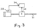
- a current consumption sensor in the supply line to detect an emergency operation of the driving electric motor is arranged.
- the helical groove creates a sufficiently large flow through the Radial and axial bearings through with little design effort. It is preferably proposed that a helical groove on each Ends of the bearing housing is arranged in the respective gap.
- the centrifugal pump 1 with magnetic coupling has one in a pump chamber rotating impeller 2, which is fixed on one end of a shaft 3.
- the Shaft 3 carries a shaft sleeve 12, which by two ceramic radial bearings 4, 5 and two ceramic thrust bearings 6, 7 is mounted on the inner wall of a tubular bearing housing 8 are attached.
- the bearing housing 8 is on the Wall 11 attached to the pump chamber 9 from the interior of a Separates can 10, which is attached to the partition 11.
- At that End of the pump impeller 2 facing away from the shaft 3 carries an inner Pot-shaped magnetic rotor 14.
- the fastening means 15 on the shaft 3 a circular base 16 is formed, on the outer edge of a tubular cylindrical coaxial magnetic carrier 17 is formed on the outside of which the output magnets 18 are attached.
- the bearing housing 8 thus extends coaxially in the magnet rotor 14, wherein an annular space 19 and between the magnetic carrier 17 and the bearing housing 8 there is an annular gap 20 between the magnet carrier 17 and the containment shell 10.
- the containment shell 10 is surrounded by a drive pot, not shown, which carries the drive magnets inside and via a coaxial shaft from one Electric motor is driven.
- a ring-shaped coaxial Flow channel (annular space) 21 is introduced, which is at the level of the annular space 19 and is crossed by two to four radial axial blades 22 which the Hold magnet carrier 17 on floor 16.
- the blades are regular Distances (angles) formed on the floor and magnetic carrier and have one Angle of attack from 5 to 15 degrees.
- the preferably three blades 22 promote through the inlet channels 23 in the Liquid entering the interior of the canned tube from the annular gap 20 into the Gap 24 between the bearing housing 8 and shaft sleeve 12, so that the fluid conveyed thereby through the radial and axial bearings 4 to 7 flows through and then flows back to the pump chamber.
- the tubular bearing housing 8 forms on the side facing away from the impeller 2 end face an annular gap 25 with an inner region of the inner Magnet rotor or the fastener 15.
- an annular gap 25 with an inner region of the inner Magnet rotor or the fastener 15.
- the outside of the ring 26 forms with the inside of the Bearing housing 8 the annular gap 25, the radial width B1 is less than that radial width B2 of the annular gap 20.
- a helical coaxial groove 27 which in the gap 25 promotes the liquid to room 24.
- the groove 27 can also be arranged in the outer wall of the magnetic rotor or the ring 26.
Landscapes
- Engineering & Computer Science (AREA)
- Mechanical Engineering (AREA)
- General Engineering & Computer Science (AREA)
- Physics & Mathematics (AREA)
- Fluid Mechanics (AREA)
- Chemical & Material Sciences (AREA)
- Ceramic Engineering (AREA)
- Structures Of Non-Positive Displacement Pumps (AREA)
Abstract
Description
- Fig. 1
- einen axialen Schnitt durch den inneren Bereich einer Magnetkupplungskreiselpumpe,
- Fig. 2
- einen vergrößerten Ausschnitt aus Fig. 1,
- Fig. 3
- ein Schaltbild der Sensoren.
Claims (5)
- Kreiselpumpe mit einer zwischen Pumpenwelle und Antriebswelle angeordneten Magnetkupplung und mit einem Spalttopf (10) im Magnetspalt zwischen dem inneren Magnetrotor (14) der Pumpe und dem äußeren Magnetrotor der Antriebswelle, wobei im Inneren des von der Förderflüssigkeit durchflossenen Spalttopfes (10) der innere Magnetrotor (14) an einem rohrförmigen Lagergehäuse (8) gelagert ist, das die Pumpenlaufradwelle (3) umgibt, die auf der dem Pumpenlaufrad (2) abgewandten Seite Befestigungsmittel (15) für den inneren Magnetrotor (14) besitzt, der zwischen dem Lagergehäuse (8) und dem Spalttopf (10) angeordnet ist, dadurch gekennzeichnet,dass der Ringspalt (25) zwischen dem Lagerbereich des inneren Magnetrotors (14) und der Innenwand des rohrförmigen Lagergehäuses (8) in seiner radialen Breite (B1) kleiner ist als der Ringspalt (20) zwischen dem inneren Magnetrotor (14) und dem Spaltrohr (10).
- Kreiselpumpe nach Anspruch 1,dadurch gekennzeichnet, dass zum Erkennen eines Notlaufs nahe der Lager (4 - 7) des inneren Magnetrotors (14) mindestens ein Temperatursensor (28) angeordnet ist.
- Kreiselpumpe nach Anspruch 1 oder 2, dadurch gekennzeichnet, dass zum Erkennen eines Notlaufs ein Stromaufnahmesensor (29) in der Zuleitung (30) des antreibenden Elektromotors angeordnet ist.
- Kreiselpumpe mit einer zwischen Pumpenwelle und Antriebswelle angeordneten Magnetkupplung und mit einem Spalttopf (10) im Magnetspalt zwischen dem inneren Magnetrotor (14) der Pumpe und dem äußeren Magnetrotor der Antriebswelle, wobei im Inneren des von der Förderflüssigkeit durchflossenen Spalttopfes (10) der innere Magnetrotor (14) an einem rohrförmigen Lagergehäuse (8) gelagert ist, das die Pumpenlaufradwelle (3) umgibt, die auf der dem Pumpenlaufrad (2) abgewandten Seite Befestigungsmittel (15) für den inneren Magnetrotor (14) besitzt, der zwischen dem Lagergehäuse (8) und dem Spalttopf (10) angeordnet ist insbesondere nach Anspruch 1, 2 oder 3, dadurch gekennzeichnet, dass im Ringspalt (25) zwischen dem Lagerbereich des inneren Magnetrotors und der Innenwand des rohrförmigen Lagergehäuses (8) eine schraubenförmige Nut (27) in der Innenwand des rohrförmigen Lagergehäuses (8) und/oder in der Außenwand des Magnetrotorlagers (26) angeordnet ist, die die Flüssigkeit durch die Lager (4 - 7) fördert, die zwischen dem Lagergehäuse (8) und der Welle (3) oder der Wellenhülse (12) angeordnet sind.
- Kreiselpumpe nach Anspruch 4, dadurch gekennzeichnet, dass je eine schraubenförmige Nut an beiden Enden des Lagergehäuses (8) im jeweiligen Spalt (25) angeordnet ist.
Priority Applications (1)
| Application Number | Priority Date | Filing Date | Title |
|---|---|---|---|
| EP06015105A EP1719914B1 (de) | 2000-05-22 | 2001-04-03 | Kreiselpumpe mit Magnetkupplung |
Applications Claiming Priority (2)
| Application Number | Priority Date | Filing Date | Title |
|---|---|---|---|
| DE10024953A DE10024953A1 (de) | 2000-05-22 | 2000-05-22 | Kreiselpumpe mit Magnetkupplung |
| DE10024953 | 2000-05-22 |
Related Child Applications (1)
| Application Number | Title | Priority Date | Filing Date |
|---|---|---|---|
| EP06015105A Division EP1719914B1 (de) | 2000-05-22 | 2001-04-03 | Kreiselpumpe mit Magnetkupplung |
Publications (3)
| Publication Number | Publication Date |
|---|---|
| EP1158174A2 true EP1158174A2 (de) | 2001-11-28 |
| EP1158174A3 EP1158174A3 (de) | 2005-09-07 |
| EP1158174B1 EP1158174B1 (de) | 2007-03-14 |
Family
ID=7642885
Family Applications (2)
| Application Number | Title | Priority Date | Filing Date |
|---|---|---|---|
| EP01108334A Expired - Lifetime EP1158174B1 (de) | 2000-05-22 | 2001-04-03 | Kreiselpumpe mit Magnetkupplung |
| EP06015105A Expired - Lifetime EP1719914B1 (de) | 2000-05-22 | 2001-04-03 | Kreiselpumpe mit Magnetkupplung |
Family Applications After (1)
| Application Number | Title | Priority Date | Filing Date |
|---|---|---|---|
| EP06015105A Expired - Lifetime EP1719914B1 (de) | 2000-05-22 | 2001-04-03 | Kreiselpumpe mit Magnetkupplung |
Country Status (4)
| Country | Link |
|---|---|
| US (1) | US6554576B2 (de) |
| EP (2) | EP1158174B1 (de) |
| AT (2) | ATE356937T1 (de) |
| DE (3) | DE10024953A1 (de) |
Families Citing this family (22)
| Publication number | Priority date | Publication date | Assignee | Title |
|---|---|---|---|---|
| US8337166B2 (en) * | 2001-11-26 | 2012-12-25 | Shurflo, Llc | Pump and pump control circuit apparatus and method |
| DE10221843B4 (de) * | 2002-05-16 | 2004-12-30 | Minebea Co., Ltd. | Elektromotor zur Verwendung als Pumpenmotor und Pumpe |
| RU2374501C1 (ru) * | 2008-06-04 | 2009-11-27 | Государственное образовательное учреждение высшего профессионального образования "Южно-Российский государственный технический университет (Новочеркасский политехнический институт)" | Разгрузочное устройство центробежного секционного насоса |
| RU2374500C1 (ru) * | 2008-06-04 | 2009-11-27 | Государственное образовательное учреждение высшего профессионального образования "Южно-Российский государственный технический университет (Новочеркасский политехнический институт)" | Разгрузочное устройство центробежного многоступенчатого насоса |
| RU2374502C1 (ru) * | 2008-06-04 | 2009-11-27 | Государственное образовательное учреждение высшего профессионального образования "Южно-Российский государственный технический университет (Новочеркасский политехнический институт)" | Разгрузочное устройство центробежного насоса |
| JP2013502532A (ja) * | 2009-08-19 | 2013-01-24 | ホフマン エンクロージャーズ インコーポレイテッド ディー/ビー/エー ペンテアー テクニカル プロダクツ | 組込型モータを用いた磁気駆動ポンプ組立体 |
| DE102009052856B3 (de) * | 2009-11-11 | 2010-09-09 | Leistritz Ag | Pumpe mit einer Magnetkupplung |
| WO2011122556A1 (ja) * | 2010-03-29 | 2011-10-06 | Ntn株式会社 | 流体動圧軸受装置およびその組立方法 |
| CN102465884A (zh) * | 2010-11-17 | 2012-05-23 | 黄佳华 | 一种立式磁力驱动料浆泵 |
| DE102011114191A1 (de) | 2011-09-22 | 2013-03-28 | Eagleburgmann Germany Gmbh & Co. Kg | Spalttopf für eine Magnetkupplung mit verbesserter Fluidströmung |
| TW201317459A (zh) * | 2011-10-26 | 2013-05-01 | 協磁股份有限公司 | 永磁罐裝泵結構改良 |
| US20140271270A1 (en) * | 2013-03-12 | 2014-09-18 | Geotek Energy, Llc | Magnetically coupled expander pump with axial flow path |
| DE102014006568A1 (de) * | 2013-05-08 | 2014-11-13 | Ksb Aktiengesellschaft | Pumpenanordnung und Verfahren zum Herstellen eines Spalttopfes der Pumpenanordnung |
| DE102013007849A1 (de) * | 2013-05-08 | 2014-11-13 | Ksb Aktiengesellschaft | Pumpenanordnung |
| CN103410739B (zh) * | 2013-07-24 | 2016-09-21 | 黄佳华 | 立式液下多组渣浆磁力泵 |
| CN104776033B (zh) * | 2014-01-14 | 2017-09-15 | 高涵文 | 一种耐腐蚀抗干磨的磁力泵 |
| US9771938B2 (en) | 2014-03-11 | 2017-09-26 | Peopleflo Manufacturing, Inc. | Rotary device having a radial magnetic coupling |
| US9920764B2 (en) | 2015-09-30 | 2018-03-20 | Peopleflo Manufacturing, Inc. | Pump devices |
| CN110873061B (zh) * | 2018-08-29 | 2023-08-01 | 广东德昌电机有限公司 | 泵体及用于泵体的转子组件的制造方法 |
| DE202019101723U1 (de) * | 2019-03-26 | 2020-06-29 | Meßner GmbH & Co. KG | Teichpumpe |
| KR102484602B1 (ko) * | 2020-11-23 | 2023-01-06 | 주식회사 코아비스 | 전동식 워터 펌프 |
| DE102020132907A1 (de) | 2020-12-10 | 2022-06-15 | Eagleburgmann Germany Gmbh & Co. Kg | Magnetkupplung mit verbesserter Kühlung |
Family Cites Families (14)
| Publication number | Priority date | Publication date | Assignee | Title |
|---|---|---|---|---|
| GB922319A (en) * | 1960-03-28 | 1963-03-27 | Klaus Franz | Centrifugal pump |
| US3420184A (en) * | 1967-05-17 | 1969-01-07 | Julius L Englesberg | Pump employing magnetic drive |
| DE2639540A1 (de) * | 1976-09-02 | 1978-03-09 | Grundfos As | Gleitlagerhuelse fuer die pumpenwelle von umwaelzpumpen fuer heizungs- und brauchwasseranlagen |
| DE2752249B2 (de) * | 1977-11-23 | 1979-09-27 | Klein, Schanzlin & Becker Ag, 6710 Frankenthal | Schutzeinrichtung für Pumpen |
| JPS6352992U (de) * | 1986-09-25 | 1988-04-09 | ||
| DE3704671A1 (de) * | 1987-02-14 | 1988-08-25 | Richter Chemie Technik Gmbh | Leckanzeigevorrichtung fuer eine magnetkreiselpumpe |
| DE3715484A1 (de) * | 1987-05-09 | 1988-11-17 | Klaus Union Armaturen | Magnetischer pumpenantrieb |
| EP0308372B1 (de) * | 1987-09-15 | 1991-04-03 | Bieri Pumpenbau Ag | Umwälzpumpe insbesondere für Warmwasseranlagen |
| DE8906020U1 (de) * | 1989-05-13 | 1989-06-29 | Rheinhütte GmbH & Co., 6200 Wiesbaden | Magnetkupplungspumpe |
| EP0431332B1 (de) * | 1989-11-08 | 1995-11-02 | Sanwa Tokushu Seiko Co., Ltd. | Magnetisch angetriebene Pumpe |
| US5184945A (en) * | 1991-12-27 | 1993-02-09 | Assoma, Inc. | Bushing structure for using in magnetically driving centrifugal pumps |
| DE4212982C2 (de) * | 1992-04-18 | 1996-04-11 | Lederle Pumpen & Maschf | Pumpe für heiße Fördermedien |
| DE9316897U1 (de) * | 1993-11-04 | 1994-07-28 | Renner GmbH, 75433 Maulbronn | Magnetpumpe mit Heißlaufschutz |
| US5944489A (en) * | 1996-12-11 | 1999-08-31 | Crane Co. | Rotary fluid pump |
-
2000
- 2000-05-22 DE DE10024953A patent/DE10024953A1/de not_active Withdrawn
-
2001
- 2001-04-03 AT AT01108334T patent/ATE356937T1/de active
- 2001-04-03 EP EP01108334A patent/EP1158174B1/de not_active Expired - Lifetime
- 2001-04-03 DE DE50112181T patent/DE50112181D1/de not_active Expired - Lifetime
- 2001-04-03 AT AT06015105T patent/ATE486219T1/de active
- 2001-04-03 DE DE50115684T patent/DE50115684D1/de not_active Expired - Lifetime
- 2001-04-03 EP EP06015105A patent/EP1719914B1/de not_active Expired - Lifetime
- 2001-05-22 US US09/862,526 patent/US6554576B2/en not_active Expired - Lifetime
Also Published As
| Publication number | Publication date |
|---|---|
| EP1158174A3 (de) | 2005-09-07 |
| ATE486219T1 (de) | 2010-11-15 |
| EP1158174B1 (de) | 2007-03-14 |
| DE10024953A1 (de) | 2001-11-29 |
| ATE356937T1 (de) | 2007-04-15 |
| DE50115684D1 (de) | 2010-12-09 |
| EP1719914A3 (de) | 2006-11-15 |
| EP1719914A2 (de) | 2006-11-08 |
| US6554576B2 (en) | 2003-04-29 |
| DE50112181D1 (de) | 2007-04-26 |
| US20010043865A1 (en) | 2001-11-22 |
| EP1719914B1 (de) | 2010-10-27 |
Similar Documents
| Publication | Publication Date | Title |
|---|---|---|
| EP1158174B1 (de) | Kreiselpumpe mit Magnetkupplung | |
| CH668101A5 (de) | Magnetisch angetriebene zentrifugalpumpe. | |
| EP1158173B1 (de) | Kreiselpumpe mit Magnetkupplung | |
| DE69223216T2 (de) | Laufrad für Kreiselpumpen | |
| DE69124498T2 (de) | Flüsskeitsringpumpe mit Ringtrommeln und Umfangwänden | |
| DE2254265A1 (de) | Stopfbuechslose chemiekreiselpumpe | |
| EP2994643B1 (de) | Pumpenanordnung und verfahren zum herstellen eines spalttopfes der pumpenanordnung | |
| DE2645305C3 (de) | Flüssigkeitsring-Verdichter | |
| DE69614490T2 (de) | Gebläse für gaslaser | |
| DE7507522U (de) | Kreiselpumpe | |
| DE2711847B1 (de) | Roentgenroehre | |
| DE2550844B2 (de) | Laufrad | |
| DE3637501C2 (de) | Axialschubkompensation für Zentrifugalpumpen | |
| EP0629780A1 (de) | Tauchmotorpumpe | |
| DE102007020218A1 (de) | Förderpumpe | |
| WO2011157485A1 (de) | Doppelflutige kreiselpumpe | |
| DE3007187A1 (de) | Zentrifugalpumpe | |
| DE2460748B2 (de) | Umwaelzpumpe fuer insbesondere heizungs- und brauchwasseranlagen | |
| DE10062451A1 (de) | Förderpumpe | |
| EP0599204A1 (de) | Tauchpumpenaggregat | |
| EP0677661B1 (de) | Zentrifugalpumpe | |
| DE3509023C2 (de) | ||
| DE9116052U1 (de) | Pumpe für Flüssigkeiten niedriger Viskosität oder nahe dem Siedepunkt | |
| EP1178214B1 (de) | Kreiselpumpe | |
| DE69107330T2 (de) | Geräuscharme Kreiselmotorpumpe für Flüssigkeiten. |
Legal Events
| Date | Code | Title | Description |
|---|---|---|---|
| PUAI | Public reference made under article 153(3) epc to a published international application that has entered the european phase |
Free format text: ORIGINAL CODE: 0009012 |
|
| AK | Designated contracting states |
Kind code of ref document: A2 Designated state(s): AT BE CH CY DE DK ES FI FR GB GR IE IT LI LU MC NL PT SE TR |
|
| AX | Request for extension of the european patent |
Free format text: AL;LT;LV;MK;RO;SI |
|
| RIC1 | Information provided on ipc code assigned before grant |
Ipc: 7F 04D 13/06 B Ipc: 7F 04D 29/04 B Ipc: 7F 04D 13/02 A |
|
| PUAL | Search report despatched |
Free format text: ORIGINAL CODE: 0009013 |
|
| 17P | Request for examination filed |
Effective date: 20050616 |
|
| AK | Designated contracting states |
Kind code of ref document: A3 Designated state(s): AT BE CH CY DE DK ES FI FR GB GR IE IT LI LU MC NL PT SE TR |
|
| AX | Request for extension of the european patent |
Extension state: AL LT LV MK RO SI |
|
| RAP1 | Party data changed (applicant data changed or rights of an application transferred) |
Owner name: ITT MANUFACTURING ENTERPRISES, INC. |
|
| AKX | Designation fees paid |
Designated state(s): AT BE CH CY DE DK ES FI FR GB GR IE IT LI LU MC NL PT SE TR |
|
| GRAP | Despatch of communication of intention to grant a patent |
Free format text: ORIGINAL CODE: EPIDOSNIGR1 |
|
| GRAS | Grant fee paid |
Free format text: ORIGINAL CODE: EPIDOSNIGR3 |
|
| GRAA | (expected) grant |
Free format text: ORIGINAL CODE: 0009210 |
|
| AK | Designated contracting states |
Kind code of ref document: B1 Designated state(s): AT BE CH CY DE DK ES FI FR GB GR IE IT LI LU MC NL PT SE TR |
|
| PG25 | Lapsed in a contracting state [announced via postgrant information from national office to epo] |
Ref country code: FI Free format text: LAPSE BECAUSE OF FAILURE TO SUBMIT A TRANSLATION OF THE DESCRIPTION OR TO PAY THE FEE WITHIN THE PRESCRIBED TIME-LIMIT Effective date: 20070314 |
|
| REG | Reference to a national code |
Ref country code: GB Ref legal event code: FG4D Free format text: NOT ENGLISH |
|
| REG | Reference to a national code |
Ref country code: CH Ref legal event code: NV Representative=s name: SCHMAUDER & PARTNER AG PATENTANWALTSBUERO Ref country code: CH Ref legal event code: EP |
|
| REF | Corresponds to: |
Ref document number: 50112181 Country of ref document: DE Date of ref document: 20070426 Kind code of ref document: P |
|
| REG | Reference to a national code |
Ref country code: IE Ref legal event code: FG4D Free format text: LANGUAGE OF EP DOCUMENT: GERMAN |
|
| PG25 | Lapsed in a contracting state [announced via postgrant information from national office to epo] |
Ref country code: SE Free format text: LAPSE BECAUSE OF FAILURE TO SUBMIT A TRANSLATION OF THE DESCRIPTION OR TO PAY THE FEE WITHIN THE PRESCRIBED TIME-LIMIT Effective date: 20070614 |
|
| PG25 | Lapsed in a contracting state [announced via postgrant information from national office to epo] |
Ref country code: ES Free format text: LAPSE BECAUSE OF FAILURE TO SUBMIT A TRANSLATION OF THE DESCRIPTION OR TO PAY THE FEE WITHIN THE PRESCRIBED TIME-LIMIT Effective date: 20070625 |
|
| PG25 | Lapsed in a contracting state [announced via postgrant information from national office to epo] |
Ref country code: PT Free format text: LAPSE BECAUSE OF FAILURE TO SUBMIT A TRANSLATION OF THE DESCRIPTION OR TO PAY THE FEE WITHIN THE PRESCRIBED TIME-LIMIT Effective date: 20070814 |
|
| ET | Fr: translation filed | ||
| REG | Reference to a national code |
Ref country code: IE Ref legal event code: FD4D |
|
| PLBE | No opposition filed within time limit |
Free format text: ORIGINAL CODE: 0009261 |
|
| STAA | Information on the status of an ep patent application or granted ep patent |
Free format text: STATUS: NO OPPOSITION FILED WITHIN TIME LIMIT |
|
| PG25 | Lapsed in a contracting state [announced via postgrant information from national office to epo] |
Ref country code: IE Free format text: LAPSE BECAUSE OF FAILURE TO SUBMIT A TRANSLATION OF THE DESCRIPTION OR TO PAY THE FEE WITHIN THE PRESCRIBED TIME-LIMIT Effective date: 20070314 Ref country code: DK Free format text: LAPSE BECAUSE OF FAILURE TO SUBMIT A TRANSLATION OF THE DESCRIPTION OR TO PAY THE FEE WITHIN THE PRESCRIBED TIME-LIMIT Effective date: 20070314 |
|
| 26N | No opposition filed |
Effective date: 20071217 |
|
| PG25 | Lapsed in a contracting state [announced via postgrant information from national office to epo] |
Ref country code: GR Free format text: LAPSE BECAUSE OF FAILURE TO SUBMIT A TRANSLATION OF THE DESCRIPTION OR TO PAY THE FEE WITHIN THE PRESCRIBED TIME-LIMIT Effective date: 20070615 |
|
| PG25 | Lapsed in a contracting state [announced via postgrant information from national office to epo] |
Ref country code: MC Free format text: LAPSE BECAUSE OF NON-PAYMENT OF DUE FEES Effective date: 20070430 |
|
| PG25 | Lapsed in a contracting state [announced via postgrant information from national office to epo] |
Ref country code: CY Free format text: LAPSE BECAUSE OF FAILURE TO SUBMIT A TRANSLATION OF THE DESCRIPTION OR TO PAY THE FEE WITHIN THE PRESCRIBED TIME-LIMIT Effective date: 20070314 |
|
| REG | Reference to a national code |
Ref country code: CH Ref legal event code: PCAR Free format text: SCHMAUDER & PARTNER AG PATENT- UND MARKENANWAELTE VSP;ZWAENGIWEG 7;8038 ZUERICH (CH) |
|
| PG25 | Lapsed in a contracting state [announced via postgrant information from national office to epo] |
Ref country code: LU Free format text: LAPSE BECAUSE OF NON-PAYMENT OF DUE FEES Effective date: 20070403 |
|
| PG25 | Lapsed in a contracting state [announced via postgrant information from national office to epo] |
Ref country code: TR Free format text: LAPSE BECAUSE OF FAILURE TO SUBMIT A TRANSLATION OF THE DESCRIPTION OR TO PAY THE FEE WITHIN THE PRESCRIBED TIME-LIMIT Effective date: 20070314 |
|
| PGFP | Annual fee paid to national office [announced via postgrant information from national office to epo] |
Ref country code: IT Payment date: 20120423 Year of fee payment: 12 |
|
| PG25 | Lapsed in a contracting state [announced via postgrant information from national office to epo] |
Ref country code: IT Free format text: LAPSE BECAUSE OF NON-PAYMENT OF DUE FEES Effective date: 20130403 |
|
| REG | Reference to a national code |
Ref country code: FR Ref legal event code: PLFP Year of fee payment: 15 |
|
| REG | Reference to a national code |
Ref country code: FR Ref legal event code: PLFP Year of fee payment: 16 |
|
| REG | Reference to a national code |
Ref country code: FR Ref legal event code: PLFP Year of fee payment: 17 |
|
| PGFP | Annual fee paid to national office [announced via postgrant information from national office to epo] |
Ref country code: FR Payment date: 20170426 Year of fee payment: 17 Ref country code: CH Payment date: 20170427 Year of fee payment: 17 Ref country code: GB Payment date: 20170427 Year of fee payment: 17 |
|
| PGFP | Annual fee paid to national office [announced via postgrant information from national office to epo] |
Ref country code: BE Payment date: 20170427 Year of fee payment: 17 |
|
| REG | Reference to a national code |
Ref country code: CH Ref legal event code: PL |
|
| REG | Reference to a national code |
Ref country code: BE Ref legal event code: MM Effective date: 20180430 |
|
| GBPC | Gb: european patent ceased through non-payment of renewal fee |
Effective date: 20180403 |
|
| PG25 | Lapsed in a contracting state [announced via postgrant information from national office to epo] |
Ref country code: GB Free format text: LAPSE BECAUSE OF NON-PAYMENT OF DUE FEES Effective date: 20180403 Ref country code: BE Free format text: LAPSE BECAUSE OF NON-PAYMENT OF DUE FEES Effective date: 20180430 Ref country code: CH Free format text: LAPSE BECAUSE OF NON-PAYMENT OF DUE FEES Effective date: 20180430 Ref country code: LI Free format text: LAPSE BECAUSE OF NON-PAYMENT OF DUE FEES Effective date: 20180430 |
|
| PG25 | Lapsed in a contracting state [announced via postgrant information from national office to epo] |
Ref country code: FR Free format text: LAPSE BECAUSE OF NON-PAYMENT OF DUE FEES Effective date: 20180430 |
|
| PGFP | Annual fee paid to national office [announced via postgrant information from national office to epo] |
Ref country code: DE Payment date: 20200429 Year of fee payment: 20 Ref country code: NL Payment date: 20200426 Year of fee payment: 20 |
|
| PGFP | Annual fee paid to national office [announced via postgrant information from national office to epo] |
Ref country code: AT Payment date: 20200319 Year of fee payment: 20 |
|
| REG | Reference to a national code |
Ref country code: DE Ref legal event code: R071 Ref document number: 50112181 Country of ref document: DE |
|
| REG | Reference to a national code |
Ref country code: NL Ref legal event code: MK Effective date: 20210402 |
|
| REG | Reference to a national code |
Ref country code: AT Ref legal event code: MK07 Ref document number: 356937 Country of ref document: AT Kind code of ref document: T Effective date: 20210403 |