EP1151886A2 - Lagerung einer Motor-Getriebeeinheit - Google Patents
Lagerung einer Motor-Getriebeeinheit Download PDFInfo
- Publication number
- EP1151886A2 EP1151886A2 EP01103444A EP01103444A EP1151886A2 EP 1151886 A2 EP1151886 A2 EP 1151886A2 EP 01103444 A EP01103444 A EP 01103444A EP 01103444 A EP01103444 A EP 01103444A EP 1151886 A2 EP1151886 A2 EP 1151886A2
- Authority
- EP
- European Patent Office
- Prior art keywords
- bearing element
- chamber
- motor
- bearing
- storage according
- Prior art date
- Legal status (The legal status is an assumption and is not a legal conclusion. Google has not performed a legal analysis and makes no representation as to the accuracy of the status listed.)
- Granted
Links
Images


Classifications
-
- B—PERFORMING OPERATIONS; TRANSPORTING
- B60—VEHICLES IN GENERAL
- B60K—ARRANGEMENT OR MOUNTING OF PROPULSION UNITS OR OF TRANSMISSIONS IN VEHICLES; ARRANGEMENT OR MOUNTING OF PLURAL DIVERSE PRIME-MOVERS IN VEHICLES; AUXILIARY DRIVES FOR VEHICLES; INSTRUMENTATION OR DASHBOARDS FOR VEHICLES; ARRANGEMENTS IN CONNECTION WITH COOLING, AIR INTAKE, GAS EXHAUST OR FUEL SUPPLY OF PROPULSION UNITS IN VEHICLES
- B60K5/00—Arrangement or mounting of internal-combustion or jet-propulsion units
- B60K5/12—Arrangement of engine supports
- B60K5/1208—Resilient supports
- B60K5/1216—Resilient supports characterised by the location of the supports relative to the motor or to each other
-
- B—PERFORMING OPERATIONS; TRANSPORTING
- B60—VEHICLES IN GENERAL
- B60K—ARRANGEMENT OR MOUNTING OF PROPULSION UNITS OR OF TRANSMISSIONS IN VEHICLES; ARRANGEMENT OR MOUNTING OF PLURAL DIVERSE PRIME-MOVERS IN VEHICLES; AUXILIARY DRIVES FOR VEHICLES; INSTRUMENTATION OR DASHBOARDS FOR VEHICLES; ARRANGEMENTS IN CONNECTION WITH COOLING, AIR INTAKE, GAS EXHAUST OR FUEL SUPPLY OF PROPULSION UNITS IN VEHICLES
- B60K5/00—Arrangement or mounting of internal-combustion or jet-propulsion units
- B60K5/12—Arrangement of engine supports
- B60K5/1208—Resilient supports
- B60K5/1225—Resilient supports comprising resilient rings surrounding a part of the unit
Definitions
- this object is achieved in that the second bearing element is designed in such a way and without moving Intermediate element arranged on the engine or transmission and vehicle body is that moment forces supported by the second bearing element Motor gear unit in the vehicle longitudinal direction in the Vehicle body are initiated, and that the second bearing element in a first area, which has small deflections in the vehicle longitudinal direction around the static rest position when the engine is at a standstill, a first Spring rate and in a second area, which adjoins the first area connects and includes larger deflections in the vehicle longitudinal direction, a has a second spring rate, the second spring rate being greater than the first Spring rate is.
- the second bearing element is a first anchoring part and has a movable relative to this second anchoring part, wherein at least one between the first and the second anchoring part Spring body works.
- the bearing element can be attached to the anchoring parts on the one hand with motor or gearbox and on the other hand with the Vehicle body without movable intermediate elements, such as pendulum supports, get connected.
- Embodiment of the invention provides that the motor-gear unit with exactly three bearing elements on the vehicle body is.
- the first, second and third bearing element according to the invention are in the in most cases sufficient to be a good one in terms of vibration To achieve storage of the transversely installed motor-gear unit.
- it does not lead out of the present invention if in addition to the arranged and executed three bearing elements according to the invention or more additional bearing elements should be provided.
- the motor gear unit 4 consists essentially of the transversely installed Motor 5 and the gear 6.
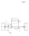
- the bearing of the motor gear unit 4 has a first bearing element 1, which between the engine 5 and the vehicle body is arranged, a second bearing element 2, which between the motor 5 and Vehicle body is arranged and a third bearing element 3, which is arranged between the transmission 6 and the vehicle body. How 2, the second bearing element 2 is below of the first bearing element 1 arranged.
- the second bearing element is 2 provided substantially vertically under the first bearing element 1.
- the first bearing element 1 is above the torque roll axis 7 to the motor 5 arranged.
- the third bearing element 3 is adjacent to the torque roll axis 7 or arranged on the torque roll axis 7 itself.
- the second bearing element 2 is designed in this way and has no movable Intermediate element arranged on the engine and vehicle body that through the second bearing element 2 supported moment forces of the motor-gear unit 4 essentially in the longitudinal direction of the vehicle, ie in or against the Direction X, are introduced into the vehicle body.
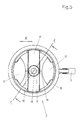
- the second spring bodies 14, 14 ' are in between the second Anchoring part 10 and the first spring body 11 formed cavity arranged. Like the first spring body 11, they consist of elastomer and are produced with this in a single process step. How 6, a second spring body 14, 14 ' on both sides, in particular symmetrically to the first plane 15 in one second level 16, which is essentially perpendicular to the first level 15 extends, arranged. It is between the second spring body 14 and 14 ' and the first spring body 11 each have a gap 16, 16 '. By this gap 16, 16 'is achieved that with deflections which are smaller than the gap 16, 16 'are the spring rate of the second bearing element 2 in is essentially determined solely by the first spring body 11. If the deflections exceed the size of the gap 16, 16 ' second spring body 14, 14 'moves or deforms, so that their Spring rates added to the spring rate of the first spring body.
- the first and / or the second chamber wall 17, 19 are arranged in this way and designed so that with a relative movement of the first and second Anchoring part 9, 10 in the area of small deflections around the static
- the rest of the engine 5 is not the volume of the first chamber 18 is changed. This is achieved through the gap 16, 16 'mentioned above, which between the chamber walls 17 and 19 and the first spring body 11 is formed.
- the volume of the first chamber 18 is changed. In this way, Range of larger deflections a hydraulic damping between first and second anchoring part occurring relative movements.
- Figures 9 and 10 is a first embodiment of a hydraulic damping bearing 24 described, which according to the invention first Bearing element 1 and / or third bearing element 3 can be used.
- the bearing 24 has a first support body 25 and a movable one this arranged second support body 26. About those made of metal existing first and second support body 25, 26, the bearing on the one hand with the motor 5 or the gear 6 and on the other hand with the Vehicle body to be connected.
- the Stop 37 not the vibration behavior of the bearing 24. Will the However, amplitudes of the movements are larger, then the buffer 38 comes in Contact with the second housing section 36 and is deformed in the process. How In FIG. 9, the buffer 38 is different in the x and y directions formed thick, so that different soft in these directions Attacks are generated. In the embodiment shown in Figure 9 the buffer 38 is thicker than the buffer 38 ', which makes it softer in the x direction Stop is achieved as in the y direction.
- the bearing 39 has a first support body 25 and one relative to that first support body 25 movable second support body 26.
- the second Support body 26 surrounds the first support body 25 in a ring shape. It is a spring element 27 between the first and second support bodies 25, 26 provided which is designed as a rubber body.
- a work space 30 and Compensation room 31 is formed in the between the first and second support body 25, 26 formed space.
- the work space 30 is by the Limited spring element 27 and the second support body 26.
- the Compensation chamber 31 is formed by the second support body 26 and an elastic one Wall 40 limited.
- the work space 30 and the compensation space 31 are filled with damping fluid and via a damping channel 34 connected to each other in a liquid-conducting manner.
- the bearing 39 has a rebound stop acting transversely to the bearing axis 41 on. It is formed by an elastic buffer attached to the second support body 26 is formed.
- the rebound stop 41 is of that first support body 25 separated by a gap 42. At that Rebound stop 41 is opposite side of the first support body 25 also applied an elastic layer.
- the second one Support body 26 a radially inwardly facing third housing section 43 which has a stop surface for a on the first support body 25 trained axial stop 44 forms.
- the in the vehicle transverse direction acting axial stop 44 is through a gap 45 from the third Housing section 43 removed.
- the axial stop 44 is also with provided with an elastic buffer made of elastomer.
- the first support body 25 is also transverse to the bearing axis 29 and offset to the rebound stop 41 arranged torque support buffers 46 provided.
- the torque support buffer prevents this Generation of noises, which otherwise occur when touching first and second support bodies 25, 26 could arise.
Landscapes
- Engineering & Computer Science (AREA)
- Chemical & Material Sciences (AREA)
- Combustion & Propulsion (AREA)
- Transportation (AREA)
- Mechanical Engineering (AREA)
- Arrangement Or Mounting Of Propulsion Units For Vehicles (AREA)
- Vibration Prevention Devices (AREA)
- Combined Devices Of Dampers And Springs (AREA)
- Support Of The Bearing (AREA)
Abstract
Description
- Figur 1
- eine erfindungsgemäße Motorlagerung von oben
- Figur 2
- eine erfindungsgemäße Motorlagerung von der Rückseite
- Figur 3
- ein Lagerelement, welches insbesondere als zweites Lagerelement verwendet wird in dreidimensionaler Darstellung
- Figur 4
- das Lagerelement aus Figur 3 von oben
- Figur 5
- das Lagerelement aus Figur 3 von vorn
- Figur 6
- das Lagerelement aus Figur 3 im Schnitt entlang der Linie A-A
- Figur 7
- das Lagerelement aus Figur 4 im Schnitt entlang der Linie B-B
- Figur 8
- das Lagerelement aus Figur 5 im Schnitt entlang der Linie C-C
- Figur 9
- ein Lagerelement, welches erfindungsgemäß als erstes und/oder drittes Lagerelement verwendet wird, im Schnitt
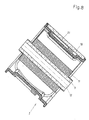
- Figur 10
- eine weitere Ausführungsform eines Lagerelements welches erfindungsgemäß als erstes und/oder drittes Lagerelement verwendet wird, im Schnitt
- Figur 11
- das Lagerelement aus Figur 10 im Schnitt entlang der Linie D-D
Der die erste und zweite Kammer 18, 20 verbindende Durchlaß 21 erstreckt sich in Umfangsrichtung im Inneren des zweiten Verankerungsteils 10. Dabei ist der Durchlaß 21 benachbart zur Außenwandung 23 angeordnet. In dem Durchlaß 21 ist ein Drosselventil angeordnet, durch welches der Strömungswiderstand in dem Durchlaß 21 auf einen gewünschten Wert eingestellt werden kann.
Claims (14)
Applications Claiming Priority (2)
| Application Number | Priority Date | Filing Date | Title |
|---|---|---|---|
| DE10016654A DE10016654B4 (de) | 2000-04-04 | 2000-04-04 | Lagerung einer Motor-Getriebeeinheit |
| DE10016654 | 2000-04-04 |
Publications (3)
| Publication Number | Publication Date |
|---|---|
| EP1151886A2 true EP1151886A2 (de) | 2001-11-07 |
| EP1151886A3 EP1151886A3 (de) | 2003-06-11 |
| EP1151886B1 EP1151886B1 (de) | 2005-06-01 |
Family
ID=7637506
Family Applications (1)
| Application Number | Title | Priority Date | Filing Date |
|---|---|---|---|
| EP01103444A Expired - Lifetime EP1151886B1 (de) | 2000-04-04 | 2001-02-14 | Lagerung einer Motor-Getriebeeinheit |
Country Status (5)
| Country | Link |
|---|---|
| US (1) | US6540042B2 (de) |
| EP (1) | EP1151886B1 (de) |
| JP (1) | JP3425429B2 (de) |
| KR (1) | KR100491848B1 (de) |
| DE (2) | DE10016654B4 (de) |
Cited By (1)
| Publication number | Priority date | Publication date | Assignee | Title |
|---|---|---|---|---|
| EP1433640A1 (de) * | 2002-12-25 | 2004-06-30 | Carl Freudenberg KG | Tragestruktur für querliegenden Motor |
Families Citing this family (20)
| Publication number | Priority date | Publication date | Assignee | Title |
|---|---|---|---|---|
| DE10334901A1 (de) * | 2003-07-29 | 2005-02-17 | Volkswagen Ag | Aggregatlagerung |
| JP4303567B2 (ja) * | 2003-11-20 | 2009-07-29 | 本田技研工業株式会社 | 車両用パワーユニットの支持装置およびパワーユニットの車体フレームへの組付方法 |
| US7575088B2 (en) * | 2005-07-01 | 2009-08-18 | Chrysler Group Llc | Powertrain mounting system |
| DE102005035478B4 (de) * | 2005-07-26 | 2015-05-21 | Boge Elastmetall Gmbh | Verfahren und Werkzeug zur Herstellung eines Flansches an einem Buchsenlager |
| DE102007005526B4 (de) * | 2007-02-03 | 2017-04-27 | Audi Ag | Vorrichtung zum Einstellen eines schwingungsdämpfenden Lagers |
| DE102007012958A1 (de) * | 2007-03-14 | 2008-09-25 | Tedrive Holding B.V. | Lagervorrichtung zur schwingungsentkoppelten Drehlagerung einer Zwischenwelle am Motorblock eines Kfz und Verfahren zur schwingungsentkoppelten Drehlagerung einer Zwischenwelle am Motorblock eines Kfz |
| DE102007038493B4 (de) * | 2007-08-14 | 2012-10-04 | Zf Friedrichshafen Ag | Elastomeres Buchsenlager mit hydraulischer Dämpfung |
| KR101251682B1 (ko) * | 2007-10-18 | 2013-04-05 | 현대자동차주식회사 | 자동차용 롤 마운트 |
| JP5291360B2 (ja) * | 2008-02-28 | 2013-09-18 | ダイハツ工業株式会社 | 車両のエンジンマウント構造 |
| DE102008049011A1 (de) | 2008-09-25 | 2010-04-01 | Volkswagen Ag | Hydraulisch gedämpftes Aggregatelager an Fahrzeugen, insbesondere Kraftfahrzeugen |
| US20120090912A1 (en) * | 2010-10-14 | 2012-04-19 | Gm Global Technology Operations, Inc. | Mounting Systems for Transverse Front Wheel Drive Powertrains with Decoupled Pitch Damping |
| US8342285B2 (en) | 2010-10-14 | 2013-01-01 | GM Global Technology Operations LLC | Fully decoupled hydraulic torque strut |
| WO2012132698A1 (ja) * | 2011-03-29 | 2012-10-04 | 株式会社小松製作所 | 電動フォークリフト |
| DE102011086165A1 (de) | 2011-11-11 | 2013-05-16 | Bayerische Motoren Werke Aktiengesellschaft | Befestigungseinrichtung für ein Getriebe eines Kraftfahrzeugs |
| DE102013217930A1 (de) * | 2013-09-09 | 2015-03-12 | Robert Bosch Gmbh | Wischlippe für eine Scheibenwischvorrichtung |
| US9630485B2 (en) * | 2015-02-05 | 2017-04-25 | Hasport Performance, Inc. | Reversible engine mount |
| KR101771708B1 (ko) | 2015-03-17 | 2017-08-25 | (주)대흥엔지니어링 | 베어링 단조 검사장치 |
| US9651136B2 (en) * | 2015-04-01 | 2017-05-16 | Borgwarner Inc. | Transfer case with aluminum yoke |
| DE102016221653B3 (de) * | 2016-11-04 | 2018-05-03 | Bayerische Motoren Werke Aktiengesellschaft | Befestigung eines Antriebsaggregats an einem Fahrzeugaufbau |
| DE102019001198B4 (de) * | 2019-02-18 | 2022-04-28 | Sumitomo Riko Company Limited | Lager |
Citations (1)
| Publication number | Priority date | Publication date | Assignee | Title |
|---|---|---|---|---|
| EP0818340A2 (de) | 1996-07-12 | 1998-01-14 | Dr.Ing.h.c. F. Porsche Aktiengesellschaft | Lagerung für eine Brennkraftmaschine |
Family Cites Families (11)
| Publication number | Priority date | Publication date | Assignee | Title |
|---|---|---|---|---|
| DE3117378C2 (de) * | 1981-05-02 | 1986-10-23 | Dr.Ing.H.C. F. Porsche Ag, 7000 Stuttgart | Aufhängung für ein frontseitig, insbesondere querliegend angeordnetes Antriebsaggregat eines Kraftfahrzeugs |
| US4487287A (en) * | 1981-08-03 | 1984-12-11 | Mazda Motor Corporation | Support system for automobile power plant |
| JPS619323U (ja) * | 1984-06-22 | 1986-01-20 | トヨタ自動車株式会社 | Ff横置きエンジン車用エンジンマウント装置 |
| JPS61188228A (ja) * | 1985-02-16 | 1986-08-21 | Mazda Motor Corp | パワ−プラント支持装置 |
| DE3745115C2 (de) * | 1986-06-30 | 1999-02-04 | Tokai Rubber Ind Ltd | Hülsenfeder |
| ES2016938B3 (es) * | 1987-02-21 | 1990-12-16 | Porsche Ag | Suspension elastica para un grupo propulsor de un vehiculo |
| DE3808762A1 (de) * | 1988-03-16 | 1989-09-28 | Porsche Ag | Lagerung fuer eine motor-getriebeeinheit |
| US5035397A (en) * | 1988-08-26 | 1991-07-30 | Suzuki Jidosha Kogyo Kabushika Kaisha | Engine mount apparatus |
| DE4009995C3 (de) * | 1990-03-02 | 1999-02-11 | Metzeler Gimetall Ag | Verfahren zur schwingungsisolierenden Lagerung einer Motor-Getriebeeinheit und Lagerung nach diesem Verfahren |
| DE19710091A1 (de) * | 1996-03-22 | 1997-10-30 | Volkswagen Ag | Lageranordnung für eine Hubkolben-Brennkraftmaschine in einem Kraftfahrzeug |
| JP3341638B2 (ja) * | 1997-07-11 | 2002-11-05 | トヨタ自動車株式会社 | パワートレーンの懸架装置 |
-
2000
- 2000-04-04 DE DE10016654A patent/DE10016654B4/de not_active Expired - Fee Related
-
2001
- 2001-02-14 EP EP01103444A patent/EP1151886B1/de not_active Expired - Lifetime
- 2001-02-14 DE DE50106364T patent/DE50106364D1/de not_active Expired - Lifetime
- 2001-04-02 US US09/824,379 patent/US6540042B2/en not_active Expired - Fee Related
- 2001-04-04 JP JP2001105602A patent/JP3425429B2/ja not_active Expired - Fee Related
- 2001-04-04 KR KR10-2001-0017968A patent/KR100491848B1/ko not_active IP Right Cessation
Patent Citations (1)
| Publication number | Priority date | Publication date | Assignee | Title |
|---|---|---|---|---|
| EP0818340A2 (de) | 1996-07-12 | 1998-01-14 | Dr.Ing.h.c. F. Porsche Aktiengesellschaft | Lagerung für eine Brennkraftmaschine |
Cited By (3)
| Publication number | Priority date | Publication date | Assignee | Title |
|---|---|---|---|---|
| EP1433640A1 (de) * | 2002-12-25 | 2004-06-30 | Carl Freudenberg KG | Tragestruktur für querliegenden Motor |
| US7117969B2 (en) | 2002-12-25 | 2006-10-10 | Honda Motor Co., Ltd. | Support structure for transversal engine |
| CN1328080C (zh) * | 2002-12-25 | 2007-07-25 | 本田技研工业株式会社 | 用于横置发动机的支承结构布置 |
Also Published As
| Publication number | Publication date |
|---|---|
| US20020005311A1 (en) | 2002-01-17 |
| DE10016654A1 (de) | 2001-10-18 |
| JP2002012041A (ja) | 2002-01-15 |
| US6540042B2 (en) | 2003-04-01 |
| DE10016654B4 (de) | 2005-10-13 |
| JP3425429B2 (ja) | 2003-07-14 |
| DE50106364D1 (de) | 2005-07-07 |
| EP1151886A3 (de) | 2003-06-11 |
| EP1151886B1 (de) | 2005-06-01 |
| KR100491848B1 (ko) | 2005-05-27 |
| KR20010095319A (ko) | 2001-11-03 |
Similar Documents
| Publication | Publication Date | Title |
|---|---|---|
| EP1151886B1 (de) | Lagerung einer Motor-Getriebeeinheit | |
| EP0163817B1 (de) | Hydraulisches Motorlager | |
| EP0611901B1 (de) | Hydraulisch dämpfende Lagerbuchse | |
| EP1160483B1 (de) | Hydrolager | |
| DE4015528C2 (de) | ||
| DE3821240C2 (de) | ||
| DE2736188A1 (de) | Gummilager mit hydraulischer daempfung | |
| DE3116600A1 (de) | "motorbefestigungsanordnung" | |
| DE102012107558A1 (de) | Struktur eines Aufhängungshalters für einen Hilfsrahmen | |
| DE3841054C2 (de) | Fluidgefüllte elastische Buchse zum Dämpfen oder Isolieren einer Vibrationsbelastung | |
| WO2002014095A1 (de) | Hydraulisch dämpfendes lager | |
| DE102011052955B4 (de) | Fahrzeug mit einem Hydrolager | |
| DE3920153C2 (de) | ||
| DE3440681A1 (de) | Schwingungsabsorbierende befestigung | |
| DE3125040C2 (de) | Elastisches Lager insbesondere zur Lagerung von Maschinen oder Maschinenteilen | |
| DE102007054902B4 (de) | Anschlagelement für Hydrolager und damit ausgestattete Hydrobuchse | |
| DE3213588A1 (de) | Motorlagerung | |
| DE3839914C2 (de) | ||
| DE102006032633A1 (de) | Hydrobuchsenlager mit akustischer Entkopplung | |
| DE3720140C2 (de) | ||
| EP3221612B1 (de) | Hydrolager sowie kraftfahrzeug mit einem derartigen hydrolager | |
| EP0602318B1 (de) | Buchsenlager | |
| EP1683988A1 (de) | Hydrobuchse | |
| EP1069338B1 (de) | Hydraulisch dämpfendes Lager | |
| DE102004014328B4 (de) | Hydraulisch dämpfendes Gummilager |
Legal Events
| Date | Code | Title | Description |
|---|---|---|---|
| PUAI | Public reference made under article 153(3) epc to a published international application that has entered the european phase |
Free format text: ORIGINAL CODE: 0009012 |
|
| AK | Designated contracting states |
Kind code of ref document: A2 Designated state(s): AT BE CH CY DE DK ES FI FR GB GR IE IT LI LU MC NL PT SE TR |
|
| AX | Request for extension of the european patent |
Free format text: AL;LT;LV;MK;RO;SI |
|
| RAP1 | Party data changed (applicant data changed or rights of an application transferred) |
Owner name: CARL FREUDENBERG KG |
|
| PUAL | Search report despatched |
Free format text: ORIGINAL CODE: 0009013 |
|
| AK | Designated contracting states |
Designated state(s): AT BE CH CY DE DK ES FI FR GB GR IE IT LI LU MC NL PT SE TR |
|
| AX | Request for extension of the european patent |
Extension state: AL LT LV MK RO SI |
|
| RIC1 | Information provided on ipc code assigned before grant |
Ipc: 7B 60K 5/12 A Ipc: 7F 16F 13/00 B |
|
| 17P | Request for examination filed |
Effective date: 20030602 |
|
| AKX | Designation fees paid |
Designated state(s): DE FR GB IT |
|
| 17Q | First examination report despatched |
Effective date: 20040421 |
|
| GRAP | Despatch of communication of intention to grant a patent |
Free format text: ORIGINAL CODE: EPIDOSNIGR1 |
|
| GRAS | Grant fee paid |
Free format text: ORIGINAL CODE: EPIDOSNIGR3 |
|
| GRAA | (expected) grant |
Free format text: ORIGINAL CODE: 0009210 |
|
| AK | Designated contracting states |
Kind code of ref document: B1 Designated state(s): DE FR GB IT |
|
| REG | Reference to a national code |
Ref country code: GB Ref legal event code: FG4D Free format text: NOT ENGLISH |
|
| REG | Reference to a national code |
Ref country code: IE Ref legal event code: FG4D Free format text: LANGUAGE OF EP DOCUMENT: GERMAN |
|
| REF | Corresponds to: |
Ref document number: 50106364 Country of ref document: DE Date of ref document: 20050707 Kind code of ref document: P |
|
| GBT | Gb: translation of ep patent filed (gb section 77(6)(a)/1977) |
Effective date: 20050817 |
|
| PG25 | Lapsed in a contracting state [announced via postgrant information from national office to epo] |
Ref country code: GB Free format text: LAPSE BECAUSE OF NON-PAYMENT OF DUE FEES Effective date: 20060214 |
|
| PGFP | Annual fee paid to national office [announced via postgrant information from national office to epo] |
Ref country code: IT Payment date: 20060228 Year of fee payment: 6 |
|
| ET | Fr: translation filed | ||
| PLBE | No opposition filed within time limit |
Free format text: ORIGINAL CODE: 0009261 |
|
| STAA | Information on the status of an ep patent application or granted ep patent |
Free format text: STATUS: NO OPPOSITION FILED WITHIN TIME LIMIT |
|
| 26N | No opposition filed |
Effective date: 20060302 |
|
| GBPC | Gb: european patent ceased through non-payment of renewal fee |
Effective date: 20060214 |
|
| REG | Reference to a national code |
Ref country code: FR Ref legal event code: ST Effective date: 20061031 |
|
| PG25 | Lapsed in a contracting state [announced via postgrant information from national office to epo] |
Ref country code: FR Free format text: LAPSE BECAUSE OF NON-PAYMENT OF DUE FEES Effective date: 20060228 |
|
| PG25 | Lapsed in a contracting state [announced via postgrant information from national office to epo] |
Ref country code: IT Free format text: LAPSE BECAUSE OF NON-PAYMENT OF DUE FEES Effective date: 20070214 |
|
| PGFP | Annual fee paid to national office [announced via postgrant information from national office to epo] |
Ref country code: DE Payment date: 20160229 Year of fee payment: 16 |
|
| REG | Reference to a national code |
Ref country code: DE Ref legal event code: R081 Ref document number: 50106364 Country of ref document: DE Owner name: VIBRACOUSTIC GMBH, DE Free format text: FORMER OWNER: CARL FREUDENBERG KG, 69469 WEINHEIM, DE |
|
| REG | Reference to a national code |
Ref country code: DE Ref legal event code: R119 Ref document number: 50106364 Country of ref document: DE |
|
| PG25 | Lapsed in a contracting state [announced via postgrant information from national office to epo] |
Ref country code: DE Free format text: LAPSE BECAUSE OF NON-PAYMENT OF DUE FEES Effective date: 20170901 |