EP1149637A2 - Horn für eine Vorrichtung zur Ultraschallreinigung - Google Patents
Horn für eine Vorrichtung zur Ultraschallreinigung Download PDFInfo
- Publication number
- EP1149637A2 EP1149637A2 EP01110027A EP01110027A EP1149637A2 EP 1149637 A2 EP1149637 A2 EP 1149637A2 EP 01110027 A EP01110027 A EP 01110027A EP 01110027 A EP01110027 A EP 01110027A EP 1149637 A2 EP1149637 A2 EP 1149637A2
- Authority
- EP
- European Patent Office
- Prior art keywords
- horn
- ultrasonic
- end surface
- area
- cleaning
- Prior art date
- Legal status (The legal status is an assumption and is not a legal conclusion. Google has not performed a legal analysis and makes no representation as to the accuracy of the status listed.)
- Granted
Links
Images


Classifications
-
- B—PERFORMING OPERATIONS; TRANSPORTING
- B06—GENERATING OR TRANSMITTING MECHANICAL VIBRATIONS IN GENERAL
- B06B—METHODS OR APPARATUS FOR GENERATING OR TRANSMITTING MECHANICAL VIBRATIONS OF INFRASONIC, SONIC, OR ULTRASONIC FREQUENCY, e.g. FOR PERFORMING MECHANICAL WORK IN GENERAL
- B06B3/00—Methods or apparatus specially adapted for transmitting mechanical vibrations of infrasonic, sonic, or ultrasonic frequency
- B06B3/02—Methods or apparatus specially adapted for transmitting mechanical vibrations of infrasonic, sonic, or ultrasonic frequency involving a change of amplitude
-
- B—PERFORMING OPERATIONS; TRANSPORTING
- B08—CLEANING
- B08B—CLEANING IN GENERAL; PREVENTION OF FOULING IN GENERAL
- B08B9/00—Cleaning hollow articles by methods or apparatus specially adapted thereto
- B08B9/02—Cleaning pipes or tubes or systems of pipes or tubes
- B08B9/027—Cleaning the internal surfaces; Removal of blockages
- B08B9/032—Cleaning the internal surfaces; Removal of blockages by the mechanical action of a moving fluid, e.g. by flushing
-
- G—PHYSICS
- G10—MUSICAL INSTRUMENTS; ACOUSTICS
- G10K—SOUND-PRODUCING DEVICES; METHODS OR DEVICES FOR PROTECTING AGAINST, OR FOR DAMPING, NOISE OR OTHER ACOUSTIC WAVES IN GENERAL; ACOUSTICS NOT OTHERWISE PROVIDED FOR
- G10K11/00—Methods or devices for transmitting, conducting or directing sound in general; Methods or devices for protecting against, or for damping, noise or other acoustic waves in general
- G10K11/02—Mechanical acoustic impedances; Impedance matching, e.g. by horns; Acoustic resonators
- G10K11/025—Mechanical acoustic impedances; Impedance matching, e.g. by horns; Acoustic resonators horns for impedance matching
-
- B—PERFORMING OPERATIONS; TRANSPORTING
- B08—CLEANING
- B08B—CLEANING IN GENERAL; PREVENTION OF FOULING IN GENERAL
- B08B2209/00—Details of machines or methods for cleaning hollow articles
- B08B2209/005—Use of ultrasonics or cavitation, e.g. as primary or secondary action
Definitions
- the present invention relates to an ultrasonic cleaning apparatus, and more particularly, to an ultrasonic cleaning apparatus for home use for cleaning fabric or textile goods.
- Another object of the present invention is to provide an ultrasonic cleaning apparatus which a housewife safely employs in home.
- an ultrasonic cleaning apparatus including a transducer, for example a piezoelectric element, for generating ultrasonic vibration and a first horn for transmitting the ultrasonic vibration, the first horn being joined to one side of the transducer.
- the transducer has a consumption power set at 8W or less.
- the first horn has an area (S1) set at 0.07 to 1 cm 2 .
- the area of the first horn set within the prescribed range allows the apparatus to be driven with a low consumption power.
- the ultrasonic cleaning apparatus further includes a second horn joined to another side of the transducer.
- the first horn of length A, the transducer of length B and the second horn of length C are set in a relationship of BC/3A ⁇ 10A/(A+B+C) ⁇ AB/2C.
- the first horn has a front end surface with a dimension ratio R, the dimension ratio R being set within range of 3 ⁇ R ⁇ 10.
- the first horn has a flat front end , or front end surface in a rectangular shape, which end is made to form a generally right angle at the main axis with a direction to advance the front end surface contacted to an article to be cleaned, thereby being moved in a wider area to be cleaned.
- the flatness of the front end of the first horn concentrates ultrasonic vibration generated by the transducer on the front end surface, providing highly efficient ultrasonic cleaning with a low consumption power.
- the cleaning surface is preferably in a rectangular or elliptic shape.
- dimension ratio R means the ratio in length of a major axis to a minor axis or a longer side to a shorter side of the front end surface in ellipse or rectangle.
- a shorter diameter is a minor axis and a longer diameter is a major axis.
- the longest axis in the major axis direction is the major axis and the longest axis in the minor axis direction is the minor axis.
- the ultrasonic cleaning apparatus further includes a guide cover enclosing the first horn.
- FIG. 1 is a sectional view showing an ultrasonic cleaning apparatus 1 according to an embodiment of the present invention.
- the ultrasonic cleaning apparatus 1 includes generally of an apparatus body 2 as power supply, an ultrasonic vibrating section 3 provided in the body 2 and a cover 4 for guiding an article to be cleaned, the cover 4 enclosing the ultrasonic vibrating section 3.
- the body 2 as shown in FIG. 1, has a casing 5 made of resin in a generally cylindrical shape, in which accommodated are a battery space 6, a drive circuit 7, a switch 8 and a light emitting diode 9 serving as a drive indicator.
- a back lid 10 for closing the battery space 6.
- the front part of the casing 5 is formed in a cylindrical shape, and the peripheral surface of the front part constitutes a male screw 12 to be engaged with the cover 4.
- the vibrating section 3 is supported through a flange 13 at a front opening 11 of the casing 5.
- the vibrating section 3 includes an ultrasonic transducer 16 of joined piezoelectric elements 14, 15, a rear ultrasonic horn 17 as a second horn in the present invention joined to the rear surface of the transducer 16, and a front ultrasonic horn 18 as a first horn in the present invention of a prescribed length joined to the front surface of the transducer 16.
- the two horns constitute an ultrasonic horn (an additional ultrasonic horn will be included to constitute the ultrasonic horn when it is provided at the front side of the front horn 18).
- the rear horn 17 and the front horn 18 are made of a metal which easily transmits vibration so as to change a vibration of the transducer 16 to a prescribed frequency or to strengthen vibration.
- the front horn 18 is configured to protrude forwardly from the front end of the casing 5.
- the front end surface 18A of the horn 18 forms an angle from 70 to 110 degrees with a surface of an article being cleaned. Setting such an angle allows the front end surface 18A in its entirety to provide good transmission of ultrasonic to an article being cleaned.
- An article to be cleaned is moistened with water or cleaning fluid to surface stains of the article, whereby efficient cleaning is done.
- a position where the flange 13 is attached in the vibrating section 3 is the position where a node of vibration exists, and more specifically, is arranged at the front end of the piezoelectric element 15.
- support is given at a position corresponding to a node of vibration of the ultrasonic horn to obtain a holding structure in which the amount of attenuation of ultrasonic vibration is smaller.
- a Langevin ultrasonic transducer in which used are cylindrical piezoelectric elements as the piezoelectric elements 14, 15 with lead titanate zirconate (Pb[Zr ⁇ Ti]O 3 ), a solid solution of PbZrO 3 and PbTiO 3 , as the main ingredient (each having a diameter of 15 mm, an area of 176.6 mm 2 and a thickness of 4 mm with a hole in the center core to be fastened with a bolt.
- the hole has a diameter of 5 mm.
- the area mentioned here is calculated with the hole ignored.), which elements being polarized in the thickness direction and held between the rear horn 17 and the front horn 18 made of aluminum at a torque of 50kg-cm.
- the length of the front horn 18 is set at 32.8 mm and the rear horn 17 is at 14.3 mm.
- the diameter of the rear horn 17 is set at 15 mm, the same as the piezoelectric elements 14, 15.
- the resonant frequency is set at 50 kHz.
- the front horn 18 has a flat (plane) front end.
- the tolerance of the flatness is set at 0.005 mm (The flat surface in this embodiment is not limited to that tolerance, but the flatness thereof can be shown with the tolerance as a measure.
- flat surface used in this embodiment means a flat surface configured to contact an article to be cleaned, with a tolerance of flatness of 0.2 mm or less.
- the degree of flatness means the amount of deviation of a flat geometry from a geometrically correct flat surface.
- the flatness is expressed at a minimum distance between two geometrically parallel planes interposing a flat geometry therebetween (See Japanese Industrial Standard, JIS B 0621).).
- the front end surface of the front horn 18 is configured to have area S1 of 0.3 cm 2
- the piezoelectric elements have area S2 of 1.77 cm 2 .
- S1 constitutes the area of the front end of the front horn 18, that is, a cleaning face.
- S2 constitutes the area of each piezoelectric element to be joined with the horn.
- the area S2 is considered without the round hole, that is, the holed surface area is included in S2. That is, S2 has the same area whether a hole is present or not.
- the area can be determined simply from the diameter of the piezoelectric elements.
- the front end surface is measured in its entirety in a method as described in JIS B 0621. That is, a deviation of the front end surface as a whole from an ideal plane (theoretical plane) is measured.
- the cover 4 is made of synthetic resin in a generally cylindrical shape as shown in FIG. 1.
- the cover 4 has a rear part 4A with an internal diameter that allows the front part of the casing 5 to be screwed and inserted into.
- the rear part 4A has an annular engagement part 4Aa with an internal surface formed as a female screw 19 to be engaged with the male screw 12.
- the rear part 4A has an annular front end 4Ab which extends radially inward from the engagement part 4Aa at its end.
- the cover 4 has a front part 4B integral with the rear part 4A.
- the front part 4B also has a covering member 20 in tube enclosing the front horn 18 protruded from the casing 5, and has a grip member 21 in annulus surrounding the covering member 20 apart therefrom.
- the covering member 20 extends from the front end 4Ab at its inner edge 4AC.
- the grip member 21 extends from the front end 4Ab at a position radially outward of the covering member 20.
- the covering member 20 has a base part 20B with generally the uniform external diameter, and a distal part 20C with an external diameter set to be gradually smaller in the forward direction.
- the base part 20B is substantially equal in length to the distal part 20C and at its end 20E is flush with the grip member 21 at its end 21A.
- the distal part 20C has an opening rim 20A at its end, which defines an opening 20D.
- a ring 22 for guiding an article to be cleaned, the ring having a generally circular shape in cross section and a curved surface.
- a non-contact clearance of 0.1 to 8 mm is provided between the horn 18 and the covering member 20 of the cover 4.
- the cover 4 has a flexural strength of 0.1kgf/ mm 2 (9.8 ⁇ 105N/m 2 ) or more.
- the outer surface of the ring 22 is curved, the curved surface guiding an article such as clothes to be cleaned. Since the curved surface of the ring 22 smoothly slides on an article being cleaned, it is ensured that the article is made to contact or be opposed to the front end surface 18A of the front horn 18. In this structure, liquid such as cleaning fluid is interposed between an article to be cleaned and the front end surface 18A of the front horn 18, thereby to remove stains off the article in a positive manner. The ring 22 prevents the front horn 18 from contact with fingers of a user by mistake, thus achieving safety.
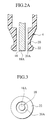
- the front horn 18 is setat its front end surface 18A substantially flush with the front end of the ring 22. As shown in FIG. 2B, it is also possible to displace the front end surface 18A rearwardly from the front end of the ring 22.
- the front end surface 18A of the front horn 18 is protruded from the front end of the covering member 20 by displacement "a", it is preferred that -5 mm ⁇ a ⁇ 10 mm. Setting the displacement "a" within the above range enables users to make efficient cleaning without any special skills.
- the front end of the front horn 18 when the front end of the front horn 18 is protruded from the covering member 20 in the forward direction, there is a fear that users may press the front horn 18 against a cloth surface to be cleaned with too much strength thereby to weaken the ultrasonic vibration of the horn.
- the front end of the covering member 20 (the ring 22 in the first embodiment) is applied to the cloth surface, whereby the front end surface 18A of the front horn 18 is prevented from being pressed hard on the cloth surface.
- the displacement "a" of the front end of the ultrasonic horn with respect to the cover 4 is set at - 5 mm ⁇ a ⁇ 10 mm.
- the cover 4 can be used in either case where any of the above arrangements is fixed or where the arrangement is detachably attached for change.
- the material of the cover 4 includes thermoplastic resin, thermosetting resin, metal, pulp and ceramics. The material is not limited to those as long as it can attain the object of preventing users from directly touching the front end of the horn, an object of this embodiment.
- a user holding the apparatus body 2 turns the switch 8 on to drive the vibrating section 3.
- the clothes are immersed in cleaning fluid to be moistened.
- the ring 22 is applied to a cloth surface of the clothes.
- the ring 22 is slid on the cloth surface to bring the front end surface 18A of the front horn 18 positively and appropriately into contact with the cloth surface.
- the front end surface 18A of the front horn 18 transmits ultrasonic vibration through the cleaning fluid to remove stains off the cloth surface.
- the front horn 18 is enclosed by the covering member 20 of the cover 4, which has an effect of preventing the user from directly touching the front horn 18. Further in this embodiment, the ring 22 slides on a cloth surface of clothes, leading the front end surface 18A of the front horn 18 to a prescribed point on the cloth surface.
- cylindrical piezoelectric elements having a diameter of 15 mm and a thickness of 4 mm
- a Langevin ultrasonic transducer is prepared as the vibrating section 3, the transducer having the piezoelectric elements held between the rear horn 17 and the front horn 18 made of aluminum at torque of 50kg-cm.
- the length of the front horn 18 is set at 32.8 mm and the rear horn 17 at 14.3 mm.
- the diameter of the rear horn is set at 15 mm.
- the resonant frequency is 50 kHz.
- tolerance in flatness is set at 0.005 mm.
- the front end surface 18A of the front horn 18 in A1 is ground to have a tolerance in flatness of 0.2 mm.
- the area of the front end surface 18A of the front horn 18 in A1 is set at 0.59 cm 2
- the ratio between area S1 of the front end surface of the horn and area S2 of the piezoelectric elements, S2/S1 is set at 3.0.
- the resonant frequency is set at 50 kHz as in A1.
- the area of the front end surface 18A of the front horn 18 in A1 is set at 1.75 cm 2 , S2/S1 is at 1.0, and the tolerance in flatness is at 0.005 mm.
- the front end surface 18A of the front horn 18 in A4 is ground to set the tolerance in flatness at 1.0 mm.
- S1 in A3 is set at 0.71 cm 2 .
- S2/S1 is accordingly 2.50.
- the resonant frequency is set at 50 kHz.
- Degree of cleanness is determined by the measurement of light reflectance before and after cleaning with a sample piece of white cotton cloth stained with mud.
- a square frame of a 4 cm side is applied to clean mud stains inside the square with the ultrasonic cleaning apparatus. The cleaning is performed for a minute with water continuously poured on the piece. After the cleaning, the sample piece is washed for five minutes, and then dried and ironed. Thereafter light reflectance of the piece is measured with the CM-3500d reflectometer manufactured by Minolta Co., Ltd. Light reflectance is measured for an area in a circle of a diameter of 3 cm.
- an output of 15W or less, especially 8W or less results in the rate of cleanness of 60% or less when the area of the horn front end surface is about 1.75 cm 2 as in A4 and A5, providing insufficient cleaning power.
- the area of the horn front end surface should be about 0.6 cm 2 .
- the horn front end surface area is reduced with an output of 8W or less, it has been found that the area of about 0.07 cm 2 exerts highly satisfactory cleaning power.
- the ratio of area S1 of the horn front end surface and area S2 of the piezoelectric elements, S2/S1, should be 3 or more.
- S2/S1 is preferably 3 or more.
- the words "an output of 8W or less" means a power supplied to the piezoelectric elements, that is, the ultrasonic transducer. The power is preferably from 1W to 8W.
- the front end surface area of the front horn 18 and the value of S2/S1 are set in the above-mentioned range, which provides higher cleaning effect with lower output. This leads to the ultrasonic cleaning apparatus 1 in small size with low energy consumption.
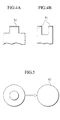
- FIG. 6 shows that it is preferred that the front horn 18 have a flat front surface and the tolerance in flatness be 0.2 mm or less.
- FIG. 7 shows part of an ultrasonic cleaning apparatus in a first modification of the first embodiment.
- the constitution of the modification is different from that of the first embodiment only in the shape of the front end of the front horn 18.
- the front end surface 18A of the front horn 18 in this modification has a recess 18B in the center.
- the area of the front end surface 18A except the recess 18B is set at 0.07 to 1.0 cm 2 .
- the ratio of area S1 of the horn front end surface to area S2 of the piezoelectric elements 14, 15, S2/S1, is set at 3 or more.
- This structure also provides good cleaning power with a low consumption power of about 8W as in the above embodiment. Further, the increased dimension of the front end of the front horn 18 larger than that of the first embodiment ensures good performance in ultrasonic transmission.
- FIG. 8 shows part of an ultrasonic cleaning apparatus in a second modification of this embodiment.
- a circular portion 18C at the periphery of the front end of the front horn 18 is set backward from the front end surface 18A.
- the area of the front end surface 18A is set at 0.07 to 1.0 cm 2
- S2/S1 is set at 3 or more.
- This modification also provides good cleaning power with low consumption power of about 8W as in the first embodiment. Further, the increased size dimension of the front end of the front horn 18 larger than that of the first embodiment ensures good performance in ultrasonic transmission.
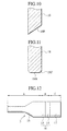
- FIG. 9 shows part of an ultrasonic cleaning apparatus in a third modification of this embodiment.
- the front horn 18 has, for example, a pair of cavities 18D formed in the front part.
- FIG. 10 shows part of an ultrasonic cleaning apparatus in a fourth modification of this embodiment.
- the front horn 18 has an oblique surface 18E at the front end to reduce the effective area thereof from which ultrasonic vibration is transmitted.
- the effective area of the front end can be set at 0.07 to 1.0 cm 2 .
- FIG. 11 shows part of an ultrasonic cleaning apparatus in a fifth modification of this embodiment.
- the front horn 18 has a curved surface 18F as an R surface formed at the rim of the front end surface 18A.
- Forming the curved surface 18F makes it possible to set the area of the front end surface 18A of the front horn 18 smaller than the section area of the front horn 18. Accordingly, the front horn 18 having an area almost identical to that of the piezoelectric elements 14, 15 can be joined with the elements 14, 15 to maintain good performance in ultrasonic transmission while front end surface area S1 can be set easily at 0.07 to 1.0 cm 2 . Further, the curved surface 18F formed at the front rim of the front horn 18 can prevent hooking of an article being cleaned, being smoothly slid on the article.
- the ultrasonic horn has a flat front end surface and the area of the front end surface is set at 0.07 to 1.0 cm 2 , which allows driving with low consumption power of 8W or less. This results in a compact ultrasonic cleaning apparatus exerting a sufficient effect in ultrasonic cleaning.
- the ratio of the section area of the piezoelectric elements to the front end surface area of the ultrasonic horn is set at 3 or more, which ensures good performance in ultrasonic transmission and improves the efficiency in utilizing ultrasonic vibration at the front end surface. This results in an ultrasonic cleaning apparatus with high cleaning efficiency and low consumption power.
- Tolerance of flatness of the front end surface of the ultrasonic horn is set at 0.2 mm or less, which allows a small ultrasonic cleaning apparatus with low consumption power to exert a sufficient effect in ultrasonic cleaning.
- the apparatus can be slid smoothly on an article being cleaned.
- This embodiment has a structure similar to that of the first embodiment. Like elements are given like reference characters and are not described in detail.
- length A of the front horn 18 is set at 33 mm
- length B of the transducer 16 is set at 8 mm
- length C of the rear horn 17 is set at 16 mm, for example.
- the diameter of the rear horn 17 is set at 15 mm, the same as the piezoelectric elements 14, 15.
- Area S1 of the front end surface of the front horn 18 is set at 0.3 cm 2 and area S2 of the piezoelectric elements is set at 1.77 cm 2 .
- the ratio of S2 to S1, S2/S1 is set at 5.9.
- This embodiment provides efficient cleaning with a low consumption power of 8W or less. Further, in this embodiment, the apparatus can exert good cleaning power over a wider range of ultrasonic vibration frequencies. Thus the lower consumption power of the ultrasonic transducer 16 is attained, which makes it possible to make the ultrasonic transducer 16 and the power source smaller and to make the apparatus usable in homes.
- the ultrasonic cleaning apparatus 1 with the vibrating section 3 in different settings is used to perform cleaning experiments described below by supplying an output of 8W to the transducer 16.
- the structure in experimental example B1 is the same as that of this embodiment, and length A of the front horn 18 is set at 33 mm, length B of the transducer 16 at 8 mm and length C of the rear horn 17 at 16 mm.
- the front horn 18 and the rear horn 17 are both made of aluminum.
- S1 of the front horn 18 is set at 0.3 cm 2 and S2 of the piezoelectric elements at 1.77 cm 2 to make S2/S1 5.9.
- the resonant frequency is set at 50 kHz.
- B2 A is set at 23 mm, B is at 8 mm and C is at 7.5 mm in the structure of B1.
- the front horn 18 and the rear horn 17 are both made of aluminum.
- S1 is set at 0.3 cm 2 and S2 at 1.77 cm 2 .
- the resonant frequency is set at 70 kHz.
- B3 A is set at 39 mm, B at 10 mm and C at 39 mm in the structure of B1.
- the front horn 18 and the rear horn 17 are both made of aluminum.
- S1 is set at 1.0 cm 2 and S2 at 1.77 cm 2 .
- S2/S1 is set at 1.77.
- the resonant frequency is set at 30 kHz.
- S1 is set at 0.59 cm 2 in the structure of B1.
- S2/S1 is 3.0.
- the resonant frequency is set at 58 kHz.
- B5 A is set at 45 mm, B at 8 mm and C at 45 mm in the structure of B1.
- the front horn 18 and the rear horn 17 are both made of aluminum.
- S1 is set at 0.3 cm 2 and S2 at 1.77 cm 2 .
- S2/S1 is set at 5.9.
- the resonant frequency is set at 42 kHz.
- A is set at 25 mm, B at 10 mm and C at 40 mm in the structure of B1.
- the front horn 18 and the rear horn 17 are both made of aluminum.
- S1 is set at 1.0 cm 2 and S2 at 1.77 cm 2 .
- S2/S1 is set at 1.77.
- the resonant frequency is set at 55 kHz.
- the conditions of BC/3A ⁇ 10A/(A+B+C) ⁇ AB/2C and S2/S1 is 3 or more are effective when the resonant frequency is in a 25 to 100 kHz frequency band.
- the apparatus when practically used produces large vibration noise and causes unpleasant touch. Further, a larger ultrasonic horn is required, which is inappropriate as an apparatus for cleaning stains in spots.
- a resonant frequency of 100 kHz or more it is difficult to raise cleaning power to a desirable value even if the above relationships are satisfied. This is because such higher frequencies cause water to vibrate from a vibration level in its entirety to a cross-linking level, which vibration is not suitable for cleaning.
- the embodiment and measurement results in the various settings described above are not intended to limit the present invention.
- Various modifications are possible within the intended purpose of the structure.
- the front horn 18 and the rear horn 17 are made of the same material to have the same property in ultrasonic transmission in this embodiment, the horns can be made of any materials which provide generally similar property in ultrasonic transmission.
- the materials having the generally identical properties in ultrasonic transmission means materials having compositions 90% or more identical.
- the front horn 18 and the rear horn 17 are made to have almost identical properties to meet the relationships of BC/3A ⁇ 10A/(A+B+C) ⁇ AB/2C and S2/S1 is 3 or more, thereby to attempt the improvement of efficiency in ultrasonic cleaning with a low consumption energy of 8W or less .
- materials having different properties in ultrasonic vibration have different speeds in transmitting vibration and therefore are easily unbalanced by vibration. Thus large vibration energy cannot be obtained.
- the front horn 18 and the rear horn 17 are made of aluminum, they can be made of another metal such as stainless steel or alloy. Further, the horns can be made of nonmetallic material such as ceramics including glass, alumina, and zirconia or plastics including polystylene, ABC or bakelite and compounds thereof. The nonmetallic material preferably has a sound wave velocity of 2000m/sec. or more.
- the same material used for the front horn and the rear horn increases precision in applying the above relationships in length.
- Nonmetallic material can be used for the horns, which has an effect of providing the ultrasonic transducer having lighter weight.
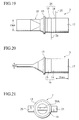
- the front horn 18 is configured to be gradually thinner from the proximal end to the front end.
- the front end surface 18A of the front horn 18 to be brought into contact with an article to be cleaned has a narrow rectangular shape.
- length "a" of the longer side (major axis) is set at 15 mm
- length "b" of the shorter side (minor axis) is at 2.5 mm
- the area is at 37.5 mm 2 .
- the front horn 18 is set at 28 mm in length and the rear horn at 14 mm.
- the rear horn 17 is set at 15 mm in diameter, the same as the piezoelectric elements 14, 15.
- the rear horn has stepped parts 17B of 5 mm length formed at opposite sides of the rear portion.
- An output of 6W is supplied to electrodes 25, 26 for the piezoelectric elements.
- the resonant frequency is 50 kHz.
- the cover 4 is not limited in structure to the one shown in the first embodiment. Various modifications are possible.
- the main axis (longer side) of the front end surface 18A of the front horn 18 is made to form a generally right angle with the running (advancing) direction so as to clean wider area.
- the cleaning rate is measured in a method similar to that in experimental example A1.
- Unevenness of cleaning rate is measured in the following manner. In measuring the degree of cleanness, an area to be cleaned is expanded to a square of a 10 cm side and is cleaned for the same time period (one minute). In measuring reflectance, 50 parts of a 8 mm diameter within the square are measured. A difference between maximum and minimum percentages in reflectance is used as an unevenness measure. Thus the smaller the difference is, the lower unevenness level is, resulting in good cleaning effect.
- length "b" of the minor axis is set at 1.5 mm and dimension ratio R is at 10 in the structure of C1.
- An output supplied is 8W.
- main axis length "a” is set at 10 mm and minor axis length "b” is at 3 mm to set R at 3.3, and the front end surface area of the front horn 18 is set at 30 mm 2 in the structure of C1.
- the length of the rear horn 17 is set at 25 mm.
- the diameter of the piezoelectric elements 14, 15 is set at 20 mm and area S2 to be joined to the element 14 is at 314 mm 2 in the structure of C1.
- the main axis length of the front end surface 18A is set at 15 mm, the minor axis length at 2.5 mm and front end surface area S1 is at 37.5 cm 2 .
- the main axis length is set at 20 mm
- the minor axis length is at 6 mm
- R is at 3.3
- front surface area S2 is at 120 mm 2 in the structure of C4.
- the minor axis length is set at 1.0 mm and dimension ratio R is at 15 in the structure of C1.
- An output supplied is 8W.
- the front horn 18 has a cylindrical shape of the same diameter (15 mm) as that of the piezoelectric elements 14, 15 in the structure of C1. An output of 8W is supplied.
- the diameter of the elements 14, 15 is set at 25 mm.
- the front end surface of the front horn 18 has a rectangular shape.
- the main axis length is set at 25 mm, the minor axis length is at 5 mm, dimension ratio R is at 5, the front end surface area is at 125 mm 2 , and the output supplied is at 8W.
- the main axis length is set at 30 mm
- the minor axis length is at 10 mm
- dimension ratio R is at 3
- the front end surface are is at 300 mm 2
- the output supplied is at 8W in the structure of C1.
- C1 to C5 show good results of cleaning rate of 75% or more and unevenness in cleaning rate of 7% or less with a low output of 8W or less.
- dimension ratio R is within the range of 3 ⁇ R ⁇ 10
- S1 is 314 mm 2 (3.14 cm 2 ) or less
- S2 is within the range of 20 mm 2 ⁇ S2 ⁇ 140 mm 2 , which is considered to provide good results.
- the piezoelectric element area is set at 4.96 cm 2 , larger than 3.14 cm 2 , so that the degree of cleanness is lowered and the unevenness in cleaning rate is larger.
- the front end surface 18A of the front horn 18 be in a rectangular or elliptic shape to have a width to be contacted with an article to be cleaned and dimension ratio R between the minor and major axes be set within the range of 3 ⁇ R ⁇ 10.
- S1 be 3. 14 cm 2 or less and S2 be 20 mm 2 ⁇ S2 ⁇ 140 mm 2 .
- the major axis length of the front end surface 18A of the front horn 18 be set at the same or less of that of the piezoelectric elements to be joined with the front horn 18.
- the embodiment described above is not intended to limit the present invention. Various modifications are possible within the intended purpose of the structure.
- the front end surface 18A of the front horn 18 has a rectangular shape in this embodiment, the surface 18A can have an elliptic shape to provide the same functions/effects.
- an ultrasonic cleaning apparatus in a small size which is drivable with a low consumption power and exerts sufficient effect in ultrasonic cleaning.
Applications Claiming Priority (6)
| Application Number | Priority Date | Filing Date | Title |
|---|---|---|---|
| JP2000130947 | 2000-04-28 | ||
| JP2000131113 | 2000-04-28 | ||
| JP2000129587 | 2000-04-28 | ||
| JP2000130947 | 2000-04-28 | ||
| JP2000131113A JP2001310095A (ja) | 2000-04-28 | 2000-04-28 | 超音波洗浄装置 |
| JP2000129587A JP2001310094A (ja) | 2000-04-28 | 2000-04-28 | 超音波洗浄装置 |
Publications (3)
| Publication Number | Publication Date |
|---|---|
| EP1149637A2 true EP1149637A2 (de) | 2001-10-31 |
| EP1149637A3 EP1149637A3 (de) | 2004-05-26 |
| EP1149637B1 EP1149637B1 (de) | 2007-02-28 |
Family
ID=27343259
Family Applications (1)
| Application Number | Title | Priority Date | Filing Date |
|---|---|---|---|
| EP01110027A Expired - Lifetime EP1149637B1 (de) | 2000-04-28 | 2001-04-26 | Horn für eine Vorrichtung zur Ultraschallreinigung |
Country Status (3)
| Country | Link |
|---|---|
| US (1) | US6493289B2 (de) |
| EP (1) | EP1149637B1 (de) |
| DE (1) | DE60126857T2 (de) |
Cited By (6)
| Publication number | Priority date | Publication date | Assignee | Title |
|---|---|---|---|---|
| CN104624467A (zh) * | 2015-01-23 | 2015-05-20 | 陕西师范大学 | 具有夹角结构的纵振动变幅杆 |
| CN105013686A (zh) * | 2015-07-29 | 2015-11-04 | 陕西师范大学 | 可换向的纵振动方向变换器的设计方法和应用 |
| EP3192911A4 (de) * | 2014-09-09 | 2018-03-28 | Haier Asia International Co., Ltd. | Fleckenentfernungsvorrichtung und fleckenentfernungseinheit |
| CN108978105A (zh) * | 2017-06-05 | 2018-12-11 | 青岛海尔洗衣机有限公司 | 一种手持式超声洗涤装置 |
| EP3659721A1 (de) * | 2018-11-27 | 2020-06-03 | Rolls-Royce plc | Veredelung einer oberfläche eines durch generative fertigung gefertigten bauteils |
| WO2020161382A1 (en) * | 2019-02-06 | 2020-08-13 | Altum Technologies Oy | Method and system for cleaning a device holding fluid |
Families Citing this family (25)
| Publication number | Priority date | Publication date | Assignee | Title |
|---|---|---|---|---|
| JP2002512312A (ja) | 1998-02-20 | 2002-04-23 | ザ、プロクター、エンド、ギャンブル、カンパニー | 音波または超音波を使用する衣類の染除去製品 |
| ES2217778T3 (es) | 1998-02-20 | 2004-11-01 | THE PROCTER & GAMBLE COMPANY | Producto para eliminar manchas de alfombras que usa ondas sonicas o ultrasonicas. |
| JP2002530480A (ja) | 1998-11-16 | 2002-09-17 | ザ、プロクター、エンド、ギャンブル、カンパニー | 音波または超音波を使用する洗浄製品 |
| WO2001036118A1 (en) * | 1999-11-16 | 2001-05-25 | The Procter & Gamble Company | Ultrasonic cleaning |
| AU1490101A (en) * | 1999-11-16 | 2001-05-30 | Procter & Gamble Company, The | Ultrasonic implement |
| ATE294031T1 (de) * | 1999-11-16 | 2005-05-15 | Procter & Gamble | Reinigungsverfahren welches ultraschallwellen verwendet |
| US20030084916A1 (en) * | 2001-10-18 | 2003-05-08 | Sonia Gaaloul | Ultrasonic cleaning products comprising cleaning composition having dissolved gas |
| US7004182B2 (en) * | 2001-10-18 | 2006-02-28 | The Procter & Gamble Company | Enhanced ultrasonic cleaning devices |
| JP3876167B2 (ja) * | 2002-02-13 | 2007-01-31 | 川崎マイクロエレクトロニクス株式会社 | 洗浄方法および半導体装置の製造方法 |
| US6853794B2 (en) * | 2002-07-02 | 2005-02-08 | Lightel Technologies Inc. | Apparatus for cleaning optical fiber connectors and fiber optic parts |
| JP3957605B2 (ja) * | 2002-10-07 | 2007-08-15 | シャープ株式会社 | 超音波洗浄装置 |
| CN100443036C (zh) * | 2003-02-25 | 2008-12-17 | 松下电工株式会社 | 超声波洗涤装置 |
| JP4428014B2 (ja) * | 2003-02-25 | 2010-03-10 | パナソニック電工株式会社 | 超音波生体洗浄装置 |
| JP4377666B2 (ja) * | 2003-12-04 | 2009-12-02 | ニスカ株式会社 | シート供給装置並びに画像読取装置 |
| CN100556059C (zh) * | 2003-12-04 | 2009-10-28 | 尼司卡股份有限公司 | 薄片重送检测方法和薄片供给器及采用它的图像读取装置 |
| US20050236012A1 (en) * | 2004-04-05 | 2005-10-27 | Thomas Josefsson | Apparatus and method for cleaning surfaces |
| TWI240028B (en) * | 2004-06-23 | 2005-09-21 | Ind Tech Res Inst | Portable ultrasonic cleaning machine |
| US20060130243A1 (en) * | 2004-12-17 | 2006-06-22 | Maytag Corporation | Continuous laundry cleaning appliance |
| US20060179946A1 (en) * | 2005-02-01 | 2006-08-17 | Beckman Coulter, Inc. | Method and apparatus for washing a probe or the like using ultrasonic energy |
| US7913561B2 (en) * | 2008-02-05 | 2011-03-29 | Olympus Medical Systems Corp. | Ultrasonic wave vibrating apparatus |
| CN101664743B (zh) * | 2008-09-03 | 2011-02-02 | 万荣辉 | 多功能声波清灰装置 |
| US10018113B2 (en) * | 2015-11-11 | 2018-07-10 | General Electric Company | Ultrasonic cleaning system and method |
| CN110520225A (zh) * | 2017-04-17 | 2019-11-29 | 夏普株式会社 | 超音波除菌洗净机 |
| CN110144694A (zh) * | 2019-04-30 | 2019-08-20 | 温锦华 | 一种超声波清洗/污物分离系统及其控制方法 |
| CN110079970A (zh) * | 2019-04-30 | 2019-08-02 | 温锦华 | 一种清洗及污物分离系统 |
Citations (3)
| Publication number | Priority date | Publication date | Assignee | Title |
|---|---|---|---|---|
| WO1988006927A1 (en) * | 1987-03-18 | 1988-09-22 | Mcqueen Douglas H | Ultrasonic instrument |
| JPH02250745A (ja) * | 1989-03-24 | 1990-10-08 | Toshiba Corp | 超音波加工機 |
| WO1999042555A1 (en) * | 1998-02-20 | 1999-08-26 | The Procter & Gamble Company | Garment stain removal product which uses sonic or ultrasonic waves |
Family Cites Families (9)
| Publication number | Priority date | Publication date | Assignee | Title |
|---|---|---|---|---|
| US4111546A (en) * | 1976-08-26 | 1978-09-05 | Xerox Corporation | Ultrasonic cleaning apparatus for an electrostatographic reproducing machine |
| US4386256A (en) * | 1978-01-17 | 1983-05-31 | Inoue-Japax Research Incorporated | Machining method and apparatus |
| CA1114770A (en) * | 1979-07-18 | 1981-12-22 | Anthony J. Last | Fabric treatment with ultrasound |
| DE3630183A1 (de) | 1986-09-04 | 1988-03-10 | Henkel Kgaa | Verbessertes verfahren zum waschen und reinigen von textilien (i) |
| US5032027A (en) * | 1989-10-19 | 1991-07-16 | Heat Systems Incorporated | Ultrasonic fluid processing method |
| JPH06218337A (ja) | 1993-01-25 | 1994-08-09 | Kaijo Corp | 超音波洗浄機 |
| ATE556543T1 (de) * | 1996-05-09 | 2012-05-15 | Crest Ultrasonics Corp | Ultraschallwandler |
| JPH10328472A (ja) | 1997-05-30 | 1998-12-15 | Lion Corp | 繊維製品の洗浄装置および洗浄方法 |
| JPH11147061A (ja) | 1997-11-14 | 1999-06-02 | Toppan Printing Co Ltd | 塗布装置 |
-
2001
- 2001-04-26 EP EP01110027A patent/EP1149637B1/de not_active Expired - Lifetime
- 2001-04-26 DE DE60126857T patent/DE60126857T2/de not_active Expired - Fee Related
- 2001-04-27 US US09/842,909 patent/US6493289B2/en not_active Expired - Fee Related
Patent Citations (3)
| Publication number | Priority date | Publication date | Assignee | Title |
|---|---|---|---|---|
| WO1988006927A1 (en) * | 1987-03-18 | 1988-09-22 | Mcqueen Douglas H | Ultrasonic instrument |
| JPH02250745A (ja) * | 1989-03-24 | 1990-10-08 | Toshiba Corp | 超音波加工機 |
| WO1999042555A1 (en) * | 1998-02-20 | 1999-08-26 | The Procter & Gamble Company | Garment stain removal product which uses sonic or ultrasonic waves |
Cited By (11)
| Publication number | Priority date | Publication date | Assignee | Title |
|---|---|---|---|---|
| EP3192911A4 (de) * | 2014-09-09 | 2018-03-28 | Haier Asia International Co., Ltd. | Fleckenentfernungsvorrichtung und fleckenentfernungseinheit |
| CN104624467A (zh) * | 2015-01-23 | 2015-05-20 | 陕西师范大学 | 具有夹角结构的纵振动变幅杆 |
| CN105013686A (zh) * | 2015-07-29 | 2015-11-04 | 陕西师范大学 | 可换向的纵振动方向变换器的设计方法和应用 |
| CN105013686B (zh) * | 2015-07-29 | 2017-07-11 | 陕西师范大学 | 可换向的纵振动方向变换器的设计方法和应用 |
| CN108978105A (zh) * | 2017-06-05 | 2018-12-11 | 青岛海尔洗衣机有限公司 | 一种手持式超声洗涤装置 |
| CN108978105B (zh) * | 2017-06-05 | 2021-12-14 | 青岛海尔洗衣机有限公司 | 一种手持式超声洗涤装置 |
| EP3659721A1 (de) * | 2018-11-27 | 2020-06-03 | Rolls-Royce plc | Veredelung einer oberfläche eines durch generative fertigung gefertigten bauteils |
| CN111299592A (zh) * | 2018-11-27 | 2020-06-19 | 劳斯莱斯有限公司 | 修整通过增材制造制备的部件的表面 |
| US11123840B2 (en) | 2018-11-27 | 2021-09-21 | Rolls-Royce Plc | Finishing a surface of a component made by additive manufacturing |
| CN111299592B (zh) * | 2018-11-27 | 2024-01-12 | 劳斯莱斯有限公司 | 修整通过增材制造制备的部件的表面 |
| WO2020161382A1 (en) * | 2019-02-06 | 2020-08-13 | Altum Technologies Oy | Method and system for cleaning a device holding fluid |
Also Published As
| Publication number | Publication date |
|---|---|
| US20010037537A1 (en) | 2001-11-08 |
| DE60126857D1 (de) | 2007-04-12 |
| EP1149637B1 (de) | 2007-02-28 |
| US6493289B2 (en) | 2002-12-10 |
| EP1149637A3 (de) | 2004-05-26 |
| DE60126857T2 (de) | 2007-10-31 |
Similar Documents
| Publication | Publication Date | Title |
|---|---|---|
| EP1149637A2 (de) | Horn für eine Vorrichtung zur Ultraschallreinigung | |
| US7549429B2 (en) | Ultrasonic washing device | |
| JP2714462B2 (ja) | 振動式かみそり | |
| KR100281945B1 (ko) | 초음파 미용기 | |
| US20060236500A1 (en) | Suction brush assembly having ultrasonic oscillator and a vacuum cleaner having the same | |
| US7849548B2 (en) | Extended reach ultrasonic toothbrush | |
| JP2001310165A (ja) | 超音波洗浄装置 | |
| JPH1015491A (ja) | 超音波振動用共振器の支持装置 | |
| CN109316328B (zh) | 美容装置 | |
| JP2001310094A (ja) | 超音波洗浄装置 | |
| JP4474883B2 (ja) | 超音波生体洗浄装置 | |
| JP2002186921A (ja) | 超音波洗浄装置 | |
| JP3586252B2 (ja) | 超音波歯ブラシ | |
| JP2002035485A (ja) | 超音波洗浄装置 | |
| US20050188540A1 (en) | Vibrating razor head | |
| JP2004195429A (ja) | 蒸気洗浄及び超音波洗浄装置 | |
| JP2002191892A (ja) | 超音波洗浄装置及び繊維布の洗浄方法 | |
| KR200326602Y1 (ko) | 초음파를 이용한 진동 치솔 | |
| JP2002191893A (ja) | 超音波洗浄装置 | |
| JP2002011424A (ja) | 超音波洗浄装置 | |
| KR200254481Y1 (ko) | 가정용 초음파 세척기 | |
| MXPA04010677A (es) | Dispositivo ultrasonico para el tratamiento del cabello y otras fibras. | |
| US20220142343A1 (en) | Connecting structure for electric cleaning device handle and head assembly | |
| KR20210033644A (ko) | 휴대용 무선 초음파 세척기 | |
| JP2003053084A (ja) | 超音波洗浄器 |
Legal Events
| Date | Code | Title | Description |
|---|---|---|---|
| PUAI | Public reference made under article 153(3) epc to a published international application that has entered the european phase |
Free format text: ORIGINAL CODE: 0009012 |
|
| 17P | Request for examination filed |
Effective date: 20010426 |
|
| AK | Designated contracting states |
Kind code of ref document: A2 Designated state(s): AT BE CH CY DE DK ES FI FR GB GR IE IT LI LU MC NL PT SE TR |
|
| AX | Request for extension of the european patent |
Free format text: AL;LT;LV;MK;RO;SI |
|
| PUAL | Search report despatched |
Free format text: ORIGINAL CODE: 0009013 |
|
| AK | Designated contracting states |
Kind code of ref document: A3 Designated state(s): AT BE CH CY DE DK ES FI FR GB GR IE IT LI LU MC NL PT SE TR |
|
| AX | Request for extension of the european patent |
Extension state: AL LT LV MK RO SI |
|
| RIC1 | Information provided on ipc code assigned before grant |
Ipc: 7D 06F 19/00 B Ipc: 7B 06B 1/06 A Ipc: 7D 06F 7/04 B Ipc: 7B 08B 3/12 B |
|
| AKX | Designation fees paid |
Designated state(s): DE FR GB |
|
| GRAP | Despatch of communication of intention to grant a patent |
Free format text: ORIGINAL CODE: EPIDOSNIGR1 |
|
| GRAS | Grant fee paid |
Free format text: ORIGINAL CODE: EPIDOSNIGR3 |
|
| GRAA | (expected) grant |
Free format text: ORIGINAL CODE: 0009210 |
|
| AK | Designated contracting states |
Kind code of ref document: B1 Designated state(s): DE FR GB |
|
| REG | Reference to a national code |
Ref country code: GB Ref legal event code: FG4D |
|
| REF | Corresponds to: |
Ref document number: 60126857 Country of ref document: DE Date of ref document: 20070412 Kind code of ref document: P |
|
| PGFP | Annual fee paid to national office [announced via postgrant information from national office to epo] |
Ref country code: DE Payment date: 20070426 Year of fee payment: 7 |
|
| EN | Fr: translation not filed | ||
| PLBI | Opposition filed |
Free format text: ORIGINAL CODE: 0009260 |
|
| PLAX | Notice of opposition and request to file observation + time limit sent |
Free format text: ORIGINAL CODE: EPIDOSNOBS2 |
|
| 26 | Opposition filed |
Opponent name: AEG HAUSGERAETE GMBH Effective date: 20071128 |
|
| GBPC | Gb: european patent ceased through non-payment of renewal fee |
Effective date: 20070528 |
|
| PG25 | Lapsed in a contracting state [announced via postgrant information from national office to epo] |
Ref country code: FR Free format text: LAPSE BECAUSE OF FAILURE TO SUBMIT A TRANSLATION OF THE DESCRIPTION OR TO PAY THE FEE WITHIN THE PRESCRIBED TIME-LIMIT Effective date: 20071019 |
|
| PLBB | Reply of patent proprietor to notice(s) of opposition received |
Free format text: ORIGINAL CODE: EPIDOSNOBS3 |
|
| PG25 | Lapsed in a contracting state [announced via postgrant information from national office to epo] |
Ref country code: GB Free format text: LAPSE BECAUSE OF NON-PAYMENT OF DUE FEES Effective date: 20070528 |
|
| PG25 | Lapsed in a contracting state [announced via postgrant information from national office to epo] |
Ref country code: FR Free format text: LAPSE BECAUSE OF FAILURE TO SUBMIT A TRANSLATION OF THE DESCRIPTION OR TO PAY THE FEE WITHIN THE PRESCRIBED TIME-LIMIT Effective date: 20070228 |
|
| PG25 | Lapsed in a contracting state [announced via postgrant information from national office to epo] |
Ref country code: DE Free format text: LAPSE BECAUSE OF NON-PAYMENT OF DUE FEES Effective date: 20081101 |
|
| PLBD | Termination of opposition procedure: decision despatched |
Free format text: ORIGINAL CODE: EPIDOSNOPC1 |
|
| PLAM | Termination of opposition procedure: information related to despatch of decision modified |
Free format text: ORIGINAL CODE: EPIDOSCOPC1 |
|
| PLBM | Termination of opposition procedure: date of legal effect published |
Free format text: ORIGINAL CODE: 0009276 |
|
| STAA | Information on the status of an ep patent application or granted ep patent |
Free format text: STATUS: OPPOSITION PROCEDURE CLOSED |
|
| 27C | Opposition proceedings terminated |
Effective date: 20090514 |