EP1146622A2 - Spannungsregler für einen Fahrzeuggenerator - Google Patents
Spannungsregler für einen Fahrzeuggenerator Download PDFInfo
- Publication number
- EP1146622A2 EP1146622A2 EP00121345A EP00121345A EP1146622A2 EP 1146622 A2 EP1146622 A2 EP 1146622A2 EP 00121345 A EP00121345 A EP 00121345A EP 00121345 A EP00121345 A EP 00121345A EP 1146622 A2 EP1146622 A2 EP 1146622A2
- Authority
- EP
- European Patent Office
- Prior art keywords
- control apparatus
- voltage
- voltage control
- light emitting
- input terminal
- Prior art date
- Legal status (The legal status is an assumption and is not a legal conclusion. Google has not performed a legal analysis and makes no representation as to the accuracy of the status listed.)
- Withdrawn
Links
Images


Classifications
-
- H—ELECTRICITY
- H02—GENERATION; CONVERSION OR DISTRIBUTION OF ELECTRIC POWER
- H02P—CONTROL OR REGULATION OF ELECTRIC MOTORS, ELECTRIC GENERATORS OR DYNAMO-ELECTRIC CONVERTERS; CONTROLLING TRANSFORMERS, REACTORS OR CHOKE COILS
- H02P9/00—Arrangements for controlling electric generators for the purpose of obtaining a desired output
- H02P9/08—Control of generator circuit during starting or stopping of driving means, e.g. for initiating excitation
-
- H—ELECTRICITY
- H02—GENERATION; CONVERSION OR DISTRIBUTION OF ELECTRIC POWER
- H02J—CIRCUIT ARRANGEMENTS OR SYSTEMS FOR SUPPLYING OR DISTRIBUTING ELECTRIC POWER; SYSTEMS FOR STORING ELECTRIC ENERGY
- H02J7/00—Circuit arrangements for charging or depolarising batteries or for supplying loads from batteries
- H02J7/14—Circuit arrangements for charging or depolarising batteries or for supplying loads from batteries for charging batteries from dynamo-electric generators driven at varying speed, e.g. on vehicle
- H02J7/16—Regulation of the charging current or voltage by variation of field
- H02J7/24—Regulation of the charging current or voltage by variation of field using discharge tubes or semiconductor devices
- H02J7/243—Regulation of the charging current or voltage by variation of field using discharge tubes or semiconductor devices with on/off action
-
- H—ELECTRICITY
- H02—GENERATION; CONVERSION OR DISTRIBUTION OF ELECTRIC POWER
- H02J—CIRCUIT ARRANGEMENTS OR SYSTEMS FOR SUPPLYING OR DISTRIBUTING ELECTRIC POWER; SYSTEMS FOR STORING ELECTRIC ENERGY
- H02J7/00—Circuit arrangements for charging or depolarising batteries or for supplying loads from batteries
- H02J7/0047—Circuit arrangements for charging or depolarising batteries or for supplying loads from batteries with monitoring or indicating devices or circuits
Definitions
- the present invention relates to a voltage control apparatus for a vehicle generator wherein an ignition switch and a charge lamp are connected in series so that a single input terminal is commonly used for these elements.
- a voltage control apparatus for a vehicle generator which has an input terminal for inputting a battery voltage through an ignition switch and a charge lamp and starts the operation when the voltage at the input terminal exceeds a predetermined value
- Japanese Patent No. 2707616 Japanese Patent No. 2707616
- Fig. 6 shows a circuit diagram of the voltage control apparatus disclosed in the Japanese Patent.
- the voltage control apparatus 1 shown in Fig. 6 is arranged in a manner that the voltage control apparatus includes an input terminal L for inputting the voltage of a battery 5 through an ignition switch 3 and a charge lamp 4 connected in series with the ignition lamp and starts the excitation of a rotary coil 21 of a vehicle generator 2 when the voltage at the input terminal L exceeds a predetermined value.
- the voltage control apparatus 1 further includes a comparison means 12 which generates an output signal when the voltage at the input terminal L exceeds another predetermined value lower than the aforesaid predetermined value, and a switch means 14 which operates in response to the output signal thereby to connect a leak compensation resistor 143 between the input terminal L and the ground.
- the voltage control apparatus 1 shown in Fig. 6 includes comparators 12, 13.
- the voltage of the input terminal L is applied to each of the negative "-" terminals of these comparators.
- Constant voltages V1, V2 are applied to the positive "+” terminals of the comparators 12, 13, respectively, wherein V1 ⁇ V2.
- a transistor 16 is connected to the output terminal of the comparator 12.
- a transistor 14 serving as a switch means is turned on in response to the output of the transistor 16 applied through a resistor 142.
- a transistor 1112 is connected to the output terminal of the comparator 13.
- a power transistor 11 is turned on in response to the output of the transistor 1112 applied through a resistor 1114.
- the transistor 14 and a transistor 152 are connected to a comparator 15 through transistors 141, 151, respectively.
- V3 a constant voltage
- reference numerals 22, 23 depict the stator coil and the full-wave rectifier of the vehicle generator 2 respectively.
- a resistor 144 provided between the input terminal L and the ground serves to lower the voltage at the input terminal L to the ground level upon the normal opening operation of the ignition switch 3.
- the power transistor 11 is turned on and off in response to a transistor 1111.
- a zener diode 1113 is provided on the base side of the transistor 1111.
- FIG. 7 An example of the conventional voltage control apparatus for a vehicle generator is shown in Fig. 7 in which a light emitting element such as a light emitting diode driven with a low dissipation power is employed as the charge lamp.
- a light emitting element such as a light emitting diode driven with a low dissipation power
- the charge lamp When the light emitting diode etc. is employed as the charge lamp as shown in Fig. 7, it is required to mount a current limit resistor in series with the light emitting diode etc. on a vehicle side in order to prevent the occurrence of such a phenomenon that a transistor 152 for turning on the light emitting diode etc. is broken by an overcurrent.
- the current limit resistor when the current limit resistor is mounted on the vehicle side, the arrangement of the apparatus on the vehicle side becomes complicated. Further, even in the case where the current limit resistor is inserted on the vehicle side, there arises a problem that, when a high voltage such as a battery voltage etc. is directly applied to the input terminal L due to the abnormality of the vehicle wiring etc., the transistor for driving the light emitting element (light emitting diode etc.) driven with a low dissipation power may be broken by an overcurrent.
- an object of the present invention is to provide a voltage control apparatus for a vehicle generator having a stable starting circuit which can start the voltage control circuit without breaking the voltage control apparatus even in an abnormal case that a high voltage is directly applied to the input terminal L of the voltage control apparatus.
- Another object of the invention is to provide a voltage control apparatus for a vehicle generator which eliminates a dedicated element such as a transistor etc. which has been employed merely to turning on and off the light emitting element and can turn on and off the light emitting element with a simple circuit arrangement.
- Still another object of the invention is to provide a voltage control apparatus for a vehicle generator which can prevent the occurrence of such a phenomenon that the light emitting element is always kept in a lightened state by a current for starting the operation of the voltage control apparatus which flows into the voltage control apparatus from the input terminal L through the light emitting element.
- the invention according to aspect 1 is characterized in that in a voltage control apparatus for a vehicle generator which has an input terminal for inputting the voltage of a battery through an ignition switch and a light emitting element connected in series with the ignition switch and driven by a low dissipation power and which starts the excitation of the rotor coil of the vehicle generator when the voltage at the input terminal exceeds a predetermined value, wherein a resistor for limiting the current flowing through the light emitting element is disposed between an element within the voltage control apparatus for driving the light emitting element and the input terminal.
- the invention according to aspect 2 is characterized in that in a voltage control apparatus for a vehicle generator which has an input terminal for inputting a voltage of a battery through an ignition switch and a light emitting element connected in series with the ignition switch and driven by a low dissipation power and which starts excitation of a rotor coil of the vehicle generator when a voltage at the input terminal exceeds a predetermined value, wherein the light emitting element is lightened by a current itself which is inputted into the input terminal for starting the operation of the voltage control apparatus.
- the invention according to aspect 3 is characterized, in the voltage control apparatus for a vehicle generator according to aspect 2, in that the light emitting element is coupled through the ignition switch to the base terminal of an NPN transistor for starting the operation of the voltage control apparatus so that the light emitting element is turned on by a current flowing into the base terminal.
- the invention according to aspect 4 is characterized in that in a voltage control apparatus for a vehicle generator which has an input terminal for inputting a voltage of a battery through an ignition switch and a light emitting element connected in series with the ignition switch and driven by a low dissipation power and which starts excitation of a rotor coil of the vehicle generator when a voltage at the input terminal exceeds a predetermined value, wherein a circuit for detecting the voltage of the input terminal and starting the voltage control apparatus is arranged to be shutdown or inoperable after the vehicle generator starts the electric power generation operation.
- the invention according to aspect 5 is characterized, in the voltage control apparatus for a vehicle generator according to aspect 4, in that after the circuit for detecting the voltage of the input terminal and starting the voltage control apparatus is shutdown after the vehicle generator starts electric power generation operation, the operation of a starting circuit for the voltage control apparatus is maintained by the output of one phase of the vehicle generator.
- the invention according to aspect 6 is characterized in that in a voltage control apparatus for a vehicle generator which has an input terminal for inputting a voltage of a battery through an ignition switch and a light emitting element connected in series with the ignition switch and driven by a low dissipation power and which starts excitation of a rotor coil of the vehicle generator when a voltage at the input terminal exceeds a predetermined value, wherein a circuit for detecting the voltage of the input terminal and starting the voltage control apparatus includes a field effect transistor.
- the invention according to aspect 7 is characterized in that a light emitting diode is used as the light emitting element.
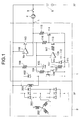
- Fig. 1 is a circuit diagram showing a voltage control apparatus for a vehicle generator according to the first embodiment of the invention.
- the voltage control apparatus 1 shown in Fig. 1 has an input terminal L for inputting the voltage of a battery 5 through an ignition switch 3 and a light emitting element (light emitting diode 4) driven by a low dissipation power which is connected in series with the ignition switch.
- the voltage control apparatus is arranged to start the excitation of the rotor coil 201 of a vehicle generator 2 when the voltage of the input terminal L exceeds a predetermined value.
- the voltage control apparatus 1 includes a current limit resistor 115 connected in series with a transistor 114 between the input terminal L and the collector of the transistor 114 for lightening the light emitting diode 4.
- the voltage control apparatus 1 further includes a comparator 108 having a negative "-" terminal to which the voltage of the input terminal L is applied and a positive "+” terminal to which a constant voltage Vy is inputted.
- the battery voltage is applied to the negative terminal of the comparator 108 through the light emitting diode 4 thereby to change the output of the comparator 108 from a high level to a low level, so that a transistor 110 is turned on.
- the transistor 110 is turned on, the voltage control apparatus 1 is started.
- a transistor 101 is supplied with a base current through a resistor 104 and hence a rotor coil 201 is supplied with a field current, whereby the vehicle generator 2 is placed in a state of capable of generating electric power.
- a comparator 109 When the vehicle generator 2 is in a state of before starting an electric power generation operation, a comparator 109 is supplied at its positive "+" terminal with zero voltage, so that the comparator 109 outputs a low level thereby to turn off a transistor 103.
- the transistor 114 for driving the light emitting diode 4 is supplied with a base current through a resistor 116 and turned on, whereby the light emitting diode 4 is turned on by the current flowing through the resistor 115.
- a transistor 103 and the transistor 101 are switched in response to a predetermined voltage which is obtained by dividing the output voltage of the vehicle generator 2 by resistors 106, 107 and a zener diode 105, the current flowing through the rotor coil 201 is intermittently controlled and so controlled to a predetermined value.
- the resistor for limiting the current flowing through the light emitting element is disposed between the input terminal and the element for driving the light emitting element within the voltage control apparatus.
- the second embodiment is arranged in a manner that in the voltage control apparatus for a vehicle generator which has an input terminal L for inputting the voltage of a battery through an ignition switch and a light emitting element (light emitting diode etc.) connected in series with the ignition switch and driven by a low dissipation power and which starts its operation when the voltage at the input terminal L exceeds a predetermined value, the light emitting element is lightened by the current itself which is inputted into the input terminal L for starting the operation of the voltage control apparatus thereby to eliminate a dedicated element for lightening the light emitting element.
- a light emitting element light emitting diode etc.
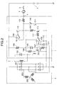
- Fig. 3 is a circuit diagram showing the voltage control apparatus for a vehicle generator according to the second embodiment.
- a transistor 122 when an ignition switch 3 is closed, a transistor 122 is supplied with a base current through a light emitting diode 4 serving as a charge lamp, a current limit resistor 115, a zener diode 120 and a resistor 126, so that the transistor 122 and a transistor 110 are turned on.
- a transistor 101 is supplied with a base current through a resistor 104 and so turned on, and hence a rotor coil 201 is supplied with a field current, whereby the vehicle generator 2 is placed in a state of capable of generating electric power.
- the light emitting diode 4 is lightened by the base current of the transistor 122 which is supplied to the input terminal L through the ignition switch 3 for driving the transistor 122.
- the transistor 122 is supplied with the base current due to the turning-on of the transistor 123, the circuit for supplying the base current for the transistor 101 is prevented from being shut down or inoperable.
- the element such as a dedicated transistor etc. which has been employed merely to turning on and off the light emitting element driven with a low dissipation power can be eliminated and the light emitting element can be turned on and off with the simple circuit arrangement.
- the third embodiment is arranged in a manner that in the voltage control apparatus for a vehicle generator which has an input terminal L for inputting the voltage of a battery through an ignition switch and a light emitting element (light emitting diode etc.) connected in series with the ignition switch and driven by a low dissipation power and which starts its operation when the voltage at the input terminal exceeds a predetermined value, the circuit for detecting the voltage of the input terminal L and starting the voltage control apparatus is arranged to be shutdown or inoperable after the vehicle generator starts the electric power generation operation.
- the circuit for detecting the voltage of the input terminal L and starting the voltage control apparatus is arranged to be shutdown or inoperable after the vehicle generator starts the electric power generation operation.
- Fig. 4 is a circuit diagram showing the voltage control apparatus for a vehicle generator according to the third embodiment.
- a transistor 144 when an ignition switch 3 is closed, a transistor 144 is supplied at its emitter terminal with a voltage through a light emitting diode 4 serving as a charge lamp and a current limit resistor 115.
- the transistor 133 since a transistor 133 is applied at its base terminal with the battery voltage through a resistor 148, the transistor 133 is in a conductive state.
- a transistor 122 is supplied with a base current through a resistor 146, so that a transistor 110 is turned on.
- a transistor 101 is supplied with a base current through a resistor 104 and so turned on.
- a rotor coil 201 is supplied with a field current, whereby the vehicle generator 2 is placed in a state of capable of generating electric power.
- the light emitting diode 4 is lightened by the base current of the transistor 122 flowing through the resistor 146 and the collector current of the transistor 133 flowing through a resistor 147.
- the transistor 110 is also turned off, whereby the circuit for supplying the base current for the transistor 101 is shut down or made inoperable.
- a transistor 131 is turned on by the output of the comparator 109 thereby to turn on the transistor 110, whereby the circuit for supplying the base current for the transistor 101 is kept to be operable to maintain the supply of the base current.
- the circuit for detecting the voltage of the input terminal L and starting the voltage control apparatus is arranged to be shutdown or inoperable after the vehicle generator starts the electric power generation operation.
- this embodiment can prevent the occurrence of such a phenomenon that the light emitting element is kept in a lightened state by the current for starting the operation of the voltage control apparatus which flows into the voltage control apparatus from the input terminal L through the light emitting element driven with a low dissipation power.
- the fourth embodiment is arranged in a manner that in the voltage control apparatus for a vehicle generator which has an input terminal L for inputting the voltage of a battery through an ignition switch and a light emitting element (light emitting diode etc.) connected in series with the ignition switch and driven by a low dissipation power and which starts its operation when the voltage at the input terminal L exceeds a predetermined value, the circuit for detecting the voltage of the input terminal L and starting the voltage control apparatus includes a field effect transistor.
- Fig. 5 is a circuit diagram showing the voltage control apparatus for a vehicle generator according to the fourth embodiment.
- a field effect transistor (FET) 151 is supplied with a voltage through a light emitting diode 4 serving as a charge lamp and a resistor 152.
- a transistor 110 is also turned on the moment the FET 151 is turned on, and so transistors 101 and 114 are supplied with base currents through resistors 104 and 116, respectively.
- a rotor coil 201 is supplied with a field current, so that a vehicle generator 2 is placed in a state of capable of generating electric power.
- the transistor 114 is also turned on, the light emitting diode 4 is lightened.
- the starting circuit for the voltage control circuit 1 of the vehicle generator 2 includes the field effect transistor (FET) 151. Since the FET 151 does not require any current to be supplied to the gate circuit thereof, the FET 151 keeps the conductive state whilst the current does not flow through the resistor 152. Thus, the operation of the starting circuit can be maintained without erroneously lightening the light emitting diode 4.
- FET field effect transistor
- the circuit for detecting the voltage of the input terminal L and starting the voltage control apparatus includes the field effect transistor.
- this embodiment can prevent the occurrence of such a phenomenon that the light emitting element is kept in a lightened state by the current flowing into the voltage control apparatus from the input terminal L.
- the resistor for limiting the current flowing through the light emitting element (light emitting diode etc.) driven with a low dissipation power is disposed between the input terminal and the element for driving the light emitting element within the voltage control apparatus.
- the voltage control circuit is prevented from being broken even in an abnormal case that the output voltage of the battery etc. is directly applied to the input terminal, and the stable starting circuit for the voltage control circuit can be arranged with the simple configuration.
- the light emitting element (light emitting diode etc.) driven with a low dissipation power is lightened by a current itself which is inputted into the input terminal for starting the operation of the voltage control apparatus.
- a dedicated transistor etc. which has been employed merely to turning on and off the light emitting element can be eliminated and the light emitting element can be turned on and off with the simple circuit arrangement.
- the circuit for detecting the voltage of the input terminal and starting the voltage control apparatus is arranged to be shutdown or inoperable after the vehicle generator starts the electric power generation operation.
- the light emitting element can be prevented from being kept in a lightened state by the current for starting the operation of the voltage control apparatus which flows into the voltage control apparatus from the input terminal L through the light emitting element(light emitting diode etc.).
- the circuit for detecting the voltage of the input terminal and starting the voltage control apparatus includes the field effect transistor.
- the field effect transistor there is no current for starting the operation of the voltage control apparatus which flows into the voltage control apparatus from the input terminal L through the light emitting element(light emitting diode etc.). Accordingly, the light emitting element is prevented from being kept in a lightened state by the current flowing into the voltage control apparatus from the input terminal.
Landscapes
- Engineering & Computer Science (AREA)
- Power Engineering (AREA)
- Control Of Eletrric Generators (AREA)
- Control Of Charge By Means Of Generators (AREA)
Applications Claiming Priority (2)
| Application Number | Priority Date | Filing Date | Title |
|---|---|---|---|
| JP2000109030A JP3544339B2 (ja) | 2000-04-11 | 2000-04-11 | 車両用発電機の電圧制御装置 |
| JP2000109030 | 2000-04-11 |
Publications (2)
| Publication Number | Publication Date |
|---|---|
| EP1146622A2 true EP1146622A2 (de) | 2001-10-17 |
| EP1146622A3 EP1146622A3 (de) | 2002-01-30 |
Family
ID=18621781
Family Applications (1)
| Application Number | Title | Priority Date | Filing Date |
|---|---|---|---|
| EP00121345A Withdrawn EP1146622A3 (de) | 2000-04-11 | 2000-10-10 | Spannungsregler für einen Fahrzeuggenerator |
Country Status (4)
| Country | Link |
|---|---|
| US (1) | US6943532B1 (de) |
| EP (1) | EP1146622A3 (de) |
| JP (1) | JP3544339B2 (de) |
| KR (1) | KR100573994B1 (de) |
Families Citing this family (6)
| Publication number | Priority date | Publication date | Assignee | Title |
|---|---|---|---|---|
| JP4239991B2 (ja) * | 2005-03-15 | 2009-03-18 | 株式会社デンソー | 発電制御装置 |
| JP4624422B2 (ja) * | 2005-08-31 | 2011-02-02 | 三菱電機株式会社 | 車両用発電機の制御装置 |
| US7332895B2 (en) * | 2006-01-17 | 2008-02-19 | Mobiletron Electronics, Co. | Regulator for eliminating noises generated by automotive power generator |
| JP4776682B2 (ja) * | 2006-03-07 | 2011-09-21 | 三菱電機株式会社 | 車両用交流発電機の出力電圧制御装置 |
| US8373318B2 (en) | 2010-04-30 | 2013-02-12 | Hamilton Sundstrand Corporation | Terminal lead insulator assembly for wound field synchronous machine |
| DE102013213042B4 (de) * | 2013-07-04 | 2022-05-25 | Ecom Instruments Gmbh | Elektronische Schaltungsanordnung zur Verwendung in einem explosionsgefährdeten Bereich |
Citations (1)
| Publication number | Priority date | Publication date | Assignee | Title |
|---|---|---|---|---|
| US4295087A (en) | 1979-06-12 | 1981-10-13 | Mitsubishi Denki Kabushiki Kaisha | Charge indicator circuit for a battery charging system |
Family Cites Families (31)
| Publication number | Priority date | Publication date | Assignee | Title |
|---|---|---|---|---|
| JPS5268911A (en) | 1975-12-05 | 1977-06-08 | Hitachi Ltd | Control apparatus for ac generator for vehicle |
| JPS5465312U (de) * | 1977-10-18 | 1979-05-09 | ||
| DE2809712C2 (de) * | 1978-03-07 | 1985-03-21 | Robert Bosch Gmbh, 7000 Stuttgart | Batterieladesystem, insbesondere für Kraftfahrzeuge |
| JPS5537881A (en) * | 1978-09-08 | 1980-03-17 | Nippon Denso Co | Automotive generator voltage controller |
| US4306184A (en) * | 1979-05-04 | 1981-12-15 | Nippondenso Co., Ltd. | Generation control appparatus for vehicle generators |
| JPS55162824A (en) * | 1979-06-07 | 1980-12-18 | Nippon Denso Co | Automotive generator generating controller |
| JPS56133948A (en) * | 1980-03-21 | 1981-10-20 | Nippon Denso Co | Vehicle generator generation indicator |
| US4379990A (en) * | 1980-05-22 | 1983-04-12 | Motorola Inc. | Fault detection and diagnostic system for automotive battery charging systems |
| JPS57138823A (en) * | 1981-02-18 | 1982-08-27 | Nippon Denso Co | Charge display unit |
| US4549128A (en) * | 1982-11-09 | 1985-10-22 | Mitsubishi Denki Kabushiki Kaisha | Charging generator controlling device |
| US4658200A (en) * | 1983-03-25 | 1987-04-14 | Mitsubishi Denki Kabushiki Kaisha | Protection circuit for voltage regulator of vehicle mounted generator |
| JPS6135125A (ja) * | 1984-07-25 | 1986-02-19 | 株式会社日立製作所 | 充電発電機の制御装置 |
| JPS6146200A (ja) | 1984-08-08 | 1986-03-06 | Nippon Denso Co Ltd | スイツチ投入検出回路 |
| US4665354A (en) * | 1984-08-08 | 1987-05-12 | Nippondenso Co., Ltd. | Battery voltage regulator for vehicles |
| US4687983A (en) * | 1985-01-17 | 1987-08-18 | Beyn Edgar J | Alternation control system having manual current selection capability and voltage dependent cutoff circuit |
| JPS62102396A (ja) * | 1985-10-29 | 1987-05-12 | 三菱電機株式会社 | 路線バス運行管理方法 |
| JPH01218333A (ja) * | 1988-02-24 | 1989-08-31 | Mitsubishi Electric Corp | 車両用交流発電機の制御装置 |
| JP2707616B2 (ja) * | 1988-07-26 | 1998-02-04 | 株式会社デンソー | 車両用発電機の電圧制御装置 |
| DE4038225A1 (de) * | 1990-11-30 | 1992-06-04 | Bosch Gmbh Robert | Verfahren und vorrichtung zur spannungsregelung in abhaengigkeit vom batterie-ladezustand |
| JPH0530800A (ja) * | 1991-07-18 | 1993-02-05 | Mitsubishi Electric Corp | 車両用交流発電機の制御装置 |
| KR940012793A (ko) * | 1992-11-24 | 1994-06-24 | 정몽원 | 차량용 발전기의 전압조정회로 |
| JP3028691B2 (ja) * | 1992-12-10 | 2000-04-04 | いすゞ自動車株式会社 | 過電圧保護回路付レギュレータ |
| JP3232739B2 (ja) * | 1993-02-08 | 2001-11-26 | 株式会社デンソー | スイッチ投入検出回路 |
| JPH0715886A (ja) | 1993-06-25 | 1995-01-17 | Nippondenso Co Ltd | 車両用発電機の出力電圧制御装置 |
| JPH07135740A (ja) * | 1993-11-09 | 1995-05-23 | Hitachi Ltd | 車両用充電発電機の制御装置 |
| JP3102981B2 (ja) * | 1993-12-28 | 2000-10-23 | 三菱電機株式会社 | 車両用交流発電機の出力制御装置 |
| JP3299380B2 (ja) * | 1994-04-27 | 2002-07-08 | 三菱電機株式会社 | 車両用交流発電機の制御装置 |
| EP0709944A1 (de) * | 1994-10-31 | 1996-05-01 | STMicroelectronics S.r.l. | Spannungsregler für ein Batterieladesystem |
| JP3415326B2 (ja) * | 1995-04-28 | 2003-06-09 | 株式会社デンソー | 車両用発電機の出力制御装置 |
| JP2976880B2 (ja) | 1996-03-25 | 1999-11-10 | 株式会社デンソー | 車両充電発電機の電圧調整装置 |
| EP1014557B1 (de) * | 1997-09-11 | 2010-06-02 | Mitsubishi Denki Kabushiki Kaisha | Regler für den wechselstromgenerator eines fahrzeuges |
-
2000
- 2000-04-11 JP JP2000109030A patent/JP3544339B2/ja not_active Expired - Lifetime
- 2000-10-10 EP EP00121345A patent/EP1146622A3/de not_active Withdrawn
- 2000-10-16 US US09/688,350 patent/US6943532B1/en not_active Expired - Fee Related
- 2000-12-18 KR KR1020000077789A patent/KR100573994B1/ko not_active IP Right Cessation
Patent Citations (1)
| Publication number | Priority date | Publication date | Assignee | Title |
|---|---|---|---|---|
| US4295087A (en) | 1979-06-12 | 1981-10-13 | Mitsubishi Denki Kabushiki Kaisha | Charge indicator circuit for a battery charging system |
Also Published As
| Publication number | Publication date |
|---|---|
| US6943532B1 (en) | 2005-09-13 |
| JP3544339B2 (ja) | 2004-07-21 |
| EP1146622A3 (de) | 2002-01-30 |
| JP2001298997A (ja) | 2001-10-26 |
| KR100573994B1 (ko) | 2006-04-25 |
| KR20010096535A (ko) | 2001-11-07 |
Similar Documents
| Publication | Publication Date | Title |
|---|---|---|
| JP4429387B2 (ja) | 三相発電機の出力電圧の制御装置 | |
| JP3299398B2 (ja) | 車両用交流発電機の出力制御装置 | |
| US4594631A (en) | Temperature protective circuit for a charging generator | |
| US6943532B1 (en) | Voltage control apparatus for vehicle generator having a light emitting diode | |
| EP0911941B1 (de) | Stromversorgungseinheit für Fahrzeuge | |
| KR100242333B1 (ko) | 내연기관의 점화시스템 | |
| JPH06284596A (ja) | 車両用交流発電機の電圧調整器 | |
| JPS6077656A (ja) | 車輌用直流発電機の故障表示方法 | |
| JPH07182052A (ja) | 過電圧保護装置 | |
| US4549128A (en) | Charging generator controlling device | |
| JPH0810969B2 (ja) | 車両用交流発電機の制御装置 | |
| KR0138531Y1 (ko) | 교류발전기의 전압 제어장치 | |
| CA1235740A (en) | Control apparatus for charging generator | |
| JP2707616B2 (ja) | 車両用発電機の電圧制御装置 | |
| JP3232739B2 (ja) | スイッチ投入検出回路 | |
| KR100193068B1 (ko) | 차량 교류발전기의 제어장치 | |
| KR100362803B1 (ko) | 전압 조정 장치 | |
| KR100221193B1 (ko) | 전압조정기의 안정화 회로 | |
| KR19980032120A (ko) | 차량용 발전기의 제어장치 | |
| KR100187177B1 (ko) | 알터네이터 출력부족 감지 장치 | |
| KR0123466Y1 (ko) | 차량용 배터리의 충전 제어회로 | |
| KR20000055759A (ko) | 차량용 발전기의 전압조정기 | |
| KR0175748B1 (ko) | 차량용 발전기의 과전압 발생 방지회로 | |
| JPS6033506Y2 (ja) | ランプ駆動回路 | |
| KR0126875B1 (ko) | 교류발전기의 외장접속형 전압조정기 |
Legal Events
| Date | Code | Title | Description |
|---|---|---|---|
| PUAI | Public reference made under article 153(3) epc to a published international application that has entered the european phase |
Free format text: ORIGINAL CODE: 0009012 |
|
| AK | Designated contracting states |
Kind code of ref document: A2 Designated state(s): DE FR GB Kind code of ref document: A2 Designated state(s): AT BE CH CY DE DK ES FI FR GB GR IE IT LI LU MC NL PT SE |
|
| AX | Request for extension of the european patent |
Free format text: AL;LT;LV;MK;RO;SI |
|
| PUAL | Search report despatched |
Free format text: ORIGINAL CODE: 0009013 |
|
| AK | Designated contracting states |
Kind code of ref document: A3 Designated state(s): AT BE CH CY DE DK ES FI FR GB GR IE IT LI LU MC NL PT SE |
|
| AX | Request for extension of the european patent |
Free format text: AL;LT;LV;MK;RO;SI |
|
| RIC1 | Information provided on ipc code assigned before grant |
Free format text: 7H 02J 7/24 A, 7H 02J 7/14 B |
|
| 17P | Request for examination filed |
Effective date: 20020424 |
|
| AKX | Designation fees paid |
Free format text: DE FR GB |
|
| RAP1 | Party data changed (applicant data changed or rights of an application transferred) |
Owner name: MITSUBISHI DENKI KABUSHIKI KAISHA |
|
| 17Q | First examination report despatched |
Effective date: 20081010 |
|
| STAA | Information on the status of an ep patent application or granted ep patent |
Free format text: STATUS: THE APPLICATION IS DEEMED TO BE WITHDRAWN |
|
| 18D | Application deemed to be withdrawn |
Effective date: 20160119 |