EP1142764A2 - Système de clé électronique pour véhicules - Google Patents
Système de clé électronique pour véhicules Download PDFInfo
- Publication number
- EP1142764A2 EP1142764A2 EP20010302869 EP01302869A EP1142764A2 EP 1142764 A2 EP1142764 A2 EP 1142764A2 EP 20010302869 EP20010302869 EP 20010302869 EP 01302869 A EP01302869 A EP 01302869A EP 1142764 A2 EP1142764 A2 EP 1142764A2
- Authority
- EP
- European Patent Office
- Prior art keywords
- electronic key
- vehicle
- vehicle apparatus
- corresponds
- code
- Prior art date
- Legal status (The legal status is an assumption and is not a legal conclusion. Google has not performed a legal analysis and makes no representation as to the accuracy of the status listed.)
- Granted
Links
Images


Classifications
-
- B—PERFORMING OPERATIONS; TRANSPORTING
- B60—VEHICLES IN GENERAL
- B60R—VEHICLES, VEHICLE FITTINGS, OR VEHICLE PARTS, NOT OTHERWISE PROVIDED FOR
- B60R25/00—Fittings or systems for preventing or indicating unauthorised use or theft of vehicles
- B60R25/20—Means to switch the anti-theft system on or off
- B60R25/24—Means to switch the anti-theft system on or off using electronic identifiers containing a code not memorised by the user
Definitions
- the present invention relates to a vehicular electronic key system for unlocking/locking doors and starting an engine.
- the electronic key system includes an electronic key and an on-vehicle apparatus which communicate with each by means of wireless communication and identify ID (identification data) therebetween to permit the door unlocking/locking operation and the engine starting operation.
- a Japanese Patent Provisional Publication No. (Heisei) 11-36675 discloses a vehicular electronic key system which executes unlocking door according to an identification result between a first ID code of an electronic key and a registered ID code and executes starting an engine according to an identification result between a second ID code sent of the electronic key and another registered ID code.
- the above vehicular electronic key system employs different ID codes for the door unlock and the engine start, respectively, and executes checking processes by respectively receiving the different ID codes by means of wireless communication. Therefore, this system has a characteristic that a time necessary for starting an engine becomes relatively long though a security to burglar is improved.
- An electronic key system is for a vehicle and comprises an electronic key and an on-vehicle apparatus.
- the electronic key has first ID (identification data), second ID, and third ID, which is shorter in data length than the second ID.
- the electronic key outputs the first ID, the second ID, and the third ID.
- the on-vehicle apparatus communicates with the electronic key by means of wireless communication.
- the on-vehicle apparatus has fourth ID, fifth ID, and sixth ID which is shorter in data length than the fifth ID.
- the on-vehicle apparatus permits starting an engine of the vehicle when the second ID outputted from the electronic key corresponds with the fifth ID.
- the on-vehicle apparatus permits starting the engine when the first ID outputted from the electronic key corresponds with the fourth ID and when the third ID outputted from the electronic key corresponds with the sixth ID.
- Fig. 1 is a schematic view showing an on-vehicle apparatus of an electronic key system according to an embodiment of the present invention.
- Fig. 2 is a schematic view showing an electronic key of the electronic key system.
- Fig. 3 is a view showing an ignition knob and an installed portion thereof in an instrument panel of a vehicle according to the embodiment of the present invention.
- Fig. 4 is a view showing a driver door according to the embodiment of the present invention.
- Fig. 5 is a top view showing communicable areas of door antennas installed near doors according to the embodiment of the present invention.
- Figs. 6A and 6B are views showing code structures of ID codes employed in the embodiment.
- Fig. 7A is a flowchart showing a door unlock process executed by the on-vehicle apparatus
- Fig. 7B is a flowchart showing a door unlock process executed by the electronic key in connection with the on-vehicle apparatus.
- Fig. 8A is a flowchart showing a part of an engine start process executed by the on-vehicle apparatus
- Fig. 8B is a flowchart showing a part of the engine start process executed by the electronic key in connection with the on-vehicle apparatus.
- Fig. 9A is a flowchart showing another part of the engine start process executed by the on-vehicle apparatus
- Fig. 9B is a flowchart showing another part of the engine start process executed by the electronic key in connection with the on-vehicle apparatus.
- Fig. 10 is a flowchart showing another part of an engine start process executed by the on-vehicle apparatus.
- Fig. 11A is a flowchart showing a part of a door lock process executed by the on-vehicle apparatus
- Fig. 11B is a flowchart showing a part of the door lock process executed by the electronic key in connection with the on-vehicle apparatus.
- FIGs. 1 to 11 there is shown an embodiment of a vehicular electronic key system according to the present invention.
- the vehicular electronic key system comprises an on-vehicle apparatus 1 shown in Fig. 1, an electronic key 20 shown in Fig. 2 and an ignition switch operated by an ignition knob 30 shown in Fig. 3.
- on-vehicle apparatus 1 of the vehicular electronic key system comprises passive control unit 11, first, second and third transmitters 2, 3 and 4, a receiver 12, an unlock and lock controller 13, an engine controller 15, a steering lock unit 16 and a buzzer 17.
- Unlock and lock controller 13 is connected to a door lock actuator 14 through which vehicular doors are opened and closed. Further, on-vehicle apparatus 1 is connected to various switches as explained later.
- electronic key 20 comprises an antenna 21, an electronic key controller 22 and a battery 23.
- Electronic key controller 22 comprises a CPU 22a and a nonvolatile memory 22b of a peripheral equipment.
- Electronic key controller 22 executes wireless communication with on-vehicle apparatus 1 through antenna 21.
- Nonvolatile memory 22b stores ID (Identification Data) codes for identifying a person having electronic key 20 as a permitted driver.
- Battery 23 is exchangeable and supplies electric power to electronic key controller 22.
- Electronic key 20 has no key plate employed in a conventional ignition key and is formed into a card which is further portable for a driver as compared with a conventional key.
- No cylinder unit for receiving electronic key 20 is provided in on-vehicle apparatus 1. It is not necessary for the driver to set electronic key 3 at a predetermined position, and the driver may merely carry electronic key 20.
- Ignition knob 30 is installed on an instrument panel in a passenger compartment of the vehicle as shown in Fig. 3, and no key hole is provided thereto since it is not necessary to insert electronic key 20 to the ignition switch unit.
- the ignition switch unit (not-shown) operated by ignition knob 30 is connected to passive control unit 11 and comprises a key switch 5, ignition-on switch 6, an engine start switch 7, and a steering lock unit 16 for locking a steering wheel.
- Ignition knob 30 is manually operated by the driver carrying electronic key 30.
- Steering lock unit 16 comprises a turn inhibiting latch (not shown) for inhibiting the turning of ignition knob 30 by locking ignition knob 30. Accordingly, by putting this turn inhibiting latch in a turnable state, ignition knob 30 and the steering wheel are put in the turnable state.
- ignition knob 30 By pushing ignition knob 30 set at a steering lock position denoted by LOCK in Fig. 3, key switch 5 is switched on. Further, by turning ignition knob 30 to an ignition-on position denoted by ON in Fig. 3, ignition-on switch 6 is switched on. By further turning ignition knob 30 to an engine start position denoted by START in Fig. 3, engine start switch 7 is switched on.
- Door handle switches 8a and 8b are provided in order to start a door unlock process as to doors for front vehicle occupants.
- Door lock switches 9a and 9b are provided in order to start a door lock process as to the doors for front seats.
- door lock switch 9a is installed at a portion near a door outside handle 41 for a driver door 40 and is operated from the outside of the vehicle when driver door 40 is locked.
- door lock switch 9b is installed at a portion near a door outside handle 41 for an assistant (front passenger) door.
- Door lock condition switches 10a and 10b are switches for detecting whether driver door 40 and assistant door 43 are locked or unlocked, respectively.
- Each of door lock condition switches 10a and 10b is switched off when a door lock mechanism (not shown) for each of front doors 40 and 43 is put in a lock condition, and is switched on when the door lock mechanism is put in an unlock condition.
- On-vehicle apparatus 1 executes wireless communication with electronic key 20 through first, second and third transmitters 2, 3 and 4 and a receiver 12.
- First transmitter 2 is installed at the driver seat or a ceiling above the driver seat.
- First transmitter 2 sends an engine start signal to electronic key 20 through an antenna 2a.
- communicable range between on-vehicle apparatus 1 and electronic key 20 is limited within a range of a passenger compartment near the driver seat.
- the communicable range may be limited in a range where first transmitter 2 can send the signal to electronic key 20 carried by a driver seated on the driver seat.
- second transmitter 3 is installed in the vicinity of door outside handle 41 of driver door 40 and sends a door lock signal and a door unlock signal through a driver door antenna 3a to electronic key 20 carried by the driver who is found near driver door 40.
- communicable range between on-vehicle apparatus 1 and electronic key 20 is limited within a range 42 of an outside near driver door 40 as shown in Fig. 5.
- the communicable table range 42 may be limited in a range where second transmitter 3 can send the signal to electronic key 20 carried by a driver who will execute a door lock by operating door lock switch 9a.
- third transmitter 4 is installed in the vicinity of door outside handle 41 of assistant door 43 and sends a door lock signal and a door unlock signal through an assistant-door antenna 4a to electronic key 20 carried by the driver who is found near assistant door 43.
- communicable range between on-vehicle apparatus 1 and electronic key 20 is limited within a range 44 of an outside near assistant door 43.
- the communicable range 44 may be limited in a range where third transmitter 4 can send the signal to electronic key 20 carried by a vehicle occupant who will execute a door lock by operating door lock switch 9b.
- Receiver 12 is installed at a rear parcel located at a vehicle rear portion, and receives an engine start request signal, a lock request signal, an unlock request signal and ID codes from electronic key 20 through an antenna 12a.
- Unlock and lock controller 13 comprises a CPU 13a and a nonvolatile memory 13b and executes locking and unlocking operations of driver door 40, assistant door 43, the rear-passenger doors by controlling door lock actuator 14.
- Engine controller 15 comprises a CPU 15a and a nonvolatile memory 15b and controls an engine speed and an output torque of an engine by controlling a throttle valve control apparatus, a fuel injection apparatus and an ignition apparatus.
- Passive control unit 11 comprises a CPU 11a and a nonvolatile memory 11b, and communicates with electronic key 20 via transmitters 2, 3 and 4 and receiver 12 by means of wireless communication. Passive control unit 11 executes the door unlocking and locking operations and the engine starting and stopping operations in a manner of controlling unlock and lock controller 13 and engine controller 15 according to the set conditions of ignition switches 5 to 7, door handle switches 8a and 8b, door lock switches 9a and 9b, and lock condition switches 10a and 10b.
- a buzzer 17 is provided in order to warn that electronic key 20 is mislaid in the vehicle, and is installed at a position from which a vehicle occupant outside of the vehicle can hear the alarm of buzzer 17. It is certain that a speaker may be provided instead of buzzer 7 and may inform the alarm condition to the vehicle occupant by voice.
- a first ID code is employed for locking and unlocking driver door 40, assistant door and the rear-passenger doors, and a second ID code different from the first ID code is employed for starting the engine of the vehicle through engine controller 15.
- the first and second ID codes are stored in memory 22b of electronic key 20 and are previously registered in memory 11b of passive control unit 11.
- passive control unit 11 of on-vehicle apparatus 1 checks whether the first ID code sent from electronic key 20 corresponds with the registered ID code in passive control unit 11.
- passive control unit 11 outputs a door unlock allowing signal to unlock and lock controller 13 to allow the door unlock operation and stores an ID correspondence result indicative of correspondence between ID code of electronic key 20 and ID code of passive control unit 11 in memory 11b.
- passive control unit 11 checks whether the second ID code sent from electronic key 2 corresponds with the registered ID code in passive control unit 11. According to the identification result of the first ID code, passive control unit 11 executes different identifying method.
- the passive control unit 11 requests electronic key 20 to send a first part of the second ID code.
- electronic key 20 sends only a first part of the second ID code to passive control unit 11.
- Passive control unit 11 checks whether the first part of the second ID code sent from electronic key 20 corresponds with a first part of the registered second ID code registered in the passive control unit 11. When the first part of the second ID code corresponds with the first part of the registered second ID code for engine start process, the engine starting is permitted.
- passive control unit 11 does not store the first ID code correspondence result.
- passive control unit 11 requests electronic key 20 to send all of the second ID code.
- passive control unit 11 checks whether the complete second ID code sent from electronic key 20 corresponds with the registered complete second ID code registered in memory 11b. When the second ID code received corresponds with the registered second ID code, the engine starting is permitted.
- the first part of the ID code is called as a compacted ID code, and all of the ID code is called as a complete ID code.
- the decision as to whether the engine is started is made on the basis of the identification result of the second ID code after the decision as to whether the door unlock operation is executed has been made on the basis of the identification of the first ID code, if the correspondence result of the first ID code has been already obtained, it is highly probable that a driver actually executing the engine starting operation is a proper driver to be permitted to drive the vehicle. Therefore, in this case, the decision as to the engine starting is made by identifying the compacted second ID without employing the complete second ID. This arrangement is capable of shortening an ID identifying process time necessary for the engine start while ensuring the security to burglar prevention.
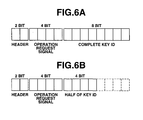
- Figs. 6A and 6B show structures of the complete ID code and the compacted ID code which are employed in the embodiment according to the present invention.
- the complete ID code is constituted by a header of 2 bits, an operation request signal of 4 bits and a key ID of 8 bits.
- the operation request signal includes the door lock request signal, the door unlock request signal and the engine start request signal.
- the compacted ID code employs a first part of the key ID in the complete ID code, and therefore the data length of the compacted ID code is shorter than that of the complete ID code by 4 bits.
- the header and the operation request signal of the compacted ID code are the same as those of the complete ID code.
- the structure of the ID code, the data length and the compacting method of the compacted ID code are not limited to this embodiment. Further, the compacted ID code may not employ a part of the key ID of the complete ID code and may employ a different key ID completely different from the key ID of the complete ID code. It is certain that the data length of the compacted ID code is set to be shorter than that of the complete ID code.
- Figs. 7A to 11 First, the door unlock process will be discussed with reference to Figs. 7A and 7B.
- the door unlock process of driver door 40 is discussed, the door unlock process of assistant door 43 is the same as the process of the driver door 40. Therefore, the explanation of the door unlock process of assistant door 43 is omitted herein.
- the operations shown by a flowchart of Fig. 7A is executed by on-vehicle apparatus 1, and is linked with the operations executed by electronic key 20.
- on-vehicle apparatus 1 decides whether door handle switch 8a is turned on according to the driver's operation for pulling door outside handle 41 of driver door 40.
- the routine proceeds to step S2.
- the routine repeats the step S1 until the affirmative decision is made at step S1.
- on-vehicle apparatus 1 sends the door unlock signal to electronic key 20 through transmitter 3 and antenna 3a installed to driver door 40.
- electronic key 20 starts awaiting the door unlock signal outputted from on-vehicle apparatus 1 in reply to the start of this door unlock process.
- electronic key 20 executes an operation of step S3 that receives the door unlock signal from the on-vehicle apparatus 1.
- step S3 electronic key 20 decides whether the door unlock signal is received.
- the routine of Fig. 7B jumps to an end step to terminate the operation of the door unlock process.
- the routine proceeds to step S4 wherein electronic key 20 outputs the door unlock request and the complete first ID code to on-vehicle apparatus 1. Thereafter, the routine executed by electronic key 20 is terminated.
- on-vehicle apparatus 1 checks for a predetermined time period whether receiver 12 has received the door unlock request and the complete first ID code from electronic key 20 through antenna 12a. When the door unlock request and the complete first ID code are received, the routine proceeds to step S6. When receiver 12 does not receive the door unlock request and the complete first ID code within the predetermined time period, the routine proceeds to an end step to terminate the present routine.
- on-vehicle apparatus 1 checks whether the complete first ID code sent from electronic key 20 corresponds with the registered complete ID code (corresponding to the first ID code) for door unlock process.
- the routine proceeds to step S7.
- the routine proceeds to the end step.
- step S7 on-vehicle apparatus 1 unlocks both doors 40 and 43 by controlling unlock and lock controller 13, and stores the correspondence result of the first ID code in memory 11b of passive control unit 11.
- step S7 is not executed, that is, when the negative decision is made at step S5 or S6, the routine is terminated without unlocking doors 40 and 43.
- on-vehicle apparatus 1 decides whether ignition knob 30 is operated by a driver. When the decision at step S11 is affirmative, that is, when ignition knob 30 is pushed by the driver, key switch 5 is switched on, and the engine start process is started. When the decision at step S11 is negative, on-vehicle apparatus 1 repeats step S11 for a predetermined time period.
- step S12 on-vehicle apparatus 1 checks whether the correspondence of the first ID code has been stored in memory 11b.
- the routine proceeds to step S13.
- the routine jumps to step S21 of Fig. 9A.
- on-vehicle apparatus 1 outputs the engine start signal and the compacted ID code requesting signal to electronic key 20 through first transmitter 2 and antenna 2a.
- electronic key 20 starts awaiting the engine start signal and the compacted ID request signal in reply to the start of the engine start process of Fig. 8A.
- step S14 electronic key 20 decides whether the engine start signal and the compacted ID request signal are received.
- the routine of Fig. 8B jumps to an end step to terminate the operation of the electronic key 20.
- the routine proceeds to step S15 wherein electronic key 20 outputs the engine start request signal and the compacted second ID signal to on-vehicle apparatus 1. Thereafter, the routine executed by electronic key 20 is terminated.
- on-vehicle apparatus 1 checks for a predetermined time period whether on-vehicle apparatus 1 has received the engine start request signal and the compacted second ID through antenna 12a and receiver 12.
- the routine jumps to an end block to terminate the routine of Fig. 8A.
- the routine proceeds to step S17.
- on-vehicle apparatus 1 checks whether the compacted second ID sent from electronic key 20 corresponds with a part corresponding to the compacted section of the registered complete second ID code registered in memory 11b.
- the routine proceeds to step S31 of Fig. 10.
- the routine proceeds to the end step to terminate the engine start process.
- on-vehicle apparatus 1 when on-vehicle apparatus 1 does not receive the engine start request signal and the compacted second ID code signal from electronic key 20, or when the received compacted second ID code does not correspond with the registered compacted second ID code, on-vehicle apparatus 1 inhibits the engine start and terminates the engine start process.
- on-vehicle apparatus 1 receives the engine start request signal and the compacted second ID code signal from electronic key 20 and when the received compacted second ID code corresponds with the registered compacted second ID code, the routine of on-vehicle apparatus 1 proceeds to step S31 shown in Fig. 10.
- on-vehicle apparatus 1 turns a knob turn inhibiting latch toward the unlock position by controlling steering lock unit 16.
- knob turn inhibiting latch By turning the knob turn inhibiting latch to the unlock position, ignition knob 30 and the steering wheel are put in the turnable states, respectively.
- on-vehicle apparatus 1 decides from a condition of ignition-on switch 6 whether ignition knob 30 is turned to ON position.
- ignition knob 30 is turned to ON position, that is, when ignition-on switch 6 is switched on, the routine proceeds to step S33 wherein passive control unit 11 of on-vehicle apparatus 1 outputs an engine start permitting signal to engine controller 15.
- the routine repeats step S32 until ignition knob 30 is turned to ON position.
- step S34 on-vehicle apparatus 1 checks from a condition of engine start switch 7 whether ignition knob 30 is turned to START position.
- ignition knob 30 is turned to START position, that is, when engine start switch 7 is switched on, the routine proceeds to step S35 wherein on-vehicle apparatus 1 starts the engine in a manner that passive controller 11 commands engine controller 15 to start the engine.
- the routine repeats step S34.
- step S36 on-vehicle apparatus 1 checks from the condition of ignition-on switch 6 whether ignition knob 30 is turned to ACC position.
- ignition knob 30 is turned to ACC position, that is, when ignition-on switch 6 is switched off
- the routine proceeds to step S37 wherein on-vehicle apparatus 1 stops the engine by controlling engine controller 15.
- the routine repeats step S36.
- on-vehicle apparatus 1 checks from a condition of key switch 5 whether ignition knob 30 is turned to LOCK position.
- the routine proceeds to step S39 wherein on-vehicle apparatus 1 moves knob turn inhibiting latch to the lock position by controlling steering lock unit 16. This operation puts ignition knob 30 and the steering wheel in the locked state.
- the routine proceeds to an end step to terminate the present routine.
- step S12 in Fig. 8A when the decision at step S12 in Fig. 8A is negative, that is, when the correspondence of the first ID code has not been stored in memory 11b, the routine jumps to step S21 of Fig. 9A.
- step S21 on-vehicle apparatus 1 sends the engine start signal to electronic key 20.
- electronic key 20 starts an operation shown in Fig. 9B in reply to the engine start process.
- step S22 electronic key 20 decides whether the engine start signal is received.
- the routine proceeds to step S23 wherein electronic key 20 outputs the engine start request and the complete second ID code to on-vehicle apparatus 1.
- on-vehicle apparatus 1 checks for a predetermined time period whether the engine start request signal and the complete second ID code are outputted by electronic key 20.
- the routine executed by on-vehicle apparatus 1 proceeds to step S25.
- the routine executed by on-vehicle apparatus 1 proceeds to an end step to terminate the engine start process.
- on-vehicle apparatus 1 checks whether the complete second ID code received corresponds with the complete second ID code previously stored in memory 11b. When the received complete second ID code corresponds with the registered complete second ID code, the routine proceeds to step S31 discussed above. When the received complete second ID code does not correspond with the registered complete second ID code, the routine proceeds to the end step to terminate the engine start process.
- on-vehicle apparatus 1 decides whether door lock switch 9a of driver door 40 is switched on according to the driver's operation for pushing door lock switch 9a.
- the routine proceeds to step S42.
- the routine repeats the step S41 until the affirmative decision is made at step S41.
- on-vehicle apparatus 1 sends the door lock signal to electronic key 20 through second transmitter 3 and antenna 3a in driver door 40.
- electronic key 20 starts awaiting the door lock signal outputted from on-vehicle apparatus 1, in reply to the start of this door lock process.
- step S43 electronic key 20 decides whether the door lock signal is received.
- the routine proceeds to step S44 wherein electronic key 20 outputs the door lock request signal and the complete first ID code to on-vehicle apparatus 1.
- on-vehicle apparatus 1 checks for a predetermined time period whether receiver 12 has received the door lock request signal and the complete first ID code from electronic key 20 through antenna 12a. When the door lock request signal and the complete first ID code signal are received, the routine proceeds to step S46. When receiver 12 does not receive the door lock request and the complete first ID code within the predetermined time period, the routine proceeds to step S48 wherein on-vehicle apparatus 1 generates alarm and inhibits the locking of doors 40 and 43.
- on-vehicle apparatus 1 checks whether the complete first ID code sent from electronic key 20 corresponds with the registered complete first ID code. When the complete first ID code sent from electronic key 20 corresponds with the registered complete first ID code stored in memory 11b, the routine proceeds to step S47. When the complete first ID code does not correspond with the registered complete ID code, the routine proceeds to step S48.
- on-vehicle apparatus 1 executes the locking of both doors 40 and 43 by controlling unlock and lock controller 13, and stores the correspondence of the first ID code in memory 11b.
- passive control unit 11 controls unlock and lock controller 13 to lock doors 40 and 43 by operating door lock actuator 14, and deletes the data indicative of the correspondence of the first ID code from memory 11b.
- step S48 on-vehicle apparatus 1 does not executes the locking operations of doors 40 an d43 and generates alarm for a predetermined time period. Thereafter, the routine proceeds to an end step to terminate this door lock routine.
- the first ID code for door unlock process may be stored in memory 13b of unlock and lock controller 13 and the second ID code for engine start process may be stored in memory 15b of engine controller 15.
Applications Claiming Priority (2)
| Application Number | Priority Date | Filing Date | Title |
|---|---|---|---|
| JP2000100972A JP3536774B2 (ja) | 2000-04-03 | 2000-04-03 | 車両用電子キー装置 |
| JP2000100972 | 2000-04-03 |
Publications (3)
| Publication Number | Publication Date |
|---|---|
| EP1142764A2 true EP1142764A2 (fr) | 2001-10-10 |
| EP1142764A3 EP1142764A3 (fr) | 2004-05-26 |
| EP1142764B1 EP1142764B1 (fr) | 2008-06-11 |
Family
ID=18615101
Family Applications (1)
| Application Number | Title | Priority Date | Filing Date |
|---|---|---|---|
| EP20010302869 Expired - Lifetime EP1142764B1 (fr) | 2000-04-03 | 2001-03-28 | Système de clé électronique pour véhicules |
Country Status (4)
| Country | Link |
|---|---|
| US (1) | US6876292B2 (fr) |
| EP (1) | EP1142764B1 (fr) |
| JP (1) | JP3536774B2 (fr) |
| DE (1) | DE60134356D1 (fr) |
Cited By (3)
| Publication number | Priority date | Publication date | Assignee | Title |
|---|---|---|---|---|
| EP1336938A2 (fr) * | 2002-02-15 | 2003-08-20 | Alps Electric Co., Ltd. | Dispositif monté sur véhicule avec unité de commande de communication |
| EP1382500A1 (fr) * | 2002-07-09 | 2004-01-21 | Alps Electric Co., Ltd. | Procédé pour l'ouverture sans clée et l'authentification auprès d'un système d'immobilisation |
| EP1336939A3 (fr) * | 2002-02-15 | 2004-04-14 | Alps Electric Co., Ltd. | Dispositif monté sur véhicule avec unité de commande de communication |
Families Citing this family (14)
| Publication number | Priority date | Publication date | Assignee | Title |
|---|---|---|---|---|
| JP2003097113A (ja) * | 2001-09-21 | 2003-04-03 | Fujitsu Ten Ltd | 車両用ドアロック装置 |
| JP4126224B2 (ja) * | 2002-12-19 | 2008-07-30 | 株式会社東海理化電機製作所 | エンジン始動制御装置 |
| JP4172297B2 (ja) * | 2003-03-17 | 2008-10-29 | 三菱電機株式会社 | 車両等の盗難防止装置 |
| JP2005083011A (ja) * | 2003-09-05 | 2005-03-31 | Denso Corp | 車両用電子キーシステムの携帯機及び車両用電子キーシステム |
| JP4385871B2 (ja) * | 2004-06-30 | 2009-12-16 | トヨタ自動車株式会社 | 車両盗難防止装置 |
| US20060238299A1 (en) * | 2005-04-22 | 2006-10-26 | Downey Richard T | Electrical enabling device |
| US20070241862A1 (en) * | 2006-04-12 | 2007-10-18 | Dimig Steven J | Transponder authorization system and method |
| JP4368882B2 (ja) * | 2006-10-27 | 2009-11-18 | アルプス電気株式会社 | パッシブキーレスエントリー装置 |
| US20080258886A1 (en) * | 2007-04-17 | 2008-10-23 | Summerlin Pamela L | Key locator and method of use thereof |
| JP2009062688A (ja) * | 2007-09-04 | 2009-03-26 | Tokai Rika Co Ltd | 車両用通信システム |
| US20100052848A1 (en) * | 2008-08-26 | 2010-03-04 | Nissan Technical Center North America, Inc. | Remote vehicle operating system |
| JP5164798B2 (ja) * | 2008-11-06 | 2013-03-21 | オムロンオートモーティブエレクトロニクス株式会社 | 車両認証制御装置 |
| DE202009018205U1 (de) * | 2009-06-02 | 2011-05-05 | Volkswagen Ag | Vorrichtung zur Betätigung eines Schließelements eines Fahrzeugs |
| CN109677359B (zh) * | 2019-02-11 | 2021-01-12 | 广州优创电子有限公司 | 汽车启动方法、装置和移动终端 |
Citations (2)
| Publication number | Priority date | Publication date | Assignee | Title |
|---|---|---|---|---|
| JPH1136675A (ja) | 1997-07-23 | 1999-02-09 | Toyota Motor Corp | 車両用電子キーシステム |
| JP2000100972A (ja) | 1998-09-18 | 2000-04-07 | Seiko Epson Corp | 半導体装置 |
Family Cites Families (12)
| Publication number | Priority date | Publication date | Assignee | Title |
|---|---|---|---|---|
| DE2928913B1 (de) * | 1979-07-18 | 1980-09-25 | Bayerische Motoren Werke Ag | Diebstahl-Sicherungsvorrichtung fuer Kraftfahrzeuge |
| DE69220016T2 (de) * | 1991-12-27 | 1998-01-02 | Zexel Corp | Verriegelungssystem |
| IT1260963B (it) * | 1993-08-06 | 1996-04-29 | Weber Srl | Dispositivo di sicurezza per un sistema antifurto per mezzi di locomozione |
| JPH08246728A (ja) * | 1995-03-13 | 1996-09-24 | Nissan Motor Co Ltd | キーレスエントリー装置 |
| US6140938A (en) | 1995-04-14 | 2000-10-31 | Flick; Kenneth E. | Remote control system suitable for a vehicle and having remote transmitter verification |
| DE19516992C1 (de) * | 1995-05-09 | 1996-04-04 | Siemens Ag | Verfahren zum Betreiben einer Diebstahlschutzeinrichtung für ein Kraftfahrzeug und Diebstahlschutzeinrichtung |
| JP3380368B2 (ja) * | 1995-06-05 | 2003-02-24 | 三菱電機株式会社 | 車両用盗難防止装置 |
| DE19533309A1 (de) * | 1995-09-08 | 1997-03-13 | Bayerische Motoren Werke Ag | Schlüssel für Kraftfahrzeuge |
| JPH1138875A (ja) | 1997-07-17 | 1999-02-12 | Masahiro Yagisawa | 有限環上の2次式に基づく暗号化装置および復号化装置 |
| US6031466A (en) * | 1998-03-23 | 2000-02-29 | D.S.P.C. Technologies Ltd. | Method for reducing power consumption in wait-mode |
| DE19839478A1 (de) * | 1998-08-29 | 2000-03-09 | Bosch Gmbh Robert | Zugangs- und Start/Fahrberechtigungssystem für ein Kraftfahrzeug |
| JP4603640B2 (ja) * | 1999-04-14 | 2010-12-22 | 富士通テン株式会社 | 遠隔制御装置および遠隔制御用受信装置 |
-
2000
- 2000-04-03 JP JP2000100972A patent/JP3536774B2/ja not_active Expired - Fee Related
-
2001
- 2001-03-28 EP EP20010302869 patent/EP1142764B1/fr not_active Expired - Lifetime
- 2001-03-28 DE DE60134356T patent/DE60134356D1/de not_active Expired - Lifetime
- 2001-03-29 US US09/819,647 patent/US6876292B2/en not_active Expired - Fee Related
Patent Citations (2)
| Publication number | Priority date | Publication date | Assignee | Title |
|---|---|---|---|---|
| JPH1136675A (ja) | 1997-07-23 | 1999-02-09 | Toyota Motor Corp | 車両用電子キーシステム |
| JP2000100972A (ja) | 1998-09-18 | 2000-04-07 | Seiko Epson Corp | 半導体装置 |
Cited By (7)
| Publication number | Priority date | Publication date | Assignee | Title |
|---|---|---|---|---|
| EP1336938A2 (fr) * | 2002-02-15 | 2003-08-20 | Alps Electric Co., Ltd. | Dispositif monté sur véhicule avec unité de commande de communication |
| EP1336938A3 (fr) * | 2002-02-15 | 2004-04-14 | Alps Electric Co., Ltd. | Dispositif monté sur véhicule avec unité de commande de communication |
| EP1336939A3 (fr) * | 2002-02-15 | 2004-04-14 | Alps Electric Co., Ltd. | Dispositif monté sur véhicule avec unité de commande de communication |
| US6995653B2 (en) | 2002-02-15 | 2006-02-07 | Alps Electric Co., Ltd. | Vehicle-mounted device communication controller |
| US7161467B2 (en) | 2002-02-15 | 2007-01-09 | Alps Electric. Co., Ltd. | Vehicle-mounted device communication controller |
| EP1382500A1 (fr) * | 2002-07-09 | 2004-01-21 | Alps Electric Co., Ltd. | Procédé pour l'ouverture sans clée et l'authentification auprès d'un système d'immobilisation |
| US7002449B2 (en) | 2002-07-09 | 2006-02-21 | Alps Electric Co., Ltd. | Keyless entry for executing immobilizer authentication |
Also Published As
| Publication number | Publication date |
|---|---|
| EP1142764B1 (fr) | 2008-06-11 |
| EP1142764A3 (fr) | 2004-05-26 |
| US20010026213A1 (en) | 2001-10-04 |
| JP3536774B2 (ja) | 2004-06-14 |
| JP2001279972A (ja) | 2001-10-10 |
| DE60134356D1 (de) | 2008-07-24 |
| US6876292B2 (en) | 2005-04-05 |
Similar Documents
| Publication | Publication Date | Title |
|---|---|---|
| EP1142764B1 (fr) | Système de clé électronique pour véhicules | |
| EP1143090B1 (fr) | Système de clef électronique pour véhicule | |
| EP1712438A2 (fr) | Système antivol pour véhicule | |
| JP4742979B2 (ja) | キーレスエントリシステム | |
| JPH08268228A (ja) | 車両盗難防止装置 | |
| US20090058597A1 (en) | Vehicle communication system | |
| EP0985789B1 (fr) | Appareil de commande à distance et méthode de commande à distance | |
| JP3588677B2 (ja) | 車両用電子キー装置 | |
| JP3589188B2 (ja) | 車両用電子キー装置 | |
| EP0905337B1 (fr) | Interrupteur de démarrage pour un véhicule et système associé | |
| JP3799961B2 (ja) | 車両用電子キー装置 | |
| JP2003127831A (ja) | 車両用電子キー装置 | |
| EP1365258B1 (fr) | Dispositif électronique d'immobilisation d'un véhicule et procédé pour contrôler le démarrage d'un véhicule | |
| EP1339026B1 (fr) | Appareil à clé électronique pour véhicule et procédé d'annulation du blocage pour dispositif de blocage de rotation | |
| JP3598929B2 (ja) | 車両用電子キー装置 | |
| JP3229574B2 (ja) | 車両用電子キー装置 | |
| JP3930386B2 (ja) | 電子キーシステム | |
| JP4501710B2 (ja) | 車両におけるエンジンの始動制御装置 | |
| JP3879397B2 (ja) | キーレスエントリーシステム | |
| JP3968900B2 (ja) | キーレスエントリー装置 | |
| JP4613788B2 (ja) | 車両用ドアアンロック制御装置 | |
| JP2873709B2 (ja) | 車両用ドアロック制御装置 | |
| CN115158219A (zh) | 基于蓝牙技术的汽车拉手开关锁控制方法及系统 | |
| JP2012219440A (ja) | 解錠システム及び車載装置 | |
| JP2006214152A (ja) | 車両用スマートエントリーシステム |
Legal Events
| Date | Code | Title | Description |
|---|---|---|---|
| PUAI | Public reference made under article 153(3) epc to a published international application that has entered the european phase |
Free format text: ORIGINAL CODE: 0009012 |
|
| 17P | Request for examination filed |
Effective date: 20010406 |
|
| AK | Designated contracting states |
Kind code of ref document: A2 Designated state(s): AT BE CH CY DE DK ES FI FR GB GR IE IT LI LU MC NL PT SE TR |
|
| AX | Request for extension of the european patent |
Free format text: AL;LT;LV;MK;RO;SI |
|
| PUAL | Search report despatched |
Free format text: ORIGINAL CODE: 0009013 |
|
| AK | Designated contracting states |
Kind code of ref document: A3 Designated state(s): AT BE CH CY DE DK ES FI FR GB GR IE IT LI LU MC NL PT SE TR |
|
| AX | Request for extension of the european patent |
Extension state: AL LT LV MK RO SI |
|
| AKX | Designation fees paid |
Designated state(s): DE GB |
|
| GRAP | Despatch of communication of intention to grant a patent |
Free format text: ORIGINAL CODE: EPIDOSNIGR1 |
|
| GRAS | Grant fee paid |
Free format text: ORIGINAL CODE: EPIDOSNIGR3 |
|
| GRAA | (expected) grant |
Free format text: ORIGINAL CODE: 0009210 |
|
| AK | Designated contracting states |
Kind code of ref document: B1 Designated state(s): DE GB |
|
| REG | Reference to a national code |
Ref country code: GB Ref legal event code: FG4D |
|
| REF | Corresponds to: |
Ref document number: 60134356 Country of ref document: DE Date of ref document: 20080724 Kind code of ref document: P |
|
| PLBE | No opposition filed within time limit |
Free format text: ORIGINAL CODE: 0009261 |
|
| STAA | Information on the status of an ep patent application or granted ep patent |
Free format text: STATUS: NO OPPOSITION FILED WITHIN TIME LIMIT |
|
| 26N | No opposition filed |
Effective date: 20090312 |
|
| PGFP | Annual fee paid to national office [announced via postgrant information from national office to epo] |
Ref country code: GB Payment date: 20140326 Year of fee payment: 14 |
|
| PGFP | Annual fee paid to national office [announced via postgrant information from national office to epo] |
Ref country code: DE Payment date: 20140417 Year of fee payment: 14 |
|
| REG | Reference to a national code |
Ref country code: DE Ref legal event code: R119 Ref document number: 60134356 Country of ref document: DE |
|
| GBPC | Gb: european patent ceased through non-payment of renewal fee |
Effective date: 20150328 |
|
| PG25 | Lapsed in a contracting state [announced via postgrant information from national office to epo] |
Ref country code: DE Free format text: LAPSE BECAUSE OF NON-PAYMENT OF DUE FEES Effective date: 20151001 Ref country code: GB Free format text: LAPSE BECAUSE OF NON-PAYMENT OF DUE FEES Effective date: 20150328 |