EP1134547B1 - Informationsverarbeitungsvorrichtung für taucher - Google Patents
Informationsverarbeitungsvorrichtung für taucher Download PDFInfo
- Publication number
- EP1134547B1 EP1134547B1 EP00956984A EP00956984A EP1134547B1 EP 1134547 B1 EP1134547 B1 EP 1134547B1 EP 00956984 A EP00956984 A EP 00956984A EP 00956984 A EP00956984 A EP 00956984A EP 1134547 B1 EP1134547 B1 EP 1134547B1
- Authority
- EP
- European Patent Office
- Prior art keywords
- decrease ratio
- pressure
- pressure decrease
- diving
- diver
- Prior art date
- Legal status (The legal status is an assumption and is not a legal conclusion. Google has not performed a legal analysis and makes no representation as to the accuracy of the status listed.)
- Expired - Lifetime
Links
- 230000010365 information processing Effects 0.000 title claims abstract description 63
- 230000007423 decrease Effects 0.000 claims abstract description 242
- 230000009189 diving Effects 0.000 claims abstract description 184
- XLYOFNOQVPJJNP-UHFFFAOYSA-N water Substances O XLYOFNOQVPJJNP-UHFFFAOYSA-N 0.000 claims description 99
- 206010011951 Decompression Sickness Diseases 0.000 abstract description 15
- 230000002685 pulmonary effect Effects 0.000 abstract description 5
- IJGRMHOSHXDMSA-UHFFFAOYSA-N Atomic nitrogen Chemical compound N#N IJGRMHOSHXDMSA-UHFFFAOYSA-N 0.000 description 181
- 229910052757 nitrogen Inorganic materials 0.000 description 90
- 230000006837 decompression Effects 0.000 description 31
- 239000004973 liquid crystal related substance Substances 0.000 description 21
- 238000010586 diagram Methods 0.000 description 14
- 102000007315 Telomeric Repeat Binding Protein 1 Human genes 0.000 description 9
- 108010033711 Telomeric Repeat Binding Protein 1 Proteins 0.000 description 9
- 239000011261 inert gas Substances 0.000 description 9
- 238000004364 calculation method Methods 0.000 description 7
- 238000012545 processing Methods 0.000 description 7
- 238000000034 method Methods 0.000 description 6
- 238000013459 approach Methods 0.000 description 4
- 239000013535 sea water Substances 0.000 description 4
- 230000005611 electricity Effects 0.000 description 3
- 210000004072 lung Anatomy 0.000 description 3
- 238000005259 measurement Methods 0.000 description 3
- 238000012544 monitoring process Methods 0.000 description 3
- 230000000241 respiratory effect Effects 0.000 description 3
- 238000007599 discharging Methods 0.000 description 2
- 239000013505 freshwater Substances 0.000 description 2
- 239000000463 material Substances 0.000 description 2
- 230000003534 oscillatory effect Effects 0.000 description 2
- 230000035699 permeability Effects 0.000 description 2
- 210000000707 wrist Anatomy 0.000 description 2
- 229910001020 Au alloy Inorganic materials 0.000 description 1
- 229910001080 W alloy Inorganic materials 0.000 description 1
- 238000010521 absorption reaction Methods 0.000 description 1
- KPLQYGBQNPPQGA-UHFFFAOYSA-N cobalt samarium Chemical compound [Co].[Sm] KPLQYGBQNPPQGA-UHFFFAOYSA-N 0.000 description 1
- 210000001072 colon Anatomy 0.000 description 1
- 230000003247 decreasing effect Effects 0.000 description 1
- 229910001873 dinitrogen Inorganic materials 0.000 description 1
- 230000000694 effects Effects 0.000 description 1
- 238000005516 engineering process Methods 0.000 description 1
- 230000001747 exhibiting effect Effects 0.000 description 1
- 239000003353 gold alloy Substances 0.000 description 1
- 229910001385 heavy metal Inorganic materials 0.000 description 1
- 229910000889 permalloy Inorganic materials 0.000 description 1
- 239000012466 permeate Substances 0.000 description 1
- 230000000644 propagated effect Effects 0.000 description 1
- 229910052761 rare earth metal Inorganic materials 0.000 description 1
- 150000002910 rare earth metals Chemical class 0.000 description 1
- 230000029058 respiratory gaseous exchange Effects 0.000 description 1
- 230000000717 retained effect Effects 0.000 description 1
- 229910000938 samarium–cobalt magnet Inorganic materials 0.000 description 1
- 239000004065 semiconductor Substances 0.000 description 1
- 230000000007 visual effect Effects 0.000 description 1
Images







Classifications
-
- G—PHYSICS
- G04—HOROLOGY
- G04G—ELECTRONIC TIME-PIECES
- G04G21/00—Input or output devices integrated in time-pieces
- G04G21/02—Detectors of external physical values, e.g. temperature
-
- B—PERFORMING OPERATIONS; TRANSPORTING
- B63—SHIPS OR OTHER WATERBORNE VESSELS; RELATED EQUIPMENT
- B63C—LAUNCHING, HAULING-OUT, OR DRY-DOCKING OF VESSELS; LIFE-SAVING IN WATER; EQUIPMENT FOR DWELLING OR WORKING UNDER WATER; MEANS FOR SALVAGING OR SEARCHING FOR UNDERWATER OBJECTS
- B63C11/00—Equipment for dwelling or working underwater; Means for searching for underwater objects
- B63C11/02—Divers' equipment
- B63C11/32—Decompression arrangements; Exercise equipment
-
- B—PERFORMING OPERATIONS; TRANSPORTING
- B63—SHIPS OR OTHER WATERBORNE VESSELS; RELATED EQUIPMENT
- B63C—LAUNCHING, HAULING-OUT, OR DRY-DOCKING OF VESSELS; LIFE-SAVING IN WATER; EQUIPMENT FOR DWELLING OR WORKING UNDER WATER; MEANS FOR SALVAGING OR SEARCHING FOR UNDERWATER OBJECTS
- B63C11/00—Equipment for dwelling or working underwater; Means for searching for underwater objects
- B63C11/02—Divers' equipment
- B63C2011/021—Diving computers, i.e. portable computers specially adapted for divers, e.g. wrist worn, watertight electronic devices for detecting or calculating scuba diving parameters
Definitions
- the present invention relates to a diver's information processing device. More particularly, the present invention is concerned with a technology for notifying a diver of a pressure decrease ratio at which pressure applied to a diver decreases during surfacing over diving for the purpose of minimizing the risk of the diver's d decompression sickness or excess pulmonary expansion at a high altitude at which a pressure change rate tends to increase.
- a diver's information processing device may be referred to as a so-called dive computer.
- a method of calculating the conditions for decompression after diving that is adapted to the diver's information processing device is described in " Dive Computers -- A Consumer's Guide to History, Theory & Performance” (Watersport Publishing Inc., 1991 ) written by Ken Loyst et al. Moreover, discussions have been made on a calculating method described in a theoretical literature “Decompression -- Decompression Sickness" (Springer, Berlin, 1984, pp.14) written by A. A. Buhlmann .
- the diver's information processing device calculates an amount of inert gas absorbed into a body and an amount of inert gas discharged therefrom during and after diving so as to grasp an amount of intracorporeal inert gas all the time.
- the diver's information processing device is thus designed to minimize the risk of a diver's d decompression sickness.
- a surfacing speed is too high, nitrogen or any other inert gas having permeated into a body becomes bubbles to cause decompression sickness. From a viewpoint of averting decompression sickness, it is important to observe a specific surfacing speed at which a diver should come up to the surface. In some conventional diver's information processing devices, the surfacing speed is monitored. If a current surfacing speed is faster than the pre-set upper limit of a surfacing speed, a warning indicating that a specified surfacing speed is violated is generated to inform the diver of the fact.
- the surfacing speed may not be related to a change in hydraulic pressure occurring during surfacing.
- a variation of a ratio of hydraulic pressure detected before surfacing to hydraulic pressure detected after surfacing, which is detected during a unit time is taken into account.
- the upper limit of a surfacing speed is determined in association with each depth of water, and the surfacing speed is monitored.
- these devices have a drawback that no consideration is taken into an atmospheric pressure on water in which diving is performed.
- a case where diving is performed at a high altitude at which the atmospheric pressure on water is low is compared with a case where diving is performed at a low altitude at which the atmospheric pressure on water is high. Consequently, it is revealed that even if a diver surfaces by the same distance at the same time instant in the water that exhibits the same concentration, a pressure change rate is smaller when diving is performed at the high altitude.
- the pressure change rate is a quotient of a pressure detected after the end of travel by a pressure detected before the start of the travel.
- the air in the lungs is inversely proportional to the pressure change rate, and is likely to expand more greatly than it is when diving is performed at the low altitude.
- the risk of a diver's decompression sickness or excess pulmonary expansion increases.
- an object of the present invention is to provide a diver's information processing device capable of setting the upper limit of a pressure decrease ratio, at which pressure decreases during surfacing, according to an atmospheric pressure on water in which diving is performed, and properly monitoring a surfacing speed during diving performed even at a high altitude at which the atmospheric pressure on water is low.
- a diver's information processing device consists mainly of a pressure metering means, a diving time measuring means, a pressure decrease ratio calculating means, an upper limit-of-pressure decrease ratio setting means, and a pressure decrease ratio comparing means.
- the diving time measuring means measures a diving time.
- the pressure decrease ratio calculating means calculates a pressure decrease ratio, at which pressure decreases during surfacing, according to the pressure measured by the pressure metering means and the diving time measured by the diving time measuring means.
- the upper limit-of-pressure decrease ratio setting means sets the upper limit of a pressure decrease ratio.
- the pressure decrease ratio comparing means compares the upper limit of a pressure decrease ratio set by the upper limit-of-pressure decrease ratio setting means with the current pressure decrease ratio calculated by the pressure decrease ratio calculating means.
- the upper limit-of-pressure decrease ratio setting means sets the upper limit of a pressure decrease ratio, at which pressure decreases during surfacing within diving, according to information of an atmospheric pressure on water in which diving is performed.
- the upper limit of a pressure decrease ratio is set to a predetermined value associated with an atmospheric pressure on water.
- the pressure decrease ratio is a quotient of a difference between a current absolute pressure and an absolute pressure detected t sec (min) earlier by a time t.
- the pressure decrease ratio is compared with the upper limit of a pressure decrease ratio that is associated with a current atmospheric pressure on water.
- the upper limit of a pressure decrease ratio is set to a small value for diving performed at a high altitude at which the atmospheric pressure on water is low.
- the upper limit of a pressure decrease ratio is determined so that a relatively high pressure decrease ratio will be permitted during diving performed at a low altitude at which the atmospheric pressure on water is high, and only a relatively low pressure decrease ratio will be permitted during diving performed at a high altitude at which the atmospheric pressure on water is low. This makes it possible to properly judge safety during surfacing.
- a diver's information processing device set forth in Claim 2 having the same components as the diver's information processing device set forth in Claim 1 includes a pressure decrease ratio inferring means.
- the pressure decrease ratio inferring means infers a pressure decrease ratio from the rate of change of a pressure decrease ratio currently calculated by the pressure decrease ratio calculating means from a pressure decrease ratio previously calculated thereby.
- the pressure decrease ratio inferring means infers a pressure decrease ratio from a rate of change of a currently calculated pressure decrease ratio from a previously calculated pressure decrease ratio until diving is completed. More preferably, during surfacing, a pressure decrease ratio in several seconds can be inferred sequentially.
- a diver's information processing device set forth in Claim 3 has the same components as the diver's information processing device set forth in Claim 1.
- the upper limit-of-pressure decrease ratio setting means sets the upper limit of a pressure decrease ratio, at which pressure decreases during surfacing over diving, according to a pressure measured by the pressure metering means and a pre-set pressure change rate.
- a pressure change rate is a quotient of an absolute pressure predicted in t seconds (minutes) by a current absolute pressure.
- the upper limit of a pressure decrease ratio can be determined based on the current pressure alone. This obviates the necessity of determining the upper limit of a pressure decrease ratio according to information of an atmospheric pressure on water or a current depth of water. Consequently, the number of processing steps decreases.
- a diver's information processing device set forth in Claim 4 has the same components as the diver's information processing device set forth in any of Claim 1 to Claim 3, and includes a pressure decrease ratio notifying means.
- the pressure decrease ratio notifying means notifies a current pressure decrease ratio. Otherwise, when it is judged from comparison of a current pressure decrease ratio with the upper limit of a pressure decrease ratio that the current pressure decrease ratio is larger than the upper limit, the pressure decrease ratio notifying means gives a warning.
- the notifying means When the pressure decrease ratio continuously exceeds a notification level, the notifying means given a warning. This makes it possible to sensuously grasp whether a pressure decrease ratio currently tends to increase or decrease. Before the pressure decrease ratio reaches a dangerous level, danger can be readily reported to a diver.
- a pressure decrease ratio may be reported by continuously varying the notification level that is indicated with an alarm sound of a varying frequency. A continuous change in the pressure decrease ratio may thus be expressed. It can be sensuously grasped whether the pressure decrease ratio currently tends to increase or decrease. Before the pressure decrease ratio reaches a dangerous level, danger can be readily reported to a diver. Moreover, in particular, when the pressure decrease ratio approaches to the dangerous level, if the frequency of the alarm sound increases, a diver can intuitively recognize an impending danger.
- a notification level is continuously varied and indicated with an alarm sound of a varying tempo in order to tell a current pressure decrease ratio
- a continuous change in the pressure decrease ratio can be expressed. Consequently, a diver can intuitively grasp whether the pressure decrease ratio currently tends to increase or decrease. Before the pressure decrease ratio reaches a dangerous level, danger can be readily communicated to a diver.
- the tempo of the alarm sound increases when the pressure decrease ratio approaches the dangerous level, similarly to a case that his/her heart rate increases when a human being is in danger, a diver can intuitively recognize that he/she is in danger.
- the notification level may be continuously varied and indicated with a vibratory alarm of a varying amplitude or tempo.
- a vibratory alarm is used in this way, unlike when the alarm sound is adopted, a diver will not confound with a warning given to himself/herself and a warning given to any other diver. The diver can therefore recognize in an earlier stage that information of a pressure decrease ratio is addressed to himself/herself. This would be effective in preventing the pressure decrease ratio from reaching a dangerous level.
- the tempo of the vibratory alarm increases when the pressure decrease ratio approaches the dangerous level, similarly to a case that his/her heart rate increases when a human being is in danger, a diver can intuitively recognize that he/she is in danger.
- a diver's information processing device set forth in Claim 5 has the same components as the diver's information processing device set forth in any of Claim 1 to Claim 4, and further includes an upper limit-of-pressure decrease ratio indicating means.
- the upper limit-of-pressure decrease ratio indicating means indicates a tolerance of a pressure decrease ratio to the upper limit of a pressure decrease ratio.
- Fig. 1 is a plan view showing a main unit of a diver's information processing device of the present example, and a part of a wristband thereof.
- Fig. 2 is a block diagram of the main unit.
- an information processing device 1 of the present example is referred to as a so-called dive computer, and designed to calculate and indicate a depth of water at which a diver is diving and a diving time. Moreover, the information processing device 1 measures an amount of inert gas (mainly nitrogen) accumulated in a body during diving, and indicates the time, which is required for discharging accumulated nitrogen on the land after diving, according to the result of measurement.
- inert gas mainly nitrogen
- the information processing device 1 has wristbands 3 and 4 coupled to one side of a round main unit 2 that is comparable to the side of a mark of 6 of a wristwatch, and the other side thereof that is comparable to the side of a mark of 12 of the wristwatch. Owing to the wristbands 3 and 4, the main unit can be worn on a diver's wrist in the same manner as a wristwatch is.
- the main unit 2 has an upper case and a lower case fixed to each other using screws or the like and is fully sealed in a watertight manner.
- a printed-circuit board (not shown) on which various kinds of electronic parts are mounted is stored in the main unit 2.
- a display unit 10 including a liquid crystal display panel 11 is placed on the top of the main unit 2.
- Two pushbutton switches A and B are formed at a position comparable to the position of a mark of 6 on a wristwatch.
- the switches A and B constitute an operation unit 5 used to select any mode or switch modes in which the information processing device 1 is operated.
- a diving action switch 30 realized with a moisture sensor and used to monitor whether diving is started is formed at a position on the top of the main unit 2 comparable to the position of a mark of 9 on a wristwatch.
- the diving action monitor switch 30 has two electrodes 31 and 32 exposed on the top of the main unit.
- the electrodes 31 and 32 conduct electricity to each other due to seawater or the like. When a resistance between the electrodes 31 and 32 decreases, it is judged that diving has been started.
- the diving action monitor switch 30 is used merely to detect that a diver has plunged into the water so as to enter a diving mode.
- the diving action monitor switch 30 is not designed to detect whether one diving action has started. In other words, the wrist on which the information processing device 1 is worn may be merely immersed in the sea.
- a pressure sensor incorporated in the main unit detects that a depth of water (hydraulic pressure) becomes equal to or larger than a certain value, for example, in the present example, 1.5 m, it is judged that diving has started. When the depth of water becomes smaller than the value, it is judged that diving has been completed.
- the display unit 10 consists mainly of the liquid crystal display panel 11, a liquid crystal driver 12, and a controller 50. Various kinds of information are presented on the liquid crystal display panel 11.
- the liquid crystal driver 12 drives the liquid crystal display panel 11.
- the controller 50 performs processing in each mode and presents information associated with each mode on the liquid crystal display panel 11. Outputs of the switches A and B and an output of the diving action monitor switch 30 realized with a moisture sensor are fed to the controller 50.
- the diver's information processing device 1 detects a normal time instant and monitors a diving time.
- Clock pulses output from an oscillatory circuit 31 are fed to the controller 50 via a frequency divider circuit 32.
- a time instant counter 33 counts the clock pulses in units of one sec.
- the oscillatory circuit 31, frequency divider circuit 32, and time instant counter 33 constitute a timer 68.
- a pressure meter 61 is composed of a pressure sensor 34 (semiconductor pressure sensor), an amplifier circuit 35, and an A/D converter circuit 36.
- the amplifier circuit 35 amplifies an output signal of the pressure sensor 34.
- the A/D converter circuit 36 converts an analog signal output from the amplifier circuit 35 into a digital signal, and outputs the digital signal to the controller 50.
- a notifier 37 and a vibration generator 38 are included in the information processing device 1, whereby a warning can be told to a diver in the form of an alarm sound or vibrations.
- the pressure meter may use only one sensor to measure both a depth of water and an atmospheric pressure, or may use different sensors to measure the depth of water and atmospheric pressure respectively.
- the controller 50 consists mainly of a CPU 51 responsible for the control of the whole device, and a control circuit 52 for controlling the liquid crystal driver 12 and time instant counter 33 under the control of the CPU 51.
- a control circuit 52 for controlling the liquid crystal driver 12 and time instant counter 33 under the control of the CPU 51.
- Each mode to be described later is implemented with each processing the CPU 51 performs based on a program stored in a ROM 53.
- the diver's information processing device 1 is designed to monitor a pressure decrease ratio, at which pressure applied to a diver decreases, in a diving mode that will be described later. This ability of the diver's information processing device 1 is realized with facilities, which are described below, by utilizing the capabilities of the CPU 51, ROM 53, and RAM 54.
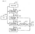
- the facilities include a pressure decrease ratio calculating unit 751, a pressure decrease ratio comparing unit 791, a pressure decrease ratio inferring unit 752, and a pressure decrease ratio notifying unit 771.
- the pressure decrease ratio calculating unit 751 calculates a pressure decrease ratio, at which pressure decreases during surfacing, using a result of timekeeping performed by the timer 68 and a result of measurement performed by the pressure meter 61.
- the pressure decrease ratio comparing unit 791 compares the upper limit of a pressure decrease ratio determined by an upper limit-of-pressure decrease ratio setting unit 76 with a pressure decrease ratio calculated by the pressure decrease ratio calculating unit 751 according to the information of an atmospheric pressure on water measured by the pressure meter 61 before the start of diving or the information of the atmospheric pressure on water entered at the operation unit 5 before the start of diving.
- the pressure decrease ratio inferring unit 752 calculates a difference between a pressure decrease ratio calculated previously by the pressure decrease ratio calculating unit 751 and a pressure decrease ratio calculated currently. The pressure decrease ratio inferring unit 752 then divides the previous pressure decrease ratio by the current pressure decrease ratio to work out a pressure decrease ratio change rate.
- the pressure decrease ratio inferring unit 752 then infers a pressure decrease ratio predicted in several seconds from the pressure decrease ratio change rate.
- the pressure decrease ratio notifying unit 771 gives a warning indicating violation of a specified pressure decrease ratio.
- the pressure decrease ratio notifying unit 771 directly notifies the current pressure decrease ratio or the pressure decrease ratio predicted in several seconds, or notifies a ratio of the current pressure decrease ratio or the pressure decrease ratio predicted in several seconds to the upper limit of a pressure decrease ratio.
- the pressure decrease ratio may be converted into a surfacing speed in consideration of the concentration of seawater or fresh water for a diver's better understanding.
- the upper limit-of-pressure decrease ratio setting unit 76 may set the upper limit of a pressure decrease ratio using a pressure change rate calculated from a current pressure.
- the pressure decrease ratio calculating unit 751 is realized as an arithmetic facility by utilizing the CPU 51, ROM 53, and RAM 54 shown in Fig. 2 .
- the pressure decrease ratio notifying unit 771 is realized as an indicating facility by utilizing the CPU 51, ROM 53, RAM 54, notifier 37, and vibration generator 38, and liquid crystal panel 11.
- the comparing unit 791 compares the upper limit of a pressure decrease ratio, which is associated with each range of atmospheric pressures on the surface, stored in the ROM 53, and set by the upper limit-of-pressure decrease ratio setting unit 76, with a current pressure decrease ratio.
- the pressure decrease ratio notifying unit 771 gives a warning indicating violation of a specified pressure decrease ratio. Specifically, a warning may be indicated on the liquid crystal display panel 11, an alarm sound may be generated by the acoustic notifier 37, or vibrations generated by the vibration generator 38 are propagated to a diver.
- the warning indicating violation of the specified pressure decrease ratio is stopped.
- the pressure decrease ratio notifying unit 771 communicates the information of a pressure decrease ratio, which is calculated by the pressure decrease ratio calculating unit 751, by raising the frequency of an alarm sound, which is generated by the acoustic notifier 37, with an increase in the pressure decrease ratio. Instead of changing the frequency of an alarm sound, the tempo of the alarm sound or the volume thereof may be varied. Moreover, the pressure decrease ratio notifying unit 771 may use the vibration generator 38 to notify a varying pressure decrease ratio by increasing or decreasing the amplitude of vibrations or the tempo thereof. Moreover, the pressure decrease ratio notifying unit 771 may use the display panel 11 to indicate a result of calculation of a tolerance of a current pressure decrease ratio to the upper limit of a pressure decrease ratio.
- the tolerance is calculated using a pressure decrease ratio calculated by the pressure decrease ratio calculating unit 751 and the upper limit of a pressure decrease ratio set by the upper limit-of-pressure decrease ratio setting unit 76.
- graphical indication like the one using a bar graph 118 shown in Fig. 1 is recommended.
- the pressure decrease ratio notifying unit 771 may be realized using the acoustic notifier 37, vibration generator 38, and display panel 11 in combination.
- the diver's information processing device 1 includes a results-of-diving recording unit 78 that stores and preserves in the RAM 54 the results of diving (a date of diving, a diving time, a maximum depth of water, and other various data).
- the results of diving are concerned with one diving action that is thought to start when a depth of water measured by the pressure meter 61 becomes larger than 1.5 m (value used to judge whether diving has started) and end when the depth of water becomes smaller than 1.5 (value used to judge whether diving has been completed).
- the results-of-diving recording unit 78 is realized as a facility using the capabilities of the CPU 51, ROM 53, and RAM 54 shown in Fig. 2 .
- the results-of-diving recording unit 78 records as a result of diving violation of a specified pressure decrease ratio.
- the results-of-diving recording unit 78 measures a diving time according to the result of timekeeping performed by the timer 68 during a period from the instant the depth of water calculated by the pressure meter 61 becomes larger than 1.5 m (value used to judge whether diving has started) to the instant the depth of water becomes smaller than 1.5 m (value used to judge whether diving has been completed). If the diving time is less than 3 minutes , the diving is not treated as one diving action. The results of diving acquired during the diving time are not recorded.
- the results-of-diving recording unit 78 records and preserves up to ten data sets of the results of diving as log data. If the diving time is longer than 3 min, old data is deleted in order of length of a period during which data is preserved. If the results of diving performed for a short period of time, such as, skin diving are recorded, the results of important diving may be deleted.
- the notifying sound generation circuit consists of a booster coil 371, a piezoelectric element buzzer 372, an IC 373, a transistor 374, and a buzzer driving power supply 375. Electricity is supplied from the buzzer driving power supply 375 to the booster coil 371.
- the booster coil 371 in turn boosts the electricity. Consequently, an alternating voltage is applied to the piezoelectric element buzzer 372. Eventually, a notifying sound (alarm sound) is generated.
- An eccentric weight 384 is fixed to a step motor like the one shown in Fig. 12 .
- the step motor is rotated continuously in order to propagate vibrations. Thus, a vibration alarm is given.
- the vibration alarm step motor is composed of a rotor 385, a stator 382a, a stator 382b, a magnetic core 387, and a single-phase driving coil 381.
- a permanent magnet 389 and the eccentric weight 384 are coaxially fixed to the rotation shaft 382 of the rotor 385.
- the permanent magnet 289 is made mainly of a rare earth material, for example, samarium cobalt. Preferably, the permanent magnet 289 is polarized to have at least two poles.
- the eccentric weight 384 is preferably made of a heavy metal in order to improve the effect of vibrations for notification.
- a gold alloy or a tungsten alloy is employed.
- the rotor 385 is locked with two chips of stators 382a and 382b.
- Fig. 14 is an enlarged view of the stators and their surroundings.
- the two chips of stators 382a and 382b are eccentric and opposed to each other, and fixed to the magnetic core 387 with screws 380. Consequently, the stators and magnetic core constitute a magnetic circuit.
- the stators 382a and 382b and magnetic core 387 are made of a material exhibiting a high magnetic permeability, for example, Permalloy in order to attain a high magnetic permeability.
- a single-phase driving coil is formed with the magnetic core 387 as a core.
- a driving circuit for the vibration alarm step motor is, as shown in Fig. 12 , composed of the CPU 51, a steering circuit 386, and a driver circuit 388.
- the CPU 51 provides a driving pulse P1 and thus transmits a signal composed of the driving pulses to the steering circuit 386.
- the driver circuit 388 consists of a PMOS transistor Tr1, a PMOS transistor Tr4, an NMOS transistor Tr2, and an NMOS transistor Tr3.
- control signal C1 is applied to the gate of the PMOS transistor Tr1.
- the control signal C2 is fed to the NMOS transistor Tr2, and the control signal C3 is fed to the NMOS transistor Tr3.
- the control signal C4 is applied to the gate of the PMOS transistor Tr4.
- One terminal of the driving coil 381 is connected to the drains of the PMOS transistor Tr1 and NMOS transistor Tr2.
- the other terminal of the driving coil 381 is connected to the drains of the NMOS transistor Tr3 and PMOS transistor Tr4.
- the control signals C1 to C4 output from the steering circuit 386 are all low.
- the PMOS transistor Tr1 and PMOS transistor Tr4 are turned on.
- a high-voltage supply voltage Vdd is applied to the driving coil 381.
- the stators 382 are magnetized in a first direction, whereby the rotor 385 is rotated.
- the next driving pulse P1 is output.
- the control signals C3 and C4 are driven high and the control signals C1 and C2 are driven low.
- the PMOS transistor Tr1 is turned on, the NMOS transistor Tr2 is turned off, the NMOS transistor Tr3 is turned on, and the PMOS transistor Tr4 is turned off.
- the stators 382 are magnetized in a second direction opposite to the first direction, whereby the rotor 385 is rotated.
- the display surface of the liquid crystal display panel 11 is segmented into nine display fields.
- the nine display fields fall broadly into a display field 11A defined in the center of the display surface, and an annular display field 11B defined on the periphery of the display field 11A.
- the display field 11A and the annular display field 11B defined outside the display field 11A have round shapes respectively.
- the shapes of the display fields 11A and 11B are not limited to the round shapes but may be elliptic shapes, track-like shapes, or polygonal shapes.
- a first display field 111 defined near a position on the display surface comparable to the position of a mark of 12 on a wristwatch is the largest field among all the display fields.
- a current depth of water, a depth-of-water rank into which a depth of water is classified, and a date of diving (log number) are indicated in a diving mode, a surface mode (time instant mode), a planning mode, and a log mode respectively.
- a second display field 112 is defined adjacently to the first display field 111 near a position on the display surface comparable to the position of a mark of 3 on a wristwatch.
- a diving time, a current time instant, a non-decompression diving enabled time, and a diving start time instant are indicated in the diving mode, surface mode (time instant mode), planning mode, and log mode respectively.
- a third display field 113 is defined below the first display field 111 near a position on the display surface comparable to the position of a mark of 6 on a wristwatch.
- a maximum depth of water, an intracorporeal nitrogen discharge time, a safety level, and a maximum depth of water (average depth of water) are indicated in the diving mode, surface mode (time instant mode), planning mode, and log mode respectively.
- a fourth display field 114 is defined adjacently to the third display field 113 near a position on the display surface comparable to the position of the mark of 3 on a wristwatch.
- a non-decompression diving enabled time, a surface pause time, a temperature, and a diving end time are indicated in the diving mode, surface mode (time instant mode), planning mode, and log mode respectively.
- a fifth display field 115 is defined below the third display field 113 near a position on the display surface comparable to the side of the mark of 6 on a wristwatch.
- a power out warning 104 and an altitude rank 103 into which an altitude is classified are indicated.
- a sixth display field 116 defined near the position on the display surface comparable to the position of the mark of 6 on a wristwatch, an amount of intracorporeal nitrogen is indicated graphically.
- a seventh display field 117 is defined adjacently to the sixth display field 116 near the position on the display surface comparable to the position of the mark of 3 on a wristwatch.
- the seventh display field 117 includes a sub-field in which whether nitrogen (inert gas) tends to be absorbed or discharged by a diver who is being decompressed is indicated in the diving mode.
- the seventh display field 117 includes a sub-field in which "SLOW" is displayed, and a sub-field in which "DECO" is displayed.
- “SLOW” is one of pressure decrease ratio violation warning marks and indicates that a pressure decrease ratio is too high
- "DECO” is a warning mark indicating that a diver is being decompressed during diving.
- an eighth display field 118 defined below the seventh display field 117 near the position on the display surface comparable to the position of the mark of 6 on a wristwatch a pressure decrease ratio at which pressure changes during surfacing is graphically indicated in the diving mode.
- Fig. 4 is a functional block diagram for explaining an example of a configuration for calculating a partial pressure of intracorporeal nitrogen (amount of intracorporeal inert gas) in the diver's information processing device 1 of the present example.
- the amount of intracorporeal nitrogen is adopted as an example of a condition for decompression to be calculated.
- Various methods of calculating other various parameters may be adopted.
- a configuration for calculating the amount of intracorporeal nitrogen will be described briefly.
- a method of calculating a condition for decompression occurring during diving, which is employed in the diver's information processing device of the present example has been described in " Dive Computers A Consumer's Guide to History, Theory & Performance" (Watersport Publishing Inc., 1991) written by Ken Loyst et al.
- the diver's information processing device 1 of the present example includes facilities shown in Fig. 4 .
- the facilities are the pressure meter 61, partial pressure-of-respiratory nitrogen calculator 62, partial pressure-of-respiratory nitrogen memory 63, partial pressure-of-intracorporeal nitrogen calculator 64, partial pressure-of-intracorporeal nitrogen memory 65, timer 68, comparator 66, and semi-saturation time selector 67.
- the pressure meter 61 measures a depth of water (hydraulic pressure) or an atmospheric pressure using the pressure sensor 34, amplifier circuit 35, and A/D converter circuit 36 which are shown in Fig. 2 .
- the partial pressure-of-respiratory nitrogen calculator 62 is realized with the capabilities of the CPU 51, ROM 53, and RAM 54 shown in Fig. 2 .
- the partial pressure-of-respiratory nitrogen memory 63 is realized with the RAM 54 shown in Fig. 2 .
- the partial pressure-of-intracorporeal nitrogen calculator 64 is realized with the capabilities of the CPU 51, ROM 53, and RAM 54 shown in Fig. 2 .
- the partial pressure-of-intracorporeal nitrogen memory 65 is realized with the RAM 54 shown in Fig. 2 .
- the timer 68 is realized with the time instant counter 33 shown in Fig. 2 .
- the comparator 66 is realized with the capabilities of the CPU 51, ROM 53, and RAM 54 shown in Fig.
- the semi-saturation time selector 67 is realized with the capabilities of the CPU 51, ROM 53, and RAM 54 shown in Fig. 2 .
- the partial pressure-of-respiratory nitrogen calculator 62, partial pressure-of-intracorporeal nitrogen calculator 64, comparator 66, and semi-saturation selector 67 may be realized as software used in the CPU 51, ROM 53, and RAM 54 shown in Fig. 2 .
- partial pressure-of-respiratory nitrogen calculator 62, partial pressure-of-intracorporeal nitrogen calculator 64, comparator 66, and semi-saturation selector 67 may each be realized with only a logic circuit that is hardware, or a combination of a processing circuit, which includes a logic circuit and a CPU, and software.
- the pressure meter 61 calculates and outputs a hydraulic pressure P(t) that varies with a time t.
- the partial pressure-of-respiratory nitrogen calculator 62 calculates and outputs a partial pressure of respiratory nitrogen PIN2(t) using the hydraulic pressure P(t) output from the pressure meter 61.
- the partial pressure of respiratory nitrogen PIN2(t) is calculated using the hydraulic pressure P(t), which is applied to a diver during diving, according to the expression below.
- PGT(tE) PGT t 0 + PIN 2 t 0 - PGT t 0 ⁇ 1 - exp - k ⁇ t E - T 0 / T H where k denotes a constant experimentally drawn out.
- the comparator 66 compares PIN2(t), which is a result of calculation stored in the partial pressure-of-respiratory nitrogen memory 63, with PGT(t) that is a result of calculation stored in the partial pressure-of-intracorporeal nitrogen memory 65. Consequently, the semi-saturation time selector 67 varies a semi-saturation time TH employed by the partial pressure-of-intracorporeal nitrogen calculator 64.
- the comparator 66 compares PIN2(t0) with PGT(t0).
- PGT t E PGT t 0 + PIN 2 t 0 - PGT t 0 ⁇ 1 - exp - k ⁇ t E - T 0 / T H ⁇ 1
- PGT t E PGT t 0 + PIN 2 t 0 - PGT t 0 ⁇ 1 - exp - k ⁇ t E - T 0 / T H ⁇ 2 where k denotes a constant and TH2 is smaller than TH1.
- the semi-saturation time TH is preferably set to equal (TH2+TH1)/2.
- the time instants (or measurement of t0 and tE) are managed by the timer 68 shown in Fig. 3 .
- a time during which diving can be performed without decompression or a time required after a diver surfaces until an amount of intracorporeal nitrogen returns to a normal level can be calculated based on a current amount of intracorporeal nitrogen. If a diver is notified of these items of information, safety in diving can be improved.
- Fig. 5 shows items to be indicated in the display field 11A alone out of all the display fields on the liquid crystal panel 11.
- the time instant mode ST1 is a mode in which the information processing device 1 is operated when the information processing device 1 is carried with a diver on the land with no switch manipulated and with intracorporeal nitrogen in equilibrium.
- a current date 100, a current time instant 101, and an altitude rank 102 into which an altitude is classified are indicated on the liquid crystal panel 11.
- the altitude rank 102 the altitude of a current place is automatically measured and classified into any of three ranks.
- the current time instant 101 is indicated with a flickering colon. For example, when the liquid crystal display panel 11 is in the state shown in Fig. 5 and Fig. 6 , it is ten past six on December 5th.
- the time instant mode ST1 when the switch A is pressed, the time instant mode ST1 is changed directly to the planning mode ST3.
- the time instant mode ST1 is changed directly to the log mode ST6.
- the switch A is pressed, if the switch B is kept pressed for five seconds with the switch A held down, the time instant mode ST1 is changed to the setting mode ST4.
- the surface mode ST2 is a mode adopted when the information processing device 1 is carried with a diver on the land until forty-eight hours have elapsed since a previous diving action.
- an estimated change in an amount of intracorporeal nitrogen occurring after completion of diving is indicated as shown in Fig. 6 .
- a time required until excess nitrogen having permeated into a body is discharged and intracorporeal nitrogen reaches equilibrium is indicated as an intracorporeal nitrogen discharge time 201.
- the intracorporeal nitrogen discharge time 201 the time required until intracorporeal nitrogen reaches equilibrium is counted down. After the intracorporeal nitrogen discharge time 201 becomes zero hour and zero minutes, no indication is displayed. Moreover, a time having elapsed since completion of diving is indicated as a surface pause time 202. For indicating the surface pause time 202, timekeeping is started with a time instant, at which a depth of water indicated in the diving mode ST5 becomes smaller than 1.5 m, regarded as the end of diving. Timekeeping is continued for forty-eight hours. Thereafter, no indication is displayed. In the information processing device 1, the surface mode ST2 is established on the land until forty-eight hours elapses since completion of diving. Thereafter, the time instant mode ST1 is established.
- the surface mode ST2 is changed directly to the planning mode ST3.
- the surface mode ST2 is changed directly to the log mode ST6.
- the surface mode ST2 is changed to the setting mode ST4.
- the planning mode ST3 is a mode in which an estimated maximum depth of water at which the next diving will be performed and an estimated diving time can be entered.
- this mode as shown in Fig. 7 , the depth-of-water rank 301 into which a depth of water is classified, the non-decompression diving enabled time 302 during which diving can be performed without decompression, the safety level, the altitude rank, and the surface pause time 202 are indicated.
- the intracorporeal nitrogen graph 203 is displayed.
- an indication of a lower rank is sequentially changed to an indication of a higher rank.
- Indications displayed as the depth-of-water rank 301 are 9 m, 12 m, 15 m, 18 m, 21 m, 24 m, 27 m, 30 m, 33 m, 36 m, 39 m, 42 m, 45 m, and 48 m that are switched at intervals of 5 seconds. If the planning mode ST3 is established on behalf of the time instant mode ST1, initial diving is planned for a diver not having excess nitrogen accumulated in his/her body due to past diving. Therefore, the intracorporeal nitrogen graph 203 appears with no mark. When a depth of water is 15 m, the non-decompression diving enabled time 302 is indicated as sixty-six minutes.
- the planning mode ST3 is established on behalf of the surface mode ST2, repeated diving is planned for a diver who has excess nitrogen accumulated in his/her body due to past diving. Consequently, the intracorporeal nitrogen graph 203 appears with four marks.
- the non-decompression diving enabled time 302 is indicated as forty-nine minutes. This signifies that diving can be performed without decompression at depths of water ranging from 12 m to 15 m for less than forty-nine minutes.
- the planning mode ST3 is changed directly to the surface mode ST2. After the depth-of-water rank 301 is indicated as 48 m, the planning mode ST3 is automatically changed to the time instant mode ST1 or surface mode ST2. If no switch is manipulated during a predetermined period, the planning mode ST3 is automatically changed to the surface mode ST2 or time instant mode ST1. This obviates the necessity of manipulating the switches for every change of the planning mode to another mode, and would be convenient. In contrast, when the switch B is pressed, the planning mode ST3 is changed directly to the log mode ST6.
- the setting mode ST4 is a mode for enabling, in addition to setting of the date 100 and current time instant 101, designation of whether warning alarms are turned on or off and setting of a safety level.
- the date 100, a year 106, the current time instant 101, the safety level (not shown), whether the alarms are turned on or off (not shown), and the altitude rank are indicated.
- the safety level can be set to two levels, that is, a level at which normal decompression-related calculation is performed, and a level at which decompression-related calculation is performed on the assumption that a diver travels to a place, of which altitude belongs to an altitude rank higher by one rank, after completion of diving.
- Designation of whether the alarms are turned on or off is a designation of whether various warning alarms should be sounded using the acoustic notifier 37. If the alarms are set to be off, no alarm is sounded. In the diver's information processing device 1 to which a dead battery is fatal, power to be consumed by the alarms can be saved. This would be helpful.
- the setting mode ST4 every time the switch A is pressed, the set items of hours, seconds, minutes, a year, a month, a day, a safety level, and whether the alarms are turned on or off are changed in that order. An indication of each set item is flickered. At this time, when the switch B is pressed, numerals or characters displayed to indicate a set item are changed to another ones. When the switch B is held down, the numerals or characters are changed quickly. When an indication of whether the alarms are turned on or off is flickered, if the switch A is pressed, the setting mode is returned to the surface mode ST2 or time instant mode ST1. If neither the switch A nor switch B is pressed for one to two minutes, the setting mode is automatically returned to the surface mode ST2 or time instant mode ST1.
- the log mode ST6 is a mode in which various kinds of data are stored and presented when a diver dives deeper than a depth of water of 1.5 m with the diving mode ST5 retained for three minutes or more. These kinds of diving data are successively stored as log data in association with each diving. Up to ten log data sets are stored and preserved. If diving is performed more than ten times, old data is deleted in order of length of time for which data is stored. Ten latest diving actions are always stored.
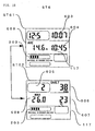
- log data is presented using two screen displays that are switched at intervals of four seconds.
- a date of diving 601 an average depth of water 509
- a diving start time instant 603 a diving end time instant 604
- the altitude rank a diving end time instant 604 indicating an amount of intracorporeal nitrogen detected at the end of diving.
- a log number 605 corresponding to a diving number assigned to a diving action performed on that data
- a maximum depth of water 608 a diving time 606, a water temperature at the maximum depth of water 607, the altitude rank
- the intracorporeal nitrogen graph 203 indicating an amount of intracorporeal nitrogen detected at the end of diving.
- the average depth of water was 14.6 m
- the maximum depth of water was 26.0 m
- the water temperature at the maximum depth of water was 23°C.
- the intracorporeal nitrogen graph 203 appears with four marks, thus indicating that an amount of nitrogen associated with four marks has permeated into the diver's body.
- the log mode ST6 while two screen displays are automatically switched, various kinds of information are presented. Although the display surface of the display panel is limited, a large amount of information can be presented.
- the log mode ST6 every time the switch B is pressed, new data is switched to old data. After the oldest data is presented, the log mode ST6 is changed to the time instant mode ST1 or surface mode ST2. Meanwhile, if the switch B is held down for two or more seconds, the log mode ST6 is changed to the time instant mode ST1 or surface mode ST2. Furthermore, when neither the switch A nor B is pressed for one to two minutes, the log mode ST6 is automatically returned to the surface mode ST2 or time instant mode ST1. This obviates the necessity of manipulating the switches for every change of the log mode to the surface or time instant mode, and would be convenient. In contrast, when the switch A is pressed, the log mode ST6 is changed directly to the planning mode ST3.
- the diving mode ST5 is a mode selected for diving.
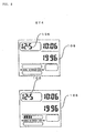
- a non-decompression diving mode ST51 is a mode adopted in order to present information necessary for diving shown in Fig. 9 . Namely, a current depth of water 501, a diving time 502, a maximum depth of water 503, the non-decompression diving enabled time 302, the intracorporeal nitrogen graph 203, and the altitude rank are indicated in the diving mode ST5. For example, when the liquid crystal display panel 11 is in the state shown in Fig. 5 , twelve minutes has elapsed since the start of diving, the depth of water is 16.8 m, and a diver can continue diving without decompression for more forty-two minutes at this depth of water. Moreover, the maximum depth of water having been attained so far is 20.0 m, and a current amount of intracorporeal nitrogen is of a level indicated with four marks displayed as the intracorporeal nitrogen graph 203.
- the pressure decrease ratio calculating unit 751 serving as a pressure decrease ratio monitoring facility calculates a current pressure decrease ratio.
- the pressure decrease ratio notifying unit 771 tells the pressure decrease ratio to a diver in such a manner that the diver can recognize the pressure decrease ratio.
- the pressures in formula (1) are each an absolute pressure that is the sum of an atmospheric pressure and a hydraulic pressure.
- the pressure meter 61 may be used to directly acquire the information of an atmospheric pressure on water. Otherwise, information of an atmospheric pressure is entered using the operation unit 5.
- the upper limit-of-pressure decrease ratio setting unit 76 selects and sets the upper limit of a pressure decrease ratio according to the atmospheric pressure.
- a pressure change rate of a current pressure per unit time may be used to set the upper limit of a pressure decrease ratio. In this case, the step of setting the upper limit of a pressure decrease ratio in association with each atmospheric pressure can be omitted. This results in simplified processing.
- the pressure change rate per min is set to a value that is not equal to or smaller than 0.5.
- the upper limit of a pressure decrease ratio can be set to a value, which will not be equal to a half of the current pressure P(0) within one minute, irrespective of information of an atmospheric pressure or a depth of water. When it says that the pressure should not be halved, it means that the air in a body should not be expanded to be a double.
- dP t dP 0 + ( dP 0 - dP t ⁇ / t ⁇ ⁇ t
- dP(t) denotes a pressure decrease ratio in t seconds (minutes)
- dP(0) denotes a current pressure decrease ratio
- dP(t') denotes a pressure decrease ratio detected t' seconds (minutes) earlier. Consequently, the pressure decrease ratio in t seconds (minutes) can be inferred.
- the expression may be modified so that a time that elapses until the upper limit of a pressure decrease ratio is exceeded can be calculated based on a change rate of the current pressure decrease ratio.
- NAUI National Association of Underwater Instructors
- a surfacing speed should not exceed 18 m per min. For further safety, they recommend that a diver should surface at a speed not exceeding 10 m per min.
- P 0 10 ⁇ exp - H / 8000
- P(0) denotes the atmospheric pressure on water
- H denotes the altitude of the surface of water.
- the atmospheric pressure on water is calculated as 6.7 msw.
- the atmospheric pressure on water is 10 msw.
- the atmospheric pressure at the high altitude of 3200 m is therefore lower by about 3.3 mws.
- msw is adopted as a unit of pressure.
- a distance in seawater in meters is often adopted as a standard unit of pressure.
- the upper limit of a pressure decrease ratio per minute at 0 m above sea level is 10 m
- the upper limit at the height of 3200 m above sea level is 6.7 m that is a critical value.
- the heights above sea level of diving spots are classified into groups that have an equal range.
- the upper limits of a power decrease ratio associated with the groups are listed below. Height above sea level
- the upper limit-of-pressure decrease ratio setting unit 76 determines the upper limit of a pressure decrease ratio.
- the frequency of an alarm sound may be varied or the alarm sound may be combined with a vibratory alarm.
- Pressure decrease ratio msw/min
- Frequency of an alarm sound Hz
- Hz Frequency of an alarm sound
- the upper limit of a pressure decrease ratio is defined based on an atmospheric pressure.
- the upper limit may be defined based on the atmospheric pressure and a depth of water, and the upper limit may be determined in association with each atmospheric pressure and each depth of water.
- a pressure change rate may be determined, and the upper limit of a pressure decrease ratio may be determined based on the pressure change rate. This obviates the necessity of pre-setting the upper limits of a pressure decrease ratio in association with atmospheric pressures on water and depths of water. Processing thus can be simplified.
- a change in a pressure decrease ratio is communicated to a diver by displaying an indication, and the pressure decrease ratio is indicated on the display unit 118 shown in Fig. 1 . If a plurality of divers uses the same diver's information processing devices, when they surface in the same manner, the plurality of diver's information processing devices may generate a sound. Even in this case, the divers are prevented from being at a loss.
- a current time instant indication mode ST52 is established, and the current time instant 101 and current water temperature 504 are indicated while the switch A is held down.
- the liquid crystal display panel 11 is in the state shown in Fig. 9 , it is eighteen past ten and the water temperature is 23°C.
- the switch is manipulated in the diving mode ST5
- the current time instant 101 and current water temperature are indicated for a predetermined period of time.
- the switch is used to change indications. Information a diver wants to know can be presented at a proper timing.
- the diving mode ST5 is automatically changed to the surface mode ST2.
- the results-of-diving recording unit 78 records and preserves in the RAM 54, the results of diving (a date of diving, a diving time, a maximum depth of water, and other various data items). At this time, one diving action is regarded to start when a depth of water becomes 1.5 m or more and end when the depth of water becomes less than 1.5 m. If pressure decrease ratio violation warning is given two or more consecutive times during diving, the fact is also recorded as a result of diving.
- the information processing device 1 of the present example is designed on the assumption that diving is performed without decompression. If decompression becomes necessary during diving, the fact is notified a diver using an alarm sound. Besides, a decompression diving indication mode ST53 described below is established. Specifically, in the decompression diving indication mode ST53, the current depth of water 501, the diving time 502, the intracorporeal nitrogen graph 203, the altitude rank, a decompression pause depth 505, a decompression pause time 506, and a total surfacing time 507 are indicated. When the liquid crystal display panel 11 is in the state shown in Fig. 9 , twenty-four minutes has elapsed since the start of diving and the depth of water is 29.5 m.
- an amount of intracorporeal nitrogen exceeds a permissible maximum value, a diver is in danger, should therefore surface to a depth of water of 3 m while observing a specified pressure decrease ratio of a safe level, and should pause for one minute for decompression. Moreover, an instruction that the diver should take at least five minutes to come up to the surface is presented as the specified pressure decrease ratio of a safe level. Furthermore, the fact that the amount of intracorporeal nitrogen tends to increase is indicated with an upward arrow. Based on the above contents of screen display, the diver surfaces after pausing for decompression. While decompression is under way, the fact that the amount of intracorporeal nitrogen tends to decrease is indicated with a downward arrow 509.
- a diver's information processing device has means for checking a current pressure decrease ratio, giving a warning, and inferring a pressure decrease ratio for preventing the current pressure decrease ratio from being at a dangerous level during diver's surfacing.
Landscapes
- Physics & Mathematics (AREA)
- General Physics & Mathematics (AREA)
- Engineering & Computer Science (AREA)
- Mechanical Engineering (AREA)
- Ocean & Marine Engineering (AREA)
- Electric Clocks (AREA)
- Communication Control (AREA)
- Computer And Data Communications (AREA)
Claims (5)
- Ein Informationsverarbeitungsgerät für einen Taucher (1), umfassend:Druckmessmittel (61);Tauchzeitmessmittel (68) zum Messen einer Tauchzeit;Druckabnahmeverhältnis-Berechnungsmittel (751) zum Berechnen eines Druckabnahmeverhältnisses, bei dem Druck abnimmt während einem Auftauchen, gemäß der Tauchzeit, gemessen durch das Zeitmessmittel (68);Obergrenze-von-Druckabnahmeverhältnis-Einstellmittel (76) zum Einstellen der Obergrenze eines Druckabnahmeverhältnisses; undDruckabnahmeverhältnis-Vergleichsmittel (791) zum Vergleichen der Obergrenze eines Druckabnahmeverhältnisses, eingestellt durch das Obergrenze-von-Druckabnahmeverhältnis-Einstellmittel (76) mit einem gegenwärtigen Druckabnahmeverhältnis, berechnet durch das Druckabnahmeverhältnis-Berechnungsmittel,wobei das Obergrenze-von-Druckabnahmeverhältnis-Einstellmittel (76) die Obergrenze eines Druckabnahmeverhältnisses einstellt, bei dem Druck abnimmt während einem Auftauchen bei einem Tauchen gemäß Information eines atmosphärischen Drucks auf Wasser, in dem ein Tauchen ausgeführt wird.
- Ein Informationsverarbeitungsgerät für einen Taucher nach Anspruch 1, ferner umfassend ein Druckabnahmeverhältnis-Folgerungsmittel (752) zum Ableiten eines Druckabnahmeverhältnisses von einer Änderungsrate zwischen einem gegenwärtig berechneten Druckabnahmeverhältnis und einem Druckabnahmeverhältnis, das vorher berechnet wurde durch das Druckabnahmeverhältnis-Berechnungsmittel (751).
- Ein Informationsverarbeitungsgerät für einen Taucher nach Anspruch 1, wobei das Obergrenze-von-Druckabnahmeverhältnis-Einstellmittel die Obergrenze eines Druckabnahmeverhältnisses einstellt, bei dem ein Druck abnimmt während einem Auftauchen beim Tauchen gemäß einem Druck, der gemessen wird durch das Druckmessmittel, und einer voreingestellten Druckänderungsrate.
- Ein Informationsverarbeitungsgerät für einen Taucher nach einem der Ansprüche 1 bis 3, ferner umfassend ein Druckabnahmeverhältnis-Benachrichtungsmittel (771) zum Benachrichtigen eines gegenwärtigen Druckabnahmeverhältnisses oder zum Ausgeben einer Warnung, wenn es beurteilt wird aus einem Vergleich des gegenwärtigen Druckabnahmeverhältnisses mit der Obergrenze eines Druckabnahmeverhältnisses, dass das gegenwärtigen Druckabnahmeverhältnis die Obergrenze eines Druckabnahmeverhältnisses überschreitet.
- Ein Informationsverarbeitungsgerät für einen Taucher nach einem der Ansprüche 1 bis 4, ferner umfassend ein Obergrenze-von-Druckabnahmeverhältnis-Anzeigemittel zum Anzeigen einer Toleranz hinsichtlich der Obergrenze eines Druckabnahmeverhältnisses.
Applications Claiming Priority (3)
| Application Number | Priority Date | Filing Date | Title |
|---|---|---|---|
| JP25450399 | 1999-09-08 | ||
| JP25450399 | 1999-09-08 | ||
| PCT/JP2000/006074 WO2001018488A1 (en) | 1999-09-08 | 2000-09-06 | Information processing device for diver |
Publications (3)
| Publication Number | Publication Date |
|---|---|
| EP1134547A1 EP1134547A1 (de) | 2001-09-19 |
| EP1134547A4 EP1134547A4 (de) | 2005-03-16 |
| EP1134547B1 true EP1134547B1 (de) | 2008-10-22 |
Family
ID=17265970
Family Applications (1)
| Application Number | Title | Priority Date | Filing Date |
|---|---|---|---|
| EP00956984A Expired - Lifetime EP1134547B1 (de) | 1999-09-08 | 2000-09-06 | Informationsverarbeitungsvorrichtung für taucher |
Country Status (6)
| Country | Link |
|---|---|
| US (1) | US6519548B1 (de) |
| EP (1) | EP1134547B1 (de) |
| JP (1) | JP3478289B2 (de) |
| AT (1) | ATE412165T1 (de) |
| DE (1) | DE60040590D1 (de) |
| WO (1) | WO2001018488A1 (de) |
Cited By (2)
| Publication number | Priority date | Publication date | Assignee | Title |
|---|---|---|---|---|
| RU2688788C1 (ru) * | 2018-06-06 | 2019-05-22 | Федеральное государственное бюджетное военное образовательное учреждение высшего образования Военно-медицинская академия имени С.М. Кирова Министерства обороны Российской Федерации (ВМедА) | Способ определения степени индивидуальной устойчивости водолазов к токсическому действию азота |
| RU2712067C1 (ru) * | 2019-07-15 | 2020-01-24 | Федеральное государственное бюджетное военное образовательное учреждение высшего образования "Военно-медицинская академия имени С.М. Кирова" Министерства обороны Российской Федерации (ВМедА) | Способ определения устойчивости человека к действию высоких парциальных давлений азота по изменению скорости переработки информации в зрительном анализаторе |
Families Citing this family (24)
| Publication number | Priority date | Publication date | Assignee | Title |
|---|---|---|---|---|
| DE69940644D1 (de) * | 1998-12-23 | 2009-05-07 | Asulab Sa | Uhr mit barometer oder höhenanzeige und verfahren zu ihrer herstellung |
| KR20020097356A (ko) * | 2001-06-20 | 2002-12-31 | 현대자동차주식회사 | 멀티 미터의 기압 표시 방법 |
| JP2003143460A (ja) * | 2001-08-24 | 2003-05-16 | Fuji Photo Film Co Ltd | デジタルカメラ |
| US8174436B2 (en) | 2002-07-08 | 2012-05-08 | American Underwater Products, Inc. | Dive computer with global positioning system receiver |
| US9443039B2 (en) | 2002-07-08 | 2016-09-13 | Pelagic Pressure Systems Corp. | Systems and methods for dive computers with remote upload capabilities |
| US7628153B2 (en) * | 2004-02-25 | 2009-12-08 | Kevin William Juergensen | Display integrated vibrating alarm |
| DE602004018455D1 (de) * | 2004-03-22 | 2009-01-29 | Eta Sa Mft Horlogere Suisse | Verfahren zur Detektion des Beginns eines Tauchgangs für Tauchcomputer |
| USD541179S1 (en) * | 2004-12-16 | 2007-04-24 | Suunto Oy | Combined wrist watch, wrist computer and diving computer |
| EP1722285A1 (de) * | 2005-05-10 | 2006-11-15 | ETA SA Manufacture Horlogère Suisse | Tragbares wasserdichtes Gerät, das einen Schallgeber aufweist |
| JP2007182199A (ja) * | 2006-01-10 | 2007-07-19 | Seiko Epson Corp | ダイバーズ用情報処理装置、ダイバーズ用情報処理装置の制御方法および制御プログラム |
| US7797124B2 (en) * | 2006-12-28 | 2010-09-14 | American Underwater Products, Inc. | Dive computer with free dive mode and wireless data transmission |
| DE102012100679B4 (de) * | 2012-01-27 | 2016-02-18 | Michael Feicht | Unterwasserwarnvorrichtung |
| US10518848B2 (en) | 2012-03-28 | 2019-12-31 | Marine Depth Control Engineering, Llc | Smart buoyancy compensation devices |
| US11050142B2 (en) | 2013-03-11 | 2021-06-29 | Suunto Oy | Coupled antenna structure |
| US11059550B2 (en) * | 2013-03-11 | 2021-07-13 | Suunto Oy | Diving computer with coupled antenna and water contact assembly |
| US9304229B2 (en) | 2013-03-14 | 2016-04-05 | SBE Horological Automata, LLC | Recording barometer horological complication |
| US9908599B2 (en) | 2013-05-24 | 2018-03-06 | Shearwater Research Inc. | Heads-up display for displaying a partial pressure of oxygen to a diver |
| US9821893B2 (en) | 2014-10-06 | 2017-11-21 | Pelagic Pressure Systems Corp. | System and methods for configurable dive masks with multiple interfaces |
| USD863083S1 (en) * | 2017-06-28 | 2019-10-15 | Cirsea | Diving computer |
| JP2018072347A (ja) * | 2017-11-15 | 2018-05-10 | カシオ計算機株式会社 | 警告通知装置、電子時計、警告方法およびプログラム |
| TWI798344B (zh) | 2018-02-08 | 2023-04-11 | 芬蘭商順妥公司 | 槽孔模式天線 |
| EP3572886B1 (de) * | 2018-05-23 | 2021-07-14 | The Swatch Group Research and Development Ltd | Armbanduhr, die ein element mit einem beleuchtbaren zeiger umfasst |
| US10921597B2 (en) | 2018-08-22 | 2021-02-16 | Shearwater Research Inc. | Heads-up display for use in underwater applications |
| CN116101459A (zh) * | 2023-01-10 | 2023-05-12 | 无锡探海电子科技有限公司 | 一种基于空气循环潜水的自适应潜水减压方法 |
Family Cites Families (12)
| Publication number | Priority date | Publication date | Assignee | Title |
|---|---|---|---|---|
| US3992948A (en) * | 1974-09-27 | 1976-11-23 | Antonio Nicholas F D | Diver information system |
| JPS58193466A (ja) * | 1982-05-07 | 1983-11-11 | Citizen Watch Co Ltd | ダイバ−用アラ−ム装置 |
| EP0195636B1 (de) * | 1985-03-19 | 1991-07-10 | Citizen Watch Co. Ltd. | Armbanduhr mit Druckmessfühler |
| US4835716A (en) | 1986-02-05 | 1989-05-30 | Casio Computer Co., Ltd. | Compact measuring apparatus capable of measuring two different data with a single pressure sensor |
| JPS62215889A (ja) * | 1986-03-18 | 1987-09-22 | Citizen Watch Co Ltd | 水深計付電子時計 |
| JPS63174093U (de) * | 1986-11-29 | 1988-11-11 | ||
| JPH067306B2 (ja) | 1987-01-14 | 1994-01-26 | 株式会社ピーエフユー | 表示制御回路 |
| JP2928809B2 (ja) * | 1990-03-15 | 1999-08-03 | カシオ計算機株式会社 | 電子式水深計 |
| JP3293245B2 (ja) * | 1993-06-30 | 2002-06-17 | カシオ計算機株式会社 | 減圧情報表示装置 |
| KR100246175B1 (ko) | 1994-11-22 | 2000-03-15 | 셴왕빙 | 수소첨가 탈금속 촉매 및 그 제조 방법 |
| JP3520391B2 (ja) | 1997-03-10 | 2004-04-19 | セイコーエプソン株式会社 | ダイバーズ用情報処理装置 |
| JP3520400B2 (ja) | 1997-09-03 | 2004-04-19 | セイコーエプソン株式会社 | ダイバーズ用情報表示装置 |
-
2000
- 2000-09-06 WO PCT/JP2000/006074 patent/WO2001018488A1/ja not_active Ceased
- 2000-09-06 EP EP00956984A patent/EP1134547B1/de not_active Expired - Lifetime
- 2000-09-06 DE DE60040590T patent/DE60040590D1/de not_active Expired - Fee Related
- 2000-09-06 JP JP2001522032A patent/JP3478289B2/ja not_active Expired - Fee Related
- 2000-09-06 US US09/831,181 patent/US6519548B1/en not_active Expired - Lifetime
- 2000-09-06 AT AT00956984T patent/ATE412165T1/de not_active IP Right Cessation
Cited By (2)
| Publication number | Priority date | Publication date | Assignee | Title |
|---|---|---|---|---|
| RU2688788C1 (ru) * | 2018-06-06 | 2019-05-22 | Федеральное государственное бюджетное военное образовательное учреждение высшего образования Военно-медицинская академия имени С.М. Кирова Министерства обороны Российской Федерации (ВМедА) | Способ определения степени индивидуальной устойчивости водолазов к токсическому действию азота |
| RU2712067C1 (ru) * | 2019-07-15 | 2020-01-24 | Федеральное государственное бюджетное военное образовательное учреждение высшего образования "Военно-медицинская академия имени С.М. Кирова" Министерства обороны Российской Федерации (ВМедА) | Способ определения устойчивости человека к действию высоких парциальных давлений азота по изменению скорости переработки информации в зрительном анализаторе |
Also Published As
| Publication number | Publication date |
|---|---|
| ATE412165T1 (de) | 2008-11-15 |
| WO2001018488A1 (en) | 2001-03-15 |
| DE60040590D1 (de) | 2008-12-04 |
| EP1134547A4 (de) | 2005-03-16 |
| US6519548B1 (en) | 2003-02-11 |
| EP1134547A1 (de) | 2001-09-19 |
| JP3478289B2 (ja) | 2003-12-15 |
Similar Documents
| Publication | Publication Date | Title |
|---|---|---|
| US6519548B1 (en) | Information processing device for diver | |
| JPWO2001018488A1 (ja) | ダイバーズ用情報処理装置 | |
| US7144198B2 (en) | Diver information processing apparatus and method of controlling same | |
| TWI324712B (en) | Electronic diving watch with analog display | |
| TWI274234B (en) | Electronic diving watch with analog display | |
| JP3520400B2 (ja) | ダイバーズ用情報表示装置 | |
| JP3945499B2 (ja) | ダイバーズ用情報処理装置、ダイバーズ用情報処理装置の制御方法、制御プログラム及び記録媒体 | |
| JP3888061B2 (ja) | ダイバーズ用情報処理装置およびダイバーズ用情報処理装置の制御方法 | |
| JP3520391B2 (ja) | ダイバーズ用情報処理装置 | |
| JP3794399B2 (ja) | ダイバーズ用情報処理装置 | |
| JP3520395B2 (ja) | ダイバー用個別安全情報報知装置 | |
| JP3520394B2 (ja) | ダイバーズ用情報処理装置 | |
| JP3968965B2 (ja) | ダイバーズ用情報処理装置およびダイバーズ用情報処理装置の制御方法 | |
| JP3473333B2 (ja) | ダイバーズ用情報処理装置 | |
| JP4453413B2 (ja) | 生体情報監視装置、生体情報監視装置の制御方法、制御プログラムおよび記録媒体 | |
| JP3473334B2 (ja) | ダイバーズ用情報処理装置 | |
| JPWO2000059779A1 (ja) | ダイバーズ用情報処理装置およびダイバーズ用情報処理装置の制御方法 | |
| JP3520398B2 (ja) | ダイバーズ用情報処理装置 | |
| JPH10319150A (ja) | 情報処理装置 | |
| JP2003200888A (ja) | 情報処理装置、情報処理方法、プログラム及び記録媒体 | |
| JP3520397B2 (ja) | ダイバーズ用情報処理装置 | |
| JP3520390B2 (ja) | ダイバーズ用の情報表示装置 | |
| JP3901145B2 (ja) | ダイバーズ用の個別安全情報報知装置 | |
| JP3520421B2 (ja) | ダイバーズ用情報処理装置 | |
| JP2005088685A (ja) | ダイバーズ用情報処理装置、ダイバーズ用情報処理装置の制御方法、制御プログラムおよび記録媒体 |
Legal Events
| Date | Code | Title | Description |
|---|---|---|---|
| PUAI | Public reference made under article 153(3) epc to a published international application that has entered the european phase |
Free format text: ORIGINAL CODE: 0009012 |
|
| 17P | Request for examination filed |
Effective date: 20010430 |
|
| AK | Designated contracting states |
Kind code of ref document: A1 Designated state(s): AT BE CH CY DE DK ES FI FR GB GR IE IT LI LU MC NL PT SE |
|
| AX | Request for extension of the european patent |
Free format text: AL;LT;LV;MK;RO;SI |
|
| RBV | Designated contracting states (corrected) |
Designated state(s): AT CH DE FI IT LI |
|
| A4 | Supplementary search report drawn up and despatched |
Effective date: 20050201 |
|
| GRAP | Despatch of communication of intention to grant a patent |
Free format text: ORIGINAL CODE: EPIDOSNIGR1 |
|
| GRAS | Grant fee paid |
Free format text: ORIGINAL CODE: EPIDOSNIGR3 |
|
| GRAA | (expected) grant |
Free format text: ORIGINAL CODE: 0009210 |
|
| AK | Designated contracting states |
Kind code of ref document: B1 Designated state(s): AT CH DE FI IT LI |
|
| REG | Reference to a national code |
Ref country code: CH Ref legal event code: EP |
|
| REF | Corresponds to: |
Ref document number: 60040590 Country of ref document: DE Date of ref document: 20081204 Kind code of ref document: P |
|
| PG25 | Lapsed in a contracting state [announced via postgrant information from national office to epo] |
Ref country code: AT Free format text: LAPSE BECAUSE OF FAILURE TO SUBMIT A TRANSLATION OF THE DESCRIPTION OR TO PAY THE FEE WITHIN THE PRESCRIBED TIME-LIMIT Effective date: 20081022 |
|
| PG25 | Lapsed in a contracting state [announced via postgrant information from national office to epo] |
Ref country code: FI Free format text: LAPSE BECAUSE OF FAILURE TO SUBMIT A TRANSLATION OF THE DESCRIPTION OR TO PAY THE FEE WITHIN THE PRESCRIBED TIME-LIMIT Effective date: 20081022 |
|
| PLBE | No opposition filed within time limit |
Free format text: ORIGINAL CODE: 0009261 |
|
| STAA | Information on the status of an ep patent application or granted ep patent |
Free format text: STATUS: NO OPPOSITION FILED WITHIN TIME LIMIT |
|
| 26N | No opposition filed |
Effective date: 20090723 |
|
| REG | Reference to a national code |
Ref country code: CH Ref legal event code: PL |
|
| PG25 | Lapsed in a contracting state [announced via postgrant information from national office to epo] |
Ref country code: DE Free format text: LAPSE BECAUSE OF NON-PAYMENT OF DUE FEES Effective date: 20100401 |
|
| PG25 | Lapsed in a contracting state [announced via postgrant information from national office to epo] |
Ref country code: LI Free format text: LAPSE BECAUSE OF NON-PAYMENT OF DUE FEES Effective date: 20090930 Ref country code: CH Free format text: LAPSE BECAUSE OF NON-PAYMENT OF DUE FEES Effective date: 20090930 |
|
| PGFP | Annual fee paid to national office [announced via postgrant information from national office to epo] |
Ref country code: IT Payment date: 20120914 Year of fee payment: 13 |
|
| PG25 | Lapsed in a contracting state [announced via postgrant information from national office to epo] |
Ref country code: IT Free format text: LAPSE BECAUSE OF NON-PAYMENT OF DUE FEES Effective date: 20130906 |