EP1131997B1 - Konstruktion mit Vorrichtung zum Melken von Tieren - Google Patents
Konstruktion mit Vorrichtung zum Melken von Tieren Download PDFInfo
- Publication number
- EP1131997B1 EP1131997B1 EP01202454A EP01202454A EP1131997B1 EP 1131997 B1 EP1131997 B1 EP 1131997B1 EP 01202454 A EP01202454 A EP 01202454A EP 01202454 A EP01202454 A EP 01202454A EP 1131997 B1 EP1131997 B1 EP 1131997B1
- Authority
- EP
- European Patent Office
- Prior art keywords
- animal
- milk
- milking
- computer
- implement
- Prior art date
- Legal status (The legal status is an assumption and is not a legal conclusion. Google has not performed a legal analysis and makes no representation as to the accuracy of the status listed.)
- Revoked
Links
- 241001465754 Metazoa Species 0.000 title claims abstract description 109
- 238000010276 construction Methods 0.000 title claims abstract description 41
- 239000008267 milk Substances 0.000 claims description 82
- 235000013336 milk Nutrition 0.000 claims description 82
- 210000004080 milk Anatomy 0.000 claims description 82
- 210000002445 nipple Anatomy 0.000 claims description 61
- 230000000750 progressive effect Effects 0.000 claims description 2
- 238000005303 weighing Methods 0.000 claims description 2
- 230000003213 activating effect Effects 0.000 claims 1
- 241000283690 Bos taurus Species 0.000 abstract description 5
- 230000010349 pulsation Effects 0.000 description 4
- 210000000481 breast Anatomy 0.000 description 3
- 230000001419 dependent effect Effects 0.000 description 2
- 239000012141 concentrate Substances 0.000 description 1
- 235000013365 dairy product Nutrition 0.000 description 1
- 230000003467 diminishing effect Effects 0.000 description 1
- 230000000694 effects Effects 0.000 description 1
- 230000002349 favourable effect Effects 0.000 description 1
- 238000004519 manufacturing process Methods 0.000 description 1
- 230000033764 rhythmic process Effects 0.000 description 1
Images



Classifications
-
- A—HUMAN NECESSITIES
- A01—AGRICULTURE; FORESTRY; ANIMAL HUSBANDRY; HUNTING; TRAPPING; FISHING
- A01J—MANUFACTURE OF DAIRY PRODUCTS
- A01J5/00—Milking machines or devices
- A01J5/017—Automatic attaching or detaching of clusters
- A01J5/0175—Attaching of clusters
Definitions
- the present invention relates to a construction including at least one implement for automatically milking animals, according to the preamble of claim 1. According to the invention such a construction comprises the characterizing features of claim 1. Embodiments are disclosed in claims 2 to 11.
- Such a construction is known from e.g. European Patent application No. 0091892.
- an animal is not automatically milked within a predetermined time span.
- a drawback of this construction is that a certain frequency or rhythm of milkings is imposed on the animals to a relatively extreme extent.
- the frequency at which each of the animals will be milked is dependent of a characteristic of the animals.
- the animals are thus in a better position to pursue a frequency on their own, because the amount of milk being developed in an animal's udder as time lapses has a different value regarding each animal.
- one animal e.g. a high-yield animal, can be milked once again earlier than another one having a lower yield.
- the milking robot is not in use permanently, animals can enter the milk box without being milked there. In that case such an animal can be given some fodder (concentrate).
- the moment fodder is supplied to a specific animal can be recorded in the computer and may be relevant for the decision whether the animal will be milked or not when it enters the milk box-the next time.
- the invention further relates to a construction including at least one implement for automatically milking animals, comprising a computer, at least one milk box arranged for the milking of an animal and at least one milking robot for applying teat cups to the teats of the animal and for milking the animal, which implement includes means, co-operating with the computer, for identifying an animal that has arrived at the implement, characterized in that the implement is constructed in such a way that it is suitable for
- the invention further relates to a construction including at least one implement for automatically milking animals, comprising a computer, at least one milk box arranged for milking an animal and at least one milking robot for applying teat cups to the teats, which implement includes at least one computer for identifying an animal that has arrived at the implement, characterized in that the computer is able to calculate the point of time from which an animal is allowed to enter the milk box and that the robot will be activated by a signal supplied by the computer, which signal is derived from an amount of the fodder eaten by said animal, whereby volume means or weighing means may supply this data to the computer.
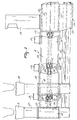
- FIG 1 is a plan view of a milk box 1. which includes a railing 2 and at one side is provided with an entrance door 3 and an exit door 4. A feed trough 5 is fastened to the railing 2 at the leading side of the milk box 1. At the side facing the entrance door and the exit door there is a milking robot 6.
- the milking robot 6 includes a robot arm 7, to whose end teat cups 9 and 10 are connected with the aid of two pivotal arm constructions 8.
- This robot arm 7 is assembled from a first portion 11 which is arranged such at the side of the milk box that it is movable in the longitudinal direction of the milk box 1, a second portion 12 which is rotatable with respect to the first portion 11 about an upwardly directed shaft 13, and a third portion 14 which is rigidly connected to the second portion 12 at a substantially square angle.
- the robot arm 7 can be moved upwards as an integral whole by means of a (non-shown) cylinder. Also moving the robot arm 7 in the longitudinal direction of the milk box 1 and rotating the second robot arm portion 12 about the shaft 13 is effected with the aid of (non-shown) cylinders. These cylinders may be either hydraulic, pneumatic or electromechanical ones.
- a detector 15. e.g.
- a laser detector is accommodated on the third robot arm portion 14, with the aid of which detector the position of the teats of an animal to be milked is determined.
- the pivotal arm constructions 8, at the end of each of which a teat cup 9 and 10 is fitted, are pivotally connected to the end of the third robot arm portion 14.
- a collar including a transponder 16 which is part of a (non-shown) cow identification system, is provided around the neck of the cow, which transponder co-operates with a sensor which may be placed near the feed trough 5 and is in connection with the computer of the system.
- FIGS 2 and 3 are a detailed representation of the end of the robot arm 7 with the pivotal constructions 8.
- the second portion 12 of the robot arm 7 consists of a first box-like beam and a second box-like beam disposed thereunder.
- the milk tubes 19 and the pulsation tubes 20 of the teat cups 9 and 10 are stored in the second box-like beam.
- this third robot arm portion 14 includes a first box-like beam 21 and, arranged thereunder, a second box-like beam 22, these box-like beams 21 and 22 being in connection with the box-like beams of the second robot arm portion 12.
- the milk tubes 19 and the pulsation tubes 20 extend through the lower box-like beam 22.
- the laser detector 15 is disposed pivotabty or rotatably on the third robot arm portion 14.
- a holder 23 is secured to the end of the third robot arm portion 14, in which holder the two pivotal arm constructions 8 are accommodated such that they are rotatable about predominantly vertically extending pivot shafts.
- the pivotal arm constructions 8 can be rotated with respect to the holder 23 with the aid of electric motors 24, which are in the form of stepping motors.
- Each of the two pivotal arm constructions 8 includes four pivotal arms 25, 26, 27 and 28.
- the pivotal arms 25 are rotatable in a predominantly horizontal plane with respect to the third robot arm portion 14 with the aid of the stepping motors 24.
- the pivotal arms 26 are rotatable in a predominantly horizontal plane with respect to the arms 25 with the aid of electric motors, more specifically stepping motors 29.
- the arms 27 and 28 are both capable of rotating in a predominantly horizontal plane relative to the arms 26 with the aid of electric motors, more specifically stepping motors 30 and 31, whose shafts are in alignment.
- the stepping motors 24, 29, 30 and 31 are disposed in the pivot points of the pivotal arm constructions 8, with the aid of which the teat cups 9 and 10 have been coupled to the robot arm 7.
- Figure 6 shows four of such configurations.
- the robot arm 7 and consequently the detector 15 can always be placed in such a manner under the animal that by operating the stepping motors 24, 29, 30 and 31 the teat cups 9 and 10 can be moved to under the teats of the animal to be milked, so that they can be connected by an upward motion of the robot arm 7 and by a vacuum produced in the teat cups.
- the robot arm 7 can be moved downwardly and slightly forwardly.
- the teat cups 9 and 10 connected to the teats remain in this situation in connection with the robot arm 7 by means of a flexible pulling element 32, e.g. a cable or cord.
- this pulling element 32 is connected to a teat cup 9, 10 and the other end to a cylinder accommodated in the third robot arm portion 14, which cylinder may be a pneumatic, hydraulic or electromechanical one.
- the cylinders provided for all four teat cups are denoted in Figures 2 and 5 by reference numeral 33.
- the teat cups 9 and 10 are in the state in which they are not connected to the teats of an animal, they are pulled by the cylinders 33 and the pulling element 32 up against the end of the respective pivotal arms 27 and 28.
- the cylinders 33 are released, so that the robot arm 7 can be moved; the teat cups continue to be freely movable with respect to the robot arm 7.
- the pulling element 32 must be threaded along a plurality of pulleys near the pivot points between the pivotal arms relative to each other and of the pivotal arms 25 and the third robot arm portion 14.
- a set of pulleys for each of the two pulling elements 32, by means of which a teat cup 9 and a teat cup 10 are connected to two cylinders 33 located one above the other inside the third robot arm portion 14.
- these sets of pulleys are located one above the other.
- a set of pulleys includes one pulley 34 arranged near the pivot point between a pivotal arm construction 8 and the third robot arm portion 14, a pair of pulleys 35 near the pivot point between the pivotal arms 25 and 26 and a pair of pulleys 36 near the pivot point between the pivotal arm 26 on the one hand and the respective pivotal arms 27 and 28 on the other hand.
- the pulling element 32 By successively passing a pulling element 32 from its point of connection at a teat cup between two pulleys 36 and two pulleys 35 and thereafter around a pulley 34 to the point of connection at the relevant cylinder 33, the pulling element 32 is accommodated in such a manner in the pivotal arm construction 8 that the freedom of motion of the teat cups relative to the robot arm 7 continues to be ensured to the best possible extent, when these cups are moved in predetermined configurations to under the teats of an animal. In particular, various configurations, such as those shown in Figure 6, can be obtained without any difficulties.
- the points of connection of the pulling elements 32 at the operating cylinders 33 are located at that side of the third robot arm portion 14 that is remote from the pivotal arm constructions 8.
- Each of the pulling elements extends from a teat cup between pairs of pulleys 36 and 35 and along a pulley 34 through the entire third robot arm portion 14 to the rear side thereof and from there via a pulley 37 to a pulley 38 disposed at the rear side of the cylinder and from there to the rear wall of the third robot arm portion 14.
- the teat cups are connected to the pivotal arm constructions 8 capably of rotating freely about their own longitudinal axis. As is shown in Figure 4. this is effected by disposing a sleeve 40 around the exterior housing 39 of the teat cups. The pulling element 32 then acts on the sleeve 40. Because of the capability of the teat cup to rotate freely in the sleeve 40, the milk and/or pulsation tubes allow the pivotal arms to move unimpededly in a pivotal arm construction.
- the sleeve 40 is provided with a bulging portion 41. which co-operates with a seat 42 in the end of a pivotal arm 27 and 28. respectively.
- the invention relates to a milking implement for automatically milking animals, as described before.
- the entrance door 3 and the exit door 4 may be in connection with a dwelling area for animals, such as a cowshed or pasture field.
- the computer is capable of determining the amount of milk produced during each milking of each animal and of recording it, together with the respective point of time of milking, into an electronic memory.
- the milking implement also includes an identification element or sensor, which communicates with the computer, enabling an animal to be identified. In the present embodiment, this sensor is provided in the milk box near the feed trough 5. However, the sensor may equally well be provided outside the milk box for the implementation of a pre-selection on the admission of the animals to the milk box.
- the present embodiment makes use of the known per se identification system, wherein the sensor operates in conjunction with the transponder 16 carried perrnanently by each of the animals.
- the entrance door 3 and the exit door 4 of the milk box are automatically control-lable through the computer.
- the entrance door 3 In the initial position, the entrance door 3 is open and it is closed when the presence of an animal has been established automatically.
- the computer records the actual time as the point of time at which the animal reports herself in the milking implement.
- the amount of milk given in each case, and on the basis of the point of time, as determined by the computer, at which an animal present has been identified it is then determined by the computer what is the expected amount of milk to be given by that animal.
- the computer derives from the recorded data what is the average obvious development of milk or milk yield per unit of time of the relevant animal, expressed in litres/hr, and how much is the length of time between the instant of identification and the latest milking of the animal present. Then, the product of the average milk development in the animal per unit of time and said length of time is the milk yield to be expected. If the milk yield to be expected is higher than a base value to be set, e.g. amounting to six litres, the computer activates the milking robot to milk the animal. When the milking of the animal has been completed or when the amount of milk to be expected does not exceed the base value, the exit door 4 is opened through the computer, so that the animal, whether or not being automatically driven off, leaves the milk box. The amount of milk produced by an animal will be the base on which the computer will decide if the animal will be milked again, when it comes to the milk box.
- a base value to be set e.g. amounting to six litres
- the value of the average milk development per unit of time of each in-dividual animal is determined automatically by means of a progressive average derived from the recorded data per animal.
- a calculation is made for this purpose on the basis of a number, ten in the present embodiment, of such record entries conceming previous milkings of the animal.
- the milk yield of the set number of milkings is summed and the sum is divided by the difference in time between the instant of the last milking recorded and that of the milking preceding the final milking of the set number of milkings to be included in the calculation.
- a buffer area comprises a sensor communicating with the computer for identifying an animal present therein, an exit to be released through the computer and giving access to the area for moving about freely in a cowhouse or pasture field, and a similar exit giving access to the milk box.
- the animal present in the buffer area is led into the said dwelling area if the milk yield to be expected does not exceed the base value, whereas it is led into the milk box if the milk yield to be expected exceeds the base value.
- identification in the milk box 1 is not required any more and it is possible to proceed to the milking of the animal immediately.
- a simpler but less elegant pre-selection can also be effected by simply providing an identification sensor near the entrance door 3 of the milk box 1. The entrance door 3 is then not opened until there is reported an animal which is allowed to be milked on account of the described criterion. Animals which are not to be milked under the criterion of the invention will disappear of their own account or will be pushed away from the entrance door 3 by other animals.
- the embodiments set forth hereinbefore have the advantage that the decision whether or not a reporting animal will be milked is made by means of a condition which, in a simple manner, plays along with the production feature of each of the animals.
- the invention leads to an increase in the milk yield per day, especially for high-yield animals.
- the construction set forth may also be adopted e.g. in a milking implement having a plurality of milk boxes or a plurality of milking robots, while the number of selection areas, too, may not be limitative to the application of the invention.
Landscapes
- Life Sciences & Earth Sciences (AREA)
- Animal Husbandry (AREA)
- Environmental Sciences (AREA)
- Orthopedics, Nursing, And Contraception (AREA)
- External Artificial Organs (AREA)
- Feeding And Watering For Cattle Raising And Animal Husbandry (AREA)
- Catching Or Destruction (AREA)
- Toys (AREA)
- Manipulator (AREA)
Claims (11)
- Anlage mit mindestens einer Vorrichtung zum automatischen Melken von Tieren, die einen Computer, mindestens eine zum Melken eines Tieres geeignete Melkbox und mindestens einen Melkroboter zum Anschließen von Zitzenbechern an die Zitzen umfaßt, wobei die Vorrichtung mindestens einen Computer zum Identifizieren eines Tieres aufweist, das sich in der Vorrichtung einfindet,
dadurch gekennzeichnet, daß der Computer mit einem Programm versehen ist, mittels dessen die Vorrichtung geeignet ist,- die von einem Tier während des Melkens gelieferte Milchmenge aufzuzeichnen,- auf der Basis dieser Daten die voraussichtliche Milchleistung des Tieres dadurch zu berechnen, daß die Milchmenge berechnet wird, die zwischen dem Zeitpunkt des Sicheinfindens und dem eines vorhergehenden Melkdurchganges des in der Melkbox befindlichen Tieres geliefert wurde, und- Aktivieren des Melkroboters, falls die voraussichtliche Milchleistung des Tieres einen Basiswert überschreitet. - Anlage nach Anspruch 1,
dadurch gekennzeichnet, daß die Melkbox mit einem Tieridentifikationssensor versehen ist, der ein Tieridentifikationssignal an den Computer gibt, anhand dessen der Computer automatisch den Eingang der Melkbox freigeben kann. - Anlage nach Anspruch 1 oder 2,
dadurch gekennzeichnet, daß der Computer nach der Identifizierung eines Tieres durch den Computer den aktuellen Zeitpunkt als den Zeitpunkt aufzeichnet, zu dem das Tier sich in der Melkvorrichtung einfindet. - Anlage nach Anspruch 3,
dadurch gekennzeichnet, daß auf der Basis der aufgezeichneten historischen Daten des betreffenden Tieres bezüglich der Zeiten von vorhergehenden Melkdurchgängen und der jeweils gelieferten Milchmenge sowie auf der Basis des von dem Computer ermittelten Zeitpunktes, zu dem das anwesende Tier identifiziert worden ist, von dem Computer ermittelt wird, welche voraussichtliche Milchmenge von diesem Tier geliefert werden wird. - Anlage nach Anspruch 4,
dadurch gekennzeichnet, daß der Computer von den aufgezeichneten Daten ableitet, welches die durchschnittliche wahrscheinliche Milchentwicklung oder Milchleistung pro Zeiteinheit des betreffenden Tieres ist, ausgedrückt in Liter/Stunde, und wie groß der Zeitraum zwischen dem Zeitpunkt der Identifizierung und dem letzten Melken des Tieres ist. - Anlage nach Anspruch 5,
dadurch gekennzeichnet, daß das Produkt aus der durchschnittlichen Milchentwicklung in dem Tier pro Zeiteinheit und dem Zeitraum die zu erwartende Milchleistung ist. - Anlage nach Anspruch 4, 5 oder 6,
dadurch gekennzeichnet, daß der Wert der durchschnittlichen Milchentwicklung pro Zeiteinheit jedes einzelnen Tieres automatisch mit Hilfe eines dynamischen Mittelwertes ermittelt wird, der von den für jedes Tiere aufgezeichneten Daten abgeleitet wird. - Anlage nach Anspruch 7,
dadurch gekennzeichnet, daß beim Identifizieren des Tieres in der Melkbox zu diesem Zweck jedesmal eine Berechnung auf der Basis einer Anzahl, z. B. zehn, solcher Aufzeichnungen über vorhergehende Melkdurchgänge des Tieres durchgeführt wird. - Anlage nach Anspruch 8,
dadurch gekennzeichnet, daß die Milchleistung der eingestellten Anzahl summiert wird und die Summe durch die Zeitdifferenz zwischen dem Zeitpunkt des letzten aufgezeichneten Melkdurchganges und dem Zeitpunkt des Melkdurchganges, der dem letzten Melkdurchgang der eingestellten Anzahl von Melkdurchgängen vorausgegangen ist, geteilt wird, um dies in die Berechnung aufzunehmen. - Anlage mit mindestens einer Vorrichtung zum automatischen Melken von Tieren, die einen Computer, mindestens eine zum Melken eines Tieres geeignete Melkbox und mindestens einen Melkroboter zum Anschließen von Zitzenbechern an die Zitzen des Tieres und zum Melken des Tieres umfaßt, wobei die Vorrichtung eine mit dem Computer zusammenwirkende Vorrichtung zum Identifizieren eines Tieres aufweist, das sich in der Vorrichtung einfindet,
dadurch gekennzeichnet, daß die Vorrichtung derart konstruiert ist, daß sie geeignet ist,- die innerhalb eines vorgegebenen Zeitraumes, z. B. innerhalb der letzten vierundzwanzig Stunden, produzierte Milchmenge aufzuzeichnen,- auf der Basis dieser Daten die voraussichtliche Milchleistung zu berechnen,- vorzugsweise solche Tiere zur Melkbox zuzulassen, die eine voraussichtliche Milchleistung aufweisen, welche die durchschnittliche Milchleistung der Tiere um ein gewisses Maß übersteigt. - Anlage mit mindestens einer Vorrichtung zum automatischen Melken von Tieren, die einen Computer, mindestens eine zum Melken eines Tieres geeignete Melkbox und mindestens einen Melkroboter zum Anschließen von Zitzenbechern an die Zitzen umfaßt, wobei die Vorrichtung mindestens einen Computer zum Identifizieren eines Tieres aufweist, das sich in der Vorrichtung eingefunden hat,
dadurch gekennzeichnet, daß der Computer den Zeitpunkt berechnen kann, zu dem ein Tier die Melkbox betreten darf, und daß der Roboter durch ein von dem Computer geliefertes Signal aktiviert wird, das von einer von dem Tier verzehrten Futtermenge abgeleitet ist, wobei diese Daten durch eine Volumenvorrichtung oder eine Wiegevorrichtung an den Computer geliefert werden können.
Priority Applications (1)
| Application Number | Priority Date | Filing Date | Title |
|---|---|---|---|
| EP06075719A EP1679000A3 (de) | 1994-03-25 | 1995-03-20 | Konstruktion mit einem Gerät zum automatischen Melken von Tieren |
Applications Claiming Priority (5)
| Application Number | Priority Date | Filing Date | Title |
|---|---|---|---|
| NL9400471 | 1994-03-25 | ||
| NL9400471A NL9400471A (nl) | 1994-03-25 | 1994-03-25 | Constructie met een inrichting voor het melken van dieren. |
| NL9400495 | 1994-03-29 | ||
| NL9400495A NL9400495A (nl) | 1994-03-29 | 1994-03-29 | Werkwijze en inrichting voor het automatisch melken van dieren. |
| EP95912499A EP0700245B1 (de) | 1994-03-25 | 1995-03-20 | Konstruktion mit einem gerät zum melken von tieren |
Related Parent Applications (1)
| Application Number | Title | Priority Date | Filing Date |
|---|---|---|---|
| EP95912499A Division EP0700245B1 (de) | 1994-03-25 | 1995-03-20 | Konstruktion mit einem gerät zum melken von tieren |
Related Child Applications (1)
| Application Number | Title | Priority Date | Filing Date |
|---|---|---|---|
| EP06075719A Division EP1679000A3 (de) | 1994-03-25 | 1995-03-20 | Konstruktion mit einem Gerät zum automatischen Melken von Tieren |
Publications (3)
| Publication Number | Publication Date |
|---|---|
| EP1131997A2 EP1131997A2 (de) | 2001-09-12 |
| EP1131997A3 EP1131997A3 (de) | 2003-03-19 |
| EP1131997B1 true EP1131997B1 (de) | 2006-07-12 |
Family
ID=26647198
Family Applications (3)
| Application Number | Title | Priority Date | Filing Date |
|---|---|---|---|
| EP95912499A Expired - Lifetime EP0700245B1 (de) | 1994-03-25 | 1995-03-20 | Konstruktion mit einem gerät zum melken von tieren |
| EP01202454A Revoked EP1131997B1 (de) | 1994-03-25 | 1995-03-20 | Konstruktion mit Vorrichtung zum Melken von Tieren |
| EP06075719A Withdrawn EP1679000A3 (de) | 1994-03-25 | 1995-03-20 | Konstruktion mit einem Gerät zum automatischen Melken von Tieren |
Family Applications Before (1)
| Application Number | Title | Priority Date | Filing Date |
|---|---|---|---|
| EP95912499A Expired - Lifetime EP0700245B1 (de) | 1994-03-25 | 1995-03-20 | Konstruktion mit einem gerät zum melken von tieren |
Family Applications After (1)
| Application Number | Title | Priority Date | Filing Date |
|---|---|---|---|
| EP06075719A Withdrawn EP1679000A3 (de) | 1994-03-25 | 1995-03-20 | Konstruktion mit einem Gerät zum automatischen Melken von Tieren |
Country Status (8)
| Country | Link |
|---|---|
| US (1) | US5826536A (de) |
| EP (3) | EP0700245B1 (de) |
| JP (1) | JPH08511171A (de) |
| AT (2) | ATE211611T1 (de) |
| AU (2) | AU695471B2 (de) |
| DE (2) | DE69524908T2 (de) |
| DK (2) | DK0700245T3 (de) |
| WO (1) | WO1995026132A2 (de) |
Families Citing this family (22)
| Publication number | Priority date | Publication date | Assignee | Title |
|---|---|---|---|---|
| NL1001234C2 (nl) * | 1995-09-19 | 1997-03-20 | Maasland Nv | Werkwijze voor het automatisch melken van dieren en inrichting waarin deze werkwijze kan worden toegepast. |
| SE519708C2 (sv) * | 1998-07-31 | 2003-04-01 | Delaval Holding Ab | Anordning och metod för att detektera en sjukdom hos juvret hos ett djur |
| NL1013931C2 (nl) * | 1999-12-22 | 2001-06-25 | Lely Res Holding | Werkwijze voor het automatisch melken van dieren en melkmachine geschikt voor het uitvoeren van de werkwijze. |
| NL1015670C2 (nl) * | 2000-07-10 | 2002-01-11 | Lely Entpr Ag | Inrichting voor het automatisch melken van dieren. |
| NL1017918C2 (nl) † | 2001-04-24 | 2002-10-25 | Lely Entpr Ag | Inrichting en werkwijze voor het reinigen van een melkmachine en melkmachine. |
| NL1019515C2 (nl) * | 2001-06-08 | 2002-12-11 | Lely Entpr Ag | Inrichting voor het uitvoeren van één of meer diergerelateerde handelingen aan een dier. |
| SE0102162D0 (sv) * | 2001-06-19 | 2001-06-19 | Delaval Holding Ab | System and method for milking animals |
| NL1020785C2 (nl) * | 2002-06-06 | 2003-12-09 | Lely Entpr Ag | Inrichting voor het melken van dieren. |
| US6814027B2 (en) * | 2002-09-12 | 2004-11-09 | Westfaliasurge, Inc. | Milker unit detacher for rotary milking parlor |
| US6729262B2 (en) * | 2002-10-04 | 2004-05-04 | Innovative Automation, Inc. | Live capture automated milking apparatus and method |
| EP1633185A1 (de) | 2003-06-06 | 2006-03-15 | WestfaliaSurge GmbH | Verfahren und vorrichtung zur milchgewinnung von tieren |
| SE527160C2 (sv) * | 2004-03-24 | 2006-01-10 | Delaval Holding Ab | Beteendemjölkning |
| US8026281B2 (en) * | 2004-10-14 | 2011-09-27 | Lupin Atlantis Holdings, S.A. | Treating metabolic syndrome with fenofibrate |
| NL1030703C2 (nl) | 2005-12-19 | 2007-06-20 | Lely Entpr Ag | Werkwijze en inrichting voor het melken van een dier. |
| RU2567893C2 (ru) * | 2010-06-17 | 2015-11-10 | Делаваль Холдинг Аб | Захватное устройство, доильный робот и доильное оборудование |
| US9968069B2 (en) | 2011-03-18 | 2018-05-15 | Gea Farm Technologies Gmbh | Milking cluster and milking parlor having such a milking cluster |
| US9107378B2 (en) | 2011-04-28 | 2015-08-18 | Technologies Holdings Corp. | Milking box with robotic attacher |
| DE102012110501A1 (de) * | 2012-03-14 | 2013-09-19 | Gea Farm Technologies Gmbh | Platzteiler einer Melkstandanordnung und Melkstandanordnung |
| CN104888290A (zh) * | 2015-01-28 | 2015-09-09 | 梁祈牵 | 哺乳器辅助固定装置 |
| CN112544448A (zh) * | 2020-12-02 | 2021-03-26 | 安徽科技学院 | 一种自动挤奶设备 |
| CN114587806B (zh) * | 2022-02-16 | 2023-02-03 | 大连理工大学 | 一种带有连续型机械臂的养老辅助智能轮椅 |
| CN120918103B (zh) * | 2025-10-14 | 2025-12-23 | 内蒙古农业大学 | 一种适用于转盘式挤奶站的智能挤奶机械臂 |
Family Cites Families (16)
| Publication number | Priority date | Publication date | Assignee | Title |
|---|---|---|---|---|
| US3726252A (en) * | 1971-01-11 | 1973-04-10 | Babson Bros Co | Automatic milker |
| SE430559B (sv) * | 1982-04-08 | 1983-11-28 | Alfa Laval Ab | Sett att mjolka och anordning herfor |
| NL8502434A (nl) * | 1985-09-04 | 1987-04-01 | Multinorm Bv | Melkinrichting. |
| NL8600076A (nl) * | 1986-01-16 | 1987-08-17 | Lely Nv C Van Der | Werkwijze en inrichting voor het melken van een dier. |
| NL193648C (nl) * | 1986-08-27 | 2000-06-06 | Lely Nv C Van Der | Inrichting voor het melken van dieren. |
| NL193715C (nl) * | 1987-07-23 | 2000-08-04 | Lely Nv C Van Der | Inrichting voor het melken van een dier. |
| NL8701848A (nl) * | 1987-08-05 | 1989-03-01 | Gascoigne Melotte Bv | Melkinrichting. |
| DE68928489T2 (de) * | 1988-01-08 | 1998-04-02 | Prolion Bv | Vorrichtung zum Positionieren eines Tieres, Terminal für ein automatisches Melksystem und Verfahren zum automatischen Melken eines Tieres |
| US4941433A (en) * | 1988-05-23 | 1990-07-17 | Agri-Automation Company, Ltd. | Milking method and related apparatus |
| NL8802332A (nl) * | 1988-09-21 | 1990-04-17 | Lely Nv C Van Der | Inrichting voor het melken van een dier. |
| NL193553C (nl) * | 1989-02-27 | 2003-01-10 | Lely Entpr Ag | Melkinstallatie. |
| NL8903163A (nl) * | 1989-12-27 | 1991-07-16 | Gascoigne Melotte Bv | Melk- en/of voederinrichting voor vee. |
| NL9101064A (nl) * | 1991-06-20 | 1993-01-18 | Gascoigne Melotte Bv | Inrichting voor het aanleggen respectievelijk verwijderen van een stel speenbekers bij dieren. |
| NL9200091A (nl) * | 1992-01-17 | 1993-08-16 | Lely Nv C Van Der | Melkmachine. |
| NL9200097A (nl) * | 1992-01-17 | 1993-08-16 | Lely Nv C Van Der | Melkmachine. |
| NL9200639A (nl) * | 1992-04-06 | 1993-11-01 | Lely Nv C Van Der | Inrichting voor het automatisch melken van dieren. |
-
1995
- 1995-03-20 AT AT95912499T patent/ATE211611T1/de not_active IP Right Cessation
- 1995-03-20 EP EP95912499A patent/EP0700245B1/de not_active Expired - Lifetime
- 1995-03-20 AT AT01202454T patent/ATE332634T1/de not_active IP Right Cessation
- 1995-03-20 EP EP01202454A patent/EP1131997B1/de not_active Revoked
- 1995-03-20 JP JP7525103A patent/JPH08511171A/ja active Pending
- 1995-03-20 DK DK95912499T patent/DK0700245T3/da active
- 1995-03-20 EP EP06075719A patent/EP1679000A3/de not_active Withdrawn
- 1995-03-20 WO PCT/NL1995/000101 patent/WO1995026132A2/en not_active Ceased
- 1995-03-20 DE DE69524908T patent/DE69524908T2/de not_active Expired - Fee Related
- 1995-03-20 DE DE69535110T patent/DE69535110T2/de not_active Expired - Lifetime
- 1995-03-20 AU AU19623/95A patent/AU695471B2/en not_active Ceased
- 1995-03-20 DK DK01202454T patent/DK1131997T3/da active
- 1995-11-07 US US08/551,844 patent/US5826536A/en not_active Expired - Lifetime
-
1998
- 1998-05-05 AU AU63820/98A patent/AU710471B2/en not_active Ceased
Also Published As
| Publication number | Publication date |
|---|---|
| DE69524908T2 (de) | 2002-09-05 |
| EP1131997A3 (de) | 2003-03-19 |
| EP1131997A2 (de) | 2001-09-12 |
| ATE332634T1 (de) | 2006-08-15 |
| WO1995026132A2 (en) | 1995-10-05 |
| DE69535110T2 (de) | 2007-02-08 |
| EP0700245B1 (de) | 2002-01-09 |
| DK0700245T3 (da) | 2002-04-22 |
| EP0700245A1 (de) | 1996-03-13 |
| AU710471B2 (en) | 1999-09-23 |
| EP1679000A2 (de) | 2006-07-12 |
| EP1679000A3 (de) | 2006-09-27 |
| US5826536A (en) | 1998-10-27 |
| JPH08511171A (ja) | 1996-11-26 |
| ATE211611T1 (de) | 2002-01-15 |
| WO1995026132A3 (en) | 1995-11-09 |
| AU6382098A (en) | 1998-07-09 |
| AU695471B2 (en) | 1998-08-13 |
| DE69535110D1 (de) | 2006-08-24 |
| AU1962395A (en) | 1995-10-17 |
| DE69524908D1 (de) | 2002-02-14 |
| DK1131997T3 (da) | 2006-11-13 |
Similar Documents
| Publication | Publication Date | Title |
|---|---|---|
| AU695471B2 (en) | A construction including an implement for milking animals | |
| EP0689762B1 (de) | Gerät zum automatischen Melken von Tieren | |
| US5596945A (en) | Construction for automatically milking animals | |
| EP0194729B1 (de) | Gerät zum Melken von Tieren | |
| EP0951824B1 (de) | Vorrichtung zum automatischen Melken von Tieren | |
| EP1224857A2 (de) | Konstruktion mit Gerät zum Melken von Tieren | |
| EP0689761A1 (de) | Gerät zum automatischen Melken von Tieren | |
| EP0716567B1 (de) | Vorrichtung mit einem gerät zum automatischen melken von tieren | |
| AU676699B2 (en) | A construction for automatically milking animals | |
| EP1172029B1 (de) | Konstruktion zum automatischen Melken von Tieren | |
| EP0638231B2 (de) | Vorrichtung zum automatischen Melken von Tieren | |
| EP0673596B1 (de) | Konstruktion mit Gerät zum Melken von Tieren | |
| EP0801892B1 (de) | Gerät zum automatischen Melken von Tieren, wie Kühen | |
| EP0638232B2 (de) | Vorrichtung zum automatischen Melken von Tieren | |
| WO1998026649A1 (en) | A construction including an implement for automatically milking animals | |
| EP0634095A1 (de) | Vorrichtung zum automatischen Melken von Tieren |
Legal Events
| Date | Code | Title | Description |
|---|---|---|---|
| PUAI | Public reference made under article 153(3) epc to a published international application that has entered the european phase |
Free format text: ORIGINAL CODE: 0009012 |
|
| AC | Divisional application: reference to earlier application |
Ref document number: 700245 Country of ref document: EP |
|
| AK | Designated contracting states |
Kind code of ref document: A2 Designated state(s): AT BE CH DE DK ES FR GB IE IT LI NL SE |
|
| RIC1 | Information provided on ipc code assigned before grant |
Free format text: 7A 01J 7/00 A, 7A 01K 1/12 B, 7A 01J 5/017 B |
|
| PUAL | Search report despatched |
Free format text: ORIGINAL CODE: 0009013 |
|
| AK | Designated contracting states |
Designated state(s): AT BE CH DE DK ES FR GB IE IT LI NL SE Kind code of ref document: A3 Designated state(s): AT BE CH DE DK ES FR GB IE IT LI NL SE |
|
| 17P | Request for examination filed |
Effective date: 20030626 |
|
| AKX | Designation fees paid |
Designated state(s): AT BE CH DE DK ES FR GB IE IT LI NL SE |
|
| RAP1 | Party data changed (applicant data changed or rights of an application transferred) |
Owner name: MAASLAND N.V. |
|
| 17Q | First examination report despatched |
Effective date: 20050210 |
|
| GRAC | Information related to communication of intention to grant a patent modified |
Free format text: ORIGINAL CODE: EPIDOSCIGR1 |
|
| GRAP | Despatch of communication of intention to grant a patent |
Free format text: ORIGINAL CODE: EPIDOSNIGR1 |
|
| GRAS | Grant fee paid |
Free format text: ORIGINAL CODE: EPIDOSNIGR3 |
|
| GRAA | (expected) grant |
Free format text: ORIGINAL CODE: 0009210 |
|
| AC | Divisional application: reference to earlier application |
Ref document number: 0700245 Country of ref document: EP Kind code of ref document: P |
|
| AK | Designated contracting states |
Kind code of ref document: B1 Designated state(s): AT BE CH DE DK ES FR GB IE IT LI NL SE |
|
| PG25 | Lapsed in a contracting state [announced via postgrant information from national office to epo] |
Ref country code: IT Free format text: LAPSE BECAUSE OF FAILURE TO SUBMIT A TRANSLATION OF THE DESCRIPTION OR TO PAY THE FEE WITHIN THE PRESCRIBED TIME-LIMIT;WARNING: LAPSES OF ITALIAN PATENTS WITH EFFECTIVE DATE BEFORE 2007 MAY HAVE OCCURRED AT ANY TIME BEFORE 2007. THE CORRECT EFFECTIVE DATE MAY BE DIFFERENT FROM THE ONE RECORDED. Effective date: 20060712 Ref country code: BE Free format text: LAPSE BECAUSE OF FAILURE TO SUBMIT A TRANSLATION OF THE DESCRIPTION OR TO PAY THE FEE WITHIN THE PRESCRIBED TIME-LIMIT Effective date: 20060712 Ref country code: LI Free format text: LAPSE BECAUSE OF FAILURE TO SUBMIT A TRANSLATION OF THE DESCRIPTION OR TO PAY THE FEE WITHIN THE PRESCRIBED TIME-LIMIT Effective date: 20060712 Ref country code: CH Free format text: LAPSE BECAUSE OF FAILURE TO SUBMIT A TRANSLATION OF THE DESCRIPTION OR TO PAY THE FEE WITHIN THE PRESCRIBED TIME-LIMIT Effective date: 20060712 Ref country code: AT Free format text: LAPSE BECAUSE OF FAILURE TO SUBMIT A TRANSLATION OF THE DESCRIPTION OR TO PAY THE FEE WITHIN THE PRESCRIBED TIME-LIMIT Effective date: 20060712 |
|
| REG | Reference to a national code |
Ref country code: GB Ref legal event code: FG4D |
|
| REG | Reference to a national code |
Ref country code: CH Ref legal event code: EP |
|
| REG | Reference to a national code |
Ref country code: IE Ref legal event code: FG4D |
|
| REF | Corresponds to: |
Ref document number: 69535110 Country of ref document: DE Date of ref document: 20060824 Kind code of ref document: P |
|
| PG25 | Lapsed in a contracting state [announced via postgrant information from national office to epo] |
Ref country code: ES Free format text: LAPSE BECAUSE OF FAILURE TO SUBMIT A TRANSLATION OF THE DESCRIPTION OR TO PAY THE FEE WITHIN THE PRESCRIBED TIME-LIMIT Effective date: 20061023 |
|
| REG | Reference to a national code |
Ref country code: SE Ref legal event code: TRGR |
|
| REG | Reference to a national code |
Ref country code: DK Ref legal event code: T3 |
|
| ET | Fr: translation filed | ||
| PLBI | Opposition filed |
Free format text: ORIGINAL CODE: 0009260 |
|
| PLAX | Notice of opposition and request to file observation + time limit sent |
Free format text: ORIGINAL CODE: EPIDOSNOBS2 |
|
| 26 | Opposition filed |
Opponent name: DELAVAL INTERNATIONAL AB PATENT & TRADEMARK DEPART Effective date: 20070410 |
|
| NLR1 | Nl: opposition has been filed with the epo |
Opponent name: DELAVAL INTERNATIONAL AB PATENT & TRADEMARK DEPART |
|
| PLAF | Information modified related to communication of a notice of opposition and request to file observations + time limit |
Free format text: ORIGINAL CODE: EPIDOSCOBS2 |
|
| PLBB | Reply of patent proprietor to notice(s) of opposition received |
Free format text: ORIGINAL CODE: EPIDOSNOBS3 |
|
| PG25 | Lapsed in a contracting state [announced via postgrant information from national office to epo] |
Ref country code: IE Free format text: LAPSE BECAUSE OF NON-PAYMENT OF DUE FEES Effective date: 20070320 |
|
| PLCK | Communication despatched that opposition was rejected |
Free format text: ORIGINAL CODE: EPIDOSNREJ1 |
|
| APAH | Appeal reference modified |
Free format text: ORIGINAL CODE: EPIDOSCREFNO |
|
| APBM | Appeal reference recorded |
Free format text: ORIGINAL CODE: EPIDOSNREFNO |
|
| APBP | Date of receipt of notice of appeal recorded |
Free format text: ORIGINAL CODE: EPIDOSNNOA2O |
|
| APBQ | Date of receipt of statement of grounds of appeal recorded |
Free format text: ORIGINAL CODE: EPIDOSNNOA3O |
|
| PGFP | Annual fee paid to national office [announced via postgrant information from national office to epo] |
Ref country code: FR Payment date: 20100406 Year of fee payment: 16 |
|
| PGFP | Annual fee paid to national office [announced via postgrant information from national office to epo] |
Ref country code: GB Payment date: 20100326 Year of fee payment: 16 |
|
| PGFP | Annual fee paid to national office [announced via postgrant information from national office to epo] |
Ref country code: DK Payment date: 20110325 Year of fee payment: 17 |
|
| PGFP | Annual fee paid to national office [announced via postgrant information from national office to epo] |
Ref country code: SE Payment date: 20110329 Year of fee payment: 17 Ref country code: NL Payment date: 20110329 Year of fee payment: 17 |
|
| PGFP | Annual fee paid to national office [announced via postgrant information from national office to epo] |
Ref country code: DE Payment date: 20110329 Year of fee payment: 17 |
|
| REG | Reference to a national code |
Ref country code: DE Ref legal event code: R064 Ref document number: 69535110 Country of ref document: DE Ref country code: DE Ref legal event code: R103 Ref document number: 69535110 Country of ref document: DE |
|
| GBPC | Gb: european patent ceased through non-payment of renewal fee |
Effective date: 20110320 |
|
| APBU | Appeal procedure closed |
Free format text: ORIGINAL CODE: EPIDOSNNOA9O |
|
| REG | Reference to a national code |
Ref country code: FR Ref legal event code: ST Effective date: 20111130 |
|
| PG25 | Lapsed in a contracting state [announced via postgrant information from national office to epo] |
Ref country code: FR Free format text: LAPSE BECAUSE OF NON-PAYMENT OF DUE FEES Effective date: 20110331 |
|
| RDAF | Communication despatched that patent is revoked |
Free format text: ORIGINAL CODE: EPIDOSNREV1 |
|
| RDAG | Patent revoked |
Free format text: ORIGINAL CODE: 0009271 |
|
| STAA | Information on the status of an ep patent application or granted ep patent |
Free format text: STATUS: PATENT REVOKED |
|
| PG25 | Lapsed in a contracting state [announced via postgrant information from national office to epo] |
Ref country code: GB Free format text: LAPSE BECAUSE OF NON-PAYMENT OF DUE FEES Effective date: 20110320 |
|
| 27W | Patent revoked |
Effective date: 20111007 |
|
| REG | Reference to a national code |
Ref country code: DE Ref legal event code: R107 Ref document number: 69535110 Country of ref document: DE Effective date: 20120516 |
|
| REG | Reference to a national code |
Ref country code: SE Ref legal event code: ECNC |