EP1131249B2 - Conteneur constitue de plusieurs plaques - Google Patents
Conteneur constitue de plusieurs plaques Download PDFInfo
- Publication number
- EP1131249B2 EP1131249B2 EP99972181A EP99972181A EP1131249B2 EP 1131249 B2 EP1131249 B2 EP 1131249B2 EP 99972181 A EP99972181 A EP 99972181A EP 99972181 A EP99972181 A EP 99972181A EP 1131249 B2 EP1131249 B2 EP 1131249B2
- Authority
- EP
- European Patent Office
- Prior art keywords
- container
- plates
- plate
- groove
- region
- Prior art date
- Legal status (The legal status is an assumption and is not a legal conclusion. Google has not performed a legal analysis and makes no representation as to the accuracy of the status listed.)
- Expired - Lifetime
Links
Images


Classifications
-
- B—PERFORMING OPERATIONS; TRANSPORTING
- B65—CONVEYING; PACKING; STORING; HANDLING THIN OR FILAMENTARY MATERIAL
- B65D—CONTAINERS FOR STORAGE OR TRANSPORT OF ARTICLES OR MATERIALS, e.g. BAGS, BARRELS, BOTTLES, BOXES, CANS, CARTONS, CRATES, DRUMS, JARS, TANKS, HOPPERS, FORWARDING CONTAINERS; ACCESSORIES, CLOSURES, OR FITTINGS THEREFOR; PACKAGING ELEMENTS; PACKAGES
- B65D7/00—Containers having bodies formed by interconnecting or uniting two or more rigid, or substantially rigid, components made wholly or mainly of metal
- B65D7/12—Containers having bodies formed by interconnecting or uniting two or more rigid, or substantially rigid, components made wholly or mainly of metal characterised by wall construction or by connections between walls
- B65D7/24—Containers having bodies formed by interconnecting or uniting two or more rigid, or substantially rigid, components made wholly or mainly of metal characterised by wall construction or by connections between walls collapsible, e.g. with all parts detachable
- B65D7/26—Containers having bodies formed by interconnecting or uniting two or more rigid, or substantially rigid, components made wholly or mainly of metal characterised by wall construction or by connections between walls collapsible, e.g. with all parts detachable with all parts hinged together
-
- B—PERFORMING OPERATIONS; TRANSPORTING
- B65—CONVEYING; PACKING; STORING; HANDLING THIN OR FILAMENTARY MATERIAL
- B65D—CONTAINERS FOR STORAGE OR TRANSPORT OF ARTICLES OR MATERIALS, e.g. BAGS, BARRELS, BOTTLES, BOXES, CANS, CARTONS, CRATES, DRUMS, JARS, TANKS, HOPPERS, FORWARDING CONTAINERS; ACCESSORIES, CLOSURES, OR FITTINGS THEREFOR; PACKAGING ELEMENTS; PACKAGES
- B65D11/00—Containers having bodies formed by interconnecting or uniting two or more rigid, or substantially rigid, components made wholly or mainly of plastics material
- B65D11/18—Containers having bodies formed by interconnecting or uniting two or more rigid, or substantially rigid, components made wholly or mainly of plastics material collapsible, i.e. with walls hinged together or detachably connected
- B65D11/1833—Containers having bodies formed by interconnecting or uniting two or more rigid, or substantially rigid, components made wholly or mainly of plastics material collapsible, i.e. with walls hinged together or detachably connected whereby all side walls are hingedly connected to the base panel
-
- Y—GENERAL TAGGING OF NEW TECHNOLOGICAL DEVELOPMENTS; GENERAL TAGGING OF CROSS-SECTIONAL TECHNOLOGIES SPANNING OVER SEVERAL SECTIONS OF THE IPC; TECHNICAL SUBJECTS COVERED BY FORMER USPC CROSS-REFERENCE ART COLLECTIONS [XRACs] AND DIGESTS
- Y02—TECHNOLOGIES OR APPLICATIONS FOR MITIGATION OR ADAPTATION AGAINST CLIMATE CHANGE
- Y02W—CLIMATE CHANGE MITIGATION TECHNOLOGIES RELATED TO WASTEWATER TREATMENT OR WASTE MANAGEMENT
- Y02W90/00—Enabling technologies or technologies with a potential or indirect contribution to greenhouse gas [GHG] emissions mitigation
- Y02W90/10—Bio-packaging, e.g. packing containers made from renewable resources or bio-plastics
Definitions
- the invention relates to a container, as described in the preamble of claim 1.
- Such a container consisting of several plates, of which several of these plates are pivotable via articulated arrangements, is known from EP 0 773 171 A known.
- a pivot pin is mounted parallel to an end edge of a side wall formed as a plate via a connecting web distanced from this and each stored in at least one groove in a plate formed as a bottom. It is formed on the groove a one of the two end portions of the pivot pin at least partially enclosing retaining lug, wherein the groove has an open length which corresponds at least to the length of the pivot pin.
- the groove is limited by a stop and a distance between the holding lug and the stop is at least equal to a parallel to the pivot pin length of the connecting web, but not greater than the sum of the length of the connecting web and a journal length of the projecting beyond this in the same direction end region of the pivot.
- the grooves of the container bottom are freely accessible on the front sides to the outside and the assembly of the side walls is carried out by partially deformation of the retaining lug for introducing the pivot pin from the outside into the groove.
- the WO 98/34838 A shows a container with a container bottom and connected to the container bottom side walls, which are mounted hingedly in the container bottom by means of hinges.
- the hinges are formed in a protruding from the container bottom skirt and designed as latchable connectors that the side walls with their arranged on the lower side wall edge hinge formations in the normal position on the container bottom in the located in the skirt, corresponding openings inserted and locked by means of locking elements are.
- such containers include the WO 94/11259 A , of the WO 95/13970 A and the WO 97/41037 A , which go back to the predecessor company of the applicant known.
- the plates for cleaning purposes or for empty transport in a mutually parallel position can be pivoted so that they protrude in ground parallel position over this outwards or folded inwards in such a position on the ground.
- the plates forming the side walls are swung up approximately in a position running at right angles to the ground and locked together.
- the pivoting devices between the individual plates are formed by pivot pins, which are held by connecting webs distanced from the end edges of the individual plates and engage in grooves of the other plate.
- the pivoting device is designed so that the pivot pins are relieved in erect, the side walls forming plates of vertical loads, ie perpendicular to the plate forming the bottom loads.
- the present invention is therefore based on the object, a container-zaffaffen, the higher stresses by the goods transported so as well as stresses that occur from the outside of the container during the transport of the goods, a high resistance oppose and even with stacked containers sufficient Activity for receiving the weight of the overlying container.
- the load capacity of the bottom plate forming is reinforced accordingly by the arrangement of skirting and also the joint assemblies are displaced beyond the surface of the soil, so that insertion and release of the side walls forming plates Floor in horizontal restricted to the ground position is possible and on the other hand, in the erected state, the pivot pin can be protected from the outside and covered arranged.
- a better protection of these delicate and sensitive pivot pin of the pivoting devices for example, by forklift tines or too closely juxtaposed container or beating by the side wall of a motor vehicle is reduced.
- the further embodiment according to claim 3 allows in a surprisingly advantageous manner in the Aufstellraum snapping together and snapping the mutually adjustable plates, which is achieved by the arrangement of these connection receptacles with elastically deformable retaining elements a guide and support in different spatial directions, a bulging in the corner counteracts interconnected plates in an advantageous manner.
- the further stand-alone solution according to claim 4 allows a toothing of the abutting, erect plates in an approximately perpendicular to the plate forming the bottom plates in different spatial directions, so that even at high vertical or horizontal loads evading the abutting plates in different spatial directions is prevented and thus no damage to the container even under extreme load by the male good or by externally acting forces of means of transport or the like.
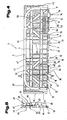
- a container 1 sometimes referred to as tray, shown, which is suitable for the transport of food, especially fresh produce such as fruits, vegetables, but also for packaged foods such as milk bottles, milk packets or the like.
- the container 1 consists of several, in particular four or more plates 2 to 6, wherein in the illustrated container with a rectangular base surface, unlike those with a triangular base five plates 2 to 6 are arranged.
- the plate 6 forms a bottom and the plates 2 and 4 form end walls and the plates 3 and 5 longitudinal side walls. This name was chosen only because the bottom, namely the plate 6, forms a rectangular area. Of course, if the bottom is square, all four plates 2 to 5 forming the side walls have approximately the same length.
- the individual plates 2 to 6 can be configured as desired and be formed for example by a truss structure, a spar construction or a plate with one or both sides projecting reinforcing ribs.
- each of the plates 2 to 6 is provided on surfaces facing each other in a planar manner with a small number of openings 7, e.g. for ventilation of an interior 8, is provided.
- cutouts 9, which are designed and usable as handles, may be arranged in the plates 2 to 5.
- the embodiment in which the mutually facing surfaces of the plates 2 to 6 are formed smoothly and without ribbing, has the advantage that damage to the food to be transported by protruding parts can be prevented and on the other hand, a good cleaning after use is possible.
- the plates are 2 to 5 with the the bottom forming plate 6 is connected via pivoting devices 10.
- pivoting devices 10 consist of a pivot pin 11, which is arranged on a connecting web 12 distanced from a facing this end edge 13 of the plates 2 to 5 fixed.
- This pivot pin 12 is pivotally mounted in a bearing housing 14, if necessary removable.
- This bearing housing 14 is formed by over an inner surface 15 in the peripheral edge region projecting edge strips 16, in which are arranged for receiving the pivot pin 11 over a partial length of the respective plate at a distance from each other, grooves 17 are provided.
- the grooves 17 are open in the direction of the opposite side wall or end wall, so that the pivot pin 11 at approximately parallel to the ground adjusted position of the side walls forming Plates 2 to 5, these can be inserted into the recessed grooves 17 and removed therefrom. This insertion and removal can be done by elastic deformation of locking pins or locking surfaces, but this is not mandatory.
- each plate 2 to 5 to the bottom plate 6 By a relative displacement of each plate 2 to 5 to the bottom plate 6 in each case in the longitudinal direction of the associated end edge 13 of the plate 6 is one of two projecting beyond the connecting web 12 end portions 18 of the pivot pin 11 in a holding lug 19 forming part of the groove 17th inserted.
- This retaining lug 19 is formed by a part of the groove 17 is covered by a cladding element 20.
- end portion 18 of the pivot pin 11 of the connecting web 12 comes into a recess 21 in a groove 17 forming the side cheek 22 and optionally at least a portion of a base plate 23 arranged recess 21 which extends parallel to the longitudinal direction of the pivot pin 11 Length that corresponds to at least one measured in the same direction width of the connecting web 12.
- This recess 21 extends over a pivoting range of at least 90 °, relative to the longitudinal central axis 24 of the pivot pin 11.
- An open length 25 of the groove 17 facing the central region of the plate 6 forming the bottom is equal to or slightly larger than a length 26 of the pivot pin 11.
- the plates 2 to 5 Due to the design of the recesses 21 in conjunction with the pivot pin 11 and the connecting webs 12, it is now possible, the plates 2 to 5, so the end faces forming plates 2 and 4 and those longitudinal sides forming plates 3 and 5 from a flat on the ground resting - inwardly folded transport position - in a 180 ° outwards, the bottom forming plate 6 superior, approximately parallel to this - transport or cleaning position - to pivot outwards, so that they outside the peripheral front side edge of the bottom plate forming 6 come to rest.
- the position of use of the individual plates 2 to 5 relative to the bottom forming plate 6 is located between the parallel to the plate 6 extending outwardly or inwardly pivoted position in which they are aligned perpendicular to the plate 6 and with this an angle of 90 Enclose between itself and the plate 6.
- the groove 17 has an approximately U- or C-shaped cross-section, wherein a symmetrically extending between the legs vertical axis at an angle of 5 ° to 25 °, preferably 8 ° to 20 °, to the surface of the soil is inclined so, that it rises to the central region of the bottom forming plate 6.
- a relative displacement between the plate 6 and the plates 2 to 5 and the plates 3 and 5 is possible, so that they are guided perpendicular to their inner surface 28 projecting stop strips 29, in the pivoting region of which the front side walls forming plates 2, 4th facing end edges 30, 31 overlap and therefore prevent a relative displacement between the plates 3, 5 and 6.
- stop strips 29 in their folded onto the plate 6 position, the parallel to the end edges 30 extending end edges 32, 33 of the transverse side walls forming plates 2, 4 overlap.
- stop bars 29 instead of the arrangement on the longitudinal side walls forming plates 3, 5 on the transverse side walls forming plates 2, 4, so that these gegentician these longitudinal side walls 3, 5 or parallel to these front side edges overlap the bottom forming plate 6.
- edge strips 16 which form the bearing housing 14 for the pivot pin 11, an approximately U-shaped receiving channel is formed together with the bottom forming plate 6 and are by these edge strips 16, the transverse side walls forming plates 2, 4 in the angular range in which the grooves 17 are opened to the center of the bottom plate 6, guided laterally, so that the end portions 18 of the pivot pin 11, which are guided in the retaining lugs 19, can not be pushed out of the retaining lugs 19 in this region of the pivoting movement.
- a length 35 is equal to or slightly smaller than an inner width 36 between the mutually facing side surfaces of the bearing housing 14 for receiving the pivot pin 11 of the longitudinal side walls forming plates 3 and 5. Furthermore, also an inner width 37 between the stop bars 29 each of the longitudinal side walls forming plates 3 and 5 equal to or slightly larger than a maximum distance 38 between mutually averted end edges 39 of the bearing housing 14 for receiving the pivot pin 11 of the transverse side walls forming plates 2 and 4.
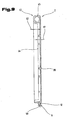
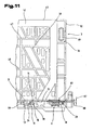
- this plate 3 on a reinforcing bracket 42, which is formed by a hollow body.
- This reinforcing bar 42 extends approximately along narrow end faces 43, 44 from the end edge 13 in the direction of a longitudinal end side edge 45.
- the vertically extending portions of the reinforcing bracket 42 are connected via arch members with the horizontal portions of the reinforcing bracket 42.
- the reinforcing bar 42 is offset or set back at least over the portion of a height 46 of the plate 3 at least by the thickness of the corner post in the direction of the central longitudinal area.
- the reinforcing bar 42 consists of a plastic hollow profile.
- This plastic hollow profile can preferably be produced by an injection process and subsequent blowing out of the soul of the injection-molded part, as long as the plastic material in the central region is still in the liquid or plastic state, in one operation with the other parts of the plate 3 and 5 respectively.
- Zentriencies foundedungen 51 are arranged, which can cooperate with corresponding centering projections 52 in the bottom forming plate 6 of the overlying container 1. Since in this area also a relatively high introduction of force begins, the two successive diagonal supports 50 end approximately in this area to the massively occurring forces evenly over the longitudinal side wall 3, 5 or the individual side members 47, 48 and vertical supports 49 between the Reinforcement bracket 42 and the pivoting devices 10, especially against bulging, stiffen.
- pivot pins 11 are arranged distributed over the length of the end edge 13 of the plate 3, 5.
- pivoting limiter 53rd it has proved to be advantageous to arrange the pivoting devices 10 in pairs next to each other and between each pair of pivoting devices 10 is then a pivoting limiter 53rd
- This pivoting limiter 53 is to achieve the positioning of the longitudinal side walls forming plates 3, 5, but possibly also the plates 2, 4, a retention of the plates 2 to 5 in their erected position.
- a footprint 54 of this swivel limiter 53 also serves as overload protection for the pivoting devices 10. Namely, the pivoting devices 10 applied with a non-preplanned higher load, so the footprints 54 can be supported on the associated opposite support surfaces 55 on the bottom forming a plate 6 and Thus, reduce the maximum on the pivoting device 10 and the pivot pin 11 acting load.
- a high surface pressure is achieved at least between the end portions 18 of the pivot pin 11 and the bearing housing 14 and the groove 17, which also forms strong against the side walls forming by this on the swiveling devices 10 transmitted basic load on the plates 2 to 5 vertical loads Plates 3 and 5 directed blows a leakage of the exposed end portions 18 of the pivot pin 11 from the grooves 17 associated therewith prevented.
- Each of the plates 2 to 5 has an approximately equal thickness 34.
- an axis 59 of the pivot pin 11 extending in the plane of the inner surface 28 is preferably arranged at a greater distance from the inner surface 28 than half the thickness 34 of the individual plates 2 to 5.
- the thickness 34 of the individual plates 2 to 5 results from a height 62 around which an outer peripheral, the plates 2 to 5 limiting, edge strip 63 protrudes beyond an inner surface 28 opposite outer surface 64 of the plates 2 to 5, and a thickness 65 of the respective plate 2 to 5.
- For stiffening of the plates 2 to 6 are within the, bordering the plates, edge strips 63 already mentioned above longitudinal beams 47, 48, vertical beams 49 and diagonal braces 50, as best seen in the views of Fig. 4 and 6 visible, arranged.
- edge strips 63 protrude beyond the outer surface 64 of the plates 2 to 6, protrude at the plates 3 and 5, which form the longitudinal side walls, in the region of the narrow end faces 43, 44 stop strips 29 by the height 40 before, as already with reference to Fig. 1 has been described.
- edge strips 29 are on a central region of the plate 3, 5 side facing support or centering elements 66, 67, 68 are arranged, which will be described later with reference to the transverse side walls forming plates 2 and 4, with correspondingly opposite support or Centering elements in the edge regions of the narrow end sides of the plates 2 to 4 cooperate.
- a connecting element 69 of a connecting device 70 for releasably connecting the plates 2, 4 is arranged with the plates 3, 5 in their upright, approximately perpendicular to the plate 6 extending layer.
- connection device 70 The details of this connection device 70 will be explained in more detail with reference to detailed representations in the sequence.
- the edge strip 63 is formed in the region of the pivot pin 11 opposite longitudinal end edge 45 as a hollow profile.
- the cavity in this region of the edge strip 63 can be carried out in the course of the manufacturing process by blowing, during the cooling process still plastified or liquid, plastic from the shell already in solidification, as in itself from the prior art in various embodiments is known.
- air-mold the description of the DE 39 40 186 A1 made to the content of this application.
- a plurality of pivot pins 11 are arranged, which are each provided via their own connecting webs 12 at a distance from the end edge 13.
- the, about the connecting webs 12 at a distance from the end edge 13 th supported pivot pin 11 are arranged in pairs, wherein the longitudinal center of the plates 3 and 5 nearest pairs of pivot pins 71 and 72 have a smaller distance 73 between the individual pivot pin 11, as in the area Schmalstirnuza 43, 44 arranged pivot pin pairs 74, 75 in which the pivot pins 11 are arranged at a distance 76 from each other.
- each pivot limiter 53 are arranged between these pairs of pivot pins 71, 72, and 74, 75.
- a length 77 of the Schwenkbeskyr 53 in the direction of the narrow end faces 43, 44 between the pairs of pivot pins 71, 72 is less than between the pairs of pivot pins 71 and 74 and 72 and 75.
- the greater length of the Schwenkbeskyr 53 in the narrow end faces 43, 44 prevents falling back of the plates 2 to 5 better, since the plates in the corners, due to any eccentrically protruding parts by weight, rather have the tendency to fold inward, not last by the arrangement of the projecting stop strips 29 with the support or centering elements 66 to 68th
- the difference between the length 77 and the length 80 usually corresponds to one, over the connecting web 12 projecting, journal length 81 of the end portion 18, so that after insertion of the pivot pin 18 in the groove 17, the entire journal length 81 by relative displacement of the plates 2 to 5 relative to the plate 6 introduced into the holding lug 19 in the bearing housing 14, and thus a correspondingly large guide and support surface can be achieved.
- the length 80 by a greater extent than the journal length 81 may be longer than the length 77 of the pivot limiter 53rd
- a height 82 of the pivot limiter 53 is expediently the same size as a width 83 - as in the Fig. 1
- the connecting web 12 is dimensioned such that a measure 87 between the end edge 13 and a facing this closest surface portion of the end portion 18 of the pivot pin 11 is slightly larger than a distance 88 between the end portion 18 and the end edge 13 facing surface of the cladding element 20, wherein this measure 87 corresponds to a voltage applied to the cladding element 20 end portion 18 of a thickness 89 of the cladding element 20.
- these dimensions may also be different, so that depending on the forces acting on the plates 2 to 5, acting on the bottom forming plate 6 forces either either first additionally on the front edge 13 or the pivot limiter 53, and then on the respective other part are introduced into the bottom forming plate 6.
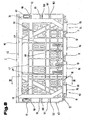
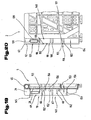
- FIGS. 8 to 11 is then one of the plates 2, 4 which form the transverse side walls of the container 1, shown in detail and described, wherein for similar parts as in the plates 3, 5, the same reference numerals are used.
- this plate 2 in turn has a reinforcing bar 42, which is formed by a hollow body and was prepared by a known from the prior art method, as already in the detailed description of the Fig. 4 to 7 was explained in detail.
- pivoting devices 10 are arranged, which are formed by connecting webs 12 of the end edge 13 distant pivot pin 11.
- These pivot pins 11 have the two end portions 18, 60, which project in the direction of the longitudinal extent of the plate 2 on both sides via the connecting web 12.
- a pivot pin pair 93, 94 is assigned over a width 90 in each case in the direction of narrow end faces 91, 92.
- Another pivot pin 11 is associated with the central region of the plate 2 in the region of the end edge 13.
- a distance 95 between the pivot pin 11 of the two pairs of pivot pins 93, 94 is less than a distance 96 between that in the central region of the plate second associated pivot pin 11 and the pivot pin 11 adjacent pivot pin 11 of the two pivot pin pairs 93, 94th
- the aforementioned reinforcing bracket 42 extends along the longitudinal end edge edge 45 of the plate 2, then extends on both sides of the plate 2 parallel to the narrow end faces 91, 92 and jumps on both sides of the plate 2 obliquely in the direction of the end edge 13 extending toward a center of the plate 2 and ends in the region of the edge strip 63 of the plate 2, wherein this reinforcing bar 42 or the end edge 13 facing end portions of the reinforcing bar 42 in the region of the distance 95 between the pivot pin 11 of the pivot pin pairs 93, 94 is arranged.
- the plate 2 similar to the plate 3 longitudinal members 47, 48, diagonal braces 50 and vertical support 49, whereby a better load transfer over the plate 2 is achieved in the plate 6 formed as a bottom.
- a very good spatial stiffening but above all a high vertical load through the plates 2, 4, are added.
- centering recesses 51 are again arranged, which can cooperate with corresponding centering projections in the plate 6 of the overlying container 1 forming the base. Since a relatively high introduction of force by the overlying container 1 occurs in this area, the two aligned diagonal supports 50 end approximately in the region of these ZentrierausEnglishept 51, the massively occurring forces evenly over the transverse side wall or on the additionally arranged longitudinal members 47, 48 and vertical supports 49 can be derived evenly in the trained as a bottom plate 6.
- the power dissipation in the plate 6 formed as a bottom is further improved in that the end edge 13 facing end portions of the reinforcing bracket 42 in the region of distances 95 between the pivot pin 11 of the pivot pin pairs 93, 94 end and so the derived via the reinforcing bar 42 force evenly can distribute to the two pivot pins 11 of the two pivot pin pairs 93, 94 and so overloading of a single pivot pin 11 and its end portions 18, 60 can be avoided.
- the plate 2 and the plates 2, 4 now have in the region of their narrow end faces 91, 92 extending from the skirt 63 in the direction of the reinforcing bracket 42 and a thickness 97, the plates 2, 4 in the region between the reinforcing bracket 42 and Have pivoting device 10 - as this in the Fig. 9 is shown - projecting support or centering 98 to 102 on.
- These support or centering elements 98 to 102 act to improve the power dissipation and centering in the connecting region of the plates 2, 4 with the plates 3, 5 with the support or centering elements 66 to 68 of the stop strips 29 of the plates 3, 5 together, such as this will be detailed in the following description.
- the plates 2, 4 in the region of the narrow end faces 91, 92 a reduced thickness 103 compared to the thickness 103 on.
- the thickness 103 is compared to the thickness 34 by a thickness 104 of the stop bars 29 of the plates 3, 5 is less to intervene in an engagement of the stop strips 29 of the plates 3, 5 in the edge regions of the plates 2, 4 in one of the plates 2 to 5 locking position in the region of the narrow end faces 91, 92 of the plates 2, 4, the thickness 34 is not exceeded.
- connection receptacle of the connecting device 70 is arranged to receive the connecting element 69, wherein the more accurate design of this connecting device 70 in the following Description will be discussed in more detail.
- Each of the plates 2 to 5 has approximately the same thickness 34.
- an axis 59 of the pivot pin 11 extending in the plane of the inner surface 28 is arranged at a smaller distance from the inner surface 28 than half the thickness 34 of the individual plates 2 to 5.
- the thickness 34 of the individual plates 2 to 5 results from the height 62, around which the outer circumferential, the plates 2 to 5 limiting, edge strip 63 protrudes beyond an inner surface 28 opposite outer surface 64 of the plates 2 to 5, and the thickness 97 of the respective plate 2, 4.
- the stiffening of Plates 2 to 5 are within the, the plates 2 to 5 bounding edge strips 63, the already mentioned side members 47, 48, vertical beams 49 and diagonal braces 50, as best seen in the views of Fig. 4 . 6 . 8th . 10 and 11 visible, arranged. How further the Fig. 9 can be seen, the edge strip 63 is formed in the region of the opposite of the pivot pin 11 longitudinal end edge 45 as a hollow profile.
- the connecting web 12 is dimensioned such that a measure 87 between the end edge 13 and a facing this closest surface portion of the end portion 18 of the pivot pin 11 is slightly larger than a distance 88 between the end portion 18 and the end edge 13 facing surface of the Cladding element 20, wherein the distance 88 corresponds to a voltage applied to the cladding element 20 end portion 18 of a thickness 89 of the cladding element 20.
- these dimensions may also be different, so that depending on the forces acting on the plates 2 to 5, acting on the bottom forming plate 6 forces either either first additionally on the front edge 13 or the pivot limiter 53, and then on the respective other part are introduced into the bottom forming plate 6.
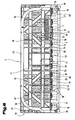
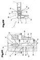
- the bottom forming plate 6 is shown in a front or side view. It can be seen that the plate 6 formed as a bottom for the plates 2, 4 and 3, 5 edge strips 16 having different heights.
- a total thickness 105 of the bottom and the edge strip 16 with the bearing housings 14 in the frontal region of the plate 6 and in the area for receiving the plates 2, 4 corresponds to a sum of a thickness 106 of the plate 6 plus a thickness 107 of the pivot pin 11 and a thickness 108 of the cladding element 20, wherein preferably the thickness 107 of the pivot pin 11 of the pivoting device 10 is equal to a diameter 109 of the pivot pin 11 receiving groove 17.
- the pivot pin 11 is disposed on the plates 2 to 5 in the plane of the inner surface 28 extending axis 59 of the pivot pin 11 at a smaller distance from the inner surface 28 of the plates 2 to 5 than half the thickness 34 of the individual plates 2 to 5.
- a total thickness 110 of the edge strips 16 with the bearing housings 14 for the plates 3, 5 is preferably higher by the thickness 34 of the plates 2, 4 than a total thickness 105 of the edge strips 16 with the bearing housings 14 in the region of the plates 2, 4.
- the plate 6 formed as a base has projecting webs 112 on a lower side 111 which is intended to serve for depositing the containers 1 on a substrate.
- an outer dimension 113 of the webs 112 extends in the side view of the plate 6 and an outer dimension 114 of the webs 112 in the end view of the plate 6, wherein the outer dimension 113 in approximately an inner width 115 between plates 2, 4 in their erected locked position - this in the Fig. 2 is illustrated and corresponds to an outer dimension 114 approximately at an inner width 116 between the plates 3, 5 in their vertical erected and locked position.
- the edge strip 16 for the plates 3, 5 by a measure 118 against the end edges 39 of the edge strips 16 for the plates 2, 4 before.
- This measure 118 corresponds approximately to the thickness 104 of the stop strips 29 of the plates 3, 5, whereby a flat end face of the folded into the transport position container 1 is achieved.
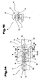
- FIGS. 14 to 18 is now the formation of a pivoting device 10 according to the invention with inserted into the groove 17 pivot pin 11, which has the end portions 18, 60 shown.
- the bearing housing 14 is designed here such that the pivot pin 11 is shown with its two end portions 18, 60 and the pivot pin 11, each with a plate 2 to 5 connecting connecting web 12.
- the end portion 18 of the pivot pin 11 has the front side, the conically extending guide surface 78, said guide surface 78 adjacent the retaining lug 19 of the groove 17 is arranged, which serves to receive the end portion 18 of the pivot pin 11.
- the plates 2 to 5 have in the region of the bottom plate 6 facing end edges 13 of the plates 2 to 5 pivoting devices 10 and are adjustably connected in their erected position and at least one parallel to a front edge 13 of a plate 2 to 5 extending pivot pin 11 is supported by the this facing end edge 13 of the plate 2 to 5 spaced over a connecting web 12 and in the groove 17 of another plate 6 is used.
- the groove 17 has a groove base 120, which is concave, wherein the groove 17 has two end portions 121, 122 and the end portion 122 is closed by a diameter 123 of the groove 17 through the retaining lug 19 and the cladding element 20 and a receiving chamber 124 forms for the end portion 18 of the pivot pin 11.
- a diameter 123 of the groove 17 is preferably equal to a diameter 107 of the pivot pin 11, whereby a play-free fit of the pivot pin 11 in the groove 17 and the closed by the cladding element 20 retaining lug 19 is ensured.
- the groove 17 is now arranged at least in some areas in a bearing housing 14, in a projecting over the plate 6 skirt 16 and has the open length 25, which corresponds at least to the length 26 of the pivot pin 11.
- a distance 125 between the holding lug 19 and the stop 27 is at least equal to a length 126 of the connecting web 12 measured in the direction of the longitudinal central axis 24 but not greater than the length 126 of the connecting web 12 plus the journal length 81 of the end region 18 of the latter projecting in the same direction Pivot pin 11 is.
- the pivotal connection between the groove 17 and the pivot pin 11 and thus between two plates 2 to 6 is now carried out as follows.
- the entire pivot pin 11 has a length 26 which is equal to or slightly smaller than an open length 25 of the groove 17 is formed, and so the pivot pin 11 can be inserted into the groove 17. This takes place in an angular position of the connecting web 12, wherein the position for assembling the pivoting device 10 should not correspond to the position of use of the container 1.
- a movement of the pivot pin 11 transversely to the longitudinal extension of the groove 17 is prevented by a diameter 123 of the groove 17 is equal to a diameter 107 of the pivot pin 11 and so the pivot pin 11 and the groove 17 have the same longitudinal central axis 24.
- the pivot pin 11 is inserted over the open length 25 of the groove 17 in the groove 17, the pivot pin 11 are guided in the grooves 17 such that a relative movement of the pivot pin 11 in the grooves 17 along the longitudinal central axis 24 in the direction of the holding projection 19 allows becomes.
- the pivot pin 11 is displaced in the direction of the end portion 122 of the groove 17, the end portion 18 of the pivot pin 11 penetrates into the receiving chamber 124 of the retaining projection 19 circumferentially closed by the cladding element 20, this process by the arrangement of the guide surface 78 on the end portion 18 of the pivot pin 11 can be substantially facilitated.
- the end portion 18 of the spigot 11 comes now to an inner end edge 128 of the receiving chamber 124 to the plant, but also a distance between them may be possible since the holding lug 19 facing end side 129 of the connecting web 12 on a connecting web 12 facing end surface 130th the holding approach 19 comes to rest and is guided by this, as the representation of Fig. 18 can be seen.
- an arc length 131 of the recess 21 is crucial to the degree of pivoting of the connecting web 12 and so the pivoting range of the pivot pin 11 and the connecting web 12 having plate 2 to 5 is limited by this recess. So it is possible in this advantageous embodiment, by other shaping, the arc length 131 of the recess 21 to reduce or increase, whereby a reduction or increase in the pivoting range of a plate 2 to 5 can be tuned.
- an opening width 133 of the groove 17 slightly smaller form the diameter 107 of the pivot pin 11, whereby the pivot pin 11 snaps into the groove 17 and an independent exit of the pivot pin 11, can be secured on the groove 17 avoided.
- FIG. 17 Now another variant for the groove 17 for receiving the pivot pin 11 is shown.
- the training largely corresponds to the presentation of the Fig. 16 , wherein in this case the cladding element 20 opposite a recess 134 is arranged, which is adapted to the enveloping circle of the pivot pin 11 and so the pivot pin 11 over its entire surface in this recess 134 rests.
- a height 135 of the groove 17 and the receiving chamber 124 is increased in the region of the longitudinal central axis 24.
- the longitudinal central axis 24 is offset from a means of the opening width 133 and so for removing the pivot pin 11 from the groove 17 by an amount 136, which corresponds to the depth of the recess 134, must be raised.
- the illustrated position of the pivot pin 11 or the connecting web 12 reflects the position of use of the pivoting device 10, i. the position at vertical position of the plates 2 to 5 to the plate 6 erected use position, again. In this position, the largest force is exerted on the pivoting devices 10 and the pivot pin 11 in stacked containers 1, whereby between the groove base 120 and this groove base 120 associated outer surface of the pivot pin 11 builds up a high surface pressure. This surface pressure counteracts a leakage of the pivot pin 11 from the groove 17, as it is due to adverse circumstances, such. by blows on the plates 2 to 5 from the outside, etc., could be caused.
- connection receptacle 137 which corresponds to the connecting element 69 has.
- This embodiment is not limited to the variant described here, but may be arranged in all corner regions of the container 1.
- the stop bar 29 of the plate 5 has, as already described above, on its side facing the longitudinal center of the plate 5, the support or centering elements 66 to 68. Between the support or centering element 66 and the longitudinal end side edge 45 of the plate 5, the connecting element 69 is now arranged. In contrast, the edge region of the plate 2, which forms a covering region 138 with the plate 5, has the connection receptacle 137 associated with it in a congruent arrangement with elastically deformable retention elements 139.
- the connecting element 69 is formed by a mushroom-like extension 140, with respect to which the connection receptacle 137 or the retaining elements 139 has projections 141 for engaging behind the mushroom-like extension 140.
- the connecting element 69 can form any shape or any angular position with respect to the vertical extent of the stop bar 29 and the connection receptacle 137 is arranged in congruent training in the edge region of the plate 2.
- a plurality of the height extension of the stop bar 29th distributed connecting elements 69 and connecting devices 70 are arranged so as to improve the connection of the two plates 2, 5 in its corner region.
- connection receptacle 137 To connect the connecting element 69 with the connection receptacle 137, the plate 5 or the plates 3, 5 is initially moved into a position extending approximately vertically to the plate 6, and then the plates 2, 4 are pivoted up into their position of use. If the connecting elements 69 now meet the connection receptacles 137, they engage with a conical guide surface 142 in a conical receptacle 143 of the connection receptacle 137.
- the conical guide surface 142 of the extension 140 now engages in the conically tapering receptacle 143 of the connection receptacle 137 and the retaining elements 139 opposite to the extension 140 are expanded by a force introduction via the projection 140, whereby an opening width 144 of the connection receptacle 137 is increased ,
- the advantage here is when a frontal width 145 of the extension 140 is lower one of this end face of the extension 140 facing opening width 146 of the retaining elements 139.
- This advantageous embodiment it is possible, before snapping the extension 140 in the connection receptacle 137 this in the correct position to center and so facilitate a connection between the plates 2, 4 with the plates 3, 5.
- this arrangement has validity for all possible forms of the connecting elements 69 or connecting receptacles 37, wherein the connecting elements 69 or connecting receptacles 137 can be circular, square or polygonal.
- the resilient configuration of the retaining elements 139 is achieved by the elasticity of the plastic material and by the arrangement of any number of recesses 147 along the retaining elements 139.
- the retaining elements 139 are extended opposite to the extension 140, wherein they slide along the guide surface 142 of the extension 140 and engage the extension 140 when the connection of the side walls 2, 5 and thus an automatic release the plate 2 is prevented by the plate 5.
- the elastically deformable design of the retaining elements 139 of the connecting receptacle 137 ensures that the connecting device 70 can be released again if necessary, wherein the force application in the opposite direction, as described above, must be applied.
- a conical guide surface can again be arranged on the retaining elements 139 on the side opposite the conical receptacle 143.
- the support or centering elements 66 to 68 and the support or centering 98 to 102 are on the stop bar 29 of the plate 5 and in the edge region of the plate 2, the support or centering elements 66 to 68 and the support or centering 98 to 102 arranged.
- the support or centering elements 66 to 68 and 98 to 102 in their assigned areas of the plates 2, 5 and 3, 4 abut each other in a plurality of mutually different spatial directions.
- the support or centering elements 66 to 68 and 98 to 102 may have any possible shape of the shape, but preferably be S-shaped or L-shaped, however, straight webs may also be used as support or centering elements 66 to 68 and 98 to 102.
- the support or centering elements 98, 99 form in the edge regions of the plates 2, 4 a support receptacle 148 for the in the locked state of the two plates 2, 5 between the support or centering elements 98, 99 engaging support or centering elements 66, 67 which are arranged on the stop bar 29 of the plate 5, from.
- a support receptacle 149 for the support or centering 99, 100 of the plate 2, 4.
- a further support receptacle 150 for a further support or centering element 151 on the stop bar 29 of the plates 3, 5.
- the support or centering elements 66 to 68 have transition regions 152 which extend parallel to a height extent of the plate 5 and are distanced from the inner surface 28 of the plate 5 by a distance 153.
- the distance 153 is equal to a thickness 154 of the skirt 63 of the plates 2, 4, whereby the transition areas 152 of the plate 3, 5 assigned Areas of the edge strip 63 of the plates 2, 4 form-fitting between the inner surface 28 and the transition regions 152 on or eino.
- FIGS. 23 and 24 now the overlapping areas of the support or centering elements 66 to 68 of the plate 5 with the support or centering elements 98 to 100 of the plate 2 are shown in detail.
- outer sides 157 of the support or centering elements 98 to 100 fit positively against outer sides 158 of the support or centering elements 66 to 68 of the stop bar 29.
- An advantage of such an embodiment is in this case when a height 159 of the support or centering elements 98 to 100 is equal to a height 160 of the support or centering elements 66 to 68, whereby the best possible load transfer on the outer sides 157, 158 is made possible. Furthermore, a desirable stability of the container 1 is substantially increased thereby.
- the outer sides 157, 158 in such a form as inclined surfaces, that they engage in the connected state of the plate 2 with the plate 5 in a corresponding manner.
- the support or centering 98 to 100 of the plate 2 tapering in the direction of the stop bar 29 of the plate 5 and, in contrast, the support or centering elements 66 to 68 of the stop bar 29 of the plate 5 also in the direction of the plate 2 tapered.
- the support or centering elements 66 to 68 are L-shaped and connect the transition regions 152 and the sub-regions 156 at right angles to the support or centering elements 66 to 68.
- this spatial form can be a much higher stability of the support or centering elements 66 to 68 reach, as is clear Fig. 19 is apparent.
- the plates 3, 5 in turn have in their upper end region or in the region of the longitudinal end side edge 45, the reinforcing bar 42, wherein the reinforcing bar 42 formed as a hollow profile on the side facing away from the inner surface 28 partially recesses 162 along the longitudinal extent of the reinforcing bar 42, which is along the longitudinal extent of the reinforcing bracket 42 form projections 163. Furthermore, the reinforcing bar 42 has further recesses 164 along its longitudinal extent, wherein a depth of these recesses 164 is greater than a wall thickness 165 of the hollow profile of the reinforcing bar 42.
- 5 are on the inner surface 28 opposite side of the plate 3 from the reinforcing bracket 42 in the direction of a reinforcing bar 166 extending over the longitudinal extension of the plates 3, 5 distributed reinforcing ribs 167 integrally formed on the plate 3 in that the reinforcing ribs 167 taper away from the reinforcing bar 42 in the direction of the inner surface 28 of the plate 3 and run parallel to the inner surface 28 of the plate 3 in an end region facing the reinforcing strip 166.
- the reinforcing strip 166 adjacent in the direction of the reinforcing bar 42 is a breakthrough 168 extending through the plate 3 and extending over the entire longitudinal extent of the plate 3 and limited by the stop strips 29 of the plate 3.
- This opening 168 is straddled by the reinforcing ribs 167 arranged between the reinforcing bar 42 and the reinforcing bar 166, whereby the stability of the plate 3, 5 is not reduced by the opening 168.
- the side walls forming plates 3, 5 overlap each other in their resting position on the bottom forming plate 6 transport position and a thickness 169 of the superimposed plates 3, 5 is not greater than the thickness 34 of a single one of the plates 2 to 5. Furthermore, an outer side surface 170 of the reinforcing bar 42 engages in a counter-running groove in the reinforcing bar 42 of the opposite plate 3, 5 a.
- the groove 17 is arranged at least in partial areas in a projecting over one of the plates 2 to 5 skirt 16 and an open length 25 which corresponds at least to the length 26 of the pivot pin 11 and in the area one of the side cheeks 22 of the groove 17 a pivoting portion of the connecting web 12 about a longitudinal central axis 24 of the groove 17 releasing extending in the radial direction recess 21 is arranged, which is limited in the direction of the longitudinal center axis 24 of the groove 17 by the retaining lug 19 and a stop 27 and a distance 125 between the retaining lug 19 and the stop 27 is at least equal to a parallel to the pivot pin 11 extending length 126 of the connecting web 12 but not greater than the sum of the length 126 of the connecting web 12 and a journal length 81 of the projecting beyond this in the same direction end region 18 of the pivot pin eleventh
- the connecting device 70 is formed by a plate 3, 5 fixedly arranged connecting element 69, which projects in the direction of the further plate 2, 4 and this on the further plate 2, 4, a connection receptacle 137 with elastic deformable retaining elements 139 is associated in a congruent arrangement.
- the support or centering elements 66 to 68, 151 and 98 to 102 are arranged in the plane of a plate 2 to 5 in a plurality of mutually different spatial directions.
Claims (68)
- Conteneur constitué de plusieurs plaques (2 à 6), dont plusieurs des plaques (2 à 4) sont reliées d'une manière ajustable dans la zone de leurs arêtes frontales (13) par des dispositifs de pivotement (10) à la plaque (6) réalisée comme fond, et au moins un pivot (11) s'étendant parallèlement à une arête frontale (13) d'une plaque (2 à 5) est retenu par une baguette de liaison (12) à distance de celle-ci et peut être inséré dans une, de préférence plusieurs rainures (17) d'une autre plaque (6), et des bouts rapportés de retenue (19) sont disposés, et un bout rapporté de retenue (19) pour former un logement de réception (124) pour l'une des deux zones d'extrémité (18, 60; 121, 122) du pivot (11) est formé par un élément de revêtement (20) recouvrant une partie de la rainure (17) dans sa zone d'extrémité (18, 60; 121, 122) sur sa largeur, et la rainure (17) est disposée au moins dans des zones partielles d'une baguette de bord (16) faisant saillie sur l'une des plaques (2 à 5) et présente une longueur ouverte (25) qui correspond au moins à la longueur (26) du pivot (11) et, au voisinage d'une des joues latérales (22) de la rainure (17), un évidement (21) s'étendant dans la direction radiale, libérant une zone de pivotement de la baguette de liaison (12) autour d'un axe médian longitudinal (24) de la rainure (17) est disposé, qui est limité dans la direction de l'axe médian longitudinal (24) de la rainure (17) par le bout rapporté un l'autre retenue (19) et une butée (27), et un écart (125) entre le bout rapporté de retenue (19) et la butée (27) est au moins égal à une longueur (126) de la baguette de liaison (12) s'étendant parallèlement au pivot (11) mais non pas plus grand que la somme de la longueur (126) de la baguette de liaison (12) et d'une longueur de pivot (81) de la zone d'extrémité (18) du pivot (11) faisant saillie sur celle-ci dans la même direction, caractérisé en ce que la rainure (17), dans les baguettes de bord saillantes (16), est réalisée ouverte en direction des plaques opposées (2 à 5) réalisées comme parois latérales par les longueurs ouvertes (25) vers l'intérieur du conteneur.
- Conteneur selon la revendication 1, caractérisé en ce qu'il est disposé entre au moins deux pivots (11) disposés au voisinage d'une arête frontale (13) d'une plaque (2 à 5), un organe de limitation de pivotement (53) actif au moins dans une position redressée de la plaque (2 à 5) qui, à un écart angulaire en avant dans la direction de pivotement pour le redressement de la plaque (2 à 5) fait saillie sur un cercle enveloppant qui s'étend coaxialement à un axe (59) du pivot (11) et présente un rayon qui correspond à une mesure (87) selon laquelle l'axe (59) est espacé de l'arête frontale (13) orientée vers celui-ci de l'autre plaque (2 à 5).
- Conteneur selon la revendication 1 ou 2, caractérisé en ce que celui-ci est notamment réalisé en matériau synthétique et présente un fond et au moins deux plaques (2 à 5) reliées d'une manière ajustable à la plaque (6) réalisée comme fond par des dispositifs de pivotement (10), et en ce que dans une zone de recouvrement (138) entre des côtés frontaux étroits (43, 44; 91, 92) des plaques (2 à 5), un dispositif de liaison (70) pour relier relâchablement les plaques (3, 5; 2, 4) est disposé, qui s'oppose dans une position des plaques (3, 5; 2, 4) s'étendant à peu près perpendiculairement au fond à un relâchement automatique du dispositif de liaison (70), où le dispositif de liaison (70) est formé par un élément de liaison (69) disposé fixement dans une plaque (3, 5), qui fait saillie en direction de l'autre plaque (2, 4), et qu'il est associé à celui-ci sur l'autre plaque (2, 4) un logement de liaison (137) avec des éléments de retenue élastiquement déformables (139) selon un agencement congruent.
- Conteneur selon l'une des revendications 1 à 3, caractérisé en ce que celui-ci est réalisé notamment en matériau synthétique et présente un fond avec au moins deux parois latérales reliées d'une manière ajustable au fond par des dispositifs de pivotement (10), et en ce que sont disposées dans une zone de recouvrement (138) entre une face frontale, une paroi latérale et une face intérieure de l'autre paroi latérale des éléments d'appui respectivement de centrage (66 à 68, 151, 98 à 102) formés par des saillies et des évidements qui, lors d'une position redressée des parois latérales, sont fixés relâchablement en s'engageant les uns dans les autres par concordance des formes, et respectivement plusieurs saillies et évidements sontjuxtaposés en une rangée verticale des bords avoisinants des parois latérales, et en ce que les éléments d'appui et de centrage (66 à 68, 151 et 98 à 102) sont disposés dans le plan d'une plaque (2 à 5) dans plusieurs directions spatiales s'étendant différemment les unes aux autres.
- Conteneur selon la revendication 1, caractérisé en ce qu'une mesure (87) entre l'arête frontale (13) des plaques (2 à 5), orientée vers la plaque (6) réalisée comme fond et une partie de surface la plus proche, orientée vers celle-ci, de la zone d'extrémité (18) du pivot (11) est légèrement plus grande qu'une épaisseur (89) de l'élément de revêtement (20).
- Conteneur selon la revendication 1 ou 5, caractérisé en ce que la distance (88) à une zone d'extrémité (18) s'appliquant à l'élément de revêtement (20) correspond à une épaisseur (89) de l'élément de revêtement (20).
- Conteneur selon l'une ou plusieurs des revendications 1, 5 et 6, caractérisé en ce que la différence entre l'épaisseur (89) et la mesure (87) est aussi grande qu'un écart (58) entre la face d'appui (54) de l'organe de limitation de pivotement (53) et la face d'appui (55) des plaques (2 à 5), respectivement de la plaque (6).
- Conteneur selon l'une ou plusieurs des revendications 1 et 5 à 7, caractérisé en ce qu'une différence entre l'épaisseur (89) et la mesure (87) est plus petite que l'écart (58) entre la face d'application (54) et la face d'appui (55) des plaques (2 à 5), respectivement de la plaque (6).
- Conteneur selon l'une ou plusieurs des revendications 1 et 5 à 8, caractérisé en ce que le pivot (11) est formé par la baguette de liaison (12) et de plus par des zones d'extrémité (18, 60) faisant saillie le long de l'axe médian longitudinal (24).
- Conteneur selon l'une ou plusieurs des revendications 1 et 5 à 9, caractérisé en ce que la zone d'extrémité (18) du pivot (11) présente une face de guidage conique (78) s'étendant au côté frontal.
- Conteneur selon l'une ou plusieurs des revendications 1 et 5 à 10, caractérisé en ce que la rainure (17) présente un fond de rainure concave (120).
- Conteneur selon l'une ou plusieurs des revendications 1 et 5 à 11, caractérisé en ce que la rainure (17) présente deux zones d'extrémité (121, 122), et l'une des zones d'extrémité (121, 122), s'étendant sur un diamètre (123) de la rainure (17), est fermée par le bout rapporté de retenue (19) respectivement l'élément de revêtement (20).
- Conteneur selon l'une ou plusieurs des revendications 1 et 5 à 12, caractérisé en ce que le bout rapporté de retenue (19) forme avec l'élément de revêtement (20) un logement de réception (124) pour la zone d'extrémité (18) du pivot (11).
- Conteneur selon l'une ou plusieurs des revendications 1 et 5 à 13, caractérisé en ce qu'un diamètre (123) de la rainure (17) est réalisé pour être aussi grand, respectivement légèrement plus grand qu'un diamètre (107) du pivot (11).
- Conteneur selon l'une ou plusieurs des revendications 1 et 5 à 14, caractérisé en ce que la rainure (17) est disposée dans des zones partielles de la baguette de bord (16) dans les boîtiers de palier (14).
- Conteneur selon l'une ou plusieurs des revendications 1 et 5 à 15, caractérisé en ce qu'une longueur ouverte (25) de la rainure est réalisée pour être au moins égale à une longueur (26) respectivement légèrement plus grande que la longueur (26) du pivot (11).
- Conteneur selon l'une ou plusieurs des revendications 1 et 5 à 16, caractérisé en ce qu'un écart (125) entre le bout rapporté de retenue (19) et la butée (27) est réalisé pour être au moins aussi grand respectivement plus grand qu'une longueur (126) de la baguette de liaison (12) mesurée dans la direction de l'axe médian longitudinal (24).
- Conteneur selon l'une ou plusieurs des revendications 1 et 5 à 17, caractérisé en ce qu'il est disposé entre une face frontale (130) orientée vers la butée (27) du bout rapporté de retenue (19) et la butée (27) de la paroi latérale (22) de la rainure (17) un évidement (21) s'étendant radialement qui présente une longueur d'arc (131).
- Conteneur selon l'une ou plusieurs des revendications 1 et 5 à 18, caractérisé en ce que l'évidement (121) est réalisé pour libérer une zone de pivotement pour la baguette de liaison (12) dans la dimension de la longueur d'arc (131).
- Conteneur selon l'une ou plusieurs des revendications 1 et 5 à 19, caractérisé en ce qu'une zone d'extrémité de la joue latérale (22) orientée vers l'extrémité ouverte de la rainure (17) présente une face inclinée (132) s'étendant en direction de l'axe médian longitudinal (24).
- Conteneur selon l'une ou plusieurs des revendications 1 et 5 à 20, caractérisé en ce qu'une largeur d'ouverture de la rainure (17) est réalisée dans la même grandeur que le diamètre (107) du pivot (11).
- Conteneur selon l'une ou plusieurs des revendications 1 et 5 à 21, caractérisé en ce que la largeur d'ouverture (133) de la rainure (17) est réalisée pour être légèrement plus petite que le diamètre (107) du pivot (11).
- Conteneur selon l'une ou plusieurs des revendications 1 et 5 à 22, caractérisé en ce que le fond (120) de la rainure présente un évidement (134).qui est adapté au cercle enveloppant du pivot (11).
- Conteneur selon la revendication 2, caractérisé en ce qu'une arête latérale (156) de la face d'application (54) à peu près rectangulaire des plaques (2 à 5) fait saillie sur le cercle enveloppant tangent à celles-ci avec une face enveloppante (57) formée par l'axe médian longitudinal (24) du pivot (11).
- Conteneur selon les revendications 2 ou 24, caractérisé en ce que les faces d'application (54) des organes de limitation de pivotement (53) sont disposées à un léger écart (58) au-dessus des faces d'appui (55) associées à celles-ci de la plaque formant le fond.
- Conteneur selon les revendications 2, 24 et 25, caractérisé en ce que la face d'appui (54) des organes de limitation de pivotement (53), dans le cas d'une position des plaques (2, 5) à angle droit à la plaque (6), est espacée relativement à la face d'appui (55) parallèlement et de celle-ci légèrement en hauteur (46) des plaques (2 à 5).
- Conteneur selon l'une ou plusieurs des revendications 2 et 24 à 26, caractérisé en ce que les pivots (11) maintenus par les baguettes de liaison (12) à distance de l'arête frontale (13) sont disposés par paires.
- Conteneur selon l'une ou plusieurs des revendications 2 et 24 à 27, caractérisé en ce que les paires de pivots (71, 72) les plus proches d'un milieu longitudinal des plaques (3, 5) ont une plus petite distance (73) entre les différents pivots (11) que les paires de pivots (74, 75) disposés au voisinage des côtés frontaux étroits (43, 44), où les pivots (11) sont disposés à une distance (76) l'un de l'autre.
- Conteneur selon l'une ou plusieurs des revendications 2 et 24 à 28, caractérisé en ce que des organes de délimitation de pivotement (53) sont disposés respectivement entre les paires de pivots (71, 72 et 74, 75).
- Conteneur selon l'une ou plusieurs des revendications 2 et 24 à 29, caractérisé en ce qu'une longueur (77) des organes de limitation de pivotement (53) dans la direction des côtés frontaux étroits (43, 44) entre les paires de pivot (71, 72) est plus petite que celle entre les paires de pivots (71, 74 respectivement, 72, 75).
- Conteneur selon l'une ou plusieurs des revendications 2 et 24 à 30, caractérisé en ce que la longueur (77) des organes de limitation de pivotement (53) est plus petite qu'une longueur (80) d'un évidement (79) dans le boîtier de palier (14).
- Conteneur selon l'une ou plusieurs des revendications 2 et 24 à 31, caractérisé en ce que la différence entre la longueur (77) et la longueur (80) correspond à une longueur de pivot (81) de la zone d'extrémité (18) faisant saillie sur la baguette de liaison (12).
- Conteneur selon l'une ou plusieurs des revendications 2 et 24 à 32, caractérisé en ce qu'une hauteur (82) des organes de limitation de pivotement (53) est aussi grande qu'une largeur (83) du boîtier de palier (14).
- Conteneur selon l'une ou plusieurs des revendications 2 et 24 à 33, caractérisé en ce qu'une distance (84) entre l'axe médian longitudinal (24) des pivots (11) et la face d'application (54) de l'organe de limitation de pivotement (53) n'est pas plus grande qu'une distance (85) entre l'axe médian longitudinal (24) de la rainure (17) et une paroi latérale intérieure (86) du boîtier de palier (14) qui est orientée vers la plaque (6), respectivement la zone médiane de la plaque (6).
- Conteneur selon la revendication 3, caractérisé en ce que l'élément de liaison (69) est formé par un prolongement en forme de tête de champignon (140).
- Conteneur selon la revendication 3 ou 35, caractérisé en ce que les éléments de retenue (139) déformables élastiquement présentent des saillies pour passer derrière les prolongements (140) en forme de tête de champignon.
- Conteneur selon l'une ou plusieurs des revendications 3 et 35 et 36, caractérisé en ce que les logements de liaison (137) sont réalisés en forme de cercle ou de carré, respectivement en polygone.
- Conteneur selon l'une ou plusieurs des revendications 3 et 35 à 37, caractérisé en ce que les logements de liaison (137) sont réalisés en forme de trou oblong.
- Conteneur selon l'une ou plusieurs des revendications 3 et 35 à 38, caractérisé en ce que les logements de liaison (137) sont disposés angulairement dans une zone de bord des plaques (2 à 5).
- Conteneur selon l'une ou plusieurs des revendications 3 et 35 à 39, caractérisé en ce qu'une largeur (145) au côté frontal du prolongement (40) est plus petite qu'une largeur d'ouverture (146) des éléments de retenue (139) orientée vers ce côté frontal du prolongement (40).
- Conteneur selon l'une ou plusieurs des revendications 3 et 35 à 40, caractérisé en ce que sont disposés le long des éléments de retenue (139), pour obtenir une réalisation élastique de ceux-ci, un nombre sélectif d'évidements (147).
- Conteneur selon la revendication 4, caractérisé en ce que les éléments d'appui et de centrage (66 à 68, 151, 98 à 102) sont réalisés en forme de S et/ou en forme de L.
- Conteneur selon les revendications 4 ou 42, caractérisé en ce que les plaques (2, 4) présentent au voisinage de leurs côtés frontaux étroits (91, 92) des éléments d'appui ou de centrage (108 à 112) s'étendant de la baguette de bord (63) en direction de l'étrier de renforcement (42) et sur une épaisseur (97) que présentent les plaques (2, 4) dans la zone entre l'étrier de renforcement (42) et le dispositif de pivotement (11).
- Conteneur selon les revendications 4, 42 et 43, caractérisé en ce que les éléments d'appui ou de centrage (66 à 68, 98 à 102) sont disposés dans les zones des plaques (2, 5 ou 3, 4) associées à eux d'une manière contiguë dans plusieurs directions spatiales s'étendant différemment les unes aux autres.
- Conteneur selon l'une ou plusieurs des revendications 4 et 42 à 44, caractérisé en ce que sont ménagés dans la baguette de bord (63) des plaques (2, 4) des moulages (155) qui sont réalisés pour la réception de zones partielles (156) des éléments d'appui ou de centrage (66, 67, 151).
- Conteneur selon l'une ou plusieurs des revendications 4 et 42 à 45, caractérisé en ce qu'une profondeur de ces moulages (155) correspond à une hauteur, mesurée perpendiculairement à la baguette de butée (29), des zones partielles (156) des éléments d'appui ou de centrage (66, 67, 151).
- Conteneur selon l'une ou plusieurs des revendications 4 et 42 à 46, caractérisé en ce que les côtés extérieurs (157) des éléments d'appui ou de centrage (98 à 100) s'appliquent par concordance des formes aux côtés extérieurs (158) des éléments d'appui ou de centrage (66 à 68) de la baguette de butée (29).
- Conteneur selon l'une ou plusieurs des revendications 4 et 42 à 47, caractérisé en ce qu'une hauteur (159) des éléments d'appui ou de centrage (98 à 100) est égale à une hauteur (160) des éléments d'appui ou de centrage (66 à 68).
- Conteneur selon l'une ou plusieurs des revendications 4 et 42 à 48, caractérisé en ce que les côtés extérieurs (157, 158) forment des faces inclinées correspondant l'une avec l'autre.
- Conteneur selon l'une ou plusieurs des revendications 4 et 42 à 49, caractérisé en ce que les éléments d'appui ou de centrage (98 à 102) de la plaque (2) diminuent en direction de la baguette de butée (29) de la plaque (5).
- Conteneur selon l'une ou plusieurs des revendications 4 et 42 à 50, caractérisé en ce que les éléments d'appui ou de centrage (66 à 68, 151) de la baguette de butée (29) de la plaque (5) diminuent en direction de la plaque (2).
- Conteneur selon l'une ou plusieurs des revendications précédentes, caractérisé en ce qu'une longueur (35) des plaques (2,4) formant les parois latérales frontales est aussi grande ou légèrement plus petite qu'une largeur intérieure (36) entre des faces latérales orientées l'une vers l'autre des boîtiers de palier (14) pour la réception des pivots (11) des plaques (3, 5) formant les parois latérales longitudinales.
- Conteneur selon l'une ou plusieurs des revendications précédentes, caractérisé en ce qu'une largeur intérieure (37) entre les baguettes de butée (29) de chacune des plaques (3, 5) formant les parois latérales longitudinales est aussi grande ou légèrement plus grande qu'une distance maximale (38) entre les faces latérales frontales éloignées l'une de l'autre des boîtiers de palier (14).
- Conteneur selon l'une ou plusieurs des revendications précédentes, caractérisé en ce que les plaques (2 à 5) formant les parois latérales présentent des supports longitudinaux en forme de tige (47, 48), des supports verticaux (49) et des éléments d'appui diagonaux (50).
- Conteneur selon l'une ou plusieurs des revendications précédentes, caractérisé en ce que sont disposés au voisinage de l'arête latérale longitudinale (45) des évidements de centrage (51) pour la réception de saillies de centrage correspondantes dans la plaque (6) formant le fond.
- Conteneur selon l'une ou plusieurs des revendications précédentes, caractérisé en ce qu'un axe (59) du pivot (11) s'étendant dans le plan de la face intérieure (28) est disposé à une plus grande distance de la face intérieure (28) que la moitié de l'épaisseur (34) des plaques individuelles (2 à 5).
- Conteneur selon l'une ou plusieurs des revendications précédentes, caractérisé en ce que la baguette de bord (63) forme au voisinage de l'arête latérale frontale longitudinale (45) opposée au pivot (11) l'étrier de renforcement (42) et est réalisée comme profilé creux.
- Conteneur selon l'une ou plusieurs des revendications précédentes, caractérisé en ce qu'une épaisseur totale (105) du fond de la baguette de bord (16) avec les boîtiers de palier (14) dans la zone au côté frontal de la plaque (6) correspond à une somme de l'épaisseur (106) de la plaque (6) plus une épaisseur (107) du pivot (11) et une épaisseur (108) de l'élément de revêtement (20).
- Conteneur selon l'une ou plusieurs des revendications précédentes, caractérisé en ce qu'une épaisseur totale (110) des baguettes de bord (16) avec les boîtiers de palier (14) pour les plaques (3, 5) est de préférence plus élevée de l'épaisseur (34) des plaques (2, 4) qu'une épaisseur totale (105) des baguettes de bord (16) avec les boîtiers de palier (14) au voisinage des plaques (2, 4).
- Conteneur selon l'une ou plusieurs des revendications précédentes, caractérisé en ce que la plaque (6) réalisée comme fond présente des baguettes (112) faisant saillie sur un côté inférieur (111).
- Conteneur selon l'une ou plusieurs des revendications précédentes, caractérisé en ce qu'une dimension (113) des baguettes (112), dans la vue de côté de la plaque (6), et une dimension (114) des baguettes (112) dans la vue frontale de la plaque (6) correspond à peu près à une largeur intérieure (115) entre les plaques (2, 4) dans leur position redressée et une largeur intérieure (116) entre les plaques redressées (3, 5).
- Conteneur selon l'une ou plusieurs des revendications précédentes, caractérisé en ce que la baguette de bord (16) pour les plaques (3, 5) fait saillie selon une mesure (118) par rapport aux arêtes frontales (39) des baguettes de bord (16) pour les plaques (2, 4).
- Conteneur selon l'une ou plusieurs des revendications précédentes, caractérisé en ce que la mesure (118) correspond à peu près à une épaisseur (104) des baguettes de butée (29) des plaques (3, 5).
- Conteneur selon l'une ou plusieurs des revendications précédentes, caractérisé en ce qu'une hauteur (46) des plaques (3, 5) formant les parois latérales est plus grande que la moitié de la largeur de la plaque (6) formant le fond.
- Conteneur selon l'une ou plusieurs des revendications précédentes, caractérisé en ce que les plaques (3, 5) formant les parois latérales, dans leur position de transport s'appliquant sur la plaque (6) formant le fond se chevauchent et qu'une épaisseur (169) des plaques superposées (3, 5) n'est pas plus grande que l'épaisseur (34) d'une seule des plaques (2 à 5).
- Conteneur selon l'une ou plusieurs des revendications précédentes, caractérisé en ce qu'une face latérale extérieure de.l'étrier de renforcement (42) s'engage dans une rainure s'étendant en sens opposé dans l'étrier de renforcement (42) de la plaque opposée (3, 5).
- Conteneur selon l'une ou plusieurs des revendications précédentes, caractérisé en ce que les plaques (3, 5) forment une zone de recouvrement (161).
- Conteneur selon l'une ou plusieurs des revendications précédentes, caractérisé en ce que des nervures de renforcement (167) sont disposées dans la zone de recouvrement (161) des plaques (3, 5).
Priority Applications (1)
| Application Number | Priority Date | Filing Date | Title |
|---|---|---|---|
| AT99972181T ATE268295T1 (de) | 1998-11-18 | 1999-11-05 | Behälter aus mehreren platten |
Applications Claiming Priority (3)
| Application Number | Priority Date | Filing Date | Title |
|---|---|---|---|
| AT192598 | 1998-11-18 | ||
| AT0192598A AT411991B (de) | 1998-11-18 | 1998-11-18 | Behälter aus mehreren platten |
| PCT/AT1999/000267 WO2000029294A2 (fr) | 1998-11-18 | 1999-11-05 | Conteneur constitue de plusieurs plaques |
Publications (3)
| Publication Number | Publication Date |
|---|---|
| EP1131249A1 EP1131249A1 (fr) | 2001-09-12 |
| EP1131249B1 EP1131249B1 (fr) | 2004-06-02 |
| EP1131249B2 true EP1131249B2 (fr) | 2008-12-03 |
Family
ID=3523995
Family Applications (1)
| Application Number | Title | Priority Date | Filing Date |
|---|---|---|---|
| EP99972181A Expired - Lifetime EP1131249B2 (fr) | 1998-11-18 | 1999-11-05 | Conteneur constitue de plusieurs plaques |
Country Status (20)
| Country | Link |
|---|---|
| US (1) | US6708836B2 (fr) |
| EP (1) | EP1131249B2 (fr) |
| JP (1) | JP4094817B2 (fr) |
| KR (1) | KR20010105292A (fr) |
| CN (1) | CN1332689A (fr) |
| AR (1) | AR021265A1 (fr) |
| AT (1) | AT411991B (fr) |
| AU (1) | AU759083B2 (fr) |
| BR (1) | BR9915470A (fr) |
| CA (1) | CA2350835A1 (fr) |
| CZ (1) | CZ295888B6 (fr) |
| DE (1) | DE59909662D1 (fr) |
| ES (1) | ES2222760T5 (fr) |
| HU (1) | HU224807B1 (fr) |
| IL (1) | IL143235A (fr) |
| NO (1) | NO20012287L (fr) |
| PL (1) | PL197551B1 (fr) |
| TR (1) | TR200101411T2 (fr) |
| WO (1) | WO2000029294A2 (fr) |
| ZA (1) | ZA200104866B (fr) |
Families Citing this family (27)
| Publication number | Priority date | Publication date | Assignee | Title |
|---|---|---|---|---|
| AT411991B (de) | 1998-11-18 | 2004-08-26 | Steco Logistic Gmbh | Behälter aus mehreren platten |
| US6409041B1 (en) * | 2000-09-21 | 2002-06-25 | Rehrig Pacific Company | Container |
| NL1017844C2 (nl) * | 2001-04-13 | 2002-10-15 | Fountain Tech Bv | Kunststof container en werkwijze voor gebruik daarvan. |
| AT411589B (de) | 2002-06-13 | 2004-03-25 | Zelko Johannes | Zusammenklappbarer kistenförmiger behälter |
| ES1055985Y (es) * | 2003-10-31 | 2004-06-01 | Sp Berner Plastic Group Sl | Caja plegable. |
| US8777542B2 (en) * | 2004-03-29 | 2014-07-15 | Yousef Daneshvar | Daneshvar carrier means and methods |
| US20060054528A1 (en) * | 2004-08-30 | 2006-03-16 | Sanzana Cecil M | Foldable plastic box, assemblable, having 5 cavities, with or without folding upper covers, to contain agricultural products |
| DE202004018927U1 (de) * | 2004-12-07 | 2005-02-24 | Ifco Systems Gmbh | Transportkasten mit klappbaren Seitenteilen aus Kunststoff |
| US20070084864A1 (en) * | 2005-10-14 | 2007-04-19 | The Parallax Group International, Llc | Collapsible container |
| DE102006031120B3 (de) * | 2006-07-05 | 2008-03-06 | Siemens Ag | Sendungsbehälter |
| DE102009036993B4 (de) * | 2009-08-12 | 2014-11-06 | Georg Utz Holding Ag | Transportbehälter |
| US20110221318A1 (en) * | 2010-03-10 | 2011-09-15 | Protrend Co., Ltd. | Collapsible drawer |
| US9469429B2 (en) * | 2010-09-20 | 2016-10-18 | Ifco Systems Gmbh | Crate |
| US9016492B2 (en) | 2010-09-20 | 2015-04-28 | Ifco Systems Gmbh | Crate |
| MA34537B1 (fr) * | 2010-09-20 | 2013-09-02 | Ifco Systems Gmbh | Caisse dotée d'un élément de renfort continu |
| CN106285812B (zh) * | 2012-04-20 | 2019-09-03 | 伊顿智能动力有限公司 | 具有提高的耐久性的摇臂组件 |
| US20150021320A1 (en) * | 2013-07-17 | 2015-01-22 | Jin Huang | Foldable File Tray |
| US9745100B2 (en) * | 2014-08-27 | 2017-08-29 | Rehrig Pacific Company | Stack and fold dairy shelves |
| US11352168B2 (en) * | 2015-06-22 | 2022-06-07 | U.S. Merchants Financial Group, Inc. | Collapsible crate |
| WO2017086503A1 (fr) * | 2015-11-17 | 2017-05-26 | 인팩글로벌(주) | Boîte pliante |
| CN105836254B (zh) | 2016-05-24 | 2018-12-07 | 上海鸿研物流技术有限公司 | 折叠箱 |
| DE202016106088U1 (de) * | 2016-10-28 | 2017-02-06 | Georg Utz Holding Ag | Klapp-Behälter |
| CN106956845A (zh) * | 2017-04-10 | 2017-07-18 | 上海鸿研物流技术有限公司 | 折叠箱 |
| CN108860921B (zh) * | 2018-08-08 | 2020-11-20 | 上海鸿研物流技术有限公司 | 可折叠容器 |
| CN109835570B (zh) * | 2019-02-27 | 2024-02-27 | 上海鸿研物流技术有限公司 | 可折叠容器 |
| US11731803B2 (en) | 2021-07-02 | 2023-08-22 | The Merchant Of Tennis, Inc. | Collapsible crate with stowable hinged lid |
| US11713159B1 (en) * | 2022-06-28 | 2023-08-01 | Jianxing Zhan | Foldable storage box |
Citations (4)
| Publication number | Priority date | Publication date | Assignee | Title |
|---|---|---|---|---|
| WO1997016353A1 (fr) † | 1995-10-31 | 1997-05-09 | Woodall Plastic Products Limited | Conteneur repliable |
| WO1997026190A2 (fr) † | 1996-01-18 | 1997-07-24 | Gebr. Otto Kg | Contenant pliable |
| DE19601679A1 (de) † | 1996-01-18 | 1997-07-24 | Otto Geb Kg | Klappbehälter |
| WO1997039954A1 (fr) † | 1996-04-22 | 1997-10-30 | Perstorp Ab | Conteneur repliable |
Family Cites Families (28)
| Publication number | Priority date | Publication date | Assignee | Title |
|---|---|---|---|---|
| DE1296563B (de) * | 1967-09-16 | 1969-05-29 | Ver Deutsche Metallwerke Ag | Kunststoffkasten mit umlegbaren Seitenwaenden |
| ZA746647B (en) * | 1974-10-18 | 1976-05-26 | Plastipak Pty Ltd | Collapsible container |
| DE3514896A1 (de) * | 1985-04-25 | 1986-11-06 | William Prym-Werke GmbH & Co KG, 5190 Stolberg | Druckknopfverbindung |
| HU204222B (en) | 1989-07-11 | 1991-12-30 | Ferenc Koenig | Space-limiting structure particularly container of polygon cross section |
| US4960223A (en) * | 1989-07-18 | 1990-10-02 | Chiang Pei Lieh | Box crate container |
| CH684208A5 (fr) * | 1990-06-25 | 1994-07-29 | Gueissaz & Cie Sa Andre | Dispositif d'assemblage de deux plaques planes en matière plastique par clipsage. |
| NO172283C (no) | 1991-02-08 | 1993-06-30 | Norsk Hydro As | Sammenleggbar transportkasse |
| CH682208A5 (en) | 1991-08-07 | 1993-08-13 | Beat Bisig | CD storage stand giving good view of contents - uses perpendicular slits in mantle surface of pipe for receiving respective CD cassettes |
| DE9218977U1 (de) | 1992-01-17 | 1996-08-08 | Schoeller Plast Ag | Behälter aus Kunststoff, insbesondere Gemüsebehälter, mit klappbaren Seitenwänden |
| AT401765B (de) * | 1992-11-18 | 1996-11-25 | Furtner Josef | Behälter mit verschwenkbaren seitenwänden |
| DE4243427C1 (de) | 1992-12-15 | 1994-03-10 | Ethicon Gmbh | System zum Applizieren von Knoten in chirurgischem Nahtmaterial |
| DE4242679A1 (de) * | 1992-12-17 | 1994-06-23 | Otto Geb Kg | Zusammenklappbarer Transportbehälter als Mehrwegverpackung |
| AT400703B (de) | 1993-11-19 | 1996-03-25 | Floegl Ingomar | Transport- und lagerbehälter |
| DE4416925C1 (de) | 1994-05-13 | 1995-06-01 | Hella Kg Hueck & Co | Vorrichtung zur Halterung einer Lampe an einem Reflektor eines Fahrzeug-Scheinwerfers |
| EP0784570B1 (fr) * | 1994-10-07 | 1998-08-12 | Schoeller International Engineering S.A. | Recipient plastique pliable |
| AT665U1 (de) * | 1995-04-20 | 1996-03-25 | Josef Haidlmair Maschinen Werk | Transport- und/oder lagerbehälter aus kunststoff |
| CA2153141C (fr) * | 1995-06-30 | 1998-10-06 | Roch Nolet | Recipient en cinq pieces avec parois laterales pliantes |
| GB2303616B (en) * | 1995-07-26 | 1999-09-15 | Mckechnie Uk Ltd | Collapsible container |
| ES2128138T3 (es) | 1996-01-18 | 1999-05-01 | Perstorp Plastic Syst Ab | Contenedor plegable. |
| AU727525B2 (en) * | 1996-04-30 | 2000-12-14 | Steiner Technology Gmbh | Hinge arrangement between two wall parts that are pivotable relative to one another, in particular of a crate-like transport container |
| US5722550A (en) * | 1996-06-06 | 1998-03-03 | Buckhorn Material Handling Group, Inc. | Container having reusable base and disposable over sleeve |
| CA2228541C (fr) * | 1997-02-07 | 2006-04-18 | Hans Umiker | Contenant repliable a parois amovibles verrouillables |
| DE29710794U1 (de) * | 1997-06-20 | 1997-11-13 | Innovations Technologie Und De | Behälter für Backwaren |
| US6015056A (en) * | 1997-12-19 | 2000-01-18 | Rehrig Pacific Company | Collapsible container |
| US6286701B1 (en) * | 1998-02-06 | 2001-09-11 | Schoeller Plast Sa | Container, in particular for transporting fruits and vegetables |
| DE69926290T2 (de) | 1998-03-18 | 2006-04-13 | Nippon Telegraph And Telephone Corp. | Tragbares Kommunikationsgerät mit Anordnung zum Knochenleitungshören |
| AT411991B (de) | 1998-11-18 | 2004-08-26 | Steco Logistic Gmbh | Behälter aus mehreren platten |
| US6891496B2 (en) | 2002-05-03 | 2005-05-10 | Atheros Communications, Inc. | Method and apparatus for physical layer radar pulse detection and estimation |
-
1998
- 1998-11-18 AT AT0192598A patent/AT411991B/de not_active IP Right Cessation
-
1999
- 1999-11-05 TR TR200101411T patent/TR200101411T2/xx unknown
- 1999-11-05 JP JP2000582299A patent/JP4094817B2/ja not_active Expired - Lifetime
- 1999-11-05 ES ES99972181T patent/ES2222760T5/es not_active Expired - Lifetime
- 1999-11-05 CZ CZ20011712A patent/CZ295888B6/cs not_active IP Right Cessation
- 1999-11-05 IL IL14323599A patent/IL143235A/xx not_active IP Right Cessation
- 1999-11-05 CN CN99815298A patent/CN1332689A/zh active Pending
- 1999-11-05 HU HU0200290A patent/HU224807B1/hu not_active IP Right Cessation
- 1999-11-05 DE DE59909662T patent/DE59909662D1/de not_active Expired - Lifetime
- 1999-11-05 BR BR9915470A patent/BR9915470A/pt not_active IP Right Cessation
- 1999-11-05 KR KR1020017006324A patent/KR20010105292A/ko not_active Application Discontinuation
- 1999-11-05 WO PCT/AT1999/000267 patent/WO2000029294A2/fr active IP Right Grant
- 1999-11-05 AU AU11363/00A patent/AU759083B2/en not_active Ceased
- 1999-11-05 CA CA 2350835 patent/CA2350835A1/fr not_active Abandoned
- 1999-11-05 PL PL348371A patent/PL197551B1/pl unknown
- 1999-11-05 EP EP99972181A patent/EP1131249B2/fr not_active Expired - Lifetime
- 1999-11-12 AR ARP990105780 patent/AR021265A1/es unknown
-
2001
- 2001-05-09 NO NO20012287A patent/NO20012287L/no not_active Application Discontinuation
- 2001-05-18 US US09/861,342 patent/US6708836B2/en not_active Expired - Fee Related
- 2001-06-14 ZA ZA200104866A patent/ZA200104866B/en unknown
Patent Citations (4)
| Publication number | Priority date | Publication date | Assignee | Title |
|---|---|---|---|---|
| WO1997016353A1 (fr) † | 1995-10-31 | 1997-05-09 | Woodall Plastic Products Limited | Conteneur repliable |
| WO1997026190A2 (fr) † | 1996-01-18 | 1997-07-24 | Gebr. Otto Kg | Contenant pliable |
| DE19601679A1 (de) † | 1996-01-18 | 1997-07-24 | Otto Geb Kg | Klappbehälter |
| WO1997039954A1 (fr) † | 1996-04-22 | 1997-10-30 | Perstorp Ab | Conteneur repliable |
Also Published As
| Publication number | Publication date |
|---|---|
| HU224807B1 (en) | 2006-02-28 |
| ZA200104866B (en) | 2002-06-14 |
| ATA192598A (de) | 2004-01-15 |
| CN1332689A (zh) | 2002-01-23 |
| NO20012287D0 (no) | 2001-05-09 |
| JP2002529335A (ja) | 2002-09-10 |
| EP1131249B1 (fr) | 2004-06-02 |
| EP1131249A1 (fr) | 2001-09-12 |
| AU759083B2 (en) | 2003-04-03 |
| AU1136300A (en) | 2000-06-05 |
| BR9915470A (pt) | 2001-12-11 |
| TR200101411T2 (tr) | 2002-04-22 |
| US6708836B2 (en) | 2004-03-23 |
| NO20012287L (no) | 2001-07-17 |
| IL143235A0 (en) | 2002-04-21 |
| CZ295888B6 (cs) | 2005-11-16 |
| CA2350835A1 (fr) | 2000-05-25 |
| WO2000029294A3 (fr) | 2001-01-04 |
| US20020108951A1 (en) | 2002-08-15 |
| PL348371A1 (en) | 2002-05-20 |
| AT411991B (de) | 2004-08-26 |
| ES2222760T3 (es) | 2005-02-01 |
| AR021265A1 (es) | 2002-07-03 |
| JP4094817B2 (ja) | 2008-06-04 |
| KR20010105292A (ko) | 2001-11-28 |
| WO2000029294A2 (fr) | 2000-05-25 |
| HUP0200290A2 (en) | 2002-05-29 |
| ES2222760T5 (es) | 2009-05-01 |
| CZ20011712A3 (cs) | 2002-06-12 |
| DE59909662D1 (de) | 2004-07-08 |
| IL143235A (en) | 2005-09-25 |
| PL197551B1 (pl) | 2008-04-30 |
Similar Documents
| Publication | Publication Date | Title |
|---|---|---|
| EP1131249B2 (fr) | Conteneur constitue de plusieurs plaques | |
| DE60014368T2 (de) | Stapelbares Behältersystem | |
| EP0668833B1 (fr) | Recipient a parois laterales pivotantes | |
| EP0786412B1 (fr) | Récipient de stockage ou de transport | |
| EP0966585B1 (fr) | Petite cabine autonome | |
| WO1994011262A1 (fr) | Palette de transport en matiere plastique | |
| EP0958177B1 (fr) | Recipient, notamment pour le transport de fruits et de legumes | |
| DE2813923A1 (de) | Stapelplattenartige konstruktion, insbesondere palette | |
| DE3511321A1 (de) | Stapelbare behaelter | |
| EP1428764B1 (fr) | Conteneur empilable | |
| EP0536462A1 (fr) | Récipient parallélépipédique en matière plastique | |
| DE4143023C2 (de) | Klappbarer Rahmen für eine Transport- oder Lagerbox | |
| DD212713A5 (de) | Frachtcontainer und eckbeschlag dafuer | |
| EP3636559B1 (fr) | Boîte empilable | |
| EP1354807B1 (fr) | Patin pour une caisse de transport, palette ou analogue | |
| DE69826757T2 (de) | Behälter mit einer Klappe | |
| DE19917771A1 (de) | Transport- und Lagerbehälter mit einklappbaren Seitenwänden | |
| EP0440844B1 (fr) | Caisses avec des moyens pour relier les unes aux autres des caisses par liaison momentanée | |
| WO1997041037A1 (fr) | Dispositif articule pour les sections de paroi pivotantes d'un conteneur | |
| DE4237912A1 (de) | Aus Kunststoff gepreßtes, plattenförmiges Element, insbesondere Wandelement | |
| AT665U1 (de) | Transport- und/oder lagerbehälter aus kunststoff | |
| DE19512823C5 (de) | Faltbare Verpackungskiste | |
| DE60312368T2 (de) | Zusammenklappbarer behälter | |
| DE3741283C2 (fr) | ||
| DE202004016511U1 (de) | Behälter mit klappbaren Seitenwänden für Portionsschalen |
Legal Events
| Date | Code | Title | Description |
|---|---|---|---|
| PUAI | Public reference made under article 153(3) epc to a published international application that has entered the european phase |
Free format text: ORIGINAL CODE: 0009012 |
|
| 17P | Request for examination filed |
Effective date: 20010512 |
|
| AK | Designated contracting states |
Kind code of ref document: A1 Designated state(s): AT BE CH CY DE DK ES FI FR GB GR IE IT LI LU MC NL PT SE |
|
| AX | Request for extension of the european patent |
Free format text: AL;LT;LV;MK;RO;SI |
|
| 17Q | First examination report despatched |
Effective date: 20011221 |
|
| RAP1 | Party data changed (applicant data changed or rights of an application transferred) |
Owner name: STECO LOGISTIC GMBH |
|
| GRAP | Despatch of communication of intention to grant a patent |
Free format text: ORIGINAL CODE: EPIDOSNIGR1 |
|
| GRAS | Grant fee paid |
Free format text: ORIGINAL CODE: EPIDOSNIGR3 |
|
| GRAA | (expected) grant |
Free format text: ORIGINAL CODE: 0009210 |
|
| AK | Designated contracting states |
Kind code of ref document: B1 Designated state(s): AT BE CH CY DE DK ES FI FR GB GR IE IT LI LU MC NL PT SE |
|
| AX | Request for extension of the european patent |
Extension state: AL LT LV MK RO SI |
|
| PG25 | Lapsed in a contracting state [announced via postgrant information from national office to epo] |
Ref country code: IE Free format text: LAPSE BECAUSE OF FAILURE TO SUBMIT A TRANSLATION OF THE DESCRIPTION OR TO PAY THE FEE WITHIN THE PRESCRIBED TIME-LIMIT Effective date: 20040602 Ref country code: FI Free format text: LAPSE BECAUSE OF FAILURE TO SUBMIT A TRANSLATION OF THE DESCRIPTION OR TO PAY THE FEE WITHIN THE PRESCRIBED TIME-LIMIT Effective date: 20040602 Ref country code: CY Free format text: LAPSE BECAUSE OF FAILURE TO SUBMIT A TRANSLATION OF THE DESCRIPTION OR TO PAY THE FEE WITHIN THE PRESCRIBED TIME-LIMIT Effective date: 20040602 |
|
| REG | Reference to a national code |
Ref country code: GB Ref legal event code: FG4D Free format text: NOT ENGLISH |
|
| PLBQ | Unpublished change to opponent data |
Free format text: ORIGINAL CODE: EPIDOS OPPO |
|
| PLBI | Opposition filed |
Free format text: ORIGINAL CODE: 0009260 |
|
| REG | Reference to a national code |
Ref country code: CH Ref legal event code: EP |
|
| REF | Corresponds to: |
Ref document number: 59909662 Country of ref document: DE Date of ref document: 20040708 Kind code of ref document: P |
|
| 26 | Opposition filed |
Opponent name: ARCA SYSTEMS S.R.L Effective date: 20040603 |
|
| REG | Reference to a national code |
Ref country code: IE Ref legal event code: FG4D Free format text: GERMAN |
|
| PG25 | Lapsed in a contracting state [announced via postgrant information from national office to epo] |
Ref country code: SE Free format text: LAPSE BECAUSE OF FAILURE TO SUBMIT A TRANSLATION OF THE DESCRIPTION OR TO PAY THE FEE WITHIN THE PRESCRIBED TIME-LIMIT Effective date: 20040902 Ref country code: GR Free format text: LAPSE BECAUSE OF FAILURE TO SUBMIT A TRANSLATION OF THE DESCRIPTION OR TO PAY THE FEE WITHIN THE PRESCRIBED TIME-LIMIT Effective date: 20040902 Ref country code: DK Free format text: LAPSE BECAUSE OF FAILURE TO SUBMIT A TRANSLATION OF THE DESCRIPTION OR TO PAY THE FEE WITHIN THE PRESCRIBED TIME-LIMIT Effective date: 20040902 |
|
| REG | Reference to a national code |
Ref country code: CH Ref legal event code: NV Representative=s name: ABP PATENT NETWORK SWISS GMBH |
|
| NLR1 | Nl: opposition has been filed with the epo |
Opponent name: ARCA SYSTEMS S.R.L |
|
| GBT | Gb: translation of ep patent filed (gb section 77(6)(a)/1977) |
Effective date: 20040909 |
|
| ET | Fr: translation filed | ||
| PG25 | Lapsed in a contracting state [announced via postgrant information from national office to epo] |
Ref country code: LU Free format text: LAPSE BECAUSE OF NON-PAYMENT OF DUE FEES Effective date: 20041105 |
|
| LTIE | Lt: invalidation of european patent or patent extension |
Effective date: 20040602 |
|
| PG25 | Lapsed in a contracting state [announced via postgrant information from national office to epo] |
Ref country code: MC Free format text: LAPSE BECAUSE OF NON-PAYMENT OF DUE FEES Effective date: 20041130 |
|
| REG | Reference to a national code |
Ref country code: IE Ref legal event code: FD4D |
|
| REG | Reference to a national code |
Ref country code: ES Ref legal event code: FG2A Ref document number: 2222760 Country of ref document: ES Kind code of ref document: T3 |
|
| PLAQ | Examination of admissibility of opposition: information related to despatch of communication + time limit deleted |
Free format text: ORIGINAL CODE: EPIDOSDOPE2 |
|
| PLBI | Opposition filed |
Free format text: ORIGINAL CODE: 0009260 |
|
| PLBQ | Unpublished change to opponent data |
Free format text: ORIGINAL CODE: EPIDOS OPPO |
|
| PLAB | Opposition data, opponent's data or that of the opponent's representative modified |
Free format text: ORIGINAL CODE: 0009299OPPO |
|
| PLAQ | Examination of admissibility of opposition: information related to despatch of communication + time limit deleted |
Free format text: ORIGINAL CODE: EPIDOSDOPE2 |
|
| PLAR | Examination of admissibility of opposition: information related to receipt of reply deleted |
Free format text: ORIGINAL CODE: EPIDOSDOPE4 |
|
| PLBQ | Unpublished change to opponent data |
Free format text: ORIGINAL CODE: EPIDOS OPPO |
|
| PLAX | Notice of opposition and request to file observation + time limit sent |
Free format text: ORIGINAL CODE: EPIDOSNOBS2 |
|
| 26 | Opposition filed |
Opponent name: PERSTORP SPECIALITY CHEMICALS AB Effective date: 20050302 Opponent name: ARCA SYSTEMS S.R.L Effective date: 20040603 |
|
| R26 | Opposition filed (corrected) |
Opponent name: PERSTORP SPECIALITY CHEMICALS AB Effective date: 20050302 Opponent name: ARCA SYSTEMS S.R.L Effective date: 20040603 |
|
| NLR1 | Nl: opposition has been filed with the epo |
Opponent name: PERSTORP SPECIALITY CHEMICALS AB Opponent name: ARCA SYSTEMS S.R.L |
|
| PLBB | Reply of patent proprietor to notice(s) of opposition received |
Free format text: ORIGINAL CODE: EPIDOSNOBS3 |
|
| PGFP | Annual fee paid to national office [announced via postgrant information from national office to epo] |
Ref country code: NL Payment date: 20060205 Year of fee payment: 7 |
|
| PLAY | Examination report in opposition despatched + time limit |
Free format text: ORIGINAL CODE: EPIDOSNORE2 |
|
| PLAH | Information related to despatch of examination report in opposition + time limit modified |
Free format text: ORIGINAL CODE: EPIDOSCORE2 |
|
| PLAH | Information related to despatch of examination report in opposition + time limit modified |
Free format text: ORIGINAL CODE: EPIDOSCORE2 |
|
| PLBP | Opposition withdrawn |
Free format text: ORIGINAL CODE: 0009264 |
|
| PLBP | Opposition withdrawn |
Free format text: ORIGINAL CODE: 0009264 |
|
| PLBC | Reply to examination report in opposition received |
Free format text: ORIGINAL CODE: EPIDOSNORE3 |
|
| PG25 | Lapsed in a contracting state [announced via postgrant information from national office to epo] |
Ref country code: NL Free format text: LAPSE BECAUSE OF NON-PAYMENT OF DUE FEES Effective date: 20070601 |
|
| GBPC | Gb: european patent ceased through non-payment of renewal fee |
Effective date: 20061105 |
|
| NLV4 | Nl: lapsed or anulled due to non-payment of the annual fee |
Effective date: 20070601 |
|
| REG | Reference to a national code |
Ref country code: CH Ref legal event code: PFA Owner name: STECO LOGISTIC GMBH Free format text: STECO LOGISTIC GMBH#AURACHKIRCHEN#4812 PINSDORF (AT) -TRANSFER TO- STECO LOGISTIC GMBH#AURACHKIRCHEN#4812 PINSDORF (AT) |
|
| PG25 | Lapsed in a contracting state [announced via postgrant information from national office to epo] |
Ref country code: GB Free format text: LAPSE BECAUSE OF NON-PAYMENT OF DUE FEES Effective date: 20061105 |
|
| PG25 | Lapsed in a contracting state [announced via postgrant information from national office to epo] |
Ref country code: PT Free format text: LAPSE BECAUSE OF NON-PAYMENT OF DUE FEES Effective date: 20041102 |
|
| PGFP | Annual fee paid to national office [announced via postgrant information from national office to epo] |
Ref country code: BE Payment date: 20071130 Year of fee payment: 9 |
|
| PGFP | Annual fee paid to national office [announced via postgrant information from national office to epo] |
Ref country code: GB Payment date: 20060126 Year of fee payment: 7 |
|
| PUAH | Patent maintained in amended form |
Free format text: ORIGINAL CODE: 0009272 |
|
| STAA | Information on the status of an ep patent application or granted ep patent |
Free format text: STATUS: PATENT MAINTAINED AS AMENDED |
|
| 27A | Patent maintained in amended form |
Effective date: 20081203 |
|
| AK | Designated contracting states |
Kind code of ref document: B2 Designated state(s): AT BE CH CY DE DK ES FI FR GB GR IE IT LI LU MC NL PT SE |
|
| AX | Request for extension of the european patent |
Extension state: AL LT LV MK RO SI |
|
| REG | Reference to a national code |
Ref country code: CH Ref legal event code: AEN Free format text: AUFRECHTERHALTUNG DES PATENTES IN GEAENDERTER FORM |
|
| REG | Reference to a national code |
Ref country code: ES Ref legal event code: DC2A Date of ref document: 20090303 Kind code of ref document: T5 |
|
| BERE | Be: lapsed |
Owner name: *STECO LOGISTIC G.M.B.H. Effective date: 20081130 |
|
| PG25 | Lapsed in a contracting state [announced via postgrant information from national office to epo] |
Ref country code: BE Free format text: LAPSE BECAUSE OF NON-PAYMENT OF DUE FEES Effective date: 20081130 |
|
| PGFP | Annual fee paid to national office [announced via postgrant information from national office to epo] |
Ref country code: CH Payment date: 20091118 Year of fee payment: 11 |
|
| REG | Reference to a national code |
Ref country code: CH Ref legal event code: PL |
|
| PG25 | Lapsed in a contracting state [announced via postgrant information from national office to epo] |
Ref country code: LI Free format text: LAPSE BECAUSE OF NON-PAYMENT OF DUE FEES Effective date: 20101130 Ref country code: CH Free format text: LAPSE BECAUSE OF NON-PAYMENT OF DUE FEES Effective date: 20101130 |
|
| REG | Reference to a national code |
Ref country code: FR Ref legal event code: PLFP Year of fee payment: 17 |
|
| PG25 | Lapsed in a contracting state [announced via postgrant information from national office to epo] |
Ref country code: IT Free format text: LAPSE BECAUSE OF NON-PAYMENT OF DUE FEES Effective date: 20151105 |
|
| REG | Reference to a national code |
Ref country code: FR Ref legal event code: PLFP Year of fee payment: 18 |
|
| PGFP | Annual fee paid to national office [announced via postgrant information from national office to epo] |
Ref country code: FR Payment date: 20161014 Year of fee payment: 18 Ref country code: DE Payment date: 20161101 Year of fee payment: 18 |
|
| PGFP | Annual fee paid to national office [announced via postgrant information from national office to epo] |
Ref country code: AT Payment date: 20161025 Year of fee payment: 18 Ref country code: ES Payment date: 20161011 Year of fee payment: 18 |
|
| PG25 | Lapsed in a contracting state [announced via postgrant information from national office to epo] |
Ref country code: IT Free format text: LAPSE BECAUSE OF NON-PAYMENT OF DUE FEES Effective date: 20151105 |
|
| PGFP | Annual fee paid to national office [announced via postgrant information from national office to epo] |
Ref country code: IT Payment date: 20161122 Year of fee payment: 18 |
|
| PGRI | Patent reinstated in contracting state [announced from national office to epo] |
Ref country code: IT Effective date: 20170616 |
|
| REG | Reference to a national code |
Ref country code: DE Ref legal event code: R119 Ref document number: 59909662 Country of ref document: DE |
|
| REG | Reference to a national code |
Ref country code: AT Ref legal event code: MM01 Ref document number: 268295 Country of ref document: AT Kind code of ref document: T Effective date: 20171105 |
|
| PG25 | Lapsed in a contracting state [announced via postgrant information from national office to epo] |
Ref country code: AT Free format text: LAPSE BECAUSE OF NON-PAYMENT OF DUE FEES Effective date: 20171105 |
|
| REG | Reference to a national code |
Ref country code: FR Ref legal event code: ST Effective date: 20180731 |
|
| PG25 | Lapsed in a contracting state [announced via postgrant information from national office to epo] |
Ref country code: FR Free format text: LAPSE BECAUSE OF NON-PAYMENT OF DUE FEES Effective date: 20171130 Ref country code: IT Free format text: LAPSE BECAUSE OF NON-PAYMENT OF DUE FEES Effective date: 20171105 Ref country code: DE Free format text: LAPSE BECAUSE OF NON-PAYMENT OF DUE FEES Effective date: 20180602 |
|
| REG | Reference to a national code |
Ref country code: ES Ref legal event code: FD2A Effective date: 20181226 |
|
| PG25 | Lapsed in a contracting state [announced via postgrant information from national office to epo] |
Ref country code: ES Free format text: LAPSE BECAUSE OF NON-PAYMENT OF DUE FEES Effective date: 20171106 |