EP1131249B2 - Container consisting of a plurality of plates - Google Patents
Container consisting of a plurality of plates Download PDFInfo
- Publication number
- EP1131249B2 EP1131249B2 EP99972181A EP99972181A EP1131249B2 EP 1131249 B2 EP1131249 B2 EP 1131249B2 EP 99972181 A EP99972181 A EP 99972181A EP 99972181 A EP99972181 A EP 99972181A EP 1131249 B2 EP1131249 B2 EP 1131249B2
- Authority
- EP
- European Patent Office
- Prior art keywords
- container
- plates
- plate
- groove
- region
- Prior art date
- Legal status (The legal status is an assumption and is not a legal conclusion. Google has not performed a legal analysis and makes no representation as to the accuracy of the status listed.)
- Expired - Lifetime
Links
Images


Classifications
-
- B—PERFORMING OPERATIONS; TRANSPORTING
- B65—CONVEYING; PACKING; STORING; HANDLING THIN OR FILAMENTARY MATERIAL
- B65D—CONTAINERS FOR STORAGE OR TRANSPORT OF ARTICLES OR MATERIALS, e.g. BAGS, BARRELS, BOTTLES, BOXES, CANS, CARTONS, CRATES, DRUMS, JARS, TANKS, HOPPERS, FORWARDING CONTAINERS; ACCESSORIES, CLOSURES, OR FITTINGS THEREFOR; PACKAGING ELEMENTS; PACKAGES
- B65D7/00—Containers having bodies formed by interconnecting or uniting two or more rigid, or substantially rigid, components made wholly or mainly of metal
- B65D7/12—Containers having bodies formed by interconnecting or uniting two or more rigid, or substantially rigid, components made wholly or mainly of metal characterised by wall construction or by connections between walls
- B65D7/24—Containers having bodies formed by interconnecting or uniting two or more rigid, or substantially rigid, components made wholly or mainly of metal characterised by wall construction or by connections between walls collapsible, e.g. with all parts detachable
- B65D7/26—Containers having bodies formed by interconnecting or uniting two or more rigid, or substantially rigid, components made wholly or mainly of metal characterised by wall construction or by connections between walls collapsible, e.g. with all parts detachable with all parts hinged together
-
- B—PERFORMING OPERATIONS; TRANSPORTING
- B65—CONVEYING; PACKING; STORING; HANDLING THIN OR FILAMENTARY MATERIAL
- B65D—CONTAINERS FOR STORAGE OR TRANSPORT OF ARTICLES OR MATERIALS, e.g. BAGS, BARRELS, BOTTLES, BOXES, CANS, CARTONS, CRATES, DRUMS, JARS, TANKS, HOPPERS, FORWARDING CONTAINERS; ACCESSORIES, CLOSURES, OR FITTINGS THEREFOR; PACKAGING ELEMENTS; PACKAGES
- B65D11/00—Containers having bodies formed by interconnecting or uniting two or more rigid, or substantially rigid, components made wholly or mainly of plastics material
- B65D11/18—Containers having bodies formed by interconnecting or uniting two or more rigid, or substantially rigid, components made wholly or mainly of plastics material collapsible, i.e. with walls hinged together or detachably connected
- B65D11/1833—Containers having bodies formed by interconnecting or uniting two or more rigid, or substantially rigid, components made wholly or mainly of plastics material collapsible, i.e. with walls hinged together or detachably connected whereby all side walls are hingedly connected to the base panel
-
- Y—GENERAL TAGGING OF NEW TECHNOLOGICAL DEVELOPMENTS; GENERAL TAGGING OF CROSS-SECTIONAL TECHNOLOGIES SPANNING OVER SEVERAL SECTIONS OF THE IPC; TECHNICAL SUBJECTS COVERED BY FORMER USPC CROSS-REFERENCE ART COLLECTIONS [XRACs] AND DIGESTS
- Y02—TECHNOLOGIES OR APPLICATIONS FOR MITIGATION OR ADAPTATION AGAINST CLIMATE CHANGE
- Y02W—CLIMATE CHANGE MITIGATION TECHNOLOGIES RELATED TO WASTEWATER TREATMENT OR WASTE MANAGEMENT
- Y02W90/00—Enabling technologies or technologies with a potential or indirect contribution to greenhouse gas [GHG] emissions mitigation
- Y02W90/10—Bio-packaging, e.g. packing containers made from renewable resources or bio-plastics
Definitions
- the invention relates to a container, as described in the preamble of claim 1.
- Such a container consisting of several plates, of which several of these plates are pivotable via articulated arrangements, is known from EP 0 773 171 A known.
- a pivot pin is mounted parallel to an end edge of a side wall formed as a plate via a connecting web distanced from this and each stored in at least one groove in a plate formed as a bottom. It is formed on the groove a one of the two end portions of the pivot pin at least partially enclosing retaining lug, wherein the groove has an open length which corresponds at least to the length of the pivot pin.
- the groove is limited by a stop and a distance between the holding lug and the stop is at least equal to a parallel to the pivot pin length of the connecting web, but not greater than the sum of the length of the connecting web and a journal length of the projecting beyond this in the same direction end region of the pivot.
- the grooves of the container bottom are freely accessible on the front sides to the outside and the assembly of the side walls is carried out by partially deformation of the retaining lug for introducing the pivot pin from the outside into the groove.
- the WO 98/34838 A shows a container with a container bottom and connected to the container bottom side walls, which are mounted hingedly in the container bottom by means of hinges.
- the hinges are formed in a protruding from the container bottom skirt and designed as latchable connectors that the side walls with their arranged on the lower side wall edge hinge formations in the normal position on the container bottom in the located in the skirt, corresponding openings inserted and locked by means of locking elements are.
- such containers include the WO 94/11259 A , of the WO 95/13970 A and the WO 97/41037 A , which go back to the predecessor company of the applicant known.
- the plates for cleaning purposes or for empty transport in a mutually parallel position can be pivoted so that they protrude in ground parallel position over this outwards or folded inwards in such a position on the ground.
- the plates forming the side walls are swung up approximately in a position running at right angles to the ground and locked together.
- the pivoting devices between the individual plates are formed by pivot pins, which are held by connecting webs distanced from the end edges of the individual plates and engage in grooves of the other plate.
- the pivoting device is designed so that the pivot pins are relieved in erect, the side walls forming plates of vertical loads, ie perpendicular to the plate forming the bottom loads.
- the present invention is therefore based on the object, a container-zaffaffen, the higher stresses by the goods transported so as well as stresses that occur from the outside of the container during the transport of the goods, a high resistance oppose and even with stacked containers sufficient Activity for receiving the weight of the overlying container.
- the load capacity of the bottom plate forming is reinforced accordingly by the arrangement of skirting and also the joint assemblies are displaced beyond the surface of the soil, so that insertion and release of the side walls forming plates Floor in horizontal restricted to the ground position is possible and on the other hand, in the erected state, the pivot pin can be protected from the outside and covered arranged.
- a better protection of these delicate and sensitive pivot pin of the pivoting devices for example, by forklift tines or too closely juxtaposed container or beating by the side wall of a motor vehicle is reduced.
- the further embodiment according to claim 3 allows in a surprisingly advantageous manner in the Aufstellraum snapping together and snapping the mutually adjustable plates, which is achieved by the arrangement of these connection receptacles with elastically deformable retaining elements a guide and support in different spatial directions, a bulging in the corner counteracts interconnected plates in an advantageous manner.
- the further stand-alone solution according to claim 4 allows a toothing of the abutting, erect plates in an approximately perpendicular to the plate forming the bottom plates in different spatial directions, so that even at high vertical or horizontal loads evading the abutting plates in different spatial directions is prevented and thus no damage to the container even under extreme load by the male good or by externally acting forces of means of transport or the like.
- a container 1 sometimes referred to as tray, shown, which is suitable for the transport of food, especially fresh produce such as fruits, vegetables, but also for packaged foods such as milk bottles, milk packets or the like.
- the container 1 consists of several, in particular four or more plates 2 to 6, wherein in the illustrated container with a rectangular base surface, unlike those with a triangular base five plates 2 to 6 are arranged.
- the plate 6 forms a bottom and the plates 2 and 4 form end walls and the plates 3 and 5 longitudinal side walls. This name was chosen only because the bottom, namely the plate 6, forms a rectangular area. Of course, if the bottom is square, all four plates 2 to 5 forming the side walls have approximately the same length.
- the individual plates 2 to 6 can be configured as desired and be formed for example by a truss structure, a spar construction or a plate with one or both sides projecting reinforcing ribs.
- each of the plates 2 to 6 is provided on surfaces facing each other in a planar manner with a small number of openings 7, e.g. for ventilation of an interior 8, is provided.
- cutouts 9, which are designed and usable as handles, may be arranged in the plates 2 to 5.
- the embodiment in which the mutually facing surfaces of the plates 2 to 6 are formed smoothly and without ribbing, has the advantage that damage to the food to be transported by protruding parts can be prevented and on the other hand, a good cleaning after use is possible.
- the plates are 2 to 5 with the the bottom forming plate 6 is connected via pivoting devices 10.
- pivoting devices 10 consist of a pivot pin 11, which is arranged on a connecting web 12 distanced from a facing this end edge 13 of the plates 2 to 5 fixed.
- This pivot pin 12 is pivotally mounted in a bearing housing 14, if necessary removable.
- This bearing housing 14 is formed by over an inner surface 15 in the peripheral edge region projecting edge strips 16, in which are arranged for receiving the pivot pin 11 over a partial length of the respective plate at a distance from each other, grooves 17 are provided.
- the grooves 17 are open in the direction of the opposite side wall or end wall, so that the pivot pin 11 at approximately parallel to the ground adjusted position of the side walls forming Plates 2 to 5, these can be inserted into the recessed grooves 17 and removed therefrom. This insertion and removal can be done by elastic deformation of locking pins or locking surfaces, but this is not mandatory.
- each plate 2 to 5 to the bottom plate 6 By a relative displacement of each plate 2 to 5 to the bottom plate 6 in each case in the longitudinal direction of the associated end edge 13 of the plate 6 is one of two projecting beyond the connecting web 12 end portions 18 of the pivot pin 11 in a holding lug 19 forming part of the groove 17th inserted.
- This retaining lug 19 is formed by a part of the groove 17 is covered by a cladding element 20.
- end portion 18 of the pivot pin 11 of the connecting web 12 comes into a recess 21 in a groove 17 forming the side cheek 22 and optionally at least a portion of a base plate 23 arranged recess 21 which extends parallel to the longitudinal direction of the pivot pin 11 Length that corresponds to at least one measured in the same direction width of the connecting web 12.
- This recess 21 extends over a pivoting range of at least 90 °, relative to the longitudinal central axis 24 of the pivot pin 11.
- An open length 25 of the groove 17 facing the central region of the plate 6 forming the bottom is equal to or slightly larger than a length 26 of the pivot pin 11.
- the plates 2 to 5 Due to the design of the recesses 21 in conjunction with the pivot pin 11 and the connecting webs 12, it is now possible, the plates 2 to 5, so the end faces forming plates 2 and 4 and those longitudinal sides forming plates 3 and 5 from a flat on the ground resting - inwardly folded transport position - in a 180 ° outwards, the bottom forming plate 6 superior, approximately parallel to this - transport or cleaning position - to pivot outwards, so that they outside the peripheral front side edge of the bottom plate forming 6 come to rest.
- the position of use of the individual plates 2 to 5 relative to the bottom forming plate 6 is located between the parallel to the plate 6 extending outwardly or inwardly pivoted position in which they are aligned perpendicular to the plate 6 and with this an angle of 90 Enclose between itself and the plate 6.
- the groove 17 has an approximately U- or C-shaped cross-section, wherein a symmetrically extending between the legs vertical axis at an angle of 5 ° to 25 °, preferably 8 ° to 20 °, to the surface of the soil is inclined so, that it rises to the central region of the bottom forming plate 6.
- a relative displacement between the plate 6 and the plates 2 to 5 and the plates 3 and 5 is possible, so that they are guided perpendicular to their inner surface 28 projecting stop strips 29, in the pivoting region of which the front side walls forming plates 2, 4th facing end edges 30, 31 overlap and therefore prevent a relative displacement between the plates 3, 5 and 6.
- stop strips 29 in their folded onto the plate 6 position, the parallel to the end edges 30 extending end edges 32, 33 of the transverse side walls forming plates 2, 4 overlap.
- stop bars 29 instead of the arrangement on the longitudinal side walls forming plates 3, 5 on the transverse side walls forming plates 2, 4, so that these gegentician these longitudinal side walls 3, 5 or parallel to these front side edges overlap the bottom forming plate 6.
- edge strips 16 which form the bearing housing 14 for the pivot pin 11, an approximately U-shaped receiving channel is formed together with the bottom forming plate 6 and are by these edge strips 16, the transverse side walls forming plates 2, 4 in the angular range in which the grooves 17 are opened to the center of the bottom plate 6, guided laterally, so that the end portions 18 of the pivot pin 11, which are guided in the retaining lugs 19, can not be pushed out of the retaining lugs 19 in this region of the pivoting movement.
- a length 35 is equal to or slightly smaller than an inner width 36 between the mutually facing side surfaces of the bearing housing 14 for receiving the pivot pin 11 of the longitudinal side walls forming plates 3 and 5. Furthermore, also an inner width 37 between the stop bars 29 each of the longitudinal side walls forming plates 3 and 5 equal to or slightly larger than a maximum distance 38 between mutually averted end edges 39 of the bearing housing 14 for receiving the pivot pin 11 of the transverse side walls forming plates 2 and 4.
- this plate 3 on a reinforcing bracket 42, which is formed by a hollow body.
- This reinforcing bar 42 extends approximately along narrow end faces 43, 44 from the end edge 13 in the direction of a longitudinal end side edge 45.
- the vertically extending portions of the reinforcing bracket 42 are connected via arch members with the horizontal portions of the reinforcing bracket 42.
- the reinforcing bar 42 is offset or set back at least over the portion of a height 46 of the plate 3 at least by the thickness of the corner post in the direction of the central longitudinal area.
- the reinforcing bar 42 consists of a plastic hollow profile.
- This plastic hollow profile can preferably be produced by an injection process and subsequent blowing out of the soul of the injection-molded part, as long as the plastic material in the central region is still in the liquid or plastic state, in one operation with the other parts of the plate 3 and 5 respectively.
- Zentriencies foundedungen 51 are arranged, which can cooperate with corresponding centering projections 52 in the bottom forming plate 6 of the overlying container 1. Since in this area also a relatively high introduction of force begins, the two successive diagonal supports 50 end approximately in this area to the massively occurring forces evenly over the longitudinal side wall 3, 5 or the individual side members 47, 48 and vertical supports 49 between the Reinforcement bracket 42 and the pivoting devices 10, especially against bulging, stiffen.
- pivot pins 11 are arranged distributed over the length of the end edge 13 of the plate 3, 5.
- pivoting limiter 53rd it has proved to be advantageous to arrange the pivoting devices 10 in pairs next to each other and between each pair of pivoting devices 10 is then a pivoting limiter 53rd
- This pivoting limiter 53 is to achieve the positioning of the longitudinal side walls forming plates 3, 5, but possibly also the plates 2, 4, a retention of the plates 2 to 5 in their erected position.
- a footprint 54 of this swivel limiter 53 also serves as overload protection for the pivoting devices 10. Namely, the pivoting devices 10 applied with a non-preplanned higher load, so the footprints 54 can be supported on the associated opposite support surfaces 55 on the bottom forming a plate 6 and Thus, reduce the maximum on the pivoting device 10 and the pivot pin 11 acting load.
- a high surface pressure is achieved at least between the end portions 18 of the pivot pin 11 and the bearing housing 14 and the groove 17, which also forms strong against the side walls forming by this on the swiveling devices 10 transmitted basic load on the plates 2 to 5 vertical loads Plates 3 and 5 directed blows a leakage of the exposed end portions 18 of the pivot pin 11 from the grooves 17 associated therewith prevented.
- Each of the plates 2 to 5 has an approximately equal thickness 34.
- an axis 59 of the pivot pin 11 extending in the plane of the inner surface 28 is preferably arranged at a greater distance from the inner surface 28 than half the thickness 34 of the individual plates 2 to 5.
- the thickness 34 of the individual plates 2 to 5 results from a height 62 around which an outer peripheral, the plates 2 to 5 limiting, edge strip 63 protrudes beyond an inner surface 28 opposite outer surface 64 of the plates 2 to 5, and a thickness 65 of the respective plate 2 to 5.
- For stiffening of the plates 2 to 6 are within the, bordering the plates, edge strips 63 already mentioned above longitudinal beams 47, 48, vertical beams 49 and diagonal braces 50, as best seen in the views of Fig. 4 and 6 visible, arranged.
- edge strips 63 protrude beyond the outer surface 64 of the plates 2 to 6, protrude at the plates 3 and 5, which form the longitudinal side walls, in the region of the narrow end faces 43, 44 stop strips 29 by the height 40 before, as already with reference to Fig. 1 has been described.
- edge strips 29 are on a central region of the plate 3, 5 side facing support or centering elements 66, 67, 68 are arranged, which will be described later with reference to the transverse side walls forming plates 2 and 4, with correspondingly opposite support or Centering elements in the edge regions of the narrow end sides of the plates 2 to 4 cooperate.
- a connecting element 69 of a connecting device 70 for releasably connecting the plates 2, 4 is arranged with the plates 3, 5 in their upright, approximately perpendicular to the plate 6 extending layer.
- connection device 70 The details of this connection device 70 will be explained in more detail with reference to detailed representations in the sequence.
- the edge strip 63 is formed in the region of the pivot pin 11 opposite longitudinal end edge 45 as a hollow profile.
- the cavity in this region of the edge strip 63 can be carried out in the course of the manufacturing process by blowing, during the cooling process still plastified or liquid, plastic from the shell already in solidification, as in itself from the prior art in various embodiments is known.
- air-mold the description of the DE 39 40 186 A1 made to the content of this application.
- a plurality of pivot pins 11 are arranged, which are each provided via their own connecting webs 12 at a distance from the end edge 13.
- the, about the connecting webs 12 at a distance from the end edge 13 th supported pivot pin 11 are arranged in pairs, wherein the longitudinal center of the plates 3 and 5 nearest pairs of pivot pins 71 and 72 have a smaller distance 73 between the individual pivot pin 11, as in the area Schmalstirnuza 43, 44 arranged pivot pin pairs 74, 75 in which the pivot pins 11 are arranged at a distance 76 from each other.
- each pivot limiter 53 are arranged between these pairs of pivot pins 71, 72, and 74, 75.
- a length 77 of the Schwenkbeskyr 53 in the direction of the narrow end faces 43, 44 between the pairs of pivot pins 71, 72 is less than between the pairs of pivot pins 71 and 74 and 72 and 75.
- the greater length of the Schwenkbeskyr 53 in the narrow end faces 43, 44 prevents falling back of the plates 2 to 5 better, since the plates in the corners, due to any eccentrically protruding parts by weight, rather have the tendency to fold inward, not last by the arrangement of the projecting stop strips 29 with the support or centering elements 66 to 68th
- the difference between the length 77 and the length 80 usually corresponds to one, over the connecting web 12 projecting, journal length 81 of the end portion 18, so that after insertion of the pivot pin 18 in the groove 17, the entire journal length 81 by relative displacement of the plates 2 to 5 relative to the plate 6 introduced into the holding lug 19 in the bearing housing 14, and thus a correspondingly large guide and support surface can be achieved.
- the length 80 by a greater extent than the journal length 81 may be longer than the length 77 of the pivot limiter 53rd
- a height 82 of the pivot limiter 53 is expediently the same size as a width 83 - as in the Fig. 1
- the connecting web 12 is dimensioned such that a measure 87 between the end edge 13 and a facing this closest surface portion of the end portion 18 of the pivot pin 11 is slightly larger than a distance 88 between the end portion 18 and the end edge 13 facing surface of the cladding element 20, wherein this measure 87 corresponds to a voltage applied to the cladding element 20 end portion 18 of a thickness 89 of the cladding element 20.
- these dimensions may also be different, so that depending on the forces acting on the plates 2 to 5, acting on the bottom forming plate 6 forces either either first additionally on the front edge 13 or the pivot limiter 53, and then on the respective other part are introduced into the bottom forming plate 6.
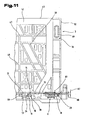
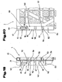
- FIGS. 8 to 11 is then one of the plates 2, 4 which form the transverse side walls of the container 1, shown in detail and described, wherein for similar parts as in the plates 3, 5, the same reference numerals are used.
- this plate 2 in turn has a reinforcing bar 42, which is formed by a hollow body and was prepared by a known from the prior art method, as already in the detailed description of the Fig. 4 to 7 was explained in detail.
- pivoting devices 10 are arranged, which are formed by connecting webs 12 of the end edge 13 distant pivot pin 11.
- These pivot pins 11 have the two end portions 18, 60, which project in the direction of the longitudinal extent of the plate 2 on both sides via the connecting web 12.
- a pivot pin pair 93, 94 is assigned over a width 90 in each case in the direction of narrow end faces 91, 92.
- Another pivot pin 11 is associated with the central region of the plate 2 in the region of the end edge 13.
- a distance 95 between the pivot pin 11 of the two pairs of pivot pins 93, 94 is less than a distance 96 between that in the central region of the plate second associated pivot pin 11 and the pivot pin 11 adjacent pivot pin 11 of the two pivot pin pairs 93, 94th
- the aforementioned reinforcing bracket 42 extends along the longitudinal end edge edge 45 of the plate 2, then extends on both sides of the plate 2 parallel to the narrow end faces 91, 92 and jumps on both sides of the plate 2 obliquely in the direction of the end edge 13 extending toward a center of the plate 2 and ends in the region of the edge strip 63 of the plate 2, wherein this reinforcing bar 42 or the end edge 13 facing end portions of the reinforcing bar 42 in the region of the distance 95 between the pivot pin 11 of the pivot pin pairs 93, 94 is arranged.
- the plate 2 similar to the plate 3 longitudinal members 47, 48, diagonal braces 50 and vertical support 49, whereby a better load transfer over the plate 2 is achieved in the plate 6 formed as a bottom.
- a very good spatial stiffening but above all a high vertical load through the plates 2, 4, are added.
- centering recesses 51 are again arranged, which can cooperate with corresponding centering projections in the plate 6 of the overlying container 1 forming the base. Since a relatively high introduction of force by the overlying container 1 occurs in this area, the two aligned diagonal supports 50 end approximately in the region of these ZentrierausEnglishept 51, the massively occurring forces evenly over the transverse side wall or on the additionally arranged longitudinal members 47, 48 and vertical supports 49 can be derived evenly in the trained as a bottom plate 6.
- the power dissipation in the plate 6 formed as a bottom is further improved in that the end edge 13 facing end portions of the reinforcing bracket 42 in the region of distances 95 between the pivot pin 11 of the pivot pin pairs 93, 94 end and so the derived via the reinforcing bar 42 force evenly can distribute to the two pivot pins 11 of the two pivot pin pairs 93, 94 and so overloading of a single pivot pin 11 and its end portions 18, 60 can be avoided.
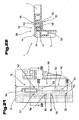
- the plate 2 and the plates 2, 4 now have in the region of their narrow end faces 91, 92 extending from the skirt 63 in the direction of the reinforcing bracket 42 and a thickness 97, the plates 2, 4 in the region between the reinforcing bracket 42 and Have pivoting device 10 - as this in the Fig. 9 is shown - projecting support or centering 98 to 102 on.
- These support or centering elements 98 to 102 act to improve the power dissipation and centering in the connecting region of the plates 2, 4 with the plates 3, 5 with the support or centering elements 66 to 68 of the stop strips 29 of the plates 3, 5 together, such as this will be detailed in the following description.
- the plates 2, 4 in the region of the narrow end faces 91, 92 a reduced thickness 103 compared to the thickness 103 on.
- the thickness 103 is compared to the thickness 34 by a thickness 104 of the stop bars 29 of the plates 3, 5 is less to intervene in an engagement of the stop strips 29 of the plates 3, 5 in the edge regions of the plates 2, 4 in one of the plates 2 to 5 locking position in the region of the narrow end faces 91, 92 of the plates 2, 4, the thickness 34 is not exceeded.
- connection receptacle of the connecting device 70 is arranged to receive the connecting element 69, wherein the more accurate design of this connecting device 70 in the following Description will be discussed in more detail.
- Each of the plates 2 to 5 has approximately the same thickness 34.
- an axis 59 of the pivot pin 11 extending in the plane of the inner surface 28 is arranged at a smaller distance from the inner surface 28 than half the thickness 34 of the individual plates 2 to 5.
- the thickness 34 of the individual plates 2 to 5 results from the height 62, around which the outer circumferential, the plates 2 to 5 limiting, edge strip 63 protrudes beyond an inner surface 28 opposite outer surface 64 of the plates 2 to 5, and the thickness 97 of the respective plate 2, 4.
- the stiffening of Plates 2 to 5 are within the, the plates 2 to 5 bounding edge strips 63, the already mentioned side members 47, 48, vertical beams 49 and diagonal braces 50, as best seen in the views of Fig. 4 . 6 . 8th . 10 and 11 visible, arranged. How further the Fig. 9 can be seen, the edge strip 63 is formed in the region of the opposite of the pivot pin 11 longitudinal end edge 45 as a hollow profile.
- the connecting web 12 is dimensioned such that a measure 87 between the end edge 13 and a facing this closest surface portion of the end portion 18 of the pivot pin 11 is slightly larger than a distance 88 between the end portion 18 and the end edge 13 facing surface of the Cladding element 20, wherein the distance 88 corresponds to a voltage applied to the cladding element 20 end portion 18 of a thickness 89 of the cladding element 20.
- these dimensions may also be different, so that depending on the forces acting on the plates 2 to 5, acting on the bottom forming plate 6 forces either either first additionally on the front edge 13 or the pivot limiter 53, and then on the respective other part are introduced into the bottom forming plate 6.
- the bottom forming plate 6 is shown in a front or side view. It can be seen that the plate 6 formed as a bottom for the plates 2, 4 and 3, 5 edge strips 16 having different heights.
- a total thickness 105 of the bottom and the edge strip 16 with the bearing housings 14 in the frontal region of the plate 6 and in the area for receiving the plates 2, 4 corresponds to a sum of a thickness 106 of the plate 6 plus a thickness 107 of the pivot pin 11 and a thickness 108 of the cladding element 20, wherein preferably the thickness 107 of the pivot pin 11 of the pivoting device 10 is equal to a diameter 109 of the pivot pin 11 receiving groove 17.
- the pivot pin 11 is disposed on the plates 2 to 5 in the plane of the inner surface 28 extending axis 59 of the pivot pin 11 at a smaller distance from the inner surface 28 of the plates 2 to 5 than half the thickness 34 of the individual plates 2 to 5.
- a total thickness 110 of the edge strips 16 with the bearing housings 14 for the plates 3, 5 is preferably higher by the thickness 34 of the plates 2, 4 than a total thickness 105 of the edge strips 16 with the bearing housings 14 in the region of the plates 2, 4.
- the plate 6 formed as a base has projecting webs 112 on a lower side 111 which is intended to serve for depositing the containers 1 on a substrate.
- an outer dimension 113 of the webs 112 extends in the side view of the plate 6 and an outer dimension 114 of the webs 112 in the end view of the plate 6, wherein the outer dimension 113 in approximately an inner width 115 between plates 2, 4 in their erected locked position - this in the Fig. 2 is illustrated and corresponds to an outer dimension 114 approximately at an inner width 116 between the plates 3, 5 in their vertical erected and locked position.
- the edge strip 16 for the plates 3, 5 by a measure 118 against the end edges 39 of the edge strips 16 for the plates 2, 4 before.
- This measure 118 corresponds approximately to the thickness 104 of the stop strips 29 of the plates 3, 5, whereby a flat end face of the folded into the transport position container 1 is achieved.
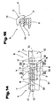
- FIGS. 14 to 18 is now the formation of a pivoting device 10 according to the invention with inserted into the groove 17 pivot pin 11, which has the end portions 18, 60 shown.
- the bearing housing 14 is designed here such that the pivot pin 11 is shown with its two end portions 18, 60 and the pivot pin 11, each with a plate 2 to 5 connecting connecting web 12.
- the end portion 18 of the pivot pin 11 has the front side, the conically extending guide surface 78, said guide surface 78 adjacent the retaining lug 19 of the groove 17 is arranged, which serves to receive the end portion 18 of the pivot pin 11.
- the plates 2 to 5 have in the region of the bottom plate 6 facing end edges 13 of the plates 2 to 5 pivoting devices 10 and are adjustably connected in their erected position and at least one parallel to a front edge 13 of a plate 2 to 5 extending pivot pin 11 is supported by the this facing end edge 13 of the plate 2 to 5 spaced over a connecting web 12 and in the groove 17 of another plate 6 is used.
- the groove 17 has a groove base 120, which is concave, wherein the groove 17 has two end portions 121, 122 and the end portion 122 is closed by a diameter 123 of the groove 17 through the retaining lug 19 and the cladding element 20 and a receiving chamber 124 forms for the end portion 18 of the pivot pin 11.
- a diameter 123 of the groove 17 is preferably equal to a diameter 107 of the pivot pin 11, whereby a play-free fit of the pivot pin 11 in the groove 17 and the closed by the cladding element 20 retaining lug 19 is ensured.
- the groove 17 is now arranged at least in some areas in a bearing housing 14, in a projecting over the plate 6 skirt 16 and has the open length 25, which corresponds at least to the length 26 of the pivot pin 11.
- a distance 125 between the holding lug 19 and the stop 27 is at least equal to a length 126 of the connecting web 12 measured in the direction of the longitudinal central axis 24 but not greater than the length 126 of the connecting web 12 plus the journal length 81 of the end region 18 of the latter projecting in the same direction Pivot pin 11 is.
- the pivotal connection between the groove 17 and the pivot pin 11 and thus between two plates 2 to 6 is now carried out as follows.
- the entire pivot pin 11 has a length 26 which is equal to or slightly smaller than an open length 25 of the groove 17 is formed, and so the pivot pin 11 can be inserted into the groove 17. This takes place in an angular position of the connecting web 12, wherein the position for assembling the pivoting device 10 should not correspond to the position of use of the container 1.
- a movement of the pivot pin 11 transversely to the longitudinal extension of the groove 17 is prevented by a diameter 123 of the groove 17 is equal to a diameter 107 of the pivot pin 11 and so the pivot pin 11 and the groove 17 have the same longitudinal central axis 24.
- the pivot pin 11 is inserted over the open length 25 of the groove 17 in the groove 17, the pivot pin 11 are guided in the grooves 17 such that a relative movement of the pivot pin 11 in the grooves 17 along the longitudinal central axis 24 in the direction of the holding projection 19 allows becomes.
- the pivot pin 11 is displaced in the direction of the end portion 122 of the groove 17, the end portion 18 of the pivot pin 11 penetrates into the receiving chamber 124 of the retaining projection 19 circumferentially closed by the cladding element 20, this process by the arrangement of the guide surface 78 on the end portion 18 of the pivot pin 11 can be substantially facilitated.
- the end portion 18 of the spigot 11 comes now to an inner end edge 128 of the receiving chamber 124 to the plant, but also a distance between them may be possible since the holding lug 19 facing end side 129 of the connecting web 12 on a connecting web 12 facing end surface 130th the holding approach 19 comes to rest and is guided by this, as the representation of Fig. 18 can be seen.
- an arc length 131 of the recess 21 is crucial to the degree of pivoting of the connecting web 12 and so the pivoting range of the pivot pin 11 and the connecting web 12 having plate 2 to 5 is limited by this recess. So it is possible in this advantageous embodiment, by other shaping, the arc length 131 of the recess 21 to reduce or increase, whereby a reduction or increase in the pivoting range of a plate 2 to 5 can be tuned.
- an opening width 133 of the groove 17 slightly smaller form the diameter 107 of the pivot pin 11, whereby the pivot pin 11 snaps into the groove 17 and an independent exit of the pivot pin 11, can be secured on the groove 17 avoided.
- FIG. 17 Now another variant for the groove 17 for receiving the pivot pin 11 is shown.
- the training largely corresponds to the presentation of the Fig. 16 , wherein in this case the cladding element 20 opposite a recess 134 is arranged, which is adapted to the enveloping circle of the pivot pin 11 and so the pivot pin 11 over its entire surface in this recess 134 rests.
- a height 135 of the groove 17 and the receiving chamber 124 is increased in the region of the longitudinal central axis 24.
- the longitudinal central axis 24 is offset from a means of the opening width 133 and so for removing the pivot pin 11 from the groove 17 by an amount 136, which corresponds to the depth of the recess 134, must be raised.
- the illustrated position of the pivot pin 11 or the connecting web 12 reflects the position of use of the pivoting device 10, i. the position at vertical position of the plates 2 to 5 to the plate 6 erected use position, again. In this position, the largest force is exerted on the pivoting devices 10 and the pivot pin 11 in stacked containers 1, whereby between the groove base 120 and this groove base 120 associated outer surface of the pivot pin 11 builds up a high surface pressure. This surface pressure counteracts a leakage of the pivot pin 11 from the groove 17, as it is due to adverse circumstances, such. by blows on the plates 2 to 5 from the outside, etc., could be caused.
- connection receptacle 137 which corresponds to the connecting element 69 has.
- This embodiment is not limited to the variant described here, but may be arranged in all corner regions of the container 1.
- the stop bar 29 of the plate 5 has, as already described above, on its side facing the longitudinal center of the plate 5, the support or centering elements 66 to 68. Between the support or centering element 66 and the longitudinal end side edge 45 of the plate 5, the connecting element 69 is now arranged. In contrast, the edge region of the plate 2, which forms a covering region 138 with the plate 5, has the connection receptacle 137 associated with it in a congruent arrangement with elastically deformable retention elements 139.
- the connecting element 69 is formed by a mushroom-like extension 140, with respect to which the connection receptacle 137 or the retaining elements 139 has projections 141 for engaging behind the mushroom-like extension 140.
- the connecting element 69 can form any shape or any angular position with respect to the vertical extent of the stop bar 29 and the connection receptacle 137 is arranged in congruent training in the edge region of the plate 2.
- a plurality of the height extension of the stop bar 29th distributed connecting elements 69 and connecting devices 70 are arranged so as to improve the connection of the two plates 2, 5 in its corner region.
- connection receptacle 137 To connect the connecting element 69 with the connection receptacle 137, the plate 5 or the plates 3, 5 is initially moved into a position extending approximately vertically to the plate 6, and then the plates 2, 4 are pivoted up into their position of use. If the connecting elements 69 now meet the connection receptacles 137, they engage with a conical guide surface 142 in a conical receptacle 143 of the connection receptacle 137.
- the conical guide surface 142 of the extension 140 now engages in the conically tapering receptacle 143 of the connection receptacle 137 and the retaining elements 139 opposite to the extension 140 are expanded by a force introduction via the projection 140, whereby an opening width 144 of the connection receptacle 137 is increased ,
- the advantage here is when a frontal width 145 of the extension 140 is lower one of this end face of the extension 140 facing opening width 146 of the retaining elements 139.
- This advantageous embodiment it is possible, before snapping the extension 140 in the connection receptacle 137 this in the correct position to center and so facilitate a connection between the plates 2, 4 with the plates 3, 5.
- this arrangement has validity for all possible forms of the connecting elements 69 or connecting receptacles 37, wherein the connecting elements 69 or connecting receptacles 137 can be circular, square or polygonal.
- the resilient configuration of the retaining elements 139 is achieved by the elasticity of the plastic material and by the arrangement of any number of recesses 147 along the retaining elements 139.
- the retaining elements 139 are extended opposite to the extension 140, wherein they slide along the guide surface 142 of the extension 140 and engage the extension 140 when the connection of the side walls 2, 5 and thus an automatic release the plate 2 is prevented by the plate 5.
- the elastically deformable design of the retaining elements 139 of the connecting receptacle 137 ensures that the connecting device 70 can be released again if necessary, wherein the force application in the opposite direction, as described above, must be applied.
- a conical guide surface can again be arranged on the retaining elements 139 on the side opposite the conical receptacle 143.
- the support or centering elements 66 to 68 and the support or centering 98 to 102 are on the stop bar 29 of the plate 5 and in the edge region of the plate 2, the support or centering elements 66 to 68 and the support or centering 98 to 102 arranged.
- the support or centering elements 66 to 68 and 98 to 102 in their assigned areas of the plates 2, 5 and 3, 4 abut each other in a plurality of mutually different spatial directions.
- the support or centering elements 66 to 68 and 98 to 102 may have any possible shape of the shape, but preferably be S-shaped or L-shaped, however, straight webs may also be used as support or centering elements 66 to 68 and 98 to 102.
- the support or centering elements 98, 99 form in the edge regions of the plates 2, 4 a support receptacle 148 for the in the locked state of the two plates 2, 5 between the support or centering elements 98, 99 engaging support or centering elements 66, 67 which are arranged on the stop bar 29 of the plate 5, from.
- a support receptacle 149 for the support or centering 99, 100 of the plate 2, 4.
- a further support receptacle 150 for a further support or centering element 151 on the stop bar 29 of the plates 3, 5.
- the support or centering elements 66 to 68 have transition regions 152 which extend parallel to a height extent of the plate 5 and are distanced from the inner surface 28 of the plate 5 by a distance 153.
- the distance 153 is equal to a thickness 154 of the skirt 63 of the plates 2, 4, whereby the transition areas 152 of the plate 3, 5 assigned Areas of the edge strip 63 of the plates 2, 4 form-fitting between the inner surface 28 and the transition regions 152 on or eino.
- FIGS. 23 and 24 now the overlapping areas of the support or centering elements 66 to 68 of the plate 5 with the support or centering elements 98 to 100 of the plate 2 are shown in detail.
- outer sides 157 of the support or centering elements 98 to 100 fit positively against outer sides 158 of the support or centering elements 66 to 68 of the stop bar 29.
- An advantage of such an embodiment is in this case when a height 159 of the support or centering elements 98 to 100 is equal to a height 160 of the support or centering elements 66 to 68, whereby the best possible load transfer on the outer sides 157, 158 is made possible. Furthermore, a desirable stability of the container 1 is substantially increased thereby.
- the outer sides 157, 158 in such a form as inclined surfaces, that they engage in the connected state of the plate 2 with the plate 5 in a corresponding manner.
- the support or centering 98 to 100 of the plate 2 tapering in the direction of the stop bar 29 of the plate 5 and, in contrast, the support or centering elements 66 to 68 of the stop bar 29 of the plate 5 also in the direction of the plate 2 tapered.
- the support or centering elements 66 to 68 are L-shaped and connect the transition regions 152 and the sub-regions 156 at right angles to the support or centering elements 66 to 68.
- this spatial form can be a much higher stability of the support or centering elements 66 to 68 reach, as is clear Fig. 19 is apparent.
- the plates 3, 5 in turn have in their upper end region or in the region of the longitudinal end side edge 45, the reinforcing bar 42, wherein the reinforcing bar 42 formed as a hollow profile on the side facing away from the inner surface 28 partially recesses 162 along the longitudinal extent of the reinforcing bar 42, which is along the longitudinal extent of the reinforcing bracket 42 form projections 163. Furthermore, the reinforcing bar 42 has further recesses 164 along its longitudinal extent, wherein a depth of these recesses 164 is greater than a wall thickness 165 of the hollow profile of the reinforcing bar 42.
- 5 are on the inner surface 28 opposite side of the plate 3 from the reinforcing bracket 42 in the direction of a reinforcing bar 166 extending over the longitudinal extension of the plates 3, 5 distributed reinforcing ribs 167 integrally formed on the plate 3 in that the reinforcing ribs 167 taper away from the reinforcing bar 42 in the direction of the inner surface 28 of the plate 3 and run parallel to the inner surface 28 of the plate 3 in an end region facing the reinforcing strip 166.
- the reinforcing strip 166 adjacent in the direction of the reinforcing bar 42 is a breakthrough 168 extending through the plate 3 and extending over the entire longitudinal extent of the plate 3 and limited by the stop strips 29 of the plate 3.
- This opening 168 is straddled by the reinforcing ribs 167 arranged between the reinforcing bar 42 and the reinforcing bar 166, whereby the stability of the plate 3, 5 is not reduced by the opening 168.
- the side walls forming plates 3, 5 overlap each other in their resting position on the bottom forming plate 6 transport position and a thickness 169 of the superimposed plates 3, 5 is not greater than the thickness 34 of a single one of the plates 2 to 5. Furthermore, an outer side surface 170 of the reinforcing bar 42 engages in a counter-running groove in the reinforcing bar 42 of the opposite plate 3, 5 a.
- the groove 17 is arranged at least in partial areas in a projecting over one of the plates 2 to 5 skirt 16 and an open length 25 which corresponds at least to the length 26 of the pivot pin 11 and in the area one of the side cheeks 22 of the groove 17 a pivoting portion of the connecting web 12 about a longitudinal central axis 24 of the groove 17 releasing extending in the radial direction recess 21 is arranged, which is limited in the direction of the longitudinal center axis 24 of the groove 17 by the retaining lug 19 and a stop 27 and a distance 125 between the retaining lug 19 and the stop 27 is at least equal to a parallel to the pivot pin 11 extending length 126 of the connecting web 12 but not greater than the sum of the length 126 of the connecting web 12 and a journal length 81 of the projecting beyond this in the same direction end region 18 of the pivot pin eleventh
- the connecting device 70 is formed by a plate 3, 5 fixedly arranged connecting element 69, which projects in the direction of the further plate 2, 4 and this on the further plate 2, 4, a connection receptacle 137 with elastic deformable retaining elements 139 is associated in a congruent arrangement.
- the support or centering elements 66 to 68, 151 and 98 to 102 are arranged in the plane of a plate 2 to 5 in a plurality of mutually different spatial directions.
Description
Die Erfindung bezieht sich auf einen Behälter, wie dieser im Oberbegriff des Anspruches 1 beschrieben ist.The invention relates to a container, as described in the preamble of
Ein solcher Behälter, bestehend aus mehreren Platten, wovon mehrere dieser Platten über Gelenksanordnungen verschwenkbar sind, ist aus der
Die
Auch sind derartige Behälter unter anderem aus der
Zum Transport der Güter werden die die Seitenwände bildenden Platten in etwa in eine rechtwinkelig zum Boden verlaufende Lage hochgeschwenkt und untereinander arretiert.To transport the goods, the plates forming the side walls are swung up approximately in a position running at right angles to the ground and locked together.
Die Schwenkvorrichtungen zwischen den einzelnen Platten werden durch Schwenkzapfen gebildet, die über Verbindungsstege distanziert von den Stirnkanten der einzelnen Platten gehalten sind und in Nuten der anderen Platte einrasten. Durch eine Relativverschiebung der einzelnen Platten zueinander in Richtung der Längsachse der Schwenkzapfen ist es bei einigen dieser Behälter möglich, die Platten voneinander zu trennen.The pivoting devices between the individual plates are formed by pivot pins, which are held by connecting webs distanced from the end edges of the individual plates and engage in grooves of the other plate. By a relative displacement of the individual plates to each other in the direction of the longitudinal axis of the pivot pin, it is possible for some of these containers to separate the plates from each other.
Weiters ist auch ein Behälter gemäß der
Bei all den vorgenannten Behältern konnten diese jedoch nicht alle an sie gestellten Anforderungen hinsichtlich der erforderlichen Festigkeitseigenschaften und der ausreichenden Belastbarkeit der Verriegelungselemente erfüllen.In all the aforementioned containers, however, these could not meet all the requirements placed on them with regard to the required strength properties and sufficient resilience of the locking elements.
Der vorliegenden Erfindung liegt daher die Aufgabe zugrunde, einen Behälter-zuschaffen, der höheren Beanspruchungen durch das damit transportierte Gut als auch Beanspruchungen, die von außen auf den Behälter während des Transportes des Gutes eintreten, einen hohen Widerstand entgegensetzen und auch bei übereinandergestapelten Behältern eine ausreichende Tätigkeit zur Aufnahme des Gewichtes des darübergelagerten Behälters aufweist.The present invention is therefore based on the object, a container-zaffaffen, the higher stresses by the goods transported so as well as stresses that occur from the outside of the container during the transport of the goods, a high resistance oppose and even with stacked containers sufficient Activity for receiving the weight of the overlying container.
Diese Aufgabe der Erfindung wird durch die Merkmale im Kennzeichenteil der Ansprüche 1 bis 4 gelöst.This object of the invention is achieved by the features in the characterizing part of
Vorteilhaft ist bei der in Anspruch 1 angegebenen Lösung, daß durch die Anordnung von Randleisten die Tragfähigkeit der den Boden bildenden Platte entsprechend verstärkt wird und überdies die Gelenkanordnungen über die Oberfläche des Bodens hinaus verlagert werden, sodaß ein Einsetzen und Lösen der die Seitenwände bildenden Platten vom Boden in horizontaler auf den Boden eingeschränkter Lage möglich wird und andererseits im aufgerichteten Zustand die Schwenkzapfen nach außen hin geschützt und abgedeckt angeordnet sein können. Dadurch wird ein besserer Schutz dieser heiklen und sensiblen Schwenkzapfen der Schwenkvorrichtungen, beispielsweise durch Gabelstaplerzinken oder zu eng aneinandergestellte Behälter oder bei Schlägen durch die Bordwand eines Kraftfahrzeuges verringert.It is advantageous in the solution specified in
Bei der Ausführungsvariante nach Anspruch 2 wird mit Vorteil erreicht, daß eine Mindestvorspannung der Schwenkzapfen gegenüber den diese aufnehmenden Lagerbereichen in der Nut, also der weiteren Platte erzielt wird, sodaß auch bei Schlagbeanspruchung und Vibrationen eine ausreichende Führung und Halterung des Schwenkzapfens in der Nut erzielt werden kann. Dazu kommt, daß gleichzeitig aber unerwünschte Überbeanspruchungen der Schwenkzapfen, die zu einem Bruch oder Verformung derselben führen könnten, mit Sicherheit ausgeschaltet sind. Dies ermöglicht eine hohe vertikale Belastung auch durch übereinandergestapelte Behälter und eine höhere Haltbarkeit der Schwenkzapfen in den Nuten bei gegen den Innenraum des Behälters von außen her die Seitenwände bildenden Platten einwirkenden Schlägen.In the embodiment according to
Die weitere Ausführungsvariante nach Anspruch 3 ermöglicht in überraschend vorteilhafter Weise ein in der Aufstellrichtung erfolgendes Zusammenschnappen und Einrasten der gegeneinander verstellbaren Platten, wobei durch die Anordnung dieser Verbindungsaufnahmen mit elastisch verformbaren Rückhalteelementen eine Führung und Abstützung in unterschiedlichen Raumrichtungen erreicht wird, die ein Ausbeulen der im Eckbereich miteinander verbundenen Platten in vorteilhafter Weise entgegenwirkt.The further embodiment according to
Die weitere für sich eigenständige Lösung nach Anspruch 4 ermöglicht eine Verzahnung der aneinanderstoßenden, aufgerichteten Platten in einer sich etwa senkrecht zu der den Boden bildenden Platte befindlichen Platten in unterschiedlichen Raumrichtungen, sodaß auch bei hohen vertikalen oder horizontalen Belastungen ein Ausweichen der aneinanderstoßenden Platten in verschiedenen Raumrichtungen verhindert wird und damit auch bei extremer Belastung durch das aufzunehmende Gut oder durch von außen einwirkende Kräfte von Beförderungsmitteln oder dgl. keine Schäden am Behälter entstehen.The further stand-alone solution according to
Weitere vorteilhafte Ausbildungen sind in den Ansprüchen 5 bis 68 gekennzeichnet, wobei die dabei erzielbaren Vorteile der detaillierten Beschreibung zu entnehmen.Further advantageous embodiments are characterized in the
Die Erfindung wird im nachfolgenden anhand der in den Zeichnungen dargestellten Ausführungsbeispiele näher erläutert.The invention will be explained in more detail below with reference to the embodiments illustrated in the drawings.
Es zeigen:
- Fig. 1
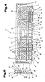
- einen erfindungsgemäßen Behälter in Schrägansicht mit in paralleler Lage zueinander angeordneten, den Boden und Seitenwände bildenden Platten in vereinfachter und schematischer Darstellung;
- Fig. 2
- den Behälter nach
Fig. 1 in schaubildlicher Darstellung mit in Gebrauchsstellung hochgeklappten Seitenwände bildenden Platten; - Fig. 3
- einen erfindungsgemäßen Behälter in einer anderen Transportstellung mit einwärts auf die den Boden bildende Platte abgeklappten, die Seitenwände bildenden Platten;
- Fig. 4
- eine Seitenwand bildende Platte des erfindungsgemäßen Behälters in Seitenansicht;
- Fig. 5
- einen stirnseitigen Endteil der Platte in Stirnansicht geschnitten gemäß den Linien V - V in
Fig. 4 ; - Fig. 6
- die die Seitenwand bildende Platte in Seitenansicht in ihrer zu der den Boden bildenden Platte unter 90° hochgeschwenkter Gebrauchsstellung;
- Fig. 7
- einen Teil der die Seitenwand bildenden Platte in einem Stirnendbereich derselben in vergrößertem Maßstab in Seitenansicht;
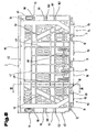
- Fig. 8
- eine eine Stirnwand des Behälters bildende Platte in Seitenansicht;
- Fig. 9
- die die Stirnwand bildende Platte in Stirnansicht geschnitten gemäß den Linien IX - IX in
Fig. 8 ; - Fig. 10
- die die Stirnwand bildende Platte in gegenüber ihrer der den Boden bildenden Platte um 90° hochgeschwenkter Stellung in Seitenansicht bei entfernten die Längsseitenwände bildenden Platten;
- Fig. 11
- einen Endbereich der eine Stirnwand des Behälters bildenden Platte in vergrößertem Maßstab;
- Fig. 12
- die den Boden bildende Platte in Stirnansicht bei entfernten die Seitenwänden bildenden Platten, gemäß Pfeil XII in
Fig. 2 ; - Fig. 13
- die den Boden bildende Platte ein Seitenansicht gemäß Pfeil XIII in
Fig. 2 ; - Fig. 14
- ein Schwenklager eines erfindungsgemäßen Behälters zwischen einer einen Boden und einer eine Seitenwand bildende Platte in Seitenansicht mit eingesetztem Schwenkzapfen geschnitten gemäß den Linien XIV - XIV in
Fig. 3 ; - Fig. 15
- das Schwenklager in Stirnansicht geschnitten gemäß den Pfeilen XV - XV in
Fig. 14 ; - Fig. 16
- das Schwenklager zwischen zwei Platten in Stirnansicht geschnitten gemäß den Linien XVI - XVI in
Fig. 14 ; - Fig. 17
- eine Ausführungsvariante der Ausbildung des Schwenklagers in Stirnansicht geschnitten nach
Fig. 16 ; - Fig. 18
- eine Seitenansicht auf ein Schwenklager eines erfindungsgemäßen Behälters zwischen einer einen Boden und einer eine Seitenwand bildende Platte in Seitenansicht geschnitten nach
Fig. 14 , bei in den Halteeinsatz eingeschobenen Endbereich des Schwenkzapfens; - Fig. 19
- einen stirnseitigen Endteil einer Platte in Stirnansicht geschnitten;
- Fig. 20
- einen Teilbereich einer weiteren Platte in der Seitenansicht;
- Fig. 21
- den Eckbereich zwischen zwei vertikal zu einer einen Boden bildenden Platte aufgerichteten Platten, in Gebrauchsstellung;
- Fig. 22
- den Eckbereich nach
Fig. 21 geschnitten gemäß den Linien XXII - XXII inFig. 21 ; - Fig. 23
- einen Teilbereich des Eckbereiches nach
Fig. 21 , geschnitten gemäß den Linien XXIII - XXIII inFig. 21 ; - Fig. 24
- eine weitere Ausführungsform des Teilbereiches nach
Fig. 23 ; - Fig. 25
- ein Überlappungsbereich einer Platte in Stirnansicht geschnitten;
- Fig. 26
- den Überlappungsbereich mit ineinandergeklappten Platten in Stirnansicht geschnitten.
- Fig. 1
- a container according to the invention in an oblique view with arranged in parallel to each other, the bottom and side walls forming plates in a simplified and schematic representation;
- Fig. 2
- the container after
Fig. 1 in a perspective view with folded up in use position side walls forming plates; - Fig. 3
- a container according to the invention in another transport position with inwardly folded on the bottom plate forming the side walls forming plates;
- Fig. 4
- a side wall forming plate of the container according to the invention in side view;
- Fig. 5
- a front end portion of the plate in front view cut according to the lines V - V in
Fig. 4 ; - Fig. 6
- the side wall forming plate in side view in her to the bottom forming plate at 90 ° swung-up position of use;
- Fig. 7
- a part of the side wall forming plate in a front end region thereof in an enlarged scale in side view;
- Fig. 8
- a front wall of the container forming a plate in side view;
- Fig. 9
- the front wall forming plate cut in front view according to the lines IX - IX in
Fig. 8 ; - Fig. 10
- the front wall forming plate in relation to its
bottom forming plate 90 ° swung-up position in side view at the longitudinal side walls forming plates; - Fig. 11
- an end portion of the plate forming an end wall of the container on an enlarged scale;
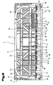
- Fig. 12
- the plate forming the bottom in front view with plates forming the side walls, according to arrow XII in
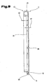
Fig. 2 ; - Fig. 13
- the bottom forming plate is a side view according to arrow XIII in
Fig. 2 ; - Fig. 14
- a pivot bearing of a container according to the invention between a bottom and a side wall forming plate in side view with inserted pivot pin cut according to the lines XIV - XIV in
Fig. 3 ; - Fig. 15
- the pivot bearing cut in front view according to the arrows XV - XV in
Fig. 14 ; - Fig. 16
- the pivot bearing between two panels cut in front view according to the lines XVI - XVI in
Fig. 14 ; - Fig. 17
- an embodiment of the training of the pivot bearing cut in front view after
Fig. 16 ; - Fig. 18
- a side view of a pivot bearing of a container according to the invention between a bottom and a side wall forming plate cut in side view
Fig. 14 , with inserted into the holding insert end portion of the pivot pin; - Fig. 19
- a front end portion of a plate cut in front view;
- Fig. 20
- a portion of another plate in the side view;
- Fig. 21
- the corner region between two vertically upright to a plate forming a bottom plate, in the position of use;
- Fig. 22
- the corner area
Fig. 21 cut according to the lines XXII - XXII inFig. 21 ; - Fig. 23
- a partial area of the corner area
Fig. 21 , cut according to the lines XXIII - XXIII inFig. 21 ; - Fig. 24
- a further embodiment of the subsection after
Fig. 23 ; - Fig. 25
- an overlapping area of a panel cut in front view;
- Fig. 26
- cut the overlap area with panels folded into each other in front view.
Einführend sei festgehalten, daß in den unterschiedlich beschriebenen Ausführungsformen gleiche Teile mit gleichen Bezugszeichen bzw. gleichen Bauteilbezeichnungen versehen werden, wobei die in der gesamten Beschreibung enthaltenen Offenbarungen sinngemäß auf gleiche Teile mit gleichen Bezugszeichen bzw. gleichen Bauteilbezeichnungen übertragen werden können. Auch sind die in der Beschreibung gewählten Lageangaben, wie z.B. oben, unten, seitlich usw. auf die unmittelbar beschriebene sowie dargestellte Figur bezogen und sind bei einer Lageänderung sinngemäß auf die neue Lage zu übertragen. Weiters können auch Einzelmerkmale oder Merkmalskombinationen aus den gezeigten und beschriebenen unterschiedlichen Ausführungsbeispielen für sich eigenständige, erfinderische oder erfindungsgemäße Lösungen darstellen.By way of introduction, it should be noted that in the differently described embodiments, the same parts are provided with the same reference numerals or the same component names, wherein the disclosures contained in the entire description can be mutatis mutandis to the same parts with the same reference numerals and component names. Also, the location information chosen in the description, such as top, bottom, side, etc. related to the immediately described and illustrated figure and are to be transferred to the new situation mutatis mutandis when a change in position. Furthermore, individual features or combinations of features from the different exemplary embodiments shown and described can also represent independent, inventive or inventive solutions.
In den
Der Behälter 1 besteht aus mehreren, insbesondere vier oder mehr Platten 2 bis 6, wobei bei dem abgebildeten Behälter mit einer rechteckigen Grundfläche im Gegensatz zu einem solchem mit einer dreieckigen Grundfläche fünf Platten 2 bis 6 angeordnet sind.The
Die Platte 6 bildet hierbei einen Boden und die Platten 2 und 4 bilden Stirnseitenwände und die Platten 3 und 5 Längsseitenwände. Diese Bezeichnung wurde nur deshalb gewählt, da der Boden, nämlich die Platte 6, eine Rechteckfläche bildet. Ist der Boden quadratisch, weisen selbstverständlich alle vier die Seitenwände bildenden Platten 2 bis 5 annähernd die gleiche Länge auf.The
Die einzelnen Platten 2 bis 6 können beliebig ausgestaltet sein und beispielsweise durch eine Fachwerkkonstruktion, eine Holmkonstruktion oder eine Platte mit einoder beidseitig vorspringenden Verstärkungsrippen gebildet sein.The
Im vorliegenden Ausführungsbeispiel ist lediglich beispielhaft aufgezeigt, daß jede der Platten 2 bis 6 auf denen einander zugewandten Oberflächen ebenflächig mit einer geringen Anzahl von Durchbrüchen 7, z.B. zur Belüftung eines Innenraums 8, versehen ist. Unter anderem können aber auch Ausschnitte 9, die als Handgriffe ausgebildet und verwendbar sind, in den Platten 2 bis 5 angeordnet sein.In the present embodiment, it is shown, by way of example only, that each of the
Die Ausführung, bei der die einander zugewendeten Oberflächen der Platten 2 bis 6 glatt und ohne Verrippung ausgebildet sind, hat den Vorteil, daß Beschädigungen der zu transportierenden Nahrungsmittel durch vorspringende Teile verhindert werden kann und andererseits eine gute Reinigung nach dem Gebrauch möglich ist.The embodiment in which the mutually facing surfaces of the
Um ein möglichst günstiges Verhältnis zwischen dem Volumen im Transportzustand, in dem der Behälter 1 leer ist, und dem Gebrauchszustand, in dem der Behälter 1 mit Waren oder Gegenständen bzw. Lebensmitteln befüllt ist, zu erreichen, sind die Platten 2 bis 5 an mit der den Boden bildenden Platte 6 über Schwenkvorrichtungen 10 verbunden.In order to achieve the best possible ratio between the volume in the transport state in which the
Diese Schwenkvorrichtungen 10 bestehen aus einem Schwenkzapfen 11, der über einen Verbindungssteg 12 distanziert von einer diesem zugewandten Stirnkante 13 der Platten 2 bis 5 feststehend angeordnet ist. Dieser Schwenkzapfen 12 ist in einem Lagergehäuse 14 bedarfsweise herausnehmbar schwenkbar gelagert.These pivoting
Dieses Lagergehäuse 14 wird durch über eine innere Oberfläche 15 im umlaufenden Randbereich vorspringende Randleisten 16 gebildet, in der zur Aufnahme der Schwenkzapfen 11 über eine Teillänge der jeweiligen Platte im Abstand voneinander angeordnet, Nuten 17 vorgesehen sind.This bearing
Die Nuten 17 sind in Richtung der gegenüberliegenden Seitenwand bzw. Stirnseitenwand geöffnet, sodaß die Schwenkzapfen 11 bei in etwa parallel zum Boden verstellter Lage der die Seitenwände bildenden Platten 2 bis 5 diese in die vertieften Nuten 17 eingesetzt bzw. aus diesen entfernt werden können. Dieses Einsetzen und Entfernen kann durch elastisches Verformen von Arretierzapfen oder Arretierflächen erfolgen, ist dies aber nicht zwingend erforderlich.The
Durch eine Relativverschiebung jeder einzelnen Platte 2 bis 5 zu der den Boden bildenden Platte 6 jeweils in Längsrichtung der zugeordneten Stirnkante 13 der Platte 6 wird einer von zwei über den Verbindungssteg 12 vorragenden Endbereiche 18 des Schwenkzapfens 11 in einen einen Halteansatz 19 bildenden Teil der Nut 17 eingeschoben.By a relative displacement of each
Dieser Halteansatz 19 wird dadurch gebildet, daß ein Teil der Nut 17 durch ein Verkleidungselement 20 abgedeckt ist.This retaining
Bei in den Halteansatz 19 eingeschobenem Endbereich 18 des Schwenkzapfens 11 kommt der Verbindungssteg 12 in eine durch eine Ausnehmung 21 in einer die Nut 17 bildenden Seitenwange 22 und gegebenenfalls zumindest einen Teil einer Basisplatte 23 angeordneten Ausnehmung 21, die eine parallel zur Längsrichtung der Schwenkzapfen 11 verlaufende Länge aufweist, die zumindest einer in der gleichen Richtung gemessenen Breite des Verbindungssteges 12 entspricht. Diese Ausnehmung 21 erstreckt sich über einen Schwenkbereich von zumindest 90°, bezogen auf die Längsmittelachse 24 der Schwenkzapfen 11.When inserted into the holding
Eine zum Mittelbereich der den Boden bildenden Platte 6 hingewandte offene Länge 25 der Nut 17 ist gleich oder geringfügig größer als eine Länge 26 des Schwenkzapfens 11.An
Durch die Gestaltung der Ausnehmungen 21 in Verbindung mit dem Schwenkzapfen 11 und den Verbindungsstegen 12 ist es nunmehr möglich, die Platten 2 bis 5, also die die Stirnseiten bildenden Platten 2 und 4 und jene die Längsseiten bildenden Platten 3 und 5 aus einer flach am Boden aufliegenden - nach innen geklappten Transportstellung - in eine um 180° nach außen, die den Boden bildende Platte 6 überragende, in etwa parallel zu dieser - Transport- oder Reinigungsstellung - nach auswärts zu verschwenken, sodaß sie außerhalb der umlaufenden Stirnseitenkante der den Boden bildenden Platte 6 zum liegen kommen.Due to the design of the
Die Gebrauchsstellung der einzelnen Platten 2 bis 5 relativ zu der den Boden bildenden Platte 6 befindet sich zwischen der parallel zur Platte 6 verlaufenden nach außen bzw. nach innen verschwenkten Lage, in welcher sie senkrecht zur Platte 6 ausgerichtet sind und mit dieser einen Winkel von 90° zwischen sich und der Platte 6 einschließen.The position of use of the
Zur Führung der Platten 2 bis 5 in ihrer Relativlage zur Platte 6 in parallel zueinander verlaufenden Stirnlängsseitenkanten der Platten 2 bis 5 verlaufender Richtung ist über einen Großteil der Schwenkbewegung der Verbindungssteg 12 in der Ausnehmung 21 zwischen dem Halteansatz 19 und einem gegenüberliegenden Anschlag 27 geführt.To guide the
Die Nut 17 weist einen in etwa U- bzw. C-förmigen Querschnitt auf, wobei eine symmetrisch zwischen den Schenkeln verlaufende Hochachse unter einem Winkel von 5° bis 25°, bevorzugt 8° bis 20°, zur Oberfläche des Bodens derart geneigt verläuft, daß sie zum Mittelbereich der den Boden bildenden Platte 6 ansteigt. Über diesen Winkelbereich ist eine Relativverschiebung zwischen der Platte 6 und den Platten 2 bis 5 sowie den Platten 3 und 5 möglich, sodaß diese über senkrecht zu ihrer Innenfläche 28 vorragende Anschlagleisten 29 geführt sind, in deren Schwenkbereich die den die Stirnseitenwände bildenden Platten 2, 4 zugewandten Stirnkanten 30, 31 übergreifen und daher eine Relativverschiebung zwischen den Platten 3, 5 und 6 verhindern.The
Selbstverständlich ist es hierbei auch möglich, daß diese Anschlagleisten 29 in ihrer auf die Platte 6 eingeklappten Lage, die parallel zu den Stirnkanten 30 verlaufenden Stirnkanten 32, 33 der die Querseitenwände bildenden Platten 2, 4 übergreifen.Of course, it is also possible that these stop strips 29 in their folded onto the
Selbstverständlich ist es auch möglich, die Anschlagleisten 29 anstelle der Anordnung auf den die Längsseitenwände bildenden Platten 3, 5 auf den die Querseitenwände bildenden Platten 2, 4 anzuordnen, sodaß diese gegengleich diese die Längsseitenwände 3, 5 bzw. die parallel zu diesen verlaufenden Stirnseitenkanten der den Boden bildenden Platte 6 übergreifen.Of course, it is also possible to arrange the stop bars 29 instead of the arrangement on the longitudinal side
Sind dagegen, wie beim vorliegend gezeigten Ausführungsbeispiel, die Anschlagleisten 29 auf den die Längsseitenwände bildenden Platten 3, 5 angeordnet, so sind die Längsmittelachsen 24 der Nuten 17 bzw. der Schwenkzapfen 11 in einem eine Dicke 34 dem der Platten 2, 4 entsprechenden in
Dementsprechend ist eine Länge 35 gleich oder geringfügig kleiner als eine Innenweite 36 zwischen den einander zugewandten Seitenflächen der Lagergehäuse 14 zur Aufnahme der Schwenkzapfen 11 der die Längsseitenwände bildenden Platten 3 und 5. Des weiteren ist auch eine Innenweite 37 zwischen den Anschlagleisten 29 jeder der die Längsseitenwände bildenden Platten 3 und 5 gleich oder geringfügig größer als eine maximale Distanz 38 zwischen voneinander abgewendeten Stirnkanten 39 der Lagergehäuse 14 zur Aufnahme der Schwenkzapfen 11 der Querseitenwände bildenden Platten 2 und 4.Accordingly, a
Gleichermaßen ist auch eine Höhe 40, über die die Anschlagleisten 29 senkrecht über die Innenfläche 28 der die Längsseitenwände bildenden Platten 3, 5 nach oben vorragen, gleich oder kleiner als eine Dicke 34 der die Querseitenwand bildenden Platte 2, 4 zuzüglich einer in
Während nun anhand der
In den
So weist diese Platte 3 einen Verstärkungsbügel 42 auf, der durch einen Hohlkörper gebildet ist. Dieser Verstärkungsbügel 42 verläuft annähernd entlang von Schmalstirnseiten 43, 44 von der Stirnkante 13 in Richtung einer Längsstirnseitenkante 45.Thus, this
Zur verbesserten Krafteinleitung bei übereinandergestapelten Behältern 1 ist es zweckmäßig, wenn die vertikal verlaufenden Teilbereiche des Verstärkungsbügels 42 über Bogenelemente mit den horizontalen Teilbereichen des Verstärkungsbügels 42 verbunden sind. Gleichermaßen ist es vorteilhaft, wenn zur Verstärkung der benachbarten Teilbereiche der Seitenwände der Verstärkungsbügel 42 nur über einen Teilbereich einer Höhe 46 der Platte 3 zumindest um die Stärke des Eckstehers in Richtung des Mittellängsbereiches versetzt bzw. zurückspringend angeordnet ist.For improved introduction of force when stacked
Der Verstärkungsbügel 42 besteht aus einem Kunststoffhohlprofil. Dieses Kunststoffhohlprofil kann bevorzugt durch einen Spritzvorgang und nachträgliches Ausblasen der Seele des Spritzgußteils, solange sich das Kunststoffmaterial in dem Zentralbereich noch im flüssigen bzw. plastischen Zustand befindet, in einem Arbeitsgang mit den übrigen Teilen der Platte 3 bzw. 5 hergestellt werden. Durch die Anlenkung von weiteren stabförmigen Längsträgern 47, 48 und Vertikalträgern 49 sowie Diagonalstützelemente 50 kann eine sehr gute räumliche Aussteifung, aber vor allem eine sehr hohe Vertikallast durch diese Platten 3, 5 aufgenommen werden.The reinforcing
Interessant ist hierbei, daß im Bereich der Längsseitenkante 45 Zentrierausnehmungen 51 angeordnet sind, die mit entsprechenden Zentriervorsprüngen 52 in der den Boden bildenden Platte 6 des darüberliegenden Behälters 1 zusammenwirken können. Da in diesem Bereich dann auch eine relativ hohe Krafteinleitung einsetzt, enden die beiden aufeinander zugerichteten Diagonalstützen 50 etwa in diesem Bereich, um die dort massiv auftretenden Kräfte gleichmäßig über die Längsseitenwand 3, 5 bzw. die einzelnen Längsträger 47, 48 und Vertikalstützen 49 zwischen dem Verstärkungsbügel 42 und den Schwenkvorrichtungen 10, insbesondere auch gegen Ausbeulung, zu versteifen.It is interesting that in the region of the
Um eine hohe Festigkeit und Widerstandfähigkeit der Schwenkvorrichtungen 10 zu erreichen, ist es auch vorteilhaft, wenn eine höhere Anzahl von Schwenkzapfen 11 über die Länge der Stirnkante 13 der Platte 3, 5 verteilt angeordnet sind.In order to achieve a high strength and resistance of the
So hat es sich als vorteilhaft erwiesen, die Schwenkvorrichtungen 10 jeweils paarweise nebeneinander anzuordnen und zwischen jeweils einem Paar der Schwenkvorrichtungen 10 befindet sich dann ein Schwenkbegrenzer 53.Thus, it has proved to be advantageous to arrange the
Die Aufgabe dieses Schwenkbegrenzers 53 liegt darin, beim Aufstellen der die Längsseitenwände bildenden Platten 3, 5, aber eventuell auch der Platten 2, 4, ein Verbleiben der Platten 2 bis 5 in ihrer aufgerichteten Stellung zu erzielen. Eine Aufstandsfläche 54 dieser Schwenkbegrenzer 53 dient auch als Überlastsicherung für die Schwenkvorrichtungen 10. Werden nämlich die Schwenkvorrichtungen 10 mit einer nicht vorgeplanten höheren Belastung beaufschlagt, so können sich die Aufstandsflächen 54 auf den diesen zugeordneten gegenüberliegenden Stützflächen 55 auf der einen Boden bildenden Platte 6 abstützen und damit die maximale auf die Schwenkvorrichtung 10 bzw. deren Schwenkzapfen 11 einwirkende Belastung verringern.The object of this pivoting
Durch diese über die Schwenkvorrichtungen 10 übertragene Grundbelastung der auf die Platten 2 bis 5 einwirkenden Vertikallasten wird andererseits eine hohe Flächenpressung zumindest zwischen den Endbereichen 18 des Schwenkzapfens 11 und dem Lagergehäuse 14 bzw. der Nut 17 erzielt, die auch bei starken gegen die die Seitenwände bildenden Platten 3 bzw. 5 gerichteten Schlägen ein Austreten der freiliegenden Endbereiche 18 des Schwenkzapfens 11 aus den diesen zugeordneten Nuten 17 verhindert.On the other hand, a high surface pressure is achieved at least between the
Dadurch, daß eine Seitenkante 56 der in etwa rechteckförmigen Aufstandsfläche 54 über den diese tangierenden Hüllkreis mit einem durch die Längsmittelachse 24 der Schwenkzapfen 11 gebildeten Hüllfläche 57 vorragt, bedarf es zur Überwindung dieser mechanischen Sperre eines zusätzlichen Kraftaufwandes. Andererseits verhindert diese Sperre aber auch dann, wenn die Platten 3, 5, zweckmäßigerweise natürlich auch die Platten 2, 4 in einer etwa vertikalen Lage zu der den Boden bildenden Platte 6 angeordnet sind, daß ein Zurückklappen der Seitenwände von sich aus in eine nach innen bzw. nach außen geklappte Transportlage erschwert wird und somit beim Aufstellen der Platten 2 bis 5, insbesondere 3 und 5, diese in eine in etwa zu deren Boden bildenden Platte 6 vertikalen Lage fixiert sind, sodaß danach die Querseitenwände, die durch die Platten 2 und 4 gebildet sind, in einem Arbeitsgang aufgerichtet werden können.Characterized in that a
Dadurch, daß die Aufstandsflächen 54 der Schwenkbegrenzer 53 in einem geringfügigen Abstand 58 oberhalb der diesen zugeordneten Stützflächen 55 der den Boden bildenden Platte 6 angeordnet sind, behindern diese beim Aufstellen der Platten 2 bis 5 des noch nicht befüllten Behälters 1 die Aufschwenkbewegung nur geringfügig. Beim Aufstellen bzw. Aufschwenken der Platten 2 bis 5 laufen die Seitenkanten 56 auf der Aufstandsfläche 54 auf, und werden nun aufgrund der vorspringenden Seitenkanten 56 die Platten 2 bis 5 unter elastischer Verformung quer zu einer Achse 59 der Endbereiche 18, 60 um jenes Ausmaß 61 und das der Seitenkante 56 über welches die Hüllfläche 57 vorragt angehoben, sodaß die Platten 2 bis 5 in eine zur Platte 6 etwa rechtwinkelige Stellung hochgeschwenkt werden können, in der sich die Aufstandsfläche 54 in einer zur Stützfläche 55 parallel, und von dieser geringfügig der Höhe nach distanzierten Lage befindet. Dadurch können die Platten 2 bis 5 um einen geringfügigen Winkelbereich um die Längsachse 24 der Schwenkzapfen 11 verschwenkt werden, können jedoch nicht in ihre zur Platte 6 parallelen, flachen Lage auf der Platte 6 oder seitlich der Platte 6 zurückfallen. Dies erleichtert das Aufrichten der, die Querseitenwände bildende Platten 2, 4 und deren Verriegelung mit den Platten 3,5. Gleichzeitig wird durch diese Auslegung eine Überbeanspruchung der elastisch verformbaren Endbereiche 18 der Schwenkzapfen 11 verhindert.Characterized in that the contact surfaces 54 of the
Jede der Platten 2 bis 5 weist eine in etwa gleiche Dicke 34 auf. Bevorzugt ist dabei eine, in der Ebene der Innenfläche 28 verlaufende, Achse 59 des Schwenkzapfens 11, in einem größeren Abstand von der Innenfläche 28 angeordnet als die Hälfte der Dicke 34 der einzelnen Platten 2 bis 5. Die Dicke 34 der einzelnen Platten 2 bis 5 ergibt sich aus einer Höhe 62, um die eine außen umlaufende, die Platten 2 bis 5 begrenzende, Randleiste 63 über eine der Innenfläche 28 gegenüberliegende Außenfläche 64 der Platten 2 bis 5 vorragt, sowie einer Dicke 65 der jeweiligen Platte 2 bis 5. Zur Versteifung der Platten 2 bis 6 sind innerhalb der, die Platten umgrenzenden, Randleisten 63 die bereits einleitend genannten Längsträger 47, 48, Vertikalträger 49 und Diagonalstützen 50, wie am besten aus den Ansichten der
Während nun die Randleisten 63 über die Außenfläche 64 der Platten 2 bis 6 vorragen, ragen bei den Platten 3 und 5, die die Längsseitenwände bilden, im Bereich der Schmalstirnseiten 43, 44 Anschlagleisten 29 um die Höhe 40 vor, wie dies bereits anhand der
Des weiteren ist ein Verbindungselement 69 einer Verbindungsvorrichtung 70 zum lösbaren Verbinden der Platten 2, 4 mit den Platten 3, 5 in ihrer aufgerichteten, etwa senkrecht zur Platte 6 verlaufenden Lage angeordnet.Furthermore, a connecting
Die Detailausführung dieser Verbindungsvorrichtung 70 wird anhand von Detaildarstellungen in der Folge noch näher erläutert.The details of this
Wie weiters aus der Schnittdarstellung in
Weiters ist aus den Darstellungen in den
Dazu kommt, daß die größere Länge der Schwenkbegrenzer 53 im Bereich der Schmalstirnseiten 43, 44 ein Zurückfallen der Platten 2 bis 5 besser verhindert, da die Platten in den Eckbereichen, aufgrund eventuell exzentrisch vorragender Gewichtsteile, eher die Neigung haben nach innen zu klappen, nicht zuletzt durch die Anordnung der vorragenden Anschlagleisten 29 mit den Stütz- bzw. Zentrierelementen 66 bis 68.In addition, the greater length of the
Wie insbesondere der vergrößerten Darstellung in
Eine Höhe 82 der Schwenkbegrenzer 53 ist dabei zweckmäßig gleich groß wie eine Breite 83 - wie in der
Dadurch wird erreicht, daß bei nach außen geklappten Platten 2 bis 5 durch die vollflächig aufliegenden Schwenkbegrenzer 53 auf den Stützflächen 55 des Lagergehäuses 14 die Schwenkzapfen 11 entlastet werden, und andererseits auch in dieser Stellung die die Stirnseitenwände bildenden Platten 2 und 4 in ihre auf der Platte 6 aufliegende Transportstellung eingeschränkt bzw. fixiert werden können.This ensures that when folded outwards
Sollte eine solche Stellung bewußt verhindert werden, ist es selbstverständlich auch möglich, die Distanz 84 größer auszubilden als die Distanz 85, um zu verhindern, daß die die Stirnseitenwände bildenden Platten 2 und 4 bei nach außen geklappten Längsseitenwänden nach innen auf die den Boden bildende Platte 6 eingeschränkt und abgelegt werden können.Should such a position be deliberately prevented, it is of course also possible to make the
Gleichermaßen ist der Verbindungssteg 12 derart bemessen, daß ein Maß 87 zwischen der Stirnkante 13 und einem diesen zugewandten nächstliegenden Oberflächenteil des Endbereiches 18 des Schwenkzapfens 11 geringfügig größer ist als eine Distanz 88 zwischen dem Endbereich 18 und der der Stirnkante 13 zugewandten Oberfläche des Verkleidungselementes 20, wobei dieses Maß 87 an einem an dem Verkleidungselement 20 anliegenden Endbereich 18 einer Dicke 89 des Verkleidungselementes 20 entspricht.Similarly, the connecting
Dadurch wird sichergestellt, daß durch die Platten 2 bis 5 in Richtung der Platte 6 einwirkende Belastungen bei aufgerichteten Platten 2 bis 5, also eine Gebrauchsstellung, zuerst den Schwenkzapfen 11 bzw. die Endbereiche 18, 60 mit einer Mindestkraft vorbelastet und in den Nuten 17 verspannt werden, sodaß zusätzlich einem Verschieben oder Herausklappen der Platten 2 bis 5 aus den Nuten 17 der Platte 6 hin angehalten wird, wogegen darüber hinausgehende Belastungen, die zu einer Zerstörung der Schwenkzapfen 11 bzw. der Endbereiche 18, 60 führen könnten, durch die direkte Abstützung der die Seitenwände bildenden Platten 2 bis 5 aus den Lagergehäusen 14 vermieden werden können.This ensures that loads applied by the
Diese Abmessungen können nun so ausgelegt sein, daß die Differenz zwischen der Dicke 89 und dem Maß 87 gleich groß ist, wie der Abstand 58 zwischen der Aufstandsfläche 54 und der Stützfläche 55 der Platten 2 bis 5 bzw. der Platte 6.These dimensions can now be designed so that the difference between the
Zweckmäßig können diese Abmessungen aber auch unterschiedlich sein, sodaß je nach der auf die Platten 2 bis 5 einwirkenden, auf die den Boden bildende Platte 6 einwirkenden Kräfte wahlweise entweder zuerst zusätzlich über die Stirnkante 13 oder die Schwenkbegrenzer 53, und danach über den jeweiligen anderen Teil in die den Boden bildende Platte 6 eingeleitet werden.Appropriately, these dimensions may also be different, so that depending on the forces acting on the
In den
So weist diese Platte 2 wiederum einen Verstärkungsbügel 42 auf, welcher durch einen Hohlkörper gebildet ist und durch ein aus dem Stand der Technik bekanntes Verfahren hergestellt wurde, wie bereits in der detaillierten Beschreibung zu den
An der unteren Stirnkante 13 der Platte 2 sind wiederum mehrere Schwenkvorrichtungen 10 angeordnet, welche aus über Verbindungsstege 12 von der Stirnkante 13 distanzierte Schwenkzapfen 11 gebildet sind. Diese Schwenkzapfen 11 weisen die zwei Endbereiche 18, 60 auf, wobei diese in Richtung der Längserstreckung der Platte 2 beidseits über den Verbindungssteg 12 vorragen. Im Falle dieser Platte 2 ist über eine Breite 90 jeweils in Richtung von Schmalstirnseiten 91, 92 jeweils ein Schwenkzapfenpaar 93, 94 zugeordnet. Ein weiterer Schwenkzapfen 11 ist im Bereich der Stirnkante 13 dem Mittelbereich der Platte 2 zugeordnet. Eine Distanz 95 zwischen den Schwenkzapfen 11 der beiden Schwenkzapfenpaare 93, 94 ist geringer als eine Distanz 96 zwischen dem im Mittelbereich der Platte 2 zugeordneten Schwenkzapfen 11 und dem diesen Schwenkzapfen 11 benachbarten Schwenkzapfen 11 der beiden Schwenkzapfenpaare 93, 94.At the
Der zuvor erwähnte Verstärkungsbügel 42 verläuft entlang der Längsstirnseitenkante 45 der Platte 2, erstreckt sich dann beidseits der Platte 2 parallel zu den Schmalstirnseiten 91, 92 und springt beidseits der Platte 2 schräg in Richtung der Stirnkante 13 verlaufend in Richtung einer Mitte der Platte 2 vor und endet im Bereich der Randleiste 63 der Platte 2, wobei dieser Verstärkungsbügel 42 bzw. die der Stirnkante 13 zugewandten Endbereiche des Verstärkungsbügel 42 im Bereich der Distanz 95 zwischen den Schwenkzapfen 11 der Schwenkzapfenpaare 93, 94 angeordnet ist.The aforementioned reinforcing
Weiters weist die Platte 2 ähnlich der Platte 3 Längsträger 47, 48, Diagonalstützen 50 und Vertikalträger 49 auf, wodurch eine bessere Lastabtragung über die Platte 2 in die als Boden ausgebildete Platte 6 erzielt wird. Durch die Anlenkung der weiteren stabförmigen Längsträger 47, 48 und Vertikalträger 49 sowie Diagonalstützen 50 kann eine sehr gute räumliche Aussteifung, aber vor allem eine hohe Vertikallast durch die Platten 2, 4, aufgenommen werden.Furthermore, the
Im Bereich der Längsstirnseitenkante 45 sind wiederum Zentrierausnehmungen 51 angeordnet, die mit entsprechenden Zentriervorsprüngen in der den Boden bildenden Platte 6 des darüberliegenden Behälters 1 zusammenwirken können. Da in diesem Bereich eine relativ hohe Krafteinleitung durch den darüberliegenden Behälter 1 auftritt, enden die beiden aufeinander zugerichteten Diagonalstützen 50 etwa im Bereich dieser Zentrierausnehmungen 51, um die massiv auftretenden Kräfte gleichmäßig über die Querseitenwand bzw. über die zusätzlich angeordneten Längsträger 47, 48 und Vertikalstützen 49 gleichmäßig in die als Boden ausgebildete Platte 6 ableiten zu können. Zusätzlich wird durch die vorteilhafte Ausbildung der erfindungsgemäßen Schwenkvorrichtungen 10 eine Anordnung von mehreren Schwenkzapfen 11 möglich - wie dies im nachfolgenden noch detaillierter beschrieben werden wird -, wodurch eine Kraftableitung in die Platte 6, welche als Boden ausgebildet ist, wesentlich verbessert werden kann.In the region of the longitudinal
Die Kraftableitung in die als Boden ausgebildete Platte 6 wird dadurch noch verbessert, daß die der Stirnkante 13 zugewandten Endbereiche des Verstärkungsbügels 42 im Bereich der Distanzen 95 zwischen den Schwenkzapfen 11 der Schwenkzapfenpaare 93, 94 enden und so die über den Verstärkungsbügel 42 abgeleitete Kraft sich gleichmäßig auf die beiden Schwenkzapfen 11 der beiden Schwenkzapfenpaare 93, 94 verteilen kann und so eine Überbelastung eines einzelnen Schwenkzapfens 11 bzw. dessen Endbereiche 18, 60 vermieden werden kann.The power dissipation in the
Selbstverständlich wäre es bei der Ausbildung der Platten 2, 4 zusätzlich möglich, im Bereich der Distanzen 95, 96 Schwenkbegrenzer 53 anzuordnen, wie dies in der detaillierten Beschreibung der Platten 3, 5 angedeutet wurde, wobei die Vorteile einer derartigen Anordnung von Schwenkbegrenzung 53 der detaillierten Beschreibung zu den
Die Platte 2 bzw. die Platten 2, 4 weisen nun im Bereich ihrer Schmalstirnseiten 91, 92 sich von der Randleiste 63 in Richtung des Verstärkungsbügels 42 erstreckende und über eine Dicke 97, die die Platten 2, 4 im Bereich zwischen dem Verstärkungsbügel 42 und der Schwenkvorrichtung 10 aufweisen - wie diese in der
Wie nun aus der
Weiters ist aus den Darstellungen der
Jede der Platten 2 bis 5 weist in etwa eine gleiche Dicke 34 auf. Bevorzugt ist dabei eine, in der Ebene der Innenfläche 28 verlaufende Achse 59 des Schwenkzapfens 11 in einem kleineren Abstand von der Innenfläche 28 angeordnet als die Hälfte der Dicke 34 der einzelnen Platten 2 bis 5. Die Dicke 34 der einzelnen Platten 2 bis 5 ergibt sich aus der Höhe 62, um die die außen umlaufende, die Platten 2 bis 5 begrenzende, Randleiste 63 über eine der Innenfläche 28 gegenüberliegende Außenfläche 64 der Platten 2 bis 5 vorragt, sowie der Dicke 97 der jeweiligen Platte 2, 4. Für die Versteifung der Platten 2 bis 5 sind innerhalb der, die Platten 2 bis 5 umgrenzenden Randleisten 63 die bereits genannten Längsträger 47, 48, Vertikalträger 49 und Diagonalstützen 50, wie am besten aus den Ansichten der
Wie besser der
Dadurch wird sichergestellt, daß durch die Platten 2 bis 5 in Richtung der Platte 6 einwirkende Belastungen bei aufgerichteten Platten 2 bis 5, also eine Gebrauchsstellung, zuerst die Schwenkzapfen 11 bzw. die Endbereiche 18, 60 mit einer Mindestkraft vorbelastet, und in den Nuten 17 verspannt werden, sodaß zusätzlich einem Verschieben oder Herausklappen der Platten 2 bis 5 aus den Nuten 17 der Platte 6 hin angehalten wird, wogegen darüber hinausgehende Belastungen, die zu einer Zerstörung der Schwenkzapfen 11 bzw. der Endbereiche 18, 60 führen könnten, durch die direkte Abstützung der Platten 2 bis 5 auf den Lagergehäusen 14 vermieden werden können.This ensures that loads applied by
Diese Abmessungen können nun so ausgelegt sein, daß die Differenz zwischen der Dicke 89 und dem Maß 87 gleich groß ist wie der Abstand 58 zwischen der Aufstandsfläche 54 und der Stützfläche 55 der Platten 2 bis 5 bzw. der Platte 6.These dimensions can now be designed so that the difference between the
Zweckmäßig können diese Abmessungen aber auch unterschiedlich sein, sodaß je nach der auf die Platten 2 bis 5 einwirkenden, auf die den Boden bildende Platte 6 einwirkenden Kräfte wahlweise entweder zuerst zusätzlich über die Stirnkante 13 oder die Schwenkbegrenzer 53, und danach über den jeweiligen anderen Teil in die den Boden bildende Platte 6 eingeleitet werden.Appropriately, these dimensions may also be different, so that depending on the forces acting on the
In den
Vorzugsweise entspricht eine Gesamtdicke 105 des Bodens und der Randleiste 16 mit den Lagergehäusen 14 im stirnseitigen Bereich der Platte 6 bzw. im Bereich zur Aufnahme der Platten 2, 4 einer Summe einer Dicke 106 der Platte 6 zuzüglich einer Dicke 107 des Schwenkzapfens 11 und einer Dicke 108 des Verkleidungselements 20, wobei vorzugsweise die Dicke 107 des Schwenkzapfens 11 der Schwenkvorrichtung 10 gleich groß einem Durchmesser 109 der den Schwenkzapfen 11 aufnehmenden Nut 17 ist. Weiters ist der Schwenkzapfen 11 auf den Platten 2 bis 5 in der Ebene der Innenfläche 28 verlaufende Achse 59 des Schwenkzapfens 11 in einem kleineren Abstand von der Innenfläche 28 der Platten 2 bis 5 angeordnet als die Hälfte der Dicke 34 der einzelnen Platten 2 bis 5. Durch diese vorteilhafte Ausbildung wird aufgrund der bestmöglichen Raumausnutzung für die einzuklappenden Platten 2 bis 5 die geringstmögliche Stapelhöhe für zu transportierende Behälter 1 erzielt, wodurch ein Transport dieser Behälter 1 sehr wirtschaftlich durchgeführt werden kann.Preferably, a
Der Darstellung der
Weiters ist den Darstellungen zu entnehmen, daß die als Boden ausgebildete Platte 6 über eine Unterseite 111 vorragende Stege 112 aufweist, welche zum Abstellen der Behälter 1 auf einem Untergrund dienen soll. Dabei erstreckt sich ein Außenmaß 113 der Stege 112 in der Seitenansicht der Platte 6 und ein Außenmaß 114 der Stege 112 in der Stirnansicht der Platte 6, wobei das Außenmaß 113 in etwa einer Innenweite 115 zwischen Platten 2, 4 in ihrer aufgerichteten verriegelten Stellung - wie dies in der
Wie weiters aus der Darstellung der
Wie der Darstellung der
In den
Das Lagergehäuse 14 ist hier derart ausgeführt, daß der Schwenkzapfen 11 mit seinen beiden Endbereichen 18, 60 und der den Schwenkzapfen 11 mit jeweils einer Platte 2 bis 5 verbindender Verbindungssteg 12 dargestellt ist. Der Endbereich 18 des Schwenkzapfens 11 weist stirnseitig die konisch verlaufende Führungsfläche 78 auf, wobei dieser Führungsfläche 78 benachbart der Halteansatz 19 der Nut 17 angeordnet ist, welcher zur Aufnahme des Endbereiches 18 des Schwenkzapfens 11 dient.The bearing
Grundsätzlich sei festgehalten, daß die Platten 2 bis 5 über im Bereich der als Boden ausgebildeten Platte 6 zugewandten Stirnkanten 13 der Platten 2 bis 5 Schwenkvorrichtungen 10 aufweisen und in ihre aufgerichtete Stellung verstellbar verbunden sind und zumindest ein parallel zu einer Stirnkante 13 einer Platte 2 bis 5 verlaufender Schwenkzapfen 11 von der dieser zugewandten Stirnkante 13 der Platte 2 bis 5 über einen Verbindungssteg 12 distanziert gehaltert ist und in die Nut 17 einer anderen Platte 6 einsetzbar ist. Die Nut 17 weist einen Nutengrund 120 auf, welcher konkav ausgebildet ist, wobei die Nut 17 zwei Endbereiche 121, 122 aufweist und der Endbereich 122 über einen Durchmesser 123 der Nut 17 verlaufend durch den Halteansatz 19 bzw. das Verkleidungselement 20 geschlossen ist und eine Aufnahmekammer 124 für den Endbereich 18 des Schwenkzapfens 11 bildet.Basically, it should be noted that the
Wie aus den Darstellungen ersichtlich, ist ein Durchmesser 123 der Nut 17 vorzugsweise gleich groß einem Durchmesser 107 des Schwenkzapfens 11, wodurch ein spielfreier Sitz des Schwenkzapfens 11 in der Nut 17 bzw. dem durch das Verkleidungselement 20 geschlossenen Halteansatz 19 gewährleistet wird. Die Nut 17 ist nun zumindest in Teilbereichen in einem Lagergehäuse 14, in einer über die Platte 6 vorragenden Randleiste 16 angeordnet und weist die offene Länge 25 auf, die zumindest der Länge 26 des Schwenkzapfens 11 entspricht. Im Bereich der Seitenwange 22 der Nut 17 ist in einem Schwenkbereich des Verbindungssteges 12 um eine Längsmittelachse 24 der Nut 17 freigebende und in radialer Richtung verlaufende Ausnehmung 21 angeordnet, die in Richtung der Längsmittelachse 24 der Nut 17 durch den Halteansatz 19 und durch den Anschlag 27 begrenzt ist. Ein Abstand 125 zwischen dem Halteansatz 19 und dem Anschlag 27 ist zumindest gleich einer in Richtung der Längsmittelachse 24 gemessenen Länge 126 des Verbindungssteges 12 jedoch nicht größer als die Länge 126 des Verbindungssteges 12 plus der Zapfenlänge 81 des über diesen in gleicher Richtung vorragenden Endbereich 18 des Schwenkzapfens 11 ist.As can be seen from the illustrations, a
Die schwenkbare Verbindung zwischen der Nut 17 und dem Schwenkzapfen 11 und somit zwischen zwei Platten 2 bis 6 wird nun, wie folgt, durchgeführt. Der gesamte Schwenkzapfen 11 weist eine Länge 26 auf, welche gleich oder geringfügig kleiner einer offenen Länge 25 der Nut 17 ausgebildet ist und so kann der Schwenkzapfen 11 in die Nut 17 eingesetzt werden. Dies erfolgt in einer winkeligen Lage des Verbindungssteges 12, wobei die Stellung zum Zusammensetzen der Schwenkvorrichtung 10 nicht der Gebrauchsstellung des Behälters 1 entsprechen soll. Nach dem Einsetzen des Schwenkzapfens 11 in die Nut 17 liegt nun der Endbereich 60 des Schwenkzapfens 11 an einer inneren Stirnkante 127 der Nut 17 an und ist so in entgegengesetzter Richtung zum Halteansatz 19 in seiner Lage fixiert. Eine Bewegung des Schwenkzapfens 11 quer zur Längserstreckung der Nut 17 wird dadurch verhindert, daß ein Durchmesser 123 der Nut 17 gleich groß einem Durchmesser 107 des Schwenkzapfens 11 ist und so der Schwenkzapfen 11 und die Nut 17 die gleiche Längsmittelachse 24 aufweisen.The pivotal connection between the
Ist nun der Schwenkzapfen 11 über die offene Länge 25 der Nut 17 in die Nut 17 eingesetzt, sind die Schwenkzapfen 11 in den Nuten 17 derart geführt, daß eine Relativbewegung der Schwenkzapfen 11 in den Nuten 17 entlang der Längsmittelachse 24 in Richtung des Halteansatzes 19 ermöglicht wird. Werden nun die Schwenkzapfen 11 in Richtung des Endbereiches 122 der Nut 17 verschoben, so dringt der Endbereich 18 des Schwenkzapfens 11 in die Aufnahmekammer 124 des durch das Verkleidungselement 20 umlaufend geschlossenen Halteansatz 19 ein, wobei dieser Vorgang durch die Anordnung der Führungsfläche 78 auf dem Endbereich 18 des Schwenkzapfens 11 wesentlich erleichtert werden kann. Vorzugsweise kommt nun der Endbereich 18 des Stirnzapfens 11 an einer inneren Stirnkante 128 der Aufnahmekammer 124 zur Anlage, wobei jedoch auch eine Distanz zwischen diesen möglich sein kann, da eine dem Halteansatz 19 zugewandte Stirnseite 129 des Verbindungssteges 12 an einer dem Verbindungssteg 12 zugewandten Stirnfläche 130 des Halteansatzes 19 zur Anlage kommt und durch diesen geführt wird, wie der Darstellung der
Zwischen der Stirnfläche 130 des Halteansatzes 19 und dem Anschlag 27 der Seitenwange 22 der Nut 17 ist nun die radial umlaufende Ausnehmung 21 angeordnet. Da die parallel zur Längsmittelachse 24 gemessene Länge 126 des Verbindungssteges 12 gleich groß bzw. geringfügig kleiner einem Abstand 125 zwischen der Stirnfläche 130 des Halteansatzes 19 und dem Anschlag 27 der Seitenwange 22 der Nut 17 ist, wird ein Drehen des Schwenkzapfens 11 in der Nut 17 bzw. ein Verschwenken des Verbindungssteges 12 gegenüber der in die Nut 17 eingesetzten Lage des Verbindungssteges 12 ermöglicht.Between the
Hierzu sei festgehalten, daß eine Bogenlänge 131 der Ausnehmung 21 entscheidend für das Maß der Verschwenkung des Verbindungssteges 12 ist und so der Schwenkbereich einer dem Schwenkzapfen 11 und dem Verbindungssteg 12 aufweisenden Platte 2 bis 5 über diese Ausnehmung beschränkt wird. So ist es bei dieser vorteilhaften Ausbildung möglich, durch andere Formgebung die Bogenlänge 131 der Ausnehmung 21 zu verringern bzw. zu vergrößern, wodurch eine Verringerung bzw. Vergrößerung des Schwenkbereiches einer Platte 2 bis 5 abgestimmt werden kann.It should be noted that an
Wie aus den Darstellungen der
In der
Die gezeigte Stellung des Schwenkzapfens 11 bzw. des Verbindungssteges 12 spiegelt die Gebrauchsstellung der Schwenkvorrichtung 10, d.h. die Stellung bei in vertikaler Lage der Platten 2 bis 5 zur Platte 6 aufgerichteten Gebrauchsstellung, wieder. In dieser Stellung wird bei übereinander gestapelten Behältern 1 die größte Kraft auf die Schwenkvorrichtungen 10 bzw. die Schwenkzapfen 11 ausgeübt, wodurch sich zwischen dem Nutengrund 120 und der diesen Nutengrund 120 zugeordneten Außenfläche des Schwenkzapfens 11 eine hohe Flächenpressung aufbaut. Diese Flächenpressung wirkt einem Austreten des Schwenkzapfens 11 aus der Nut 17 entgegen, wie es durch widrige Umstände ,z.B. durch Schläge auf die Platten 2 bis 5 von außen usw., hervorgerufen werden könnte.The illustrated position of the
Vorteilhaft bei der Ausführung nach
In den
Die detaillierte Ausführung der beispielhaft gewählten Platte 5 bzw. Platte 2 ist der detaillierten vorangegangenen Beschreibung der jeweiligen Platten 2, 5 zu entnehmen.The detailed design of the exemplarily selected
Der Eckbereich eines derartigen Behälters 1 weist durch die Ausbildung der Platten 2, 5 einen Überdeckungsbereich 138 zwischen den Schmalstirnseiten 44, 92 der beiden Platte 2, 5 auf, wobei hier die Verbindungsvorrichtung 70 zum lösbaren Verbinden der Platten 2, 5 in einer etwa zur den Boden bildenden Platte 6 senkrecht verlaufenden Stellung der Platten 2, 5 dient, die einem selbsttätigen Lösen der Verbindung zwischen den Platten 2, 5 entgegenwirkt.The corner of such a
Die Anschlagleiste 29 der Platte 5 weist, wie bereits zuvor beschrieben, auf ihrer der Längsmitte der Platte 5 zugewandten Seite die Stütz- bzw. Zentrierelemente 66 bis 68 auf. Zwischen dem Stütz- bzw. Zentrierelement 66 und der Längsstirnseitenkante 45 der Platte 5 ist nun das Verbindungselement 69 angeordnet. Dem gegenüber weist der Randbereich der Platte 2, welcher einen Überdeckungsbereich 138 mit der Platte 5 bildet, die in kongruenter Anordnung zugeordnete Verbindungsaufnahme 137 mit elastisch verformbaren Rückhalteelementen 139 auf.The
Das Verbindungselement 69 ist durch einen pilzkopfartigen Fortsatz 140 gebildet, wobei dem gegenüber die Verbindungsaufnahme 137 bzw. die Rückhalteelemente 139 Vorsprünge 141 zum Hintergreifen des pilzkopfartigen Fortsatzes 140 aufweist. Grundsätzlich sei festgehalten, daß das Verbindungselement 69 jedmögliche Form bzw. jedmögliche winkelige Lage in bezug auf die Höhenerstreckung der Anschlagleiste 29 ausbilden kann und die Verbindungsaufnahme 137 in kongruenter Ausbildung im Randbereich der Platte 2 angeordnet ist. Selbstverständlich ist es auch möglich, daß mehrere über die Höhenerstreckung der Anschlagleiste 29 verteilte Verbindungselemente 69 bzw. Verbindungsvorrichtungen 70 angeordnet sind, um so die Verbindung der beiden Platten 2, 5 in ihrem Eckbereich zu verbessern.The connecting
Zum Verbinden des Verbindungselementes 69 mit der Verbindungsaufnahme 137 wird vorerst die Platte 5 bzw. die Platten 3, 5 in eine in etwa vertikal zur Platte 6 verlaufende Stellung verbracht und danach die Platten 2, 4 in ihre Gebrauchsstellung hochgeschwenkt. Treffen nun die Verbindungselemente 69 auf die Verbindungsaufnahmen 137, so greifen diese mit einer konischen Führungsfläche 142 in eine konische Aufnahme 143 der Verbindungsaufnahme 137 ein. Weiters greift nun die konische Führungsfläche 142 des Fortsatzes 140 in die in gleicher Weise konisch verlaufende Aufnahme 143 der Verbindungsaufnahme 137 ein und werden durch eine Krafteinbringung über den Fortsatz 140 die Rückhalteelemente 139 entgegengesetzt zum Fortsatz 140 erweitert, wodurch eine Öffnungsweite 144 der Verbindungsaufnahme 137 vergrößert wird.To connect the connecting
Vorteilhaft hierbei ist, wenn eine stirnseitige Weite 145 des Fortsatzes 140 geringer ist einer dieser Stirnseite des Fortsatzes 140 zugewandten Öffnungsbreite 146 der Rückhalteelemente 139. Durch diese vorteilhafte Ausbildung ist es möglich, vor einem Einschnappen des Fortsatzes 140 in die Verbindungsaufnahme 137 diesen in die richtige Stellung zu zentrieren und so eine Verbindung zwischen den Platten 2, 4 mit den Platten 3, 5 zu erleichtern. Grundsätzlich sei festgehalten, daß diese Anordnung für alle möglichen Formen der Verbindungselemente 69 bzw. Verbindungsaufnahmen 37 Gültigkeit hat, wobei die Verbindungselemente 69 bzw. Verbindungsaufnahmen 137 kreisförmig, quadratisch bzw. mehreckig ausgebildet sein können. Die federnde Ausbildung der Rückhalteelemente 139 wird durch die Elastizität des Kunststoffmaterials und durch die Anordnung von einer beliebigen Anzahl von Ausnehmungen 147 entlang der Rückhalteelemente 139 erzielt.The advantage here is when a
Wird nun der Fortsatz 140 in die Verbindungsaufnahme 137 eingeführt, so werden die Rückhalteelemente 139 entgegengesetzt zum Fortsatz 140 erweitert, wobei sie an der Führungsfläche 142 des Fortsatzes 140 entlanggleiten und bei abgeschlossener Verbindung der Seitenwände 2, 5 den Fortsatz 140 hintergreifen und so ein selbsttätiges Lösen der Platte 2 von der Platte 5 verhindert wird.Now, if the
Durch die elastisch verformbare Ausbildung der Rückhalteelemente 139 der Verbindungsaufnahme 137 wird gewährleistet, daß die Verbindungsvorrichtung 70 bedarfsweise wieder gelöst werden kann, wobei die Kraftaufbringung in entgegengesetzter Richtung, wie zuvor beschrieben, aufgebracht werden muß. Um dies zu erleichtern, kann auf den Rückhalteelementen 139 auf der der konischen Aufnahme 143 gegenüberliegenden Seite wiederum eine konische Führungsfläche angeordnet sein.The elastically deformable design of the retaining
Wie nun weiters aus den
Die Stütz- bzw. Zentrierelemente 98, 99 bilden in den Randbereichen der Platten 2, 4 eine Stützaufnahme 148 für die in verriegeltem Zustand der beiden Platten 2, 5 zwischen die Stütz- bzw. Zentrierelemente 98, 99 eingreifenden Stütz- bzw. Zentrierelemente 66, 67 welche auf der Anschlagleiste 29 der Platte 5 angeordnet sind, aus. Demgegenüber, um eine Lastabtragung bzw. Zentrierung zwischen den Platten 2; 4 und 3, 5 zu verbessern, bilden nun die beiden Stütz- bzw. Zentrierelemente 67, 68 eine Stützaufnahme 149 für die Stütz- bzw. Zentrierelemente 99, 100 der Platte 2, 4. Des weiteren bilden nun wieder die Stütz- bzw. Zentrierelemente 101, 102 eine weitere Stützaufnahme 150 für ein weiteres Stütz- bzw. Zentrierelement 151 auf der Anschlagleiste 29 der Platten 3, 5.The support or centering
Durch ihren räumlichen Verlauf weisen die Stütz- bzw. Zentrierelemente 66 bis 68 parallel zu einer Höhenerstreckung der Platte 5 verlaufende Übergangsbereiche 152 auf, die von der Innenfläche 28 der Platte 5 um einen Abstand 153 distanziert sind. Um eine gesicherte Arretierung bzw. Fixierung der Platten 2, 4 mit den Platten 3, 5 zu gewährleisten, ist der Abstand 153 gleich groß einer Dicke 154 der Randleiste 63 der Platten 2, 4, wodurch die den Übergangsbereichen 152 der Platte 3, 5 zugeordneten Bereiche der Randleiste 63 der Platten 2, 4 formschlüssig zwischen der Innenfläche 28 und den Übergangsbereichen 152 an- bzw. einliegen.As a result of their spatial progression, the support or centering
In der Randleiste 63 der Platten 2, 4 sind nun Einformungen 155 angeordnet, welche zur Aufnahme von Teilbereichen 156 der Stütz- bzw. Zentrierelemente 66, 67, 151 dienen, wobei eine Tiefe dieser Einformungen 155 einer senkrecht zur Anschlagleiste 29 gemessenen Höhe der Teilbereiche 156 der Stütz- bzw. Zentrierelemente 66, 67, 151 entspricht.In the
Durch das Zusammenwirken der Stütz- bzw. Zentrierelemente 66 bis 68 und 151 mit den Stütz- bzw. Zentrierelementen 98 bis 102 und durch das Eingreifen der Teilbereiche 156 in die Einformungen 155 wird ein stabiler Verbund der einzelnen Platten 2, 4 mit den Platten 3, 5 erzielt, wodurch einerseits die Kraftableitung der sich überlappenden Platten 2, 5 und 3, 4 verbessert wird und zusätzlich läßt sich eine Stabilität des gesamten Behälters 1 durch derartige Anordnungen wesentlich erhöhen.Through the interaction of the support or centering
In den
Aus der Darstellung der
Wie weiters in
Durch diese vorteilhafte Ausbildung ist es möglich, beim Zusammenführen der Platte 2 mit der Platte 5 bzw. mit deren Anschlagleiste 29 im Falle einer leichten Verschiebung der Platte 2 gegenüber der Platte 5 diese optimal gegenüber der anderen Platte 5 zu zentrieren, wodurch auch ein wie bereits zuvor beschriebenes Einführen des Verbindungselementes 69 in die Verbindungsaufnahme 137 der Verbindungsvorrichtung 70 erleichtert wird.Due to this advantageous embodiment, it is possible, when merging the
Grundsätzlich sei festgehalten, daß die Stütz- bzw. Zentrierelemente 66 bis 68 L-förmig ausgebildet sind und die Übergangsbereiche 152 bzw. die Teilbereiche 156 rechtwinkelig an die Stütz- bzw. Zentrierelemente 66 bis 68 anschließen. Durch diese Raumform läßt sich eine wesentlich höhere Stabilität der Stütz- bzw. Zentrierelemente 66 bis 68 erreichen, wie dies aus
In den
Falls nun eine Summe der Höhen der Platten 3, 5 größer ist als eine stirnseitig gemessene Breite der den Boden bildenden Platte 6, ist es notwendig, einen Überlappungsbereich 161 herzustellen, in dem die Platten 3, 5 ineinander greifen, ohne daß jedoch eine Dicke 34 der Platten 3, 5 im Überlappungsbereich 161 erhöht wird, um die Stapelhöhe von Behältern 1 in der Transportstellung nicht zu vergrößern. Die Platten 3, 5 weisen wiederum in ihrem oberen Endbereich bzw. im Bereich der Längsstirnseitenkante 45 den Verstärkungsbügel 42 auf, wobei das als Verstärkungsbügel 42 ausgebildete Hohlprofil auf der der Innenfläche 28 abgewandten Seite bereichsweise Einformungen 162 entlang der Längserstreckung des Verstärkungsbügels 42 aufweist, wodurch sich entlang der Längserstreckung des Verstärkungsbügels 42 Vorsprünge 163 ausbilden. Weiters weist der Verstärkungsbügel 42 entlang seiner Längserstreckungen weitere Ausnehmungen 164 auf, wobei eine Tiefe dieser Ausnehmungen 164 größer einer Wandstärke 165 des Hohlprofils des Verstärkungsbügels 42 ist.If now a sum of the heights of the
Zur Erhöhung der Stabilität des Überlappungsbereiches 161 der Platte 3, 5 sind auf der der Innenfläche 28 gegenüberliegenden Seite der Platte 3 vom Verstärkungsbügel 42 in Richtung einer Verstärkungsleiste 166 verlaufende, über die Längserstreckung der Platten 3, 5 verteilte Verstärkungsrippen 167 einteilig an die Platte 3 angeformt, wobei die Verstärkungsrippen 167 vom Verstärkungsbügel 42 weg verjüngend in Richtung der Innenfläche 28 der Platte 3 verlaufen und in einem der Verstärkungsleiste 166 zugewandten Endbereich parallel zur Innenfläche 28 der Platte 3 verlaufen. Der Verstärkungsleiste 166 in Richtung des Verstärkungsbügels 42 benachbart ist ein die Platte 3 durchbrechender und über die gesamte Längserstreckung der Platte 3 verlaufender und durch die Anschlagleisten 29 der Platte 3 begrenzter Durchbruch 168 angeordnet. Dieser Durchbruch 168 wird von den zwischen dem Verstärkungsbügel 42 und der Verstärkungsleiste 166 angeordneten Verstärkungsrippen 167 überspannt, wodurch durch den Durchbruch 168 die Stabilität der Platte 3, 5 nicht vermindert wird.To increase the stability of the
Werden nun zwei gleichartig ausgestaltete Platten 3, 5 im Überlappungsbereich 161 übereinander geklappt, so greifen die Vorsprünge 163 des Verstärkungsbügels 42 in den Durchbruch 168 ein und schließen jeweils mit der Innenfläche 28 der Platten 3, 5 bündig ab. Durch diese vorteilhafte Ausbildung wird ermöglicht, daß eine ausreichende Abstützwirkung des Verstärkungsbügels 42 gegenüber den Seitenwänden 3, 5 bei mehreren im Transportzustand übereinander gestapelten Behältern 1 gewährleistet ist.If now two identically designed
Um nun eine ausreichende Querstabilität der Behälter 1 bzw. der Platten 3, 5 zu erzielen, greifen die zwischen den Verstärkungsbügeln 42 und den Verstärkungsleisten 166 angeordneten Verstärkungsrippen 167 in die mit ihnen korrespondierenden Ausnehmungen 164 in den Verstärkungsbügeln 42 bei herangeklappten Platten 3, 5 ein, wobei die Ausmaße der Ausnehmungen 164, sprich die Breite, in etwa einer Dicke der Verstärkungsrippen 167 entspricht.In order to achieve a sufficient transverse stability of the
Um die Stapelhöhe mehrerer zusammengeklappter Behälter 1 nicht unnötig zu vergrößern, überlappen sich die die Seitenwände bildenden Platten 3, 5 in ihrer auf der den Boden bildenden Platte 6 aufliegenden Transportstellung einander und eine Dicke 169 der übereinanderliegenden Platten 3, 5 ist nicht größer als die Dicke 34 einer einzelnen der Platten 2 bis 5. Weiters greift eine Außenseitenfläche 170 des Verstärkungsbügels 42 in eine gegenläufig verlaufende Nut im Verstärkungsbügel 42 der gegenüberliegenden Platte 3, 5 ein.In order not to unnecessarily increase the stack height of a plurality of
Grundsätzlich sei wie in den Fig. dargestellt festgehalten, daß die Nut 17 zumindest in Teilbereichen in einer über eine der Platten 2 bis 5 vorragenden Randleiste 16 angeordnet ist und eine offene Länge 25 aufweist, die zumindest der Länge 26 des Schwenkzapfens 11 entspricht und im Bereich einer der Seitenwangen 22 der Nut 17 ein einen Schwenkbereich des Verbindungssteges 12 um eine Längsmittelachse 24 der Nut 17 freigebende in radialer Richtung verlaufende Ausnehmung 21 angeordnet ist, die in Richtung der Längsmittelachse 24 der Nut 17 durch den Halteansatz 19 und einen Anschlag 27 begrenzt ist und ein Abstand 125 zwischen dem Halteansatz 19 und dem Anschlag 27 zumindest gleich einer parallel zum Schwenkzapfen 11 verlaufenden Länge 126 des Verbindungssteges 12 aber nicht größer ist als die Summe aus der Länge 126 des Verbindungssteges 12 und einer Zapfenlänge 81 des über diesen in gleicher Richtung vorragenden Endbereiches 18 des Schwenkzapfens 11.Basically, it should be noted as shown in the figures that the
Weiters ist zwischen zumindest zwei im Bereich einer Stirnkante 13 einer Platte 2 bis 5 angeordneten Schwenkzapfen 11 ein zumindest in einer aufgerichteten Stellung der Platte 2 bis 5 wirksamer Schwenkbegrenzer 53 angeordnet, der in einem in Schwenkrichtung zum Aufstellen der Platte 2 bis 5 voreilenden Winkelabstand einen Hüllkreis überragt, der coaxial zu einer Achse 59 des Schwenkzapfens 11 verläuft und einen Radius aufweist, der einem Maß 87 um welches die Achse 59 von der dieser zugewandten Stirnkante 13 der anderen Platte 2 bis 5 entspricht.Furthermore, between at least two arranged in the region of an
Zur Verbindung der Platten 2 bis 5 untereinander ist die Verbindungsvorrichtung 70 durch ein in einer Platte 3, 5 feststehend angeordnetes Verbindungselement 69 gebildet, welches in Richtung der weiteren Platte 2, 4 vorragt und diesem auf der weiteren Platte 2, 4 eine Verbindungsaufnahme 137 mit elastisch verformbaren Rückhalteelementen 139 in kongruenter Anordnung zugeordnet ist.To connect the
Weiters sind die Stütz- bzw. Zentrierelemente 66 bis 68, 151 und 98 bis 102 in der Ebene einer Platte 2 bis 5 in mehreren unterschiedlich zueinander verlaufenden Raumrichtungen angeordnet.Furthermore, the support or centering
Der Ordnung halber sei abschließend darauf hingewiesen, daß zum besseren Verständnis des Aufbaus des Behälters diese bzw. deren Bestandteile teilweise unmaßstäblich und/oder vergrößert und/oder verkleinert dargestellt wurden.For the sake of order, it should finally be pointed out that, for a better understanding of the construction of the container, these or their components have been shown partly unevenly and / or enlarged and / or reduced in size.
Die den eigenständigen erfinderischen Lösungen zugrundeliegende Aufgabe kann der Beschreibung entnommen werden.The task underlying the independent inventive solutions can be taken from the description.
Vor allem können die einzelnen in den
- 11
- Behältercontainer
- 22
- Platteplate
- 33
- Platteplate
- 44
- Platteplate
- 55
- Platteplate
- 66
- Platteplate
- 77
- Durchbruchbreakthrough
- 88th
- Innenrauminner space
- 99
- Ausschnittneckline
- 1010
- Schwenkvorrichtungswivel device
- 1111
- Schwenkzapfenpivot pin
- 1212
- Verbindungsstegconnecting web
- 1313
- Stirnkantefront edge
- 1414
- Lagergehäusebearing housing
- 1515
- Oberflächesurface
- 1616
- Randleistesidebar
- 1717
- Nutgroove
- 1818
- Endbereichend
- 1919
- Halteansatzretaining extension
- 2020
- Verkleidungselementcladding element
- 2121
- Ausnehmungrecess
- 2222
- Seitenwangeside cheek
- 2323
- Basisplattebaseplate
- 2424
- LängsmittelachseLongitudinal central axis
- 2525
- Längelength
- 2626
- Längelength
- 2727
- Anschlagattack
- 2828
- Innenflächepalm
- 2929
- Anschlagleistestop bar
- 3030
- Stirnkantefront edge
- 3131
- Stirnkantefront edge
- 3232
- Stirnkantefront edge
- 3333
- Stirnkantefront edge
- 3434
- Dickethickness
- 3535
- Längelength
- 3636
- Innenweiteinner width
- 3737
- Innenweiteinner width
- 3838
- Distanzdistance
- 3939
- Stirnkantefront edge
- 4040
- Höheheight
- 4141
- Dickethickness
- 4242
- Verstärkungsbügelreinforcement bracket
- 4343
- SchmalstirnseiteNarrow front side
- 4444
- SchmalstirnseiteNarrow front side
- 4545
- LängsstirnseitenkanteLongitudinal front side edge
- 4646
- Höheheight
- 4747
- Längsträgerlongitudinal beams
- 4848
- Längsträgerlongitudinal beams
- 4949
- Vertikalträgervertical support
- 5050
- DiagonalstützenDiagonal supports
- 5151
- Zentrierausnehmungcentering
- 5252
- Zentriervorsprungcentering
- 5353
- Schwenkbegrenzerhinge limiter
- 5454
- Aufstandsflächefootprint
- 5555
- Stützflächesupport surface
- 5656
- Seitenkanteside edge
- 5757
- Hüllflächeenvelope
- 5858
- Abstanddistance
- 5959
- Achseaxis
- 6060
- Endbereichend
- 6161
- Ausmaßextent
- 6262
- Höheheight
- 6363
- Randleistesidebar
- 6464
- Außenflächeouter surface
- 6565
- Dickethickness
- 6666
- Stütz- bzw. ZentrierelementSupporting or centering element
- 6767
- Stütz- bzw. ZentrierelementSupporting or centering element
- 6868
- Stütz- bzw. ZentrierelementSupporting or centering element
- 6969
- Verbindungselementconnecting element
- 7070
- Verbindungsvorrichtungconnecting device
- 7171
- SchwenkzapfenpaarTrunnion pair
- 7272
- SchwenkzapfenpaarTrunnion pair
- 7373
- Distanzdistance
- 7474
- SchwenkzapfenpaarTrunnion pair
- 7575
- SchwenkzapfenpaarTrunnion pair
- 7676
- Distanzdistance
- 7777
- Längelength
- 7878
- Führungsflächeguide surface
- 7979
- Ausnehmungrecess
- 8080
- Längelength
- 8181
- ZapfenlängeBolt length
- 8282
- Höheheight
- 8383
- Breitewidth
- 8484
- Distanzdistance
- 8585
- Distanzdistance
- 8686
- InnenseitenwandInside wall
- 8787
- Maßmeasure
- 8888
- Distanzdistance
- 8989
- Dickethickness
- 9090
- Breitewidth
- 9191
- SchmalstirnseiteNarrow front side
- 9292
- SchmalstirnseiteNarrow front side
- 9393
- SchwenkzapfenpaarTrunnion pair
- 9494
- SchwenkzapfenpaarTrunnion pair
- 9595
- Distanzdistance
- 9696
- Distanzdistance
- 9797
- Dickethickness
- 9898
- Stütz- bzw. ZentrierelementSupporting or centering element
- 9999
- Stütz- bzw. ZentrierelementSupporting or centering element
- 100100
- Stütz- bzw. ZentrierelementSupporting or centering element
- 101101
- Stütz- bzw. ZentrierelementSupporting or centering element
- 102102
- Stütz- bzw. ZentrierelementSupporting or centering element
- 103103
- Dickethickness
- 104104
- Dickethickness
- 105105
- Gesamtdicketotal thickness
- 106106
- Dickethickness
- 107107
- Durchmesserdiameter
- 108108
- Dickethickness
- 109109
- Durchmesserdiameter
- 110110
- Gesamtdicketotal thickness
- 111111
- Unterseitebottom
- 112112
- Stegweb
- 113113
- AußenmaßExternal dimensions
- 114114
- AußenmaßExternal dimensions
- 115115
- Innenweiteinner width
- 116116
- Innenweiteinner width
- 117117
- Höheheight
- 118118
- Maßmeasure
- 119119
- Höheheight
- 120120
- Nutengrundgroove base
- 121121
- Endbereichend
- 122122
- Endbereichend
- 123123
- Durchmesserdiameter
- 124124
- Aufnahmekammerreceiving chamber
- 125125
- Abstanddistance
- 126126
- Längelength
- 127127
- Stirnkantefront edge
- 128128
- Stirnkantefront edge
- 129129
- Stirnflächeface
- 130130
- Stirnflächeface
- 131131
- Bogenlängearc length
- 132132
- Schrägflächesloping surface
- 133133
- Öffnungsweiteopening width
- 134134
- Ausnehmungrecess
- 135135
- Höheheight
- 136136
- Betragamount
- 137137
- Verbindungsaufnahmeconnection Low
- 138138
- ÜberdeckungsbereichCoverage area
- 139139
- RückhalteelementRetaining element
- 140140
- Fortsatzextension
- 141141
- Vorsprunghead Start
- 142142
- Führungsflächeguide surface
- 143143
- Aufnahmeadmission
- 144144
- Öffnungsweiteopening width
- 145145
- Weitewidth
- 146146
- Öffnungsbreiteopening width
- 147147
- Ausnehmungrecess
- 148148
- Stützaufnahmesupport recording
- 149149
- Stützaufnahmesupport recording
- 150150
- Stützaufnahmesupport recording
- 151151
- Stütz- bzw. ZentrierelementSupporting or centering element
- 152152
- ÜbergangsbereichTransition area
- 153153
- Abstanddistance
- 154154
- Dickethickness
- 155155
- Einformungindentation
- 156156
- Teilbereichsubregion
- 157157
- Außenseiteoutside
- 158158
- Außenseiteoutside
- 159159
- Höheheight
- 160160
- Höheheight
- 161161
- Überlappungsbereichoverlap area
- 162162
- Einformungindentation
- 163163
- Vorsprunghead Start
- 164164
- Ausnehmungrecess
- 165165
- WandstärkeWall thickness
- 166166
- Verstärkungsleistereinforcing bar
- 167167
- Verstärkungsrippereinforcing rib
- 168168
- Durchbruchbreakthrough
- 169169
- Dickethickness
- 170170
- AußenseitenflächeOutside area
Claims (68)
- Container consisting of a plurality of plates (2 to 6), some of which plates (2 to 4) are joined at their terminal edges (13) to a plate (6) forming the base so as to be displaceable by means of hinge mechanisms (10), and at least one hinge pin (11) extending parallel with a terminal edge (13) of a plate (2 to 5) is retained by means of a connecting web (12) spaced apart therefrom and can be inserted in one of preferably several grooves (17) of another plate (6), and retaining shoulders (19) are provided, and a retaining shoulder (19) designed to form a housing compartment (124) for one of the two end regions (18, 60; 121, 122) of the hinge pin (11) is formed by a cladding element (20) spanning a part of the end region (18, 60; 121, 122) of the groove (17), and the groove (17) is disposed in at least certain regions of a peripheral strip (16) projecting out from one of the plates (2 to 5) and has an open length (25) corresponding to at least the length (26) of the hinge pin (11), and a recess (21) extending in the radial direction is disposed in the region of one of the side faces (22) of the groove (17) leaving a pivot region of the connecting web (12) free about a longitudinal mid-axis (24) of the groove (17), which is bounded by another retaining shoulder (19) and a stop (27) in the direction of the longitudinal mid-axis (24) of the groove (17), and a distance (125) between the retaining shoulder (19) and the stop (27) is equal to at least a length (126) of the connecting web (12) extending parallel with the hinge pin (11) but is no longer than the sum of the length (126) of the connecting web (12) and a pin length (81) of the end region (18) of the hinge pin (11) projecting beyond the latter in the same direction, characterised in that the groove (17) in the projecting peripheral strips (16) is open towards the interior of the container in the direction of the oppositely lying plates (2 to 5) forming side walls as a result of the open lengths (25).
- Container as claimed in claim 1, characterised in that, an active pivot restriction (53) is disposed between at least two hinge pins (11) in the region of a terminal edge (13) of a plate (2 to 5) when the plates (2 to 5) are in an erected upright position, which projects above an external curvature within an advance angular distance in the pivot direction for erecting the plate (2 to 5), extending coaxially with an axis (59) of the hinge pin (11), and has a radius corresponding to an amount (87) by which the axis (59) is spaced apart from the terminal edge (13) of the other plate (2 to 5) facing it.
- Container as claimed in claim 1 or 2, characterised in that it is made in particular from plastic and has at least two plates (2 to 5), which are joined to the plate (6) forming the base so as to be displaceable by means of hinge mechanisms (10), and a connecting mechanism (70) for releasably connecting the plates (3, 5; 2, 4) is provided in an overlap region (138) between two narrow end faces (43, 44; 91, 92) of the plates (2 to 5), and the connecting mechanism (70) is prevented from being released of its own volition when the plates (3, 5; 2, 4) are in a position extending substantially perpendicular to the base, the connecting mechanism (70) being provided in the form of a stationary connecting element (69) disposed in one plate (3, 5) which projects out towards the other plate (2, 4) and co-operates with a connecting mount (137) with congruently disposed elastically deformable retaining elements (139) on the other plates (2, 4).
- Container as claimed in one of claims 1 to 3, characterised in that it is made in particular from plastic and has at least two side walls joined to a base so as to be displaceable by means of at least two hinge mechanisms (10), and supporting and centring elements (66 to 68, 151, 98 to 102) are provided in an overlap region (138) between a terminal face, a side wall and an internal face of the other side wall in the form of projections and recesses, which releasably engage in one another in a friction lock when the side walls are in an erected upright position, and a plurality of respective projections and recesses sit adjacent to one another in a row perpendicular to the adjacent edges of the side walls and the supporting and centring elements (66 to 68, 151 and 98 to 102) are arranged in several different spatial directions extending in a plane of a plate (2 to 5).
- Container as claimed in claim 1, characterised in that a dimension (87) between the terminal edge (13) of the plates (2 to 5) directed towards the plate (6) constituting the base and an immediately adjacent surface part of the end region (18) of the hinge pin (11) directed towards it is slightly bigger than a thickness (89) of the cladding element (20).
- Container as claimed in claim 1 or 5, characterised in that the distance (88) to an end region (18) adjoining the cladding element (20) corresponds to a thickness (89) of the cladding element (20).
- Container as claimed in one or more of claims 1, 5 and 6, characterised in that the difference between the thickness (89) and the dimension (87) is the same size as a distance (58) between the support surface (54) of the pivot restriction (53) and the support surface (55) of the plates (2 to 5) and the plate (6).
- Container as claimed in one or more of claims 1 and 5 to 7, characterised in that a difference between the thickness (89) and the dimension (87) is smaller than the distance (58) between the support surface (54) and the support surface (55) of the plates (2 to 5) and the plate (6).
- Container as claimed in one of claims 1 and 5 to 8, characterised In that the hinge pin (11) is formed by the connecting web (12) and additionally by end regions (18, 60) projecting out along the longitudinal mid-axis (24).
- Container as claimed in one or more of claims 1 and 5 to 9, characterised in that the end region (18) of the hinge pin (11) has an end-face peripheral conical guide surface (78).
- Container as claimed in one or more of claims 1 and 5 to 10, characterised in that the groove (17) has a concave groove base (120).
- Container as claimed in one or more of claims 1 and 5 to 11, characterised in that the groove (17) has two end regions (121, 122) and one of the end regions (121, 122) is closed by the retaining shoulder (19) and the cladding element (20) across a diameter (123) of the groove (17).
- Container as claimed in one or more of claims 1 and 5 to 12, characterised in that the retaining shoulder (19) in conjunction with the cladding element (20) forms a housing compartment (124) for the end region (18) of the hinge pin (11).
- Container as claimed in one or more of claims 1 and 5 to 13, characterised in that a diameter (123) of the groove (17) is the same size as or slightly bigger than a diameter (107) of the hinge pin (11).
- Container as claimed in one or more of claims 1 and 5 to 14, characterised in that the groove (17) is disposed in part regions of the peripheral strip (16) in the bearing housings (14).
- Container as claimed in one or more of claims 1 and 5 to 15, characterised in that an open length (25) of the groove is at least equal to a length (26) or slightly bigger than the length (26) of the hinge pin (11).
- Container as claimed in one of claims 1 and 5 to 16, characterised in that a distance (125) between the retaining shoulder (19) and the stop (27) is at least the same as or bigger than a length (126) of the connecting web (12) as measured in the direction of the longitudinal mid-axis (24).
- Container as claimed in one or more of claims 1 and 5 to 17, characterised in that, between and end face (130) of the retaining shoulder (19) directed towards the stop (27) and the stop (27), the side face (22) of the groove (17) has a radially extending recess (21), which has an arc length (131).
- Container as claimed in one or more of claims 1 and 5 to 18, characterised in that the recess (121) designed to leave a pivot region free for the connecting web (12) is disposed in the extension of the arc length (131).
- Container as claimed in one or more of claims 1 and 5 to 19, characterised in that an end region of the side face (22) directed towards the open end of the groove (17) has an oblique surface (132) extending in the direction of the longitudinal mid-axis (24).
- Container as claimed in one or more of claims 1 and 5 to 20, characterised in that an orifice width of the groove (17) is the same size as the diameter (107) of the hinge pin (11).
- Container as claimed in one or more of claims 1 and 5 to 21, characterised in that the orifice width (133) of the groove (17) is slightly smaller than the diameter (107) of the hinge pin (11).
- Container as claimed in one or more of claims 1 and 5 to 22, characterised in that the groove base (120) has a recess (134), which complements the external curvature of the hinge pin (11).
- Container as claimed in claim 2, characterised in that a side edge (156) of the substantially rectangular support surface (54) of the plates (2 to 5) extending at a tangent to the external curvature projects beyond the latter by means of an external surface (57) formed by the longitudinal mid-axis (24) of the hinge pin (11).
- Container as claimed in claims 2 or 24, characterised in that the support surfaces (54) of the pivot restriction (53) are disposed at a slight distance (58) above the support surfaces (55) of the plate forming the base and co-operating therewith.
- Container as claimed in claims 2, 24 and 25, characterised in that the supportsurface (54) of the pivot restriction (53) is disposed parallel with the support surface (55) and spaced at a slight distance therefrom depending on the height (46) of the plates (2 to 5) when the plates (2, 5) are in a position perpendicular to the plate (6).
- Container as claimed in one or more of claims 2 and 24 to 26, characterised in that the hinge pins (11) are arranged in pairs, retained at a distance from the terminal edge (13) by means of the connecting webs (12).
- Container as claimed in one or more of claims 2 and 24 to 27, characterised in that the hinge pin pairs (71, 72) lying immediately adjacent to a lengthways centre of the plates (3, 5) are disposed so that a distance (73) between the individual hinge pins (11) is shorter than the hinge pin pairs (74, 75) disposed in the region of the narrow end faces (43, 44), the hinge pins (11) being disposed at a distance (76) from one another.
- Container as claimed in one or more of claims 2 and 24 to 28, characterised in that a pivot restriction (53) is disposed between each of the hinge pin pairs (71, 72 and 74, 75).
- Container as claimed in one or more of claims 2 and 24 to 29, characterised in that a length (77) of the pivot restriction (53) between the hinge pin pairs (71, 72) in the direction of the narrow end faces (43, 44) is shorter than between the hinge pin pairs (71, 74 and 72, 75).
- Container as claimed in one or more of claims 2 and 24 to 30, characterised in that the length (77) of the pivot restriction (53) is shorter than a length (80) of a recess (79) in the bearing housing (14).
- Container as claimed in one or more of claims 2 and 24 to 31, characterised in that the difference between the length (77) and the length (80) corresponds to a pin length (81) of the end region (18) extending beyond the connecting web (12).
- Container as claimed in one or more of claims 2 and 24 to 32, characterised in that a height (82) of the pivot restriction (53) is the same size as a width (83) of the bearing housing (14).
- Container as claimed in one or more of claims 2 and 24 to 33, characterised in that a distance (84) between the longitudinal mid-axis (24) of the hinge pins (11) and the support surface (54) of the pivot restriction (53) is no bigger than a distance (85) between the longitudinal mid-axis (24) of the groove (17) and an internal side wall (86) of the bearing housing (14) directed towards the plate (6) or centre region of the plate (6).
- Container as claimed in claim 3, characterised in that the connecting element (69) is a projection (140) with a mushroom-shaped head.
- Container as claimed in claim 3 or 35, characterised in that the elastically deformable retaining elements (139) have projections which engage round the mushroom-shaped projections (140).
- Container as claimed in one or more of claims 3 and 35 and 36, characterised in that the connecting mounts (137) are circular or square or polygonal in shape.
- Container as claimed in one or more of claims 3 and 35 to 37, characterised in that the connecting mounts (137) are oblong slots.
- Container as claimed in one or more of claims 3 and 35 to 38, characterised in that the connecting mounts (137) are disposed at an angle in a peripheral region of the plates (2 to 5).
- Container as claimed in one or more of claims 3 and 35 to 39, characterised in that an end-face width (145) of the projection (40) is shorter than an orifice width (146) of the retaining elements (139) directed towards this end face of the projection (40).
- Container as claimed in one or more of claims 3 and 35 to 40, characterised in that any number of recesses (147) are provided along the retaining elements (139) in order to impart resilience thereto.
- Container as claimed in claim 4, characterised in that the supporting and centring elements (66 to 68, 151, 98 to 102) are S-shaped and/or L-shaped.
- Container as claimed in claims 4 or 42, characterised in that the plates (2, 4) have projecting supporting and centring elements (108 to 112) in the region of their narrow end faces (91, 92) extending from the peripheral strip (63) in the direction of the reinforcing brace (42) and across a thickness (97) incorporating the plates (2, 4) in the region between the reinforcing brace (42) and the hinge mechanism (11).
- Container as claimed in claims 4, 42 and 43 characterised in that the supporting and centring elements (66 to 68, 98 to 102) are disposed adjacent to one another in the relevant regions of the plates (2, 5 and 3, 4) extending in several differential spatial directions.
- Container as claimed in one or more of claims 4 and 42 to 44, characterised in that indentations (155) are provided in the peripheral strip (63) of the plates (2, 4), designed to accommodate part regions (156) of the supporting and centring elements (66, 67, 151).
- Container as claimed in one of claims 4 and 42 to 45, characterised in that a depth of these indentations (155) corresponds to a height of the part regions (156) of the supporting and centring elements (66, 67, 151) as measured in the direction perpendicular to the stop strip (29).
- Container as claimed in one or more of claims 4 and 42 to 46, characterised in that external faces (157) of the supporting and centring elements (98 to 100) sit in a friction lock against external faces (158) of the supporting and centring elements (66 to 68) of the stop strip (29).
- Container as claimed in one or more of claims 4 and 42 to 47, characterised in that a height (159) of the supporting and centring elements (98 to 100) is the same as a height (160) of the supporting and centring elements (66 to 68).
- Container as claimed in one or more of claims 4 and 42 to 48, characterised in that the external faces (157, 158) form mutually complementary inclined surfaces.
- Container as claimed in one or more of claims 4 and 42 to 49, characterised in that the supporting and centring elements (98 to 102) of the plate (2) taper in the direction of the stop strip (29) of the plate (5).
- Container as claimed in one or more of claims 4 and 42 to 50, characterised in that the supporting and centring elements (66 to 68, 151) of the stop strip (29) of the plate (5) taper in the direction of the plate (2).
- Container as claimed in one or more of the preceding claims, characterised in that a length (35) of the plates (2, 4) forming the side end walls is the same as or slightly smaller than an internal width (36) between the mutually facing side faces of the bearing housing (14) for receiving the hinge pins (11) of the plates (3, 5) forming the longitudinal side walls.
- Container as claimed in one or more of the preceding claims, characterised in that an internal width (37) between the stop strips (29) of each of the plates (3, 5) forming the longitudinal side walls is the same as or slightly shorter than a maximum distance (38) between mutually remote side end faces of the bearing housings (14).
- Container as claimed in one or more of the preceding claims, characterised in that the plates (2 to 5) forming the side walls have bar-shaped longitudinal supports (47, 48), vertical supports (49) and diagonal support elements (50).
- Container as claimed in one or more of the preceding claims, characterised in that centring recesses (51) are provided in the region of the longitudinal side edge (45) to accommodate complementary centring projections in the plate (6) forming the base.
- Container as claimed in one or more of the preceding claims, characterised in that an axis (59) of the hinge pin (11) extending in the plane of the internal face (28) is disposed at distance from the internal face (28) that is bigger than half the thickness (34) of the individual plates (2 to 5).
- Container as claimed in one or more of the preceding claims, characterised in that the peripheral strip (63) in the region of the longitudinal terminal edge (45) lying opposite the hinge pins (11) constitutes the reinforcing brace (42) and is a hollow section.
- Container as claimed in one or more of the preceding claims, characterised in that a total thickness (105) of the base of the peripheral strip (16) incorporating the bearing housings (14) in the end-face region of the plate (6) corresponds to a sum of the thickness (106) of the plate (6) plus a thickness (107) of the hinge pin (11) and a thickness (108) of the cladding element (20).
- Container as claimed in one or more of the preceding claims, characterised in that a total thickness (110) of the peripheral strips (16) incorporating the bearing housings (14) for the plates (3, 5) is preferably greater, by the thickness (34) of the plates (2, 4), than a total thickness (105) of the peripheral strips (16) incorporating the bearing housings (14) in the region of the plates (2, 4).
- Container as claimed in one or more of the preceding claims, characterised in that the plate (6) constituting the base has webs (112) standing proud of a bottom face (111).
- Container as claimed in one or more of the preceding claims, characterised in that a dimension (113) of the webs (112) as seen in a side view of the plate (6) and a dimension (114) of the webs (112) as seen in a frontview of the plate (6) essentially correspond to an internal width (115) between the plates (2, 4) in their erected upright position and an internal width (116) between the erected plates (3, 5).
- Container as claimed in one or more of the preceding claims, characterised in that the peripheral strip (16) for the plates (3, 5) projects out from the terminal edges (39) of the peripheral strips (16) for the plates (2, 4) by an amount (118).
- Container as claimed in one or more of the preceding claims, characterised in that the amount (118) essentially corresponds to a thickness (104) of the stop strips (29) of the plates (3, 5).
- Container as claimed in one or more of the preceding claims, characterised in that a height (46) of the plates (3, 5) forming the side walls is biggerthan the half width of the plate (6) forming the base.
- Container as claimed in one or more of the preceding claims, characterised in that the plates (3, 5) forming the side walls fold down onto the plate (6) forming the base in a mutually overlapping transport position and a thickness (1-69) of the plates (3, 5) lying one on top of the other is no bigger than the thickness (34) of any one of the individual plates (2 to 5).
- Container as claimed in one or more of the preceding claims, characterised in that an external side face of the reinforcing brace (42) engages in a complementary groove extending through the reinforcing brace (42) of the oppositely lying plate (3, 5).
- Container as claimed in one or more of the preceding claims, characterised in that the plates (3, 5) form an overlap region (161).
- Container as claimed in one or more of the preceding claims, characterised in that reinforcing ribs (167) are provided in the overlap region (161) of the plates (3, 5).
Priority Applications (1)
| Application Number | Priority Date | Filing Date | Title |
|---|---|---|---|
| AT99972181T ATE268295T1 (en) | 1998-11-18 | 1999-11-05 | CONTAINER MADE OF MULTIPLE PLATES |
Applications Claiming Priority (3)
| Application Number | Priority Date | Filing Date | Title |
|---|---|---|---|
| AT0192598A AT411991B (en) | 1998-11-18 | 1998-11-18 | CONTAINER MULTIPLE PANELS |
| AT192598 | 1998-11-18 | ||
| PCT/AT1999/000267 WO2000029294A2 (en) | 1998-11-18 | 1999-11-05 | Container consisting of a plurality of plates |
Publications (3)
| Publication Number | Publication Date |
|---|---|
| EP1131249A1 EP1131249A1 (en) | 2001-09-12 |
| EP1131249B1 EP1131249B1 (en) | 2004-06-02 |
| EP1131249B2 true EP1131249B2 (en) | 2008-12-03 |
Family
ID=3523995
Family Applications (1)
| Application Number | Title | Priority Date | Filing Date |
|---|---|---|---|
| EP99972181A Expired - Lifetime EP1131249B2 (en) | 1998-11-18 | 1999-11-05 | Container consisting of a plurality of plates |
Country Status (20)
| Country | Link |
|---|---|
| US (1) | US6708836B2 (en) |
| EP (1) | EP1131249B2 (en) |
| JP (1) | JP4094817B2 (en) |
| KR (1) | KR20010105292A (en) |
| CN (1) | CN1332689A (en) |
| AR (1) | AR021265A1 (en) |
| AT (1) | AT411991B (en) |
| AU (1) | AU759083B2 (en) |
| BR (1) | BR9915470A (en) |
| CA (1) | CA2350835A1 (en) |
| CZ (1) | CZ295888B6 (en) |
| DE (1) | DE59909662D1 (en) |
| ES (1) | ES2222760T5 (en) |
| HU (1) | HU224807B1 (en) |
| IL (1) | IL143235A (en) |
| NO (1) | NO20012287L (en) |
| PL (1) | PL197551B1 (en) |
| TR (1) | TR200101411T2 (en) |
| WO (1) | WO2000029294A2 (en) |
| ZA (1) | ZA200104866B (en) |
Families Citing this family (27)
| Publication number | Priority date | Publication date | Assignee | Title |
|---|---|---|---|---|
| AT411991B (en) | 1998-11-18 | 2004-08-26 | Steco Logistic Gmbh | CONTAINER MULTIPLE PANELS |
| US6409041B1 (en) * | 2000-09-21 | 2002-06-25 | Rehrig Pacific Company | Container |
| NL1017844C2 (en) * | 2001-04-13 | 2002-10-15 | Fountain Tech Bv | Plastic container and method for its use. |
| AT411589B (en) | 2002-06-13 | 2004-03-25 | Zelko Johannes | COLLAPSIBLE BOX CONTAINER |
| ES1055985Y (en) * | 2003-10-31 | 2004-06-01 | Sp Berner Plastic Group Sl | FOLDING BOX. |
| US8777542B2 (en) * | 2004-03-29 | 2014-07-15 | Yousef Daneshvar | Daneshvar carrier means and methods |
| US20060054528A1 (en) * | 2004-08-30 | 2006-03-16 | Sanzana Cecil M | Foldable plastic box, assemblable, having 5 cavities, with or without folding upper covers, to contain agricultural products |
| DE202004018927U1 (en) * | 2004-12-07 | 2005-02-24 | Ifco Systems Gmbh | Transport box with hinged side parts made of plastic |
| US20070084864A1 (en) * | 2005-10-14 | 2007-04-19 | The Parallax Group International, Llc | Collapsible container |
| DE102006031120B3 (en) * | 2006-07-05 | 2008-03-06 | Siemens Ag | mail containers |
| DE102009036993B4 (en) * | 2009-08-12 | 2014-11-06 | Georg Utz Holding Ag | transport container |
| US20110221318A1 (en) * | 2010-03-10 | 2011-09-15 | Protrend Co., Ltd. | Collapsible drawer |
| US9469429B2 (en) * | 2010-09-20 | 2016-10-18 | Ifco Systems Gmbh | Crate |
| MX2013003054A (en) * | 2010-09-20 | 2013-09-06 | Ifco Systems Gmbh | Crate with continuous stiffening member. |
| PL2431287T3 (en) | 2010-09-20 | 2013-12-31 | Ifco Systems Gmbh | Crate |
| EP2839125B8 (en) * | 2012-04-20 | 2019-10-23 | Eaton Corporation | Variable valve lift systems, methods, and devices |
| US20150021320A1 (en) * | 2013-07-17 | 2015-01-22 | Jin Huang | Foldable File Tray |
| US9745100B2 (en) * | 2014-08-27 | 2017-08-29 | Rehrig Pacific Company | Stack and fold dairy shelves |
| US11352168B2 (en) * | 2015-06-22 | 2022-06-07 | U.S. Merchants Financial Group, Inc. | Collapsible crate |
| WO2017086503A1 (en) * | 2015-11-17 | 2017-05-26 | 인팩글로벌(주) | Folding box |
| CN105836254B (en) * | 2016-05-24 | 2018-12-07 | 上海鸿研物流技术有限公司 | Folding carton |
| DE202016106088U1 (en) | 2016-10-28 | 2017-02-06 | Georg Utz Holding Ag | Collapsible container |
| CN114455169A (en) | 2017-04-10 | 2022-05-10 | 上海鸿研物流技术有限公司 | Folding box |
| CN108860921B (en) * | 2018-08-08 | 2020-11-20 | 上海鸿研物流技术有限公司 | Collapsible container |
| CN109835570B (en) * | 2019-02-27 | 2024-02-27 | 上海鸿研物流技术有限公司 | Foldable container |
| US11731803B2 (en) | 2021-07-02 | 2023-08-22 | The Merchant Of Tennis, Inc. | Collapsible crate with stowable hinged lid |
| US11713159B1 (en) * | 2022-06-28 | 2023-08-01 | Jianxing Zhan | Foldable storage box |
Citations (4)
| Publication number | Priority date | Publication date | Assignee | Title |
|---|---|---|---|---|
| WO1997016353A1 (en) † | 1995-10-31 | 1997-05-09 | Woodall Plastic Products Limited | Collapsible container |
| DE19601679A1 (en) † | 1996-01-18 | 1997-07-24 | Otto Geb Kg | Flap container with four vertical side walls |
| WO1997026190A2 (en) † | 1996-01-18 | 1997-07-24 | Gebr. Otto Kg | Folding container |
| WO1997039954A1 (en) † | 1996-04-22 | 1997-10-30 | Perstorp Ab | Collapsible container |
Family Cites Families (28)
| Publication number | Priority date | Publication date | Assignee | Title |
|---|---|---|---|---|
| DE1296563B (en) * | 1967-09-16 | 1969-05-29 | Ver Deutsche Metallwerke Ag | Plastic box with foldable side panels |
| ZA746647B (en) * | 1974-10-18 | 1976-05-26 | Plastipak Pty Ltd | Collapsible container |
| DE3514896A1 (en) * | 1985-04-25 | 1986-11-06 | William Prym-Werke GmbH & Co KG, 5190 Stolberg | PUSH BUTTON CONNECTION |
| HU204222B (en) | 1989-07-11 | 1991-12-30 | Ferenc Koenig | Space-limiting structure particularly container of polygon cross section |
| US4960223A (en) * | 1989-07-18 | 1990-10-02 | Chiang Pei Lieh | Box crate container |
| CH684208A5 (en) * | 1990-06-25 | 1994-07-29 | Gueissaz & Cie Sa Andre | Device for joining two plastic planar sheets together using clips |
| NO172283C (en) | 1991-02-08 | 1993-06-30 | Norsk Hydro As | ADDITIONAL TRANSPORT BOX |
| CH682208A5 (en) | 1991-08-07 | 1993-08-13 | Beat Bisig | CD storage stand giving good view of contents - uses perpendicular slits in mantle surface of pipe for receiving respective CD cassettes |
| DE4201145C2 (en) | 1992-01-17 | 2001-02-08 | Giso Verwaltungsgmbh & Co Beha | Containers made of plastic, in particular vegetable containers, with foldable side walls |
| AT401765B (en) | 1992-11-18 | 1996-11-25 | Furtner Josef | CONTAINER WITH SWIVELING SIDEWALLS |
| DE4243427C1 (en) | 1992-12-15 | 1994-03-10 | Ethicon Gmbh | System for applying knots in surgical sutures |
| DE4242679A1 (en) * | 1992-12-17 | 1994-06-23 | Otto Geb Kg | Collapsible transport container as reusable packaging |
| AT400703B (en) | 1993-11-19 | 1996-03-25 | Floegl Ingomar | TRANSPORT AND STORAGE CONTAINERS |
| DE4416925C1 (en) | 1994-05-13 | 1995-06-01 | Hella Kg Hueck & Co | Device for holding lamp on reflector of vehicle headlight |
| US5829617A (en) * | 1994-10-07 | 1998-11-03 | Schoeller International Engineering S.A. | Collapsible plastic container |
| AT665U1 (en) * | 1995-04-20 | 1996-03-25 | Josef Haidlmair Maschinen Werk | PLASTIC TRANSPORT AND / OR STORAGE CONTAINERS |
| CA2153141C (en) * | 1995-06-30 | 1998-10-06 | Roch Nolet | Five-piece container having foldable side pieces |
| GB2303616B (en) * | 1995-07-26 | 1999-09-15 | Mckechnie Uk Ltd | Collapsible container |
| ATE176648T1 (en) | 1996-01-18 | 1999-02-15 | Perstorp Plastic Syst Ab | FOLDING CONTAINER |
| WO1997041037A1 (en) * | 1996-04-30 | 1997-11-06 | Steiner Technology Gmbh | Articulated arrangement for the pivotable wall sections of a container |
| US5722550A (en) * | 1996-06-06 | 1998-03-03 | Buckhorn Material Handling Group, Inc. | Container having reusable base and disposable over sleeve |
| CA2228541C (en) * | 1997-02-07 | 2006-04-18 | Hans Umiker | Folding container with detachable lockable side walls |
| DE29710794U1 (en) * | 1997-06-20 | 1997-11-13 | Innovations Technologie Und De | Bakery containers |
| US6015056A (en) * | 1997-12-19 | 2000-01-18 | Rehrig Pacific Company | Collapsible container |
| US6286701B1 (en) * | 1998-02-06 | 2001-09-11 | Schoeller Plast Sa | Container, in particular for transporting fruits and vegetables |
| EP0951883B1 (en) | 1998-03-18 | 2005-07-27 | Nippon Telegraph and Telephone Corporation | Wearable communication device with bone conduction transducer |
| AT411991B (en) | 1998-11-18 | 2004-08-26 | Steco Logistic Gmbh | CONTAINER MULTIPLE PANELS |
| US6891496B2 (en) | 2002-05-03 | 2005-05-10 | Atheros Communications, Inc. | Method and apparatus for physical layer radar pulse detection and estimation |
-
1998
- 1998-11-18 AT AT0192598A patent/AT411991B/en not_active IP Right Cessation
-
1999
- 1999-11-05 CN CN99815298A patent/CN1332689A/en active Pending
- 1999-11-05 IL IL14323599A patent/IL143235A/en not_active IP Right Cessation
- 1999-11-05 HU HU0200290A patent/HU224807B1/en not_active IP Right Cessation
- 1999-11-05 AU AU11363/00A patent/AU759083B2/en not_active Ceased
- 1999-11-05 BR BR9915470A patent/BR9915470A/en not_active IP Right Cessation
- 1999-11-05 DE DE59909662T patent/DE59909662D1/en not_active Expired - Lifetime
- 1999-11-05 ES ES99972181T patent/ES2222760T5/en not_active Expired - Lifetime
- 1999-11-05 JP JP2000582299A patent/JP4094817B2/en not_active Expired - Lifetime
- 1999-11-05 TR TR200101411T patent/TR200101411T2/en unknown
- 1999-11-05 KR KR1020017006324A patent/KR20010105292A/en not_active Application Discontinuation
- 1999-11-05 WO PCT/AT1999/000267 patent/WO2000029294A2/en active IP Right Grant
- 1999-11-05 CA CA 2350835 patent/CA2350835A1/en not_active Abandoned
- 1999-11-05 EP EP99972181A patent/EP1131249B2/en not_active Expired - Lifetime
- 1999-11-05 PL PL348371A patent/PL197551B1/en unknown
- 1999-11-05 CZ CZ20011712A patent/CZ295888B6/en not_active IP Right Cessation
- 1999-11-12 AR ARP990105780 patent/AR021265A1/en unknown
-
2001
- 2001-05-09 NO NO20012287A patent/NO20012287L/en not_active Application Discontinuation
- 2001-05-18 US US09/861,342 patent/US6708836B2/en not_active Expired - Fee Related
- 2001-06-14 ZA ZA200104866A patent/ZA200104866B/en unknown
Patent Citations (4)
| Publication number | Priority date | Publication date | Assignee | Title |
|---|---|---|---|---|
| WO1997016353A1 (en) † | 1995-10-31 | 1997-05-09 | Woodall Plastic Products Limited | Collapsible container |
| DE19601679A1 (en) † | 1996-01-18 | 1997-07-24 | Otto Geb Kg | Flap container with four vertical side walls |
| WO1997026190A2 (en) † | 1996-01-18 | 1997-07-24 | Gebr. Otto Kg | Folding container |
| WO1997039954A1 (en) † | 1996-04-22 | 1997-10-30 | Perstorp Ab | Collapsible container |
Also Published As
| Publication number | Publication date |
|---|---|
| KR20010105292A (en) | 2001-11-28 |
| HUP0200290A2 (en) | 2002-05-29 |
| HU224807B1 (en) | 2006-02-28 |
| IL143235A (en) | 2005-09-25 |
| US6708836B2 (en) | 2004-03-23 |
| EP1131249B1 (en) | 2004-06-02 |
| CZ20011712A3 (en) | 2002-06-12 |
| WO2000029294A3 (en) | 2001-01-04 |
| CA2350835A1 (en) | 2000-05-25 |
| ZA200104866B (en) | 2002-06-14 |
| NO20012287D0 (en) | 2001-05-09 |
| DE59909662D1 (en) | 2004-07-08 |
| IL143235A0 (en) | 2002-04-21 |
| NO20012287L (en) | 2001-07-17 |
| ES2222760T3 (en) | 2005-02-01 |
| AU759083B2 (en) | 2003-04-03 |
| EP1131249A1 (en) | 2001-09-12 |
| ES2222760T5 (en) | 2009-05-01 |
| WO2000029294A2 (en) | 2000-05-25 |
| BR9915470A (en) | 2001-12-11 |
| ATA192598A (en) | 2004-01-15 |
| JP2002529335A (en) | 2002-09-10 |
| PL348371A1 (en) | 2002-05-20 |
| CN1332689A (en) | 2002-01-23 |
| AR021265A1 (en) | 2002-07-03 |
| TR200101411T2 (en) | 2002-04-22 |
| JP4094817B2 (en) | 2008-06-04 |
| AU1136300A (en) | 2000-06-05 |
| US20020108951A1 (en) | 2002-08-15 |
| PL197551B1 (en) | 2008-04-30 |
| CZ295888B6 (en) | 2005-11-16 |
| AT411991B (en) | 2004-08-26 |
Similar Documents
| Publication | Publication Date | Title |
|---|---|---|
| EP1131249B2 (en) | Container consisting of a plurality of plates | |
| DE60014368T2 (en) | Stackable container system | |
| EP0668833B1 (en) | Container with swivelling sidewalls | |
| EP0786412B1 (en) | Transport and storage container | |
| EP0966585B1 (en) | Self-contained small cubicle | |
| WO1994011262A1 (en) | Transport pallet made of plastics | |
| EP0958177B1 (en) | Container, in particular for transporting fruits and vegetables | |
| DE2813923A1 (en) | STACKING PLATE LIKE CONSTRUCTION, IN PARTICULAR PALLET | |
| DE3511321A1 (en) | Stackable containers | |
| EP1428764B1 (en) | Stackable container | |
| EP0536462A1 (en) | Parallelepipedic plastic container | |
| DE4143023C2 (en) | Foldable frame for a transport or storage box | |
| DD212713A5 (en) | FREIGHT CONTAINER AND CORNER FITTING DAFUER | |
| EP3636559B1 (en) | Stackable box | |
| DE7925463U1 (en) | Pallet collar | |
| EP1354807B1 (en) | Runner for a transport crate, pallet or the like | |
| DE69826757T2 (en) | Container with a flap | |
| DE19917771A1 (en) | Transport and storage containers with foldable side walls | |
| EP0357817B1 (en) | Wooden rack with shelves insertable at various heights | |
| WO1997041037A1 (en) | Articulated arrangement for the pivotable wall sections of a container | |
| DE4237912A1 (en) | Wall cladding element of pressed plastics - has upper and lower surface with base sections and parallel bridging struts and cross members | |
| AT665U1 (en) | PLASTIC TRANSPORT AND / OR STORAGE CONTAINERS | |
| DE19512823C5 (en) | Foldable packaging box | |
| DE60312368T2 (en) | COLLAPSIBLE CONTAINER | |
| DE3741283C2 (en) |
Legal Events
| Date | Code | Title | Description |
|---|---|---|---|
| PUAI | Public reference made under article 153(3) epc to a published international application that has entered the european phase |
Free format text: ORIGINAL CODE: 0009012 |
|
| 17P | Request for examination filed |
Effective date: 20010512 |
|
| AK | Designated contracting states |
Kind code of ref document: A1 Designated state(s): AT BE CH CY DE DK ES FI FR GB GR IE IT LI LU MC NL PT SE |
|
| AX | Request for extension of the european patent |
Free format text: AL;LT;LV;MK;RO;SI |
|
| 17Q | First examination report despatched |
Effective date: 20011221 |
|
| RAP1 | Party data changed (applicant data changed or rights of an application transferred) |
Owner name: STECO LOGISTIC GMBH |
|
| GRAP | Despatch of communication of intention to grant a patent |
Free format text: ORIGINAL CODE: EPIDOSNIGR1 |
|
| GRAS | Grant fee paid |
Free format text: ORIGINAL CODE: EPIDOSNIGR3 |
|
| GRAA | (expected) grant |
Free format text: ORIGINAL CODE: 0009210 |
|
| AK | Designated contracting states |
Kind code of ref document: B1 Designated state(s): AT BE CH CY DE DK ES FI FR GB GR IE IT LI LU MC NL PT SE |
|
| AX | Request for extension of the european patent |
Extension state: AL LT LV MK RO SI |
|
| PG25 | Lapsed in a contracting state [announced via postgrant information from national office to epo] |
Ref country code: IE Free format text: LAPSE BECAUSE OF FAILURE TO SUBMIT A TRANSLATION OF THE DESCRIPTION OR TO PAY THE FEE WITHIN THE PRESCRIBED TIME-LIMIT Effective date: 20040602 Ref country code: FI Free format text: LAPSE BECAUSE OF FAILURE TO SUBMIT A TRANSLATION OF THE DESCRIPTION OR TO PAY THE FEE WITHIN THE PRESCRIBED TIME-LIMIT Effective date: 20040602 Ref country code: CY Free format text: LAPSE BECAUSE OF FAILURE TO SUBMIT A TRANSLATION OF THE DESCRIPTION OR TO PAY THE FEE WITHIN THE PRESCRIBED TIME-LIMIT Effective date: 20040602 |
|
| REG | Reference to a national code |
Ref country code: GB Ref legal event code: FG4D Free format text: NOT ENGLISH |
|
| PLBQ | Unpublished change to opponent data |
Free format text: ORIGINAL CODE: EPIDOS OPPO |
|
| PLBI | Opposition filed |
Free format text: ORIGINAL CODE: 0009260 |
|
| REG | Reference to a national code |
Ref country code: CH Ref legal event code: EP |
|
| REF | Corresponds to: |
Ref document number: 59909662 Country of ref document: DE Date of ref document: 20040708 Kind code of ref document: P |
|
| 26 | Opposition filed |
Opponent name: ARCA SYSTEMS S.R.L Effective date: 20040603 |
|
| REG | Reference to a national code |
Ref country code: IE Ref legal event code: FG4D Free format text: GERMAN |
|
| PG25 | Lapsed in a contracting state [announced via postgrant information from national office to epo] |
Ref country code: SE Free format text: LAPSE BECAUSE OF FAILURE TO SUBMIT A TRANSLATION OF THE DESCRIPTION OR TO PAY THE FEE WITHIN THE PRESCRIBED TIME-LIMIT Effective date: 20040902 Ref country code: GR Free format text: LAPSE BECAUSE OF FAILURE TO SUBMIT A TRANSLATION OF THE DESCRIPTION OR TO PAY THE FEE WITHIN THE PRESCRIBED TIME-LIMIT Effective date: 20040902 Ref country code: DK Free format text: LAPSE BECAUSE OF FAILURE TO SUBMIT A TRANSLATION OF THE DESCRIPTION OR TO PAY THE FEE WITHIN THE PRESCRIBED TIME-LIMIT Effective date: 20040902 |
|
| REG | Reference to a national code |
Ref country code: CH Ref legal event code: NV Representative=s name: ABP PATENT NETWORK SWISS GMBH |
|
| NLR1 | Nl: opposition has been filed with the epo |
Opponent name: ARCA SYSTEMS S.R.L |
|
| GBT | Gb: translation of ep patent filed (gb section 77(6)(a)/1977) |
Effective date: 20040909 |
|
| ET | Fr: translation filed | ||
| PG25 | Lapsed in a contracting state [announced via postgrant information from national office to epo] |
Ref country code: LU Free format text: LAPSE BECAUSE OF NON-PAYMENT OF DUE FEES Effective date: 20041105 |
|
| LTIE | Lt: invalidation of european patent or patent extension |
Effective date: 20040602 |
|
| PG25 | Lapsed in a contracting state [announced via postgrant information from national office to epo] |
Ref country code: MC Free format text: LAPSE BECAUSE OF NON-PAYMENT OF DUE FEES Effective date: 20041130 |
|
| REG | Reference to a national code |
Ref country code: IE Ref legal event code: FD4D |
|
| REG | Reference to a national code |
Ref country code: ES Ref legal event code: FG2A Ref document number: 2222760 Country of ref document: ES Kind code of ref document: T3 |
|
| PLAQ | Examination of admissibility of opposition: information related to despatch of communication + time limit deleted |
Free format text: ORIGINAL CODE: EPIDOSDOPE2 |
|
| PLBI | Opposition filed |
Free format text: ORIGINAL CODE: 0009260 |
|
| PLBQ | Unpublished change to opponent data |
Free format text: ORIGINAL CODE: EPIDOS OPPO |
|
| PLAB | Opposition data, opponent's data or that of the opponent's representative modified |
Free format text: ORIGINAL CODE: 0009299OPPO |
|
| PLAQ | Examination of admissibility of opposition: information related to despatch of communication + time limit deleted |
Free format text: ORIGINAL CODE: EPIDOSDOPE2 |
|
| PLAR | Examination of admissibility of opposition: information related to receipt of reply deleted |
Free format text: ORIGINAL CODE: EPIDOSDOPE4 |
|
| PLBQ | Unpublished change to opponent data |
Free format text: ORIGINAL CODE: EPIDOS OPPO |
|
| PLAX | Notice of opposition and request to file observation + time limit sent |
Free format text: ORIGINAL CODE: EPIDOSNOBS2 |
|
| 26 | Opposition filed |
Opponent name: PERSTORP SPECIALITY CHEMICALS AB Effective date: 20050302 Opponent name: ARCA SYSTEMS S.R.L Effective date: 20040603 |
|
| R26 | Opposition filed (corrected) |
Opponent name: PERSTORP SPECIALITY CHEMICALS AB Effective date: 20050302 Opponent name: ARCA SYSTEMS S.R.L Effective date: 20040603 |
|
| NLR1 | Nl: opposition has been filed with the epo |
Opponent name: PERSTORP SPECIALITY CHEMICALS AB Opponent name: ARCA SYSTEMS S.R.L |
|
| PLBB | Reply of patent proprietor to notice(s) of opposition received |
Free format text: ORIGINAL CODE: EPIDOSNOBS3 |
|
| PGFP | Annual fee paid to national office [announced via postgrant information from national office to epo] |
Ref country code: NL Payment date: 20060205 Year of fee payment: 7 |
|
| PLAY | Examination report in opposition despatched + time limit |
Free format text: ORIGINAL CODE: EPIDOSNORE2 |
|
| PLAH | Information related to despatch of examination report in opposition + time limit modified |
Free format text: ORIGINAL CODE: EPIDOSCORE2 |
|
| PLAH | Information related to despatch of examination report in opposition + time limit modified |
Free format text: ORIGINAL CODE: EPIDOSCORE2 |
|
| PLBP | Opposition withdrawn |
Free format text: ORIGINAL CODE: 0009264 |
|
| PLBP | Opposition withdrawn |
Free format text: ORIGINAL CODE: 0009264 |
|
| PLBC | Reply to examination report in opposition received |
Free format text: ORIGINAL CODE: EPIDOSNORE3 |
|
| PG25 | Lapsed in a contracting state [announced via postgrant information from national office to epo] |
Ref country code: NL Free format text: LAPSE BECAUSE OF NON-PAYMENT OF DUE FEES Effective date: 20070601 |
|
| GBPC | Gb: european patent ceased through non-payment of renewal fee |
Effective date: 20061105 |
|
| NLV4 | Nl: lapsed or anulled due to non-payment of the annual fee |
Effective date: 20070601 |
|
| REG | Reference to a national code |
Ref country code: CH Ref legal event code: PFA Owner name: STECO LOGISTIC GMBH Free format text: STECO LOGISTIC GMBH#AURACHKIRCHEN#4812 PINSDORF (AT) -TRANSFER TO- STECO LOGISTIC GMBH#AURACHKIRCHEN#4812 PINSDORF (AT) |
|
| PG25 | Lapsed in a contracting state [announced via postgrant information from national office to epo] |
Ref country code: GB Free format text: LAPSE BECAUSE OF NON-PAYMENT OF DUE FEES Effective date: 20061105 |
|
| PG25 | Lapsed in a contracting state [announced via postgrant information from national office to epo] |
Ref country code: PT Free format text: LAPSE BECAUSE OF NON-PAYMENT OF DUE FEES Effective date: 20041102 |
|
| PGFP | Annual fee paid to national office [announced via postgrant information from national office to epo] |
Ref country code: BE Payment date: 20071130 Year of fee payment: 9 |
|
| PGFP | Annual fee paid to national office [announced via postgrant information from national office to epo] |
Ref country code: GB Payment date: 20060126 Year of fee payment: 7 |
|
| PUAH | Patent maintained in amended form |
Free format text: ORIGINAL CODE: 0009272 |
|
| STAA | Information on the status of an ep patent application or granted ep patent |
Free format text: STATUS: PATENT MAINTAINED AS AMENDED |
|
| 27A | Patent maintained in amended form |
Effective date: 20081203 |
|
| AK | Designated contracting states |
Kind code of ref document: B2 Designated state(s): AT BE CH CY DE DK ES FI FR GB GR IE IT LI LU MC NL PT SE |
|
| AX | Request for extension of the european patent |
Extension state: AL LT LV MK RO SI |
|
| REG | Reference to a national code |
Ref country code: CH Ref legal event code: AEN Free format text: AUFRECHTERHALTUNG DES PATENTES IN GEAENDERTER FORM |
|
| REG | Reference to a national code |
Ref country code: ES Ref legal event code: DC2A Date of ref document: 20090303 Kind code of ref document: T5 |
|
| BERE | Be: lapsed |
Owner name: *STECO LOGISTIC G.M.B.H. Effective date: 20081130 |
|
| PG25 | Lapsed in a contracting state [announced via postgrant information from national office to epo] |
Ref country code: BE Free format text: LAPSE BECAUSE OF NON-PAYMENT OF DUE FEES Effective date: 20081130 |
|
| PGFP | Annual fee paid to national office [announced via postgrant information from national office to epo] |
Ref country code: CH Payment date: 20091118 Year of fee payment: 11 |
|
| REG | Reference to a national code |
Ref country code: CH Ref legal event code: PL |
|
| PG25 | Lapsed in a contracting state [announced via postgrant information from national office to epo] |
Ref country code: LI Free format text: LAPSE BECAUSE OF NON-PAYMENT OF DUE FEES Effective date: 20101130 Ref country code: CH Free format text: LAPSE BECAUSE OF NON-PAYMENT OF DUE FEES Effective date: 20101130 |
|
| REG | Reference to a national code |
Ref country code: FR Ref legal event code: PLFP Year of fee payment: 17 |
|
| PG25 | Lapsed in a contracting state [announced via postgrant information from national office to epo] |
Ref country code: IT Free format text: LAPSE BECAUSE OF NON-PAYMENT OF DUE FEES Effective date: 20151105 |
|
| REG | Reference to a national code |
Ref country code: FR Ref legal event code: PLFP Year of fee payment: 18 |
|
| PGFP | Annual fee paid to national office [announced via postgrant information from national office to epo] |
Ref country code: FR Payment date: 20161014 Year of fee payment: 18 Ref country code: DE Payment date: 20161101 Year of fee payment: 18 |
|
| PGFP | Annual fee paid to national office [announced via postgrant information from national office to epo] |
Ref country code: AT Payment date: 20161025 Year of fee payment: 18 Ref country code: ES Payment date: 20161011 Year of fee payment: 18 |
|
| PG25 | Lapsed in a contracting state [announced via postgrant information from national office to epo] |
Ref country code: IT Free format text: LAPSE BECAUSE OF NON-PAYMENT OF DUE FEES Effective date: 20151105 |
|
| PGFP | Annual fee paid to national office [announced via postgrant information from national office to epo] |
Ref country code: IT Payment date: 20161122 Year of fee payment: 18 |
|
| PGRI | Patent reinstated in contracting state [announced from national office to epo] |
Ref country code: IT Effective date: 20170616 |
|
| REG | Reference to a national code |
Ref country code: DE Ref legal event code: R119 Ref document number: 59909662 Country of ref document: DE |
|
| REG | Reference to a national code |
Ref country code: AT Ref legal event code: MM01 Ref document number: 268295 Country of ref document: AT Kind code of ref document: T Effective date: 20171105 |
|
| PG25 | Lapsed in a contracting state [announced via postgrant information from national office to epo] |
Ref country code: AT Free format text: LAPSE BECAUSE OF NON-PAYMENT OF DUE FEES Effective date: 20171105 |
|
| REG | Reference to a national code |
Ref country code: FR Ref legal event code: ST Effective date: 20180731 |
|
| PG25 | Lapsed in a contracting state [announced via postgrant information from national office to epo] |
Ref country code: FR Free format text: LAPSE BECAUSE OF NON-PAYMENT OF DUE FEES Effective date: 20171130 Ref country code: IT Free format text: LAPSE BECAUSE OF NON-PAYMENT OF DUE FEES Effective date: 20171105 Ref country code: DE Free format text: LAPSE BECAUSE OF NON-PAYMENT OF DUE FEES Effective date: 20180602 |
|
| REG | Reference to a national code |
Ref country code: ES Ref legal event code: FD2A Effective date: 20181226 |
|
| PG25 | Lapsed in a contracting state [announced via postgrant information from national office to epo] |
Ref country code: ES Free format text: LAPSE BECAUSE OF NON-PAYMENT OF DUE FEES Effective date: 20171106 |