EP1130849A2 - Appareillage de contrôle, méthode et programme de voie de transmission - Google Patents
Appareillage de contrôle, méthode et programme de voie de transmission Download PDFInfo
- Publication number
- EP1130849A2 EP1130849A2 EP01104498A EP01104498A EP1130849A2 EP 1130849 A2 EP1130849 A2 EP 1130849A2 EP 01104498 A EP01104498 A EP 01104498A EP 01104498 A EP01104498 A EP 01104498A EP 1130849 A2 EP1130849 A2 EP 1130849A2
- Authority
- EP
- European Patent Office
- Prior art keywords
- load
- communication apparatus
- section
- traffic
- transmission path
- Prior art date
- Legal status (The legal status is an assumption and is not a legal conclusion. Google has not performed a legal analysis and makes no representation as to the accuracy of the status listed.)
- Granted
Links
Images


Classifications
-
- H—ELECTRICITY
- H04—ELECTRIC COMMUNICATION TECHNIQUE
- H04L—TRANSMISSION OF DIGITAL INFORMATION, e.g. TELEGRAPHIC COMMUNICATION
- H04L45/00—Routing or path finding of packets in data switching networks
- H04L45/24—Multipath
-
- H—ELECTRICITY
- H04—ELECTRIC COMMUNICATION TECHNIQUE
- H04L—TRANSMISSION OF DIGITAL INFORMATION, e.g. TELEGRAPHIC COMMUNICATION
- H04L43/00—Arrangements for monitoring or testing data switching networks
-
- H—ELECTRICITY
- H04—ELECTRIC COMMUNICATION TECHNIQUE
- H04L—TRANSMISSION OF DIGITAL INFORMATION, e.g. TELEGRAPHIC COMMUNICATION
- H04L47/00—Traffic control in data switching networks
- H04L47/10—Flow control; Congestion control
- H04L47/11—Identifying congestion
-
- H—ELECTRICITY
- H04—ELECTRIC COMMUNICATION TECHNIQUE
- H04L—TRANSMISSION OF DIGITAL INFORMATION, e.g. TELEGRAPHIC COMMUNICATION
- H04L47/00—Traffic control in data switching networks
- H04L47/10—Flow control; Congestion control
- H04L47/12—Avoiding congestion; Recovering from congestion
- H04L47/125—Avoiding congestion; Recovering from congestion by balancing the load, e.g. traffic engineering
-
- H—ELECTRICITY
- H04—ELECTRIC COMMUNICATION TECHNIQUE
- H04L—TRANSMISSION OF DIGITAL INFORMATION, e.g. TELEGRAPHIC COMMUNICATION
- H04L43/00—Arrangements for monitoring or testing data switching networks
- H04L43/04—Processing captured monitoring data, e.g. for logfile generation
- H04L43/045—Processing captured monitoring data, e.g. for logfile generation for graphical visualisation of monitoring data
-
- H—ELECTRICITY
- H04—ELECTRIC COMMUNICATION TECHNIQUE
- H04L—TRANSMISSION OF DIGITAL INFORMATION, e.g. TELEGRAPHIC COMMUNICATION
- H04L43/00—Arrangements for monitoring or testing data switching networks
- H04L43/08—Monitoring or testing based on specific metrics, e.g. QoS, energy consumption or environmental parameters
- H04L43/0823—Errors, e.g. transmission errors
- H04L43/0829—Packet loss
-
- H—ELECTRICITY
- H04—ELECTRIC COMMUNICATION TECHNIQUE
- H04L—TRANSMISSION OF DIGITAL INFORMATION, e.g. TELEGRAPHIC COMMUNICATION
- H04L43/00—Arrangements for monitoring or testing data switching networks
- H04L43/08—Monitoring or testing based on specific metrics, e.g. QoS, energy consumption or environmental parameters
- H04L43/0876—Network utilisation, e.g. volume of load or congestion level
Definitions
- This invention relates to a transmission path controlling apparatus provided in a communication apparatus (for example, a router or load equalization apparatus) which forms an network, and further to a transmission path controlling method executed by the apparatus as well as a medium on which a transmission path controlling program used in the apparatus is recorded.
- the method and apparatus may be provided within, for example, an Internet Protocol network (in the following description an Internet Protocol is sometimes referred to simply as IP; accordingly, an Internet Protocol network is referred to simply as IP network).
- the Internet is intended to handle all communication applications on the internet protocol and is being popularized rapidly at present. Further, the Internet originally has a connectionless network architecture which does not involve establishment of a connection, and is routed to an outgoing path based on a destination address described in an IP packet. In short, in a communication apparatus having the function described, at a point of time when an IP packet arrives at the apparatus, the IP packet is merely transferred to an outgoing path which corresponds to the IP address.
- routing protocol In the Internet having such a network architecture as described above, in order to determine to which outgoing path each IP address should be transferred, a protocol for path determination called routing protocol is handled between communication apparatus.
- the routing protocol mentioned has a problem in that a plurality of routes to a destination cannot be selected or the routing protocol is executed only when the network topology varies.
- such a technique as described above has a problem also in that, since a plurality of routes cannot be set, when a certain route suffers from congestion, even if some other route is unoccupied, this unoccupied route cannot be used.
- the method according to the technique of (1-1) is a method which uses a function of the OSPF, and uses a function capable of laying a plurality of paths having an equal cost from a communication apparatus which serves as a start point to another communication apparatus which serves as an end point to distribute load among the plurality of paths (multipaths).
- the method according to the technique of (1-2) uses a function of the IBGP to lay a plurality of paths and distribute load among the plurality of paths (multipaths).
- the method which uses a function of the IBGP according to (1-2) above has a restriction in that the multipaths must be equal in cost and has a problem in that the degree of freedom in path selection is low, similarly to the problems of the method which uses a function of the OSPF.
- the present invention has been made in view of such problems as described above, and it is an object of the present invention to provide a transmission path controlling apparatus and a transmission path controlling method as well as a medium on which a transmission path controlling program is recorded, wherein a plurality of routes (transmission paths) from a communication apparatus (source communication apparatus) which serves as a start point to another communication apparatus (destination communication apparatus) which serves as an end point from among communication apparatus in a network such that load can be distributed among the set routes so as to allow traffic engineering in a network such as the Internet irrespective of the network topology and without depending upon the type of the transmission paths.
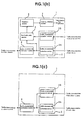
- FIGS. 1(a), 1(b) and 1(c) are explanatory views of a principle of the present invention.
- the transmission path controlling apparatus (the source communication apparatus 1S and the destination communication apparatus 1D) according to the present invention includes, as shown in FIG. 1(b), a traffic characteristic collection section 3, a traffic characteristic notification section 4, a load calculation section 5, a decision section 6 and a load equalization section 7.
- the traffic characteristic collection section 3 collects traffic characteristics of those of the transmission paths 2-i connected to the communication apparatus 1 or the other communication apparatus.
- the traffic characteristic collection section 3 includes a traffic characteristic collection section 3A for collecting traffic characteristics at the communication apparatus 1 itself, and a traffic characteristic reception section 3B for receiving traffic characteristics notified of from the other communication apparatus.
- the traffic characteristic notification section 4 notifies the other communication apparatus of the traffic characteristics collected by the traffic characteristic collection section 3 (particularly 3A).
- the load calculation section 5 calculates load based on the traffic characteristics collected by the traffic characteristic collection section 3.
- the decision section 6 discriminates whether or not a transmission path should be added or deleted based on the load information determined by the load calculation section 5, and the load equalization section 7 equalizes the load determined by the load calculation section 5 among the plurality of transmission paths.
- the transmission path controlling apparatus (the intermediate communication apparatus 1R) according to the present invention includes, as shown in FIG. 1(c), a traffic characteristic collection section 3 and a traffic characteristic notification section 4.
- the traffic characteristic collection section 3 collects traffic characteristics of those of the transmission paths 2-i connected to the communication apparatus 1 or the other communication apparatus.
- the traffic characteristic collection section 3 includes a traffic characteristic collection section 3A for collecting traffic characteristics at the communication apparatus 1 itself, and a traffic characteristic reception section 3B for receiving traffic characteristics notified of from the other communication apparatus.
- the traffic characteristic notification section 4 notifies the other communication apparatus of the traffic characteristics collected by the traffic characteristic collection section 3 (3A and 3B).
- the transmission path controlling apparatus which is provided in each of the source communication apparatus 1S, destination communication apparatus 1D and intermediate communication apparatus 1R, with such a traffic characteristic collection section 3, traffic characteristic notification section 4, load calculation section 5, decision section 6 and load equalization section 7 as described above
- the traffic characteristic collection section 3 may have means for smoothing the collected traffic characteristic values, or may have means for determining a maximum value of the collected traffic characteristic values as a representative value of the traffic characteristic values.
- the traffic characteristic notification section 4 may have means for notifying (providing) the information regarding the traffic characteristics making use of a packet provided by a routing protocol, or may have means for notifying the information regarding the traffic characteristics after each of a fixed period, or else may have means for notifying the information regarding the traffic characteristic with a message of the RSVP expanded.
- the traffic characteristic collection section 3 may have means for collecting a unit of a flux of flows for collecting traffic characteristics in a unit of a label which is used by a communication apparatus of the label switch type such as MPLS (Multi-Protocol Label Switching).
- MPLS Multi-Protocol Label Switching
- the traffic characteristic collection section 3 provided in the source communication apparatus 1S may have means for discriminating a utilization (a utilization rate) of each of the transmission paths 2-i connected to the source communication apparatus 1S based on an average utilization (an average utilization rate) of the transmission paths 2-i connected to the intermediate communication apparatus 1R collected from the intermediate communication apparatus 1R.
- the traffic characteristic collection section 3 provided in the source communication apparatus 1S may have means for discriminating a utilization of each of the transmission paths 2-i connected to the source communication apparatus 1S based on a maximum utilization of the transmission paths 2-i connected to the intermediate communication apparatus 1R collected from the intermediate communication apparatus 1R.
- the traffic characteristic collection section 3 provided in the source communication apparatus 1S may have means for discriminating after each fixed period whether or not each of the transmission paths 2-i is in congestion.
- the load calculation section 5 provided in the source communication apparatus 1S may have means for calculating effective load taking a number of abandoned packets generated in the intermediate communication apparatus 1R into consideration.
- an effective load calculation unit may be constructed so as to set an upper limit to the effective load when the effective load is to be calculated.
- the transmission path controlling apparatus may be constructed such that the load calculation section 5 provided in the source communication apparatus 1S has means for calculating effective load taking a number of abandoned packets generated in the intermediate communication apparatus 1R into consideration, and the decision section 6 provided in the source communication apparatus 1S has means for calculating an effective bandwidth from the effective load obtained by the effective load calculation unit and determining, regarding all of the transmission paths as one virtual pipe, a utilization of the virtual pipe.
- the transmission path controlling apparatus may be constructed such that the load calculation section 5 provided in the source communication apparatus 1S has means for calculating effective load taking a number of abandoned packets generated in the intermediate communication apparatus 1R into consideration, and the decision section 5 provided in the source communication apparatus 1S has a pipe utilization calculation unit for calculating an effective bandwidth from the effective load calculated by the effective load calculation unit and determining, regarding all of the transmission paths 2-i as one virtual pipe, a utilization of the virtual pipe, and comparing the pipe utilization obtained by the pipe utilization calculation unit with a set reference value and determining whether a transmission path is to be added or deleted in accordance with a result of the comparison.
- the decision section 6 provided in the source communication apparatus 1S may be constructed so as to add a transmission path when the pipe utilization obtained by the pipe utilization calculation unit is higher than a reference value for addition of a path, or may be constructed so as to delete a transmission path having a low load when the pipe utilization obtained by the pipe utilization calculation unit is lower than a reference value for deletion of a path.
- the load equalization section 7 provided in the source communication apparatus 1S may have a move effective bandwidth calculation unit for determining an effective bandwidth to be moved with each of the transmission paths 2-i from an average effective bandwidth calculated for all of the transmission paths 2-i based on an effective bandwidth obtained from effective load obtained taking a number of abandoned packets generated in the intermediate communication apparatus 1R into consideration.
- the load equalization section 7 provided in the source communication apparatus 1S may distribute packets flowing into the source communication apparatus 1S to the plurality of transmission paths in proportion to the effective bandwidths to be moved calculated by the move effective band calculation unit.
- the load equalization section 7 provided in the source communication apparatus 1S may be constructed so as to perform a calculation using a Hash function based on an address and distribute traffic flows at random based on a result of the calculation.
- a network which includes a source communication apparatus 1S, a destination communication apparatus 1D, a plurality of transmission paths 2-i capable of being set between the source communication apparatus 1S and the destination communication apparatus 1D, and an intermediate communication apparatus 1R interposed in any one of the transmission paths 2-i,
- a medium on which a transmission path controlling program for being used by one of the communication apparatus 1 which forms the network shown in FIG. 1(a) is recorded, the transmission path controlling program causing a computer to function as a traffic characteristic collection unit for collecting traffic characteristics of those of the transmission paths connected to the communication apparatus or the other communication apparatus, traffic characteristic notification unit for notifying the other communication apparatus of the traffic characteristics collected by the traffic characteristic collection unit, load calculation unit for calculating load based on the traffic characteristics collected by the traffic characteristic collection unit, decision section for deciding whether or not a transmission path should be added or deleted based on the load information determined by the load calculation unit, and a load equalization unit for equalizing the load determined by the load calculation unit among the plurality of transmission paths.
- the MPLS signifies a system which can simply and effectively perform a service which is difficult to realize with a router at present by using a label of the layer 2 in a specialized manner for an IP.
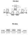
- FIGS. 2(a) and 2(b) show a network architecture and a manner of basic packet transfer of the MPLS.
- An MPLS network is composed of an edge label switching router (Edge Label Switching Router, hereinafter referred to as edge LSR) 11E and a core label switching router (Core Label Switching Router, hereinafter referred to as core LSR) 11C. This is called MPLS domain.
- edge LSR Edge Label Switching Router
- core LSR Core Label Switching Router
- the edge LSR 11E is a router which is positioned on the boundary with an existing internet network and adds a label to a packet to realize a network layer service of a high performance and a high added-value.
- This edge LSR terminates a LAN interface of an unlabeled frame base (Frame Base).
- the core LSR 11C is a router which exchanges a label of a labeled packet or cell.
- This core LSR 11C may be constructed so as to support not only label exchange but also layer 3 routing or layer 2 switching.
- LDP label distribution protocol
- reference characters 9S and 9D in FIG. 2(a) denote each a terminal such as a personal computer.
- a label coordinated with a path leading to a destination terminal is added to an IP packet arriving in the MPLS domain by an edge LSR 11E.
- a label A is provided to the IP packet, and the IP packet is transferred to a core LSR 11C.
- the core LSR 11C looks over only the label and switches the IP packet to an outgoing path corresponding to the label A.
- a label B is provided newly to the packet. This is called label swapping.
- label swapping In this manner, in the MPLS domain, while label swapping is performed successively, the IP packet is successively transferred toward a target destination terminal 9D in accordance with the label.
- the label is removed and transferred to the MPLS domain.
- the method according to 1 ⁇ wherein an existing switch is used is a method wherein an existing switch such as an asynchronous transfer mode (ATM) or a frame relay (represented also as FR), and in the ATM, a region of a virtual path identifier (VPI) and a virtual channel identifier (VCI) is used as a label, but in the frame relay, the DLCI is used as a label.
- ATM asynchronous transfer mode
- FR frame relay
- a region of a virtual path identifier (VPI) and a virtual channel identifier (VCI) is used as a label, but in the frame relay, the DLCI is used as a label.
- shim header In the method according to 2 ⁇ wherein a new label is defined, a newly defined label called "shim header" is used.
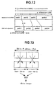
- the shim header is inserted between the layer 3 and the layer 2, and an outline of it is illustrated in FIG. 3.
- a TTL and a pointer S for a label stack are provided in addition to a label as shown in FIG. 3.
- labels for the ATM/FR also labels for the PPP over SONET and labels for the ether frame (LAN) are defined (refer to the PPP and the LAN shown on the right side in FIG. 3).
- a label has a length of, for example, 4 octets and is indicated as shown in FIG. 4.
- Such labels can have a hierarchical structure, and the structure is called "label stack".
- the label and other additional information illustrated in FIG. 4 is sometimes indicated in the MPLS header defined by the MPLS or indicated in the L2 header or the ATM header.
- the S (Bottom of Stack) indicated in FIG. 4 is set to 1 where the entry is the last entry positioned at the lowermost position of the label stack, and it is set to 0 for all of the other entries.
- the TTL Time-to-Live
- FIG. 4 represents a field used to encode a TTL and is decremented one by one before a labeled packet is forwarded.
- a packet whose TTL becomes zero as a result of the decrementing must not be forwarded any more, and in this instance, either the packet is abandoned as it is, or it is handed to processing of the network layer with the label stack removed therefrom. This packet must not be forwarded also after it is handed to the processing of the network layer.
- LSP label switched path
- the LSP signifies a path from an LSR at the entrance to another LSR at the exit, and may pass intermediate LSRs, an example can be seen also from FIG. 5.
- a label at each LSR is determined in a coordinated relationship with the LSP. While description is hereinafter given, in the present invention, collection of traffic characteristics is performed for each LSP.
- the LSP-tunnel is executed expanding the conventional RSVP, and the background of this system arises from that, where the MPLS incorporates the RSVP, a flow can be managed with increased flexibility by unifying them.
- the LSP-tunnel defines, for the RSVP, the following five new objects [LABEL REQUEST (used in a path message (PATH message)), LABEL (used in a Resv message), EXPLICIT ROUTE (used in a PATH message), RECORD ROUTE (used in a PATH message or a Resv message) and SESSION ATTRIBUTE (used in a PATH message)].
- LABEL REQUEST used in a path message (PATH message)
- LABEL used in a Resv message
- EXPLICIT ROUTE used in a PATH message
- RECORD ROUTE used in a PATH message or a Resv message
- SESSION ATTRIBUTE used in a PATH message
- the LABEL REQUEST object is used in a PATH message and is used to determine a label regarding the path by an intermediate router and a reception router.
- a source LSR produces a PATH message having a LABEL REQUEST, and further, a node which has transmitted the LABEL REQUEST must make preparations for reception of a Resv message corresponding to the PATH message. If a PATH message which does not include a LABEL REQUEST is received, then a LABEL REQUEST object must not be written into the PATH message.
- each node which receives the Resv message having the LABEL object uses the label as a label of the output side of the LSP-tunnel, and if the node is not the source of the LABEL REQUEST, then the node executes processing of allocating a new label and placing the new label into the LABEL object of the Resv message. Then, the label transmitted to the upstream is used as an input side label of the LSP-tunnel.
- EXPLICIT ROUTE object is used in a PATH message. If this object appears in a PATH message, then the PATH message must be transferred along a path explicitly indicated by the ERO.
- the ERO is intended to be used for explicit routing.
- the RECORD ROUTE object is used in a PATH message or a Resv message and allows a transmission node to receive information regarding an actual path of the LSP-tunnel. This is similar to a path vector (path vector) and can be used also for detection of a loop.
- a SESSION ATTRIBUTE object is used in a PATH message.
- This SESSION ATTRIBUTE object can be provided to a PATH message and used for identification and diagnosis of a session. Further, this object has pre-emission (preemption), priority, local protection and so forth.
- FIG. 6 illustrates a flow of a message of an LSP-tunnel in which the RSVP is used.
- the RSVP-tunnel is a Downstream-on-demand system since a label is allocated from the downstream.
- a first MPLS router (LSR1) in an MPLS domain places a LABEL REQUEST object into a PATH message of the RSVP and transmits the PATH message to the downstream. Thereafter, if the PATH message arrives at a node (LSR4) of the destination, then the destination node (LSR4) places a LABEL object into a Resv message and returns the Resv message to the upstream.
- LSR4 node
- the manner of allocation of a label is such as described hereinabove.
- a traffic characteristic value is embedded into and transferred together with the RSVP message.
- the LSP is set using a label of the MPLS.
- an LSP setting protocol such as the RSVP-LSP-Tunnel is used.
- reference character 11R denotes a repeating MPLS router (an intermediate communication apparatus).
- a portion of a transmission path between routers is called link, and, for example, a transmission path 12-1 in FIG. 7 is composed of M links (link_1 to link_M).
- N is a natural number
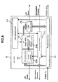
- FIG. 8 shows a functional block diagram of an exemplary embodiment of an MPLS router which forms an IP network.
- the MPLS router 11 includes an IP packet transfer section 111, a routing protocol section 112, a path selection section 113, an LSP selection section 114. an LSP setting section 115 and a traffic engineering section 116.
- the IP packet transfer section 111 has a function of performing desired processing such as IP packet transfer processing for an input packet and transferring the packet to another router.
- the routing protocol section 112 mediates notification of traffic characteristics to another router or collection of traffic characteristics from another router. It is to be noted that the routing protocol section 112 further has a function of rendering, when the MPLS router is connected to the network, the routing protocol operative to discover the other MPLS routers connected to the network. For the discovery, a Hello packet is used usually.
- the path selection section 113 has a function of producing a link state database (Link State Database) 113A for path selection when the topology of the network is discriminated by the routing protocol.
- the link state database 113A cooperates with the LSP setting section 115 through the LSP selection section 114 to set an LSP with another MPLS router.
- the LSP selection section 114 has a function of cooperating with the link state database 113A of the path selection section 113 to produce an alternate path information database 114A for LSP selection. At this time, a routing table unique to the MPLS which is not used in conventional routing protocols is produced.
- the alternate path information database 114A cooperates with the traffic engineering section 116 to set an alternative path using an LSP as needed. In short, a plurality of LSPs to an MPLS router at the end are set so that load may be balanced between the LSPs.
- the LSP setting section 115 has a function of setting a plurality of LSPs to an MPLS router at the end in response to a result of LSP selection by the LSP selection section 114.
- a result of the LSP setting by the LSP setting section 115 is transmitted to the IP packet transfer section 111, and a transfer form of an IP packet is set by the IP packet transfer section 111.
- the traffic engineering section 116 has a series of functions regarding a load balance according to the present invention. As shown in FIG. 9, the traffic engineering section 116 includes a load observation section 116A, a traffic characteristic value calculation section 116B, a traffic engineering calculation section 116C and a load adjustment section 116D.
- the load observation section 116A has a function of sending traffic characteristic values such as a utilization and a packet loss number sent thereto from the packet transfer section 111 to the traffic characteristic value calculation section 116B.
- the traffic characteristic value calculation section 116B has a function of performing smoothing or maximization of the traffic characteristic values and transmitting a resulting value to another MPLS router and another function of collecting traffic characteristic values sent thereto from another MPLS router and sending them to the traffic engineering calculation section 116C.
- the traffic engineering calculation section 116C has a function of performing calculation of an effective load, an effective bandwidth and so forth and performing adjustment of load in response to the bandwidths of the individual LSPs. A result of the calculation (operation) obtained by the traffic engineering calculation section 116C is transmitted to the load adjustment section 116D.
- the load adjustment section 116D has a function of determining a width of a traffic share based on the information from the traffic engineering calculation section 116C and sending a result of the determination to the LSP setting section 115 through the LSP selection section 114.
- the LSP setting section 115 thereafter sets a traffic share width at the IP packet transfer section 111.
- the traffic engineering section 116 has functions of a traffic characteristic collection section for collecting traffic characteristics of LSPs (transmission paths) connected to the LSP router itself or the other MPLS routers, a traffic characteristic notification section for notifying the other MPLS routers of the traffic characteristics collected by the traffic characteristic collection section, a load calculation section for calculating load based on the traffic characteristics collected by the traffic characteristic collection section, a decision section for deciding whether or not an LSP should be added or deleted based on the load information determined by the load calculation section, and a load equalization section for equalizing the load determined by the load calculation section among the plurality of LSPi (i is a natural number).
- This traffic engineering section 116 makes a principal part of the transmission path controlling apparatus of the present invention.
- the load observation section 116A and the traffic characteristic value calculation section 116B exhibit the function of the traffic characteristic collection section 3
- the traffic engineering section 116 exhibits the function of the traffic characteristic notification section 4
- the traffic engineering calculation section 116C exhibits the functions of the load calculation section 5, decision section 6 and load equalization section 7.
- the traffic characteristic collection unit has a function of collecting traffic characteristics of those of the transmission paths connected to the MPLS router or the other MPLS routers
- traffic characteristic notification unit for functioning as the traffic characteristic notification section
- the traffic characteristic notification unit has a function of notifying the other MPLS routers of the traffic characteristics collected by the traffic characteristic collection unit
- a load calculation unit for functioning as the load calculation section
- the load calculation unit has a function of calculating load based on the traffic characteristics collected by the traffic characteristic collection unit
- a discrimination unit for functioning as the decision section the discrimination unit has a function of discriminating whether or not a transmission path should be added or deleted based on the load information determined by the load calculation unit
- a load equalization unit for functioning as the load equalization section
- the installation may be performed by setting a recording medium such as a floppy disk or an MO disk to a computer or by using a transmission path controlling program distributed over a network (for example an IP network).
- a recording medium such as a floppy disk or an MO disk
- a transmission path controlling program distributed over a network (for example an IP network).
- any MPLS router can serve as a source MPLS router, a destination MPLS router or a repeating MPLS router, and consequently, although the present embodiment is shown as an example wherein the traffic engineering section 116 of each of the source MPLS router 11S, destination MPLS router 11D and repeating MPLS router 11R shown in FIG.
- the traffic engineering section of the source MPLS router 11S has the functions of the traffic characteristic collection section, traffic characteristic reception section, load calculation section, decision section and load equalization, and the traffic engineering section provided in each of the destination MPLS router 11D and repeating MPLS router 11R other than the source MPLS router 11S has only the functions of the traffic characteristic collection section and traffic characteristic notification section.
- the MPLS router 11 performs, for each port thereof, traffic collection regarding required traffic items [for example an output packet amount from an output port, an abandoned packet number (NLOSS) at the output port, a logical bandwidth (LBW) of the output port and so forth] as traffic characteristic values after each time tl [seconds (sec)] (procedure S1).
- required traffic items for example an output packet amount from an output port, an abandoned packet number (NLOSS) at the output port, a logical bandwidth (LBW) of the output port and so forth.
- the MPLS router 11 calculates a transmission line utilization CUTY at present from the obtained traffic characteristic values in accordance with the following expression (procedure 2).
- CUTY output packet amount from output port/logical bandwidth of output port
- the traffic characteristic collection section has means for calculating utilizations of the transmission paths connected to the router based on the collected traffic characteristic values. As a result, in what condition each of the transmission paths is used can be grasped in detail.
- the processing manner is such as follows.
- the traffic characteristic collection section has means for smoothing information (the transmission line utilization CUTY) regarding collected traffic characteristic values. More particularly, it is considered that the traffic characteristic collection section has means for smoothing, after traffic characteristics of transmission paths connected to the MPLS router are collected, the statistical values in accordance with, for example, the Exponential Moving Average method. As a result, an influence of a sudden traffic variation can be reduced.
- a smoothing unit may be constructed so as to smooth the utilizations calculated by the utilization calculating unit. Consequently, the utilizations of the individual transmission paths can be grasped accurately while eliminating traffic variation influences.
- the traffic characteristic collection section has means for determining a maximum value of collected characteristic values as a representative value of the traffic characteristic values.
- both of the smoothing processing and the maximum value selection processing may be performed or only one of the smoothing processing and the maximum value selection processing may be performed.
- a total number TLOSS of abandoned packets may be calculated in accordance with the following expression.
- TLOSS(n) TLOSS(n-1) + NLOSS
- TLOSS(n) is the total number of abandoned packets after updated
- TLOSS(n-1) is the total number of abandoned packets before updated
- NLOSS is the number of newly abandoned packets.
- the MPLS router 11 executes distribution of the track characteristic values (MUTY, TLOSS and so forth) after each time t2 [sec] making use of Flooding of the routing protocol.
- TLOSS is reset (that is, to 0) after completion of the flooding.
- MUTY is reset (that is, to 0).
- the traffic characteristic notification section has means for notifying information regarding traffic characteristics utilizing a packet prepared by the routing protocol. More particularly, it is considered that the traffic characteristic notification section has means for distributing, after traffic characteristics of the transmission paths connected to the MPLS router are collected, the characteristic values making use of a packet prepared by the routing protocol such as the OSPF or the IBGP to notify another MPLS router of the information.
- the routing protocol such as the OSPF or the IBGP
- the traffic characteristic notification section has means for notifying information regarding traffic characteristics after each fixed period t2 [sec].
- t2 the arithmetic load applied to an arithmetic unit such as a CPU which executes arithmetic operation and so forth can be reduced.
- the traffic characteristic notification section has means for notifying information regarding traffic characteristics with a message of the RSVP expanded. More particularly, it is considered that the traffic characteristic notification section has means for distributing, after traffic characteristics of the transmission paths connected to the MPLS router are collected, the characteristic values with a message of the RSVP expanded to notify another MPLS router of the information.
- an existing protocol can be utilized, and consequently, it is not necessary to newly prepare a routing protocol for exclusive use, which contributes to reduction of the cost and so forth.
- the traffic characteristic collection section has means for collecting a unit of a flux of flows for collection of traffic characteristics in a unit of a label used in the MPLS. As a result, collection of fine traffic characteristic becomes possible, which contributes to augmentation of the collection accuracy.
- a load distribution algorithm performed by a traffic engineering section 116' of each of the repeating MPLS routers 11R' and the destination router 11D'(the routers mentioned are hereinafter denoted generally by 11') having the construction just described is described in detail below.
- the traffic engineering section 116' of the MPLS router 11' performs, for each port thereof, traffic collection regarding required traffic items [for example an output packet amount (L) from an output port, an abandoned packet number (NLOSS) at the output port, a logical bandwidth (LBW) of the output port and so forth] as traffic characteristic values after each time tl [seconds (sec)].
- required traffic items for example an output packet amount (L) from an output port, an abandoned packet number (NLOSS) at the output port, a logical bandwidth (LBW) of the output port and so forth.
- the traffic engineering section 116' performs smoothing processing of the obtained output packet amounts.
- maximization extraction processing is performed. This processing is performed by placing a maximum value of the observation values as a work value ML. It is to be noted that the maximization extraction processing can be omitted.
- the traffic engineering section 116' calculates a total number TLOSS of abandoned packets in accordance with the expression (4).
- the traffic engineering section 116' executes distribution of the traffic characteristic values (ML, TLOSS and so forth) after each time t2 [sec] making use of Flooding of the routing protocol.
- the traffic engineering section 116' similarly to the traffic engineering section 116, the traffic engineering section 116' resets TLOSS (that is, to 0) after each completion of the flooding and, where the maximum value is adopted as ML, the traffic engineering section 116' resets ML (that is, to 0) as well.
- the MPLS router 11' of the present modification can achieve those effects provided by the smoothing processing, the maximum value extraction processing, the total abandoned packet number calculation processing and the traffic characteristic value notification processing. Further, since the smoothing processing of information regarding the traffic characteristics is assigned to the MPLS router 11S which serves as a start point of load distribution, the time required to work the traffic characteristics by the MPLS router 11' can be reduced from that by the MPLS router 11 described above and the MPLS router 11' can be simplified in construction, which contributes to reduction of the cost and so forth.
- flooding information of which the MPLS router 11S which is determined as a start point of load distribution is notified includes the average link utilization (or maximum value of observation values) MUTY (or average output packet amount ML), abandoned packet number TLOSS, output port logical bandwidth LBW and so forth as described hereinabove.
- the link utilization MUTY of each router is calculated using an output port logical bandwidth LBW and so forth received together. Whether the other intermediate routers have an average link utilization calculation function and issues a notification of the calculated average link utilization MUTY, the link utilization calculation function need not to be provided for the MPLS router 11S side.
- the MPLS router 11S which serves as the start point of load variation performs path state checking, calculation of an effective load and load adjustment.
- congestion state checking of the individual routes from the MPLS router (start point router) 11S to the MPLS router (end point router) 11D is performed in the following manner after each fixed period t3 [sec].
- the congestion state checking for each route discriminates, from utilizations of each path, collected from each of the repeating MPLS routers 11R of the path, based on an average utilization of the transmission paths (links) connected to the repeating MPLS router 11R [this congestion state checking manner is referred to as congestion state checking manner where utilizations of links j (link j) of a path i are averaged].
- the traffic characteristic collection section provided in the source MPLS router 11S has means for discriminating a utilization of each transmission path connected to the source MPLS router based on an average utilization of the transmission paths connected to repeating MPLS routers collected from the repeating MPLS routers. As a result, this can contribute to augmentation of the efficiency in use of the network.
- the congestion state checking for each route may be such congestion state checking that it discriminates, from utilizations of each path, collected from each of the repeating MPLS routers, based on a maximum utilization of the transmission paths (links) connected to the repeating MPLS router (this congestion state checking manner is referred to as congestion state checking manner where a maximum value of utilizations of all links of a path i is adopted).
- path i Max(MUTY(link j, path i)
- the traffic characteristic collection section provided in a source MPLS router has means for discriminating a utilization of each transmission path connected to the source MPLS router based on a maximum utilization of transmission paths connected to repeating MPLS routers collected from the repeating MPLS routers.
- transmission path selection control can be performed within a degree of certainty.
- TLOSS path i ⁇ TLOSS link j
- i above is the number of the path (LSP) and j is the link number.
- the traffic characteristic collection section provided in a source MPLS router has means for discriminating after each fixed period t3 [sec] whether or not each transmission path is in congestion.
- Calculation of the effective load (Effective load) ⁇ effective path i may be performed in the following manner.
- the effective load is defined as an effective utilization calculated from a utilization of a link and a packet loss number at the link.
- an actual load applied to the link should be measured.
- the inside of a router actually has a multi-stage switch construction and it is difficult to directly measure the load. Accordingly, in the present embodiment, a load is estimated using only a utilization of a link and a packet loss number, and the estimated load is referred to as effective load.
- the effective load is described with reference to FIG. 10.
- the load ⁇ path i and the effective load at the link are equal to each other.
- the load ⁇ path i is corrected with a predetermined function f(TLOSS path i) so that a rather high load may be obtained, and a resulting value is used as the effective load.
- an upper limit ⁇ ceiling is provided to the effective load. This can be represented in the following expression.
- f(TLOSS path i) is a function regarding TLOSS path i
- ⁇ ceiling is an upper limit load, that is, an upper limit value to the effective load ⁇ effective path i.
- the effective load calculation unit is constructed such that, when it calculates an effective load, it sets an upper limit to the effective load. Consequently, load estimation of an excessive amount can be avoided, and as a result, appropriate transmission path selection control can be performed.
- the load adjustment is performed in the following manner.
- the load adjustment is executed after each time t4 [sec], and if the effective load to each path (LSP) can be calculated in such a manner as described above, then a utilization at all paths (LSP) is determined subsequently.
- all paths are regarded as a single virtual pipe, and a load to the pipe is calculated.
- the decision section provided in a source MPLS router has means for calculating effective bandwidths from effective loads obtained by the effective load calculation unit and regarding all of the transmission paths as one virtual pipe and then determining a utilization of the virtual pipe.
- the utilization may be determined in accordance with the following expression.
- the utilization obtained from the expression (11) is compared with a set reference value ⁇ offer1 for path addition, and when the obtained value of the utilization is higher than the reference value for path addition, a new transmission path is added. Further, the utilization obtained from the expression (11) is compared with a set reference value for path deletion similarly, and if the obtained value of the utilization is lower than a reference value ⁇ offer2 for path deletion, then a path whose load is low is deleted. In particular, if the calculated load described above is high, then a new path is added, but if it is low, an existing path is deleted.
- the decision section provided in a source MPLS router has means for comparing a pipe utilization obtained by the pipe utilization calculation unit with a set reference value to perform discrimination of whether or not a transmission path should be added or deleted in response to a result of the comparison, and adds a new transmission path if the pipe utilization obtained by the pipe utilization calculation unit is higher than a reference value for path addition, but deletes a transmission path whose load is low if the pipe utilization obtained by the pipe utilization calculation unit is lower than a reference value for path deletion.
- up-to-date optimum path selection can be performed.
- a difference value ⁇ U(t) between two pipe utilizations obtained after a very small interval t4 is calculated as the rate of change of the pipe utilization per time in accordance with the following expression.
- ⁇ effective all(t) is the total utilization of all paths at time t
- ⁇ effective all(t-1) is the total utilization at a measurement time t-1 prior by one cycle to time t.
- the utilization obtained in accordance with the expression (11) and a reference value ⁇ offer1 for path addition set therefore are compared with each other, and the rate of change obtained in accordance with the expression (12) and a reference value ⁇ offerd1 for path addition set therefore are compared with each other.
- the utilization obtained in accordance with the expression (11) and a reference value ⁇ offer2 for path deletion set therefore are compared with each other, and the rate of change obtained in accordance with the expression (12) and a reference value ⁇ offerd2 for path deletion set therefore are compared with each other.
- logical ANDing (and) of results of comparison is used for discrimination of addition of a path
- logical ORing (or) of results of comparison is used for discrimination of deletion of a path
- the criteria for addition/deletion of a path are not limited to the combination given above, but those criteria (logical ANDing and logical ORing) may be used in a different combination in accordance with a configuration or a state of the network, or some other criteria may be used. This allows an integrated amount of the pipe utilization to be grasped appropriately in accordance with the configuration or the state of the network.
- an integral value ⁇ MU(t) of the pipe utilization within a fixed time t4 may be calculated in accordance with the following expression.
- ⁇ MU(t) is an integral value of the pipe utilization MU within the fixed time from t to t4.
- the utilization obtained in accordance with the expression (11) and a reference value ⁇ offer1 for path addition set therefore are compared with each other, and the integrated amount obtained in accordance with the expression (13) and a reference value ⁇ offeril for path addition set therefore are compared with each other.
- a new transmission path is added based on results of the comparison.
- the utilization obtained in accordance with the expression (11) and a reference value ⁇ offer2 for path deletion set therefore are compared with each other, and the integrated amount obtained in accordance with the expression (13) and a reference value ⁇ offeri2 for path deletion set therefore are compared with each other.
- a path which has a comparatively low load is deleted based on results of the comparison.
- various criteria such as logical ORing and logical ANDing of the results of comparison may be used in a suitable combination in accordance with the configuration or the state of the network, and this allows the integrated amount of the pipe utilization to be grasped appropriately. Further, where discrimination is performed based only on the integrated amount without using the utilization, decision of addition or deletion of a path can be performed with a simpler construction.
- the decision section provided in the source router has a calculation unit for calculating an effective bandwidth from the effective load obtained by the effective load calculation unit and for determining, regarding all of the transmission paths as one virtual pipe, information regarding a utilization of the virtual pipe (a pipe utilization, a rate of change of the pipe utilization, an integrated amount of the pipe utilization) and is constructed so as to perform decision of whether or not a transmission path should be added or deleted based on the information regarding the utilization of the virtual pipe (at least one of the pipe utilization, the rate of change of the pipe utilization, and the integrated amount of the pipe utilization). Consequently, it is possible to perform addition and deletion of a transmission path appropriately taking the loads of the transmission paths at present into consideration, and distribution of the load can be anticipated efficiently and selection of an appropriate path can be performed in accordance with the situation of the network or the performance of the hardware.
- the decision section provided in the source router is constructed so as to perform comparison of at least one of a set of the pipe utilization obtained by the calculation unit and a first reference value ( ⁇ offer1, ⁇ offer2), another set of the rate of change obtained by the calculation unit and a second reference value ( ⁇ offerd1, ⁇ offerd2) and a further set of the integrated value obtained by the calculation unit and a third reference value ( ⁇ offeri1, ⁇ offeri2), and perform decision of whether or not a transmission path should be added or deleted in response to a result of the comparison.
- a path of a candidate for deletion is selected based on several conditions, and the utilization of all paths (loads to the other transmission paths) when the path of the candidate for deletion is deleted is estimated and compared with a predetermined reference value. Then, a path to be deleted actually is determined based on a result of the comparison.
- deletion of multi-paths is performed in accordance with the following algorithm.
- the decision section provided in the source router includes means for selecting a candidate of a transmission path as an object of deletion based on the load information determined by the load calculation unit, and for estimating the load to the other transmission paths when the transmission path of the candidate of deletion selected by the deletion candidate selection unit is deleted, and for comparing the load of the other transmission paths estimated by the load estimation unit with a predetermined reference value and determining whether or not the transmission path of the candidate of deletion should be deleted in response to a result of the comparison.
- the path deletion algorithm described above is executed using the result of comparison as a trigger so that deletion of a path is performed actually.
- the decision section provided in the source router further includes a trigger unit for triggering the selection unit, estimation unit and determination unit to operate based on the information regarding the pipe utilization obtained by the calculation unit.
- a transmission path can be deleted in an up-to-date manner in response to a situation of the entire network.
- an effective bandwidth (EBW) to be moved is calculated.
- the effective bandwidth is calculated in accordance with an expression (14) to perform load distribution.
- effective bandwidth to be moved of ith path (average value of effective bandwidths of all paths - effective bandwidth of ith path) ⁇ logical bandwidth of ith path
- FIG. 11 a concept diagram for illustrating an effective bandwidth is illustrated in FIG. 11.
- ⁇ EBWi indicates an effective bandwidth to be moved, and this effective bandwidth is obtained by multiplying an effective load by the logical bandwidth LBW.
- ⁇ EBW can be calculated using an expression (15).
- ⁇ EBW path i ( ⁇ effective all - ⁇ effective path i ⁇ LBW path i
- the load equalization provided in a source MPLS router has move effective bandwidth calculation means for determining an effective bandwidth to be moved at each of transmission paths from an average effective bandwidth determined for all transmission paths based on effective bandwidths obtained from effective loads obtained taking numbers of abandoned packets generated in repeating MPLS routers into consideration. Consequently, equalization of load with bandwidths of transmission paths taken into consideration can be performed.
- IP packets flowing in are distributed to a plurality of paths in proportion to effective bandwidths to be moved calculated in accordance with the expression (14).
- calculation by a Hash function is performed based on IP addresses and the IP traffic flow is distributed at random based on a result of the calculation.
- the track share which has a significance of load adjustment is a parameter used to perform load distribution, and the sum total of traffic shares is a total value of actual traffic through all paths.
- the width of a traffic share is an integer from 0 to 65,535 where the CRC (cyclic redundancy check) 16 is used.
- the load adjustment apparatus can perform CRC calculation based on an IP address (host address, destination address) of the IP packet, and as a result, a certain value between 0 and 65,535 is allocated to the IP flow.
- the present load adjustment mechanism has a function of degrading an IP address to a width of a certain integer. In other words, IP flows arriving at a router are accommodated at random into individual paths.
- the load equalization section provided in a source MPLS router is constructed such that it has a unit for distributing packets flowing into the source MPLS router to a plurality of transmission paths in proportion to effective bandwidths to be moved determined by the move effective bandwidth calculation unit and further that it thereupon performs arithmetic operation using a Hash function based on addresses and distributes traffic flows at random based on a result of the arithmetic operation.
- traffic flows can be distributed precisely by simple calculation.
- a destination IP address of 32 bits included in an IP packet is first divided into four areas of 8 bits. Then, the values of two adjacent 8-bits are replaced alternately, and the upper 16 bits and the lower 16 bits are logically exclusively ORed. Finally, the value of 16 bits produced in this manner is converted into an integer, and the integer is used as a hash value (output value of the Hash function).
- the load equalization section provided in the source router is constructed so as to perform at least one of replacement of positions and logical operation for bit values of an input value as the calculation by the Hash function to produce a random integer value. This allows simplification of the hash calculation and also allows distribution of traffic flows to be performed at a high speed.
- a control value for example, a protocol ID, a port number or the like
- the load equalization section provided in the source router is constructed so as to additionally use, as an input value for the Hash function, a control value other than the address included in each packet. This increases the disturbance degree of the output value by the hash calculation and allows efficient and effective distribution of traffic flows.
- Adjustment of the traffic share is performed based on the calculation result.
- Adjustment of the traffic share is performed based on the calculation result.
- the routing protocol operates and performs discovery of the other MPLS routers connected to the network. For such discovery, usually a hello packet is used. If the topology of the network is cleared up by the routing protocol, then a link state database 113A is produced by the path selection section 113. LSPs are set between the MPLS router 11 and the other MPLS routers by the LSP setting section 115 through the LSP selection section 114 using the link state database 113A. Further, the LSP selection section 114 cooperates with the link state database 113A of the path selection section 113 to produce an alternate path information database 114A and thus produces a routing table unique to the MPLS and not used by any other conventional routing protocol.
- the alternate path information database 114A cooperates with the traffic engineering section 116 to set an alternative path using the LSPs as needed. In short, by setting a plurality of LSPs between the MPLS router 11 and an MPLS router at the end point, balancing of load can be performed between the LSPs.
- the series of functions regarding balancing of load are functions of the traffic engineering section 116
- track characteristic values such as a utilization and a packet loss number are sent from the IP packet transfer section 111.
- the load observation section 116A sends the values to the traffic characteristic value calculation section 116B.
- the traffic characteristic value calculation section 116B performs smoothing or maximization of the traffic characteristic values and transmits a resulting value to the other MPLS routers.
- traffic characteristic values sent to the MPLS router 11 from the other MPLS routers are collected by the traffic characteristic value calculation section 116B and sent to the traffic engineering calculation section 116C.
- the traffic engineering calculation section 116C performs calculation of effective loads and effective bandwidths and performs load adjustment in accordance with the bandwidths of the individual LSPs.
- a result of the load adjustment is transmitted to the load adjustment section 116D, by which a width of the track share is determined. Then, a result of the determination is set by the IP packet transfer section 111 through the LSP setting section 115.
- each of the routers 11R and 11D other than the source MPLS router 11S collects traffic characteristics of transmission paths connected to the other routers and notifies the source router of the collected track characteristics.
- the source MPLS router 11S collects traffic characteristics of transmission paths connected to the source router and calculates effective loads based on one or both of the thus collected traffic characteristics and traffic characteristics obtained from the other routers. Then, based on the effective load information, the source MPLS router 11S performs discrimination of whether or not a transmission path should be added or deleted and further performs equalization of the obtained effective load between a plurality of transmission paths.
- each router has a traffic characteristic observation function and a traffic characteristic value notification function, and a router (source router) which serves as a start point of load distribution can dynamically perform bandwidth management of a plurality of paths to another router (destination router) which serves as an end point.
- load distribution in accordance with free bandwidths can be performed.
- a plurality of routes (transmission paths) can be set from a router (source router) which serves as a start point to another router (destination router) which serves as an end point from among routers in an IP network and distribution of load can be performed among the set routes, traffic engineering can be achieved within the network such as the Internet irrespective of the network topology and without depending upon the type of the transmission paths.
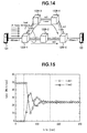
- LSR 120R-1 to 120R-5 denote each an LSR which includes the load distribution apparatus of the present invention, and a load generating apparatus 121 is connected to the LSR 120R-1 which serves as a source LSR while a load receiving apparatus 122 is connected to the LSR 120R-5 which serves as a load destination LSR.
- a plurality of links link1 to link5 are laid between the LSRs 120R-1 to 120R-5 such that they form a plurality of transmission paths 123-1 and 123-2.
- the network construction for experiment shown in FIG. 14 can be considered as an example of the network construction of the MPLS shown in FIG. 7.
- the link utilization (indicated by a void circle in the graph) of the link link1 was a little lower than 50 Mbit/sec and higher than 30 Mbit/sec of the congestion discrimination threshold value, and congestion occurred.
- the link utilization (a void triangle) of the link link3 was almost 0 Mbit/sec, and it can be seen that one-sidedness of the load appeared between the two links link1 and link3.
- the load distribution by the load distribution apparatus of the present invention was started at 40 seconds after the experiment was started.
- the link utilization of the link link1 decreased suddenly while the link utilization of the link link3 increased suddenly, and it can be seen that the load was distributed between the two links link1 and link3.
- the traffics of the two links link1 and link3 were turned and an over-controlled state was entered once.
- the difference became very small and the difference between the traffics of the two links link1 and link3 gradually converged.
- the convergence time of the traffics was 120 seconds after the load distribution was started.
- the Hash granularity is set rather high, then although the traffics are rendered unstable through over-control, load distribution can be achieved in a short time. In contrast, if the Hash granularity is set rather low, then although the time required for load distribution becomes long, load distribution can be achieved in a stable state while preventing the traffics from being rendered unstable through over-control. In other words, appropriate setting of the Hash granularity in accordance with the state of the network or the performance of the hardware allows efficient load distribution.
- a router is used as an example of the communication apparatus in the embodiment described above, the present invention is not only applied to a router but is widely applicable to other kinds of communication apparatus such as a gateway.
- each communication apparatus has a traffic characteristic observation function and a traffic characteristic value notification function, and a communication apparatus (source communication apparatus) which serves as a start point of load distribution can dynamically perform bandwidth management of a plurality of paths to another communication apparatus (destination communication apparatus) which serves as an end point. As a result, load distribution in accordance with free bandwidths can be performed.
- a plurality of routes can be set from a communication apparatus (source communication apparatus) which serves as a start point to another communication apparatus (destination communication apparatus) which serves as an end point from among communication apparatus in an IP network and distribution of load can be performed among the set routes, traffic engineering can be achieved within the network such as the Internet irrespective of the network topology and without depending upon the type of the transmission paths.
- the traffic characteristic collection section may smooth information regarding the collected traffic characteristic values, and this can reduce an influence of a sudden traffic variation.
- the traffic characteristic collection section may determine utilizations of the transmission paths connected to the communication apparatus based on the collected traffic characteristic values. This allows the utilizations of the transmission paths to be grasped particularly. In this instance, where a smoothing unit is constructed so as to smooth the utilizations determined by a utilization discriminating unit, the utilizations of the transmission paths can be grasped accurately while eliminating an influence of the traffic variation. Also where the traffic characteristic collection section has determines utilizations of the transmission paths connected to the communication apparatus based on the traffic characteristic values smoothed by the smoothing unit, a similar effect can be achieved.
- transmission path selection control can be performed with a degree of certainty.
- the traffic characteristic notification section may notify (provide) information regarding the traffic characteristics making use of a packet provided by a routing protocol, and according to this construction, an existing protocol can be utilized, and consequently, it is not necessary to newly prepare a routing protocol for exclusive use, which contributes to reduction of the cost and so forth.
- the traffic characteristic notification section may notify information regarding the traffic characteristics after each fixed period, and according to this construction, arithmetic load applied to an arithmetic unit such as a CPU which executes arithmetic operation and so forth can be reduced.
- the traffic characteristic notification section may notify information regarding the traffic characteristic with a message of the RSVP expanded, and according to this construct, an existing protocol can be utilized. Consequently, it is not necessary to newly prepare a routing protocol for exclusive use, which contributes to reduction of the cost and so forth.
- the traffic characteristic collection section may collect a unit of a flux of flows for collecting traffic characteristics in a unit of a label which is used by a communication apparatus of the label switch type, and according this construction, traffic characteristics can be collected finely, which contributes to augmentation of the collection accuracy.
- the traffic characteristic collection section provided in the source communication apparatus may determine a utilization of each of the transmission paths based on an average utilization of the transmission paths, and this can contribute to augmentation of the efficiency in use of the network.
- the traffic characteristic collection section provided in the source communication apparatus may determine a utilization of each of the transmission paths based on a maximum utilization of the transmission paths, and according to this construction, transmission path selection control can be performed with certainty.
- the traffic characteristic collection section provided in the source communication apparatus may determine after each fixed period whether or not each of the transmission paths is congested, and according to this construction, arithmetic load applied to an arithmetic unit such as a CPU which executes arithmetic operation and so forth can be reduced.
- the load calculation section provided in the source communication apparatus may calculate effective load taking a number of abandoned packets generated in the intermediate communication apparatus into consideration, and according to this construction, even if a load is not directly measured, an effective load can be estimated by a simple method. In this instance, an upper limit to the effective load can be set, and according to this construction, load estimation of an excessive amount can be avoided, and as a result, appropriate transmission path selection control can be performed.
- the decision section provided in the source communication apparatus may calculate an effective bandwidth from the effective load obtained by an effective load calculation unit and determining, regarding all of the transmission paths as one virtual pipe, a utilization of the virtual pipe, and according to this construction, it can be prevented to unnecessarily add a new transmission path and this can contribute also to effective utilization of the network.
- the transmission path controlling apparatus may be constructed so as to determine whether a transmission path is to be added or deleted based on the information regarding the pipe utilization obtained by the calculation unit. This allows addition and deletion of a transmission path appropriately with the loads to the transmission paths at present taken into consideration, and distribution of the load can be achieved efficiently.
- an transmission path addition-deletion discrimination unit may be constructed so as to perform discrimination of whether or not a transmission path should be added or deleted based on at least one of the pipe utilization, rate of change and integrated amount obtained by the calculation means, an appropriate path can be selected in accordance with the situation of the network or the performance of the hardware.
- the decision section can be constructed so as to compare the pipe utilization, rate of change and integrated value obtained by the calculation unit with respective reference values and perform determination of whether or not a transmission path should be added or deleted in response to a result of the comparison, and according to this construction, up-to-date optimum path selection can be performed.
- the calculation unit may be constructed so as to calculate a difference value between pipe utilizations and/or a differential value of the pipe utilization as the rate of change of the pipe utilization or may be constructed so as to determine a number of times by which the pipe utilization exceeds a reference value or an integral value of the pipe utilization as the integrated amount of the pipe utilization. This allows the calculation amount to be changed in accordance with the situation of the network or the performance of the hardware and allows efficient path selection.
- the decision section may selecting a candidate of a transmission path as an object of deletion based on the load information determined by the load calculation section, estimating the load to the other transmission paths when the transmission path of the selected candidate of deletion selected is deleted, and comparing the estimated load to the other transmission paths with a predetermined reference value and determining whether or not the transmission path of the candidate of deletion should be deleted in response to a result of the comparison.
- This allows appropriate selection of a transmission path to be deleted taking an influence when any transmission path is deleted into consideration. In this instance, where the information regarding the pipe utilization obtained by the calculation unit is used as a trigger for the operation, a transmission path can be deleted efficiently in response to the situation of the entire network.
- the load equalization section provided in the source communication apparatus may have a move effective bandwidth calculation unit for determining an effective bandwidth to be moved with each of the transmission paths from an average effective bandwidth calculated for all of the transmission paths based on an effective bandwidth obtained from effective load obtained taking a number of abandoned packets generated in the intermediate communication apparatus into consideration, and according to this construction, equalization of load with bandwidths of transmission paths taken into consideration can be performed.
- the load equalization section provided in the source communication apparatus may distribute packets flowing into the source communication apparatus to the plurality of transmission paths in proportion to the effective bandwidths to be moved calculated by the move effective band calculation unit, and according to this construction, precise equalization of load can be performed.
- the load equalization section provided in the source communication apparatus may be constructed so as to perform a calculation using a Hash function based on an address and distribute traffic flows at random based on a result of the calculation, and according to this construction, traffic flows can be distributed precisely by simple calculation.
- the load equalization section may be constructed so as to perform the calculation using a CRC (cyclic redundancy check) as the Hash function or perform calculation to produce a random integer value by replacement of bit positions of an input value as the Hash function or the load equalization section may be constructed so as to additionally use a control value other than the address included in each packet as an input value for the Hash function. This allows efficient and effective distribution of traffic flows to be performed.
- CRC cyclic redundancy check
Applications Claiming Priority (4)
| Application Number | Priority Date | Filing Date | Title |
|---|---|---|---|
| JP2000056254 | 2000-03-01 | ||
| JP2000056254 | 2000-03-01 | ||
| JP2000376615A JP4150159B2 (ja) | 2000-03-01 | 2000-12-11 | 伝送経路制御装置及び伝送経路制御方法並びに伝送経路制御プログラムを記録した媒体 |
| JP2000376615 | 2000-12-11 |
Publications (3)
| Publication Number | Publication Date |
|---|---|
| EP1130849A2 true EP1130849A2 (fr) | 2001-09-05 |
| EP1130849A3 EP1130849A3 (fr) | 2004-09-15 |
| EP1130849B1 EP1130849B1 (fr) | 2012-04-25 |
Family
ID=26586547
Family Applications (1)
| Application Number | Title | Priority Date | Filing Date |
|---|---|---|---|
| EP01104498A Expired - Lifetime EP1130849B1 (fr) | 2000-03-01 | 2001-03-01 | Appareillage de contrôle, méthode et programme de voie de transmission |
Country Status (3)
| Country | Link |
|---|---|
| US (1) | US7136357B2 (fr) |
| EP (1) | EP1130849B1 (fr) |
| JP (1) | JP4150159B2 (fr) |
Cited By (13)
| Publication number | Priority date | Publication date | Assignee | Title |
|---|---|---|---|---|
| GB2371704A (en) * | 2000-11-01 | 2002-07-31 | Parc Technologies Ltd | Calculating traffic flow between specific network nodes from measurements of total traffic flow in computer network links |
| EP1309148A2 (fr) * | 2001-10-30 | 2003-05-07 | Fujitsu Limited | Dispositif pour transférer des données |
| WO2004002109A1 (fr) * | 2002-06-24 | 2003-12-31 | International Business Machines Corporation | Equilibrage des charges dans des reseaux de donnees |
| FR2846170A1 (fr) * | 2002-10-18 | 2004-04-23 | Overnetworks | Procede d'optimisation du trafic sur internet. |
| EP1443722A2 (fr) | 2003-01-31 | 2004-08-04 | Fujitsu Limited | Dispositif de commande de largeur de bande de transmission |
| WO2004093393A1 (fr) | 2003-04-11 | 2004-10-28 | Fujitsu Limited | Systeme de communication mobile et procede de distribution de donnees du systeme |
| WO2005071901A1 (fr) * | 2003-12-26 | 2005-08-04 | France Telecom | Procede de mise a jour d'une table d'informations de routage et routeur correspondant |
| WO2005071900A1 (fr) * | 2004-01-23 | 2005-08-04 | Siemens Aktiengesellschaft | Optimisation de la repartition du trafic pour un routage multichemin |
| CN1309222C (zh) * | 2003-05-01 | 2007-04-04 | 株式会社Ntt都科摩 | 通信量分布控制装置和方法 |
| WO2007051960A1 (fr) | 2005-11-01 | 2007-05-10 | Nortel Networks Limited | Agregation de liaisons pour trafic encapsule |
| WO2009111959A1 (fr) * | 2008-03-13 | 2009-09-17 | 华为技术有限公司 | Procédé et dispositif de programmation et de répartition d'itinéraire |
| US7680046B2 (en) | 2002-07-11 | 2010-03-16 | Fujitsu Limited | Wide area load sharing control system |
| US8325618B2 (en) | 2006-07-05 | 2012-12-04 | Synopsys, Inc. | Electronic device, system on chip and method for monitoring a data flow |
Families Citing this family (120)
| Publication number | Priority date | Publication date | Assignee | Title |
|---|---|---|---|---|
| US7230924B2 (en) * | 2001-03-28 | 2007-06-12 | At&T Corp. | Method and apparatus for communications traffic engineering |
| AU2002304386A1 (en) * | 2001-06-27 | 2003-03-03 | Nokia Corporation | Method and system for efficient management and transport of traffic over a network |
| US7856599B2 (en) * | 2001-12-19 | 2010-12-21 | Alcatel-Lucent Canada Inc. | Method and system for IP link management |
| US8040869B2 (en) * | 2001-12-19 | 2011-10-18 | Alcatel Lucent | Method and apparatus for automatic discovery of logical links between network devices |
| US7515546B2 (en) * | 2001-12-19 | 2009-04-07 | Alcatel-Lucent Canada Inc. | Method and apparatus for automatic discovery of network devices with data forwarding capabilities |
| US7499410B2 (en) | 2001-12-26 | 2009-03-03 | Cisco Technology, Inc. | Fibre channel switch that enables end devices in different fabrics to communicate with one another while retaining their unique fibre channel domain—IDs |
| US20040136371A1 (en) * | 2002-01-04 | 2004-07-15 | Muralidhar Rajeev D. | Distributed implementation of control protocols in routers and switches |
| CA2415184C (fr) * | 2002-01-15 | 2009-06-30 | Nippon Telegraph And Telephone Corporation | Noeud, reseau de commutation de paquets, methode de commutation de paquets et programme |
| CA2416659C (fr) | 2002-01-22 | 2007-01-16 | Nippon Telegraph And Telephone Corporation | Appareil de liaison a capacite variable et procede permettant de regler la liaison variable |
| CA2418384A1 (fr) * | 2002-02-06 | 2003-08-06 | Nippon Telegraph And Telephone Corporation | Reseau optique, appareil d'interconnexion optique, reseau ip photonique et noeud |
| CA2419477C (fr) * | 2002-02-28 | 2010-05-04 | Nippon Telegraph And Telephone Corporation | Noeud utilise dans un reseau photonique, et reseau photonique |
| JP2003256310A (ja) * | 2002-03-05 | 2003-09-12 | Nec Corp | サーバ負荷分散システム、サーバ負荷分散装置、コンテンツ管理装置、及びサーバ負荷分散プログラム |
| JP3898535B2 (ja) * | 2002-03-14 | 2007-03-28 | 株式会社日立製作所 | データ転送装置 |
| US7616637B1 (en) | 2002-04-01 | 2009-11-10 | Cisco Technology, Inc. | Label switching in fibre channel networks |
| US7477657B1 (en) * | 2002-05-08 | 2009-01-13 | Juniper Networks, Inc. | Aggregating end-to-end QoS signaled packet flows through label switched paths |
| US7280472B2 (en) * | 2002-06-04 | 2007-10-09 | Lucent Technologies Inc. | Protection switching at a network node |
| US7206288B2 (en) | 2002-06-12 | 2007-04-17 | Cisco Technology, Inc. | Methods and apparatus for characterizing a route in fibre channel fabric |
| JP3923863B2 (ja) * | 2002-07-09 | 2007-06-06 | 株式会社日立製作所 | リクエストルータ装置 |
| JP2004140776A (ja) * | 2002-07-12 | 2004-05-13 | Nec Corp | ネットワークにおけるフレーム転送方法及びノード、フレーム転送プログラム |
| JP3521904B2 (ja) * | 2002-08-22 | 2004-04-26 | 日本電気株式会社 | イーサネット(r)におけるフレーム転送方法及びノード |
| CN100459534C (zh) * | 2002-10-07 | 2009-02-04 | 日本电信电话株式会社 | 分层网络节点及通过该节点构成的网络、节点和分层网络 |
| US7433326B2 (en) | 2002-11-27 | 2008-10-07 | Cisco Technology, Inc. | Methods and devices for exchanging peer parameters between network devices |
| CN1310473C (zh) * | 2003-01-07 | 2007-04-11 | 华为技术有限公司 | 基于同步数字传送网的数据传送方法 |
| JPWO2004073269A1 (ja) * | 2003-02-13 | 2006-06-01 | 富士通株式会社 | 伝送システム,配信経路制御装置,負荷情報収集装置および配信経路制御方法 |
| US20050195834A1 (en) * | 2003-03-31 | 2005-09-08 | Shunsuke Kikuchi | Load distribution system |
| JPWO2004088940A1 (ja) * | 2003-03-31 | 2006-07-06 | 富士通株式会社 | 負荷分散システム |
| US8428117B2 (en) | 2003-04-24 | 2013-04-23 | Fujitsu Semiconductor Limited | Image encoder and image encoding method |
| US7872976B2 (en) * | 2003-05-02 | 2011-01-18 | Alcatel-Lucent Usa Inc. | System and method for multi-protocol label switching network tuning |
| DE10325017A1 (de) * | 2003-06-03 | 2005-01-20 | Siemens Ag | Statistisches Verfahren für eine Verkehrsverteilung entsprechend Verkehrs-Verteilgewichten in einem paketorientierten Netz mit Mehrwegerouting |
| US20050008014A1 (en) * | 2003-07-07 | 2005-01-13 | Debasis Mitra | Techniques for network traffic engineering |
| US8085765B2 (en) * | 2003-11-03 | 2011-12-27 | Intel Corporation | Distributed exterior gateway protocol |
| DE102004007977A1 (de) * | 2004-02-18 | 2005-06-02 | Siemens Ag | Kommunikationssystem und Verfahren zum Optimieren der Auslastung eines Kommunikationssystems mit einer Vielzahl von Netzkoppelelementen |
| US8407365B2 (en) * | 2004-05-24 | 2013-03-26 | Tellabs Operations, Inc. | Method and system for autodiscovery of a network path |
| JP4390649B2 (ja) * | 2004-07-14 | 2009-12-24 | 富士通株式会社 | ネットワークループ検知装置 |
| US7916628B2 (en) | 2004-11-01 | 2011-03-29 | Cisco Technology, Inc. | Trunking for fabric ports in fibre channel switches and attached devices |
| US7496105B2 (en) * | 2004-11-05 | 2009-02-24 | Cisco Technology, Inc. | System and method for retrieving computed paths from a path computation element using encrypted objects |
| US7558276B2 (en) * | 2004-11-05 | 2009-07-07 | Cisco Technology, Inc. | System and method for retrieving computed paths from a path computation element using a path key |
| US7649844B2 (en) | 2004-12-29 | 2010-01-19 | Cisco Technology, Inc. | In-order fibre channel packet delivery |
| US8804653B2 (en) * | 2005-01-13 | 2014-08-12 | Telefonaktiebolaget Lm Ericsson (Publ) | System and method for call handoff between circuit switched and packet data wireless networks |
| US9306831B2 (en) * | 2005-02-14 | 2016-04-05 | Cisco Technology, Inc. | Technique for efficient load balancing of TE-LSPs |
| US20060256752A1 (en) * | 2005-05-10 | 2006-11-16 | Telefonaktiebolaget Lm Ericsson (Publ) | System and method for call handoff from packet data wireless network to circuit switched wireless network |
| US9654383B2 (en) | 2005-08-17 | 2017-05-16 | Avaya Inc. | Route optimization using measured congestion |
| US8369220B1 (en) | 2005-08-17 | 2013-02-05 | Avaya Inc. | Routing a flow of elastic traffic |
| US8719255B1 (en) * | 2005-08-23 | 2014-05-06 | Amazon Technologies, Inc. | Method and system for determining interest levels of online content based on rates of change of content access |
| JP4606333B2 (ja) * | 2005-09-20 | 2011-01-05 | 富士通株式会社 | ルーティング制御方法 |
| US7590123B2 (en) * | 2005-11-22 | 2009-09-15 | Cisco Technology, Inc. | Method of providing an encrypted multipoint VPN service |
| US7630372B1 (en) | 2005-12-30 | 2009-12-08 | At&T Corp. | Method and apparatus for providing access and egress uniform resource identifiers for routing |
| JP4616785B2 (ja) | 2006-03-28 | 2011-01-19 | 富士通株式会社 | サービス品質管理装置及びサービス品質管理方法 |
| US9542642B2 (en) | 2006-04-06 | 2017-01-10 | Samuel F. Wood | Packet data neural network system and method |
| US7796511B2 (en) * | 2006-04-06 | 2010-09-14 | Wood Samuel F | Self-routed layer 4 packet network system and method |
| JP5179031B2 (ja) * | 2006-09-13 | 2013-04-10 | 株式会社日立製作所 | 空きポートを有効に活用したストレージシステム |
| JP4677978B2 (ja) * | 2006-12-15 | 2011-04-27 | Kddi株式会社 | ネットワーク管理装置及びプログラム |
| JP5071165B2 (ja) | 2007-03-19 | 2012-11-14 | 日本電気株式会社 | 経路多重化通信システム、通信ノード及び通信方法 |
| US8065429B2 (en) * | 2007-06-28 | 2011-11-22 | Nokia Corporation | System, apparatus and method for associating an anticipated success indication with data delivery |
| US20090086633A1 (en) * | 2007-10-02 | 2009-04-02 | Chenjiang Hu | Using A Link-State Advertisement To Inform Nodes Of The Availability Of Traffic Management Resources |
| US20090287120A1 (en) | 2007-12-18 | 2009-11-19 | Searete Llc, A Limited Liability Corporation Of The State Of Delaware | Circulatory monitoring systems and methods |
| US9717896B2 (en) | 2007-12-18 | 2017-08-01 | Gearbox, Llc | Treatment indications informed by a priori implant information |
| US8636670B2 (en) | 2008-05-13 | 2014-01-28 | The Invention Science Fund I, Llc | Circulatory monitoring systems and methods |
| JP5304008B2 (ja) * | 2008-04-23 | 2013-10-02 | 日本電気株式会社 | 通信システム |
| JP5111236B2 (ja) * | 2008-05-22 | 2013-01-09 | 株式会社日立製作所 | データ転送システム |
| JP4957660B2 (ja) * | 2008-06-20 | 2012-06-20 | 富士通株式会社 | ラベルスイッチングネットワークにおける通信装置 |
| JP5239783B2 (ja) * | 2008-11-27 | 2013-07-17 | 富士通株式会社 | 経路計算方法及びノード装置 |
| US7983163B2 (en) * | 2008-12-11 | 2011-07-19 | International Business Machines Corporation | System and method for implementing adaptive load sharing to balance network traffic |
| JP5223717B2 (ja) * | 2009-02-16 | 2013-06-26 | 富士通株式会社 | 経路計算装置及び経路計算方法 |
| US20110063986A1 (en) | 2009-09-14 | 2011-03-17 | International Business Machines Corporation | System and method for load balancing traffic in a mpls network |
| US9185024B2 (en) * | 2010-03-08 | 2015-11-10 | The Chinese University Of Hong Kong | Path selection in streaming video over multi-overlay application layer multicast |
| JP5561006B2 (ja) * | 2010-08-05 | 2014-07-30 | 富士通株式会社 | データ転送装置、データ受信装置、データ転送方法、およびデータ転送プログラム |
| US8553562B2 (en) * | 2010-09-08 | 2013-10-08 | Telefonaktiebolaget L M Ericsson (Publ) | Automated traffic engineering for multi-protocol label switching (MPLS) with link utilization as feedback into the tie-breaking mechanism |
| US8553584B2 (en) * | 2010-09-08 | 2013-10-08 | Telefonaktiebolaget L M Ericsson (Publ) | Automated traffic engineering for 802.1AQ based upon the use of link utilization as feedback into the tie breaking mechanism |
| JP5621576B2 (ja) * | 2010-12-20 | 2014-11-12 | 日本電気株式会社 | パケット中継装置 |
| KR101309582B1 (ko) | 2011-09-05 | 2013-09-17 | 에스케이텔레콤 주식회사 | 멀티 네트워크에서의 로드 밸런싱을 위한 사용자 단말 및 그 방법 |
| US9608899B2 (en) * | 2011-11-21 | 2017-03-28 | Qualcomm Incorporated | Packet-based aggregation of data streams across disparate networking interfaces |
| JP5974665B2 (ja) * | 2012-06-22 | 2016-08-23 | 富士通株式会社 | 情報処理システム、中継装置、情報処理装置および情報処理方法 |
| US10261938B1 (en) | 2012-08-31 | 2019-04-16 | Amazon Technologies, Inc. | Content preloading using predictive models |
| US9369371B2 (en) | 2012-10-05 | 2016-06-14 | Cisco Technologies, Inc. | Method and system for path monitoring using segment routing |
| US9049233B2 (en) | 2012-10-05 | 2015-06-02 | Cisco Technology, Inc. | MPLS segment-routing |
| JP5969352B2 (ja) * | 2012-10-23 | 2016-08-17 | 日本電信電話株式会社 | 信号処理システム |
| US9094337B2 (en) * | 2012-12-21 | 2015-07-28 | Cieno Corporation | Source identification preservation in multiprotocol label switching networks |
| US10447575B1 (en) | 2012-12-27 | 2019-10-15 | Sitting Man, Llc | Routing methods, systems, and computer program products |
| US10397100B1 (en) | 2012-12-27 | 2019-08-27 | Sitting Man, Llc | Routing methods, systems, and computer program products using a region scoped outside-scope identifier |
| US10587505B1 (en) | 2012-12-27 | 2020-03-10 | Sitting Man, Llc | Routing methods, systems, and computer program products |
| US10476787B1 (en) | 2012-12-27 | 2019-11-12 | Sitting Man, Llc | Routing methods, systems, and computer program products |
| US10374938B1 (en) | 2012-12-27 | 2019-08-06 | Sitting Man, Llc | Routing methods, systems, and computer program products |
| US10404582B1 (en) | 2012-12-27 | 2019-09-03 | Sitting Man, Llc | Routing methods, systems, and computer program products using an outside-scope indentifier |
| US10411998B1 (en) | 2012-12-27 | 2019-09-10 | Sitting Man, Llc | Node scope-specific outside-scope identifier-equipped routing methods, systems, and computer program products |
| US10419335B1 (en) | 2012-12-27 | 2019-09-17 | Sitting Man, Llc | Region scope-specific outside-scope indentifier-equipped routing methods, systems, and computer program products |
| US10419334B1 (en) | 2012-12-27 | 2019-09-17 | Sitting Man, Llc | Internet protocol routing methods, systems, and computer program products |
| US10404583B1 (en) | 2012-12-27 | 2019-09-03 | Sitting Man, Llc | Routing methods, systems, and computer program products using multiple outside-scope identifiers |
| US10411997B1 (en) | 2012-12-27 | 2019-09-10 | Sitting Man, Llc | Routing methods, systems, and computer program products for using a region scoped node identifier |
| US10397101B1 (en) | 2012-12-27 | 2019-08-27 | Sitting Man, Llc | Routing methods, systems, and computer program products for mapping identifiers |
| US10212076B1 (en) | 2012-12-27 | 2019-02-19 | Sitting Man, Llc | Routing methods, systems, and computer program products for mapping a node-scope specific identifier |
| US10904144B2 (en) | 2012-12-27 | 2021-01-26 | Sitting Man, Llc | Methods, systems, and computer program products for associating a name with a network path |
| US9553794B1 (en) * | 2013-01-10 | 2017-01-24 | Google Inc. | Traffic engineering for network usage optimization |
| US9559954B2 (en) | 2013-03-11 | 2017-01-31 | Cisco Technology, Inc. | Indexed segment ID |
| US9565160B2 (en) | 2013-03-11 | 2017-02-07 | Cisco Technology, Inc. | Advertisement of adjacency segment identifiers |
| US9537718B2 (en) | 2013-03-15 | 2017-01-03 | Cisco Technology, Inc. | Segment routing over label distribution protocol |
| US9537769B2 (en) | 2013-03-15 | 2017-01-03 | Cisco Technology, Inc. | Opportunistic compression of routing segment identifier stacks |
| JP6167587B2 (ja) | 2013-03-21 | 2017-07-26 | 富士通株式会社 | 通信装置、通信ネットワークシステム、通信装置におけるコンテンツサーバ選択方法 |
| US9185001B2 (en) * | 2013-04-01 | 2015-11-10 | Verizon Patent And Licensing Inc. | Backhaul network performance monitoring using segmented analytics |
| US9160651B2 (en) | 2013-07-24 | 2015-10-13 | Telefonaktiebolaget L M Ericsson (Publ) | Metric biasing for bandwidth aware tie breaking |
| PL404986A1 (pl) | 2013-08-05 | 2015-02-16 | Akademia Górniczo-Hutnicza im. Stanisława Staszica w Krakowie | Urządzenie do rutingu pakietów wieloma ścieżkami w sieciach teleinformatycznych oraz sposób jego zastosowania |
| US9166887B2 (en) | 2013-12-26 | 2015-10-20 | Telefonaktiebolaget L M Ericsson (Publ) | Multicast convergence |
| US9762488B2 (en) | 2014-03-06 | 2017-09-12 | Cisco Technology, Inc. | Segment routing extension headers |
| JP6237397B2 (ja) * | 2014-03-27 | 2017-11-29 | 富士通株式会社 | 制御装置、および、通信方法 |
| JP2015220496A (ja) * | 2014-05-14 | 2015-12-07 | 富士通株式会社 | データ転送方法及びデータ転送システム |
| US9401858B2 (en) | 2014-06-30 | 2016-07-26 | Cisco Technology, Inc. | Loop avoidance during network convergence in switched networks |
| US9807001B2 (en) | 2014-07-17 | 2017-10-31 | Cisco Technology, Inc. | Segment routing using a remote forwarding adjacency identifier |
| JP2016105561A (ja) * | 2014-12-01 | 2016-06-09 | 沖電気工業株式会社 | 通信制御装置及びネットワークシステム |
| US10341221B2 (en) | 2015-02-26 | 2019-07-02 | Cisco Technology, Inc. | Traffic engineering for bit indexed explicit replication |
| EP3270542B1 (fr) * | 2015-03-13 | 2019-10-02 | NEC Corporation | Appareil de gestion, procédé de gestion de réseau et support d'informations contenant un programme |
| US10686699B2 (en) | 2015-07-28 | 2020-06-16 | Ciena Corporation | Multicast systems and methods for segment routing |
| US10069639B2 (en) | 2015-07-28 | 2018-09-04 | Ciena Corporation | Multicast systems and methods for segment routing |
| TWI618421B (zh) * | 2016-01-07 | 2018-03-11 | Chunghwa Telecom Co Ltd | System and method for dynamically switching protection route to improve bandwidth efficiency of PTN circuit |
| US10263881B2 (en) | 2016-05-26 | 2019-04-16 | Cisco Technology, Inc. | Enforcing strict shortest path forwarding using strict segment identifiers |
| US11032197B2 (en) | 2016-09-15 | 2021-06-08 | Cisco Technology, Inc. | Reroute detection in segment routing data plane |
| US10541923B2 (en) | 2018-02-05 | 2020-01-21 | Ciena Corporation | Segment routing traffic engineering based on link utilization |
| US11140074B2 (en) | 2019-09-24 | 2021-10-05 | Cisco Technology, Inc. | Communicating packets across multi-domain networks using compact forwarding instructions |
| CN113570103A (zh) * | 2020-09-14 | 2021-10-29 | 宁波舜宇智能科技有限公司 | 路径控制的方法、装置、电子装置和存储介质 |
| US11863464B2 (en) * | 2022-05-24 | 2024-01-02 | Arista Networks, Inc. | Resource utilization in resource reservation protocol split tunnels with adaptive sub-tunneling |
| CN116112712B (zh) * | 2023-01-12 | 2023-09-26 | 联通沃音乐文化有限公司 | 一种自适应影音视频传输播放方法 |
Family Cites Families (10)
| Publication number | Priority date | Publication date | Assignee | Title |
|---|---|---|---|---|
| EP0753979A1 (fr) * | 1995-07-13 | 1997-01-15 | International Business Machines Corporation | Méthode et système de routage pour un réseau de commutation de paquets à grande vitesse |
| US6473404B1 (en) * | 1998-11-24 | 2002-10-29 | Connect One, Inc. | Multi-protocol telecommunications routing optimization |
| JP3615057B2 (ja) * | 1998-07-17 | 2005-01-26 | 株式会社東芝 | ラベルスイッチングパス設定方法及びノード装置 |
| US6563793B1 (en) * | 1998-11-25 | 2003-05-13 | Enron Warpspeed Services, Inc. | Method and apparatus for providing guaranteed quality/class of service within and across networks using existing reservation protocols and frame formats |
| JP2000174755A (ja) * | 1998-12-02 | 2000-06-23 | Fujitsu Ltd | 経路選択方式 |
| US6650640B1 (en) * | 1999-03-01 | 2003-11-18 | Sun Microsystems, Inc. | Method and apparatus for managing a network flow in a high performance network interface |
| JP3546764B2 (ja) | 1999-07-02 | 2004-07-28 | 日本電気株式会社 | ネットワークに備えられた負荷分散サーバ及び負荷分散サーバを備えるノード |
| US6363319B1 (en) * | 1999-08-31 | 2002-03-26 | Nortel Networks Limited | Constraint-based route selection using biased cost |
| US6628649B1 (en) * | 1999-10-29 | 2003-09-30 | Cisco Technology, Inc. | Apparatus and methods providing redundant routing in a switched network device |
| US6665273B1 (en) * | 2000-01-11 | 2003-12-16 | Cisco Technology, Inc. | Dynamically adjusting multiprotocol label switching (MPLS) traffic engineering tunnel bandwidth |
-
2000
- 2000-12-11 JP JP2000376615A patent/JP4150159B2/ja not_active Expired - Fee Related
-
2001
- 2001-03-01 EP EP01104498A patent/EP1130849B1/fr not_active Expired - Lifetime
- 2001-03-01 US US09/797,419 patent/US7136357B2/en not_active Expired - Fee Related
Non-Patent Citations (1)
| Title |
|---|
| None |
Cited By (28)
| Publication number | Priority date | Publication date | Assignee | Title |
|---|---|---|---|---|
| GB2371704B (en) * | 2000-11-01 | 2004-06-30 | Parc Technologies Ltd | Traffic flow optimisation system |
| GB2371704A (en) * | 2000-11-01 | 2002-07-31 | Parc Technologies Ltd | Calculating traffic flow between specific network nodes from measurements of total traffic flow in computer network links |
| US7302482B2 (en) | 2000-11-01 | 2007-11-27 | Cisco Technology, Inc. | Traffic flow optimisation system |
| EP1309148A2 (fr) * | 2001-10-30 | 2003-05-07 | Fujitsu Limited | Dispositif pour transférer des données |
| EP1309148A3 (fr) * | 2001-10-30 | 2004-02-04 | Fujitsu Limited | Dispositif pour transférer des données |
| WO2004002109A1 (fr) * | 2002-06-24 | 2003-12-31 | International Business Machines Corporation | Equilibrage des charges dans des reseaux de donnees |
| US7680046B2 (en) | 2002-07-11 | 2010-03-16 | Fujitsu Limited | Wide area load sharing control system |
| FR2846170A1 (fr) * | 2002-10-18 | 2004-04-23 | Overnetworks | Procede d'optimisation du trafic sur internet. |
| EP1443722A3 (fr) * | 2003-01-31 | 2007-03-14 | Fujitsu Limited | Dispositif de commande de largeur de bande de transmission |
| EP1443722A2 (fr) | 2003-01-31 | 2004-08-04 | Fujitsu Limited | Dispositif de commande de largeur de bande de transmission |
| US7630317B2 (en) | 2003-01-31 | 2009-12-08 | Fujitsu Limited | Transmission bandwidth control device |
| WO2004093393A1 (fr) | 2003-04-11 | 2004-10-28 | Fujitsu Limited | Systeme de communication mobile et procede de distribution de donnees du systeme |
| EP2367377A1 (fr) * | 2003-04-11 | 2011-09-21 | Fujitsu Limited | Systeme de communication mobile et procede de distribution de donnees du systeme |
| US8526361B2 (en) | 2003-04-11 | 2013-09-03 | Fujitsu Limited | Mobile communication system and method of data dispersion in said system |
| EP1615391A1 (fr) * | 2003-04-11 | 2006-01-11 | Fujitsu Limited | Systeme de communication mobile et procede de distribution de donnees du systeme |
| EP2515576A1 (fr) * | 2003-04-11 | 2012-10-24 | Fujitsu Limited | Système de communications mobiles et procédé de dispersion de données dans ledit système |
| EP1615391A4 (fr) * | 2003-04-11 | 2010-04-07 | Fujitsu Ltd | Systeme de communication mobile et procede de distribution de donnees du systeme |
| EP2043399A3 (fr) * | 2003-04-11 | 2010-04-07 | Fujitsu Limited | Système de communications mobiles et procédé de dispersion de données dans ledit système |
| CN1309222C (zh) * | 2003-05-01 | 2007-04-04 | 株式会社Ntt都科摩 | 通信量分布控制装置和方法 |
| WO2005071901A1 (fr) * | 2003-12-26 | 2005-08-04 | France Telecom | Procede de mise a jour d'une table d'informations de routage et routeur correspondant |
| WO2005071900A1 (fr) * | 2004-01-23 | 2005-08-04 | Siemens Aktiengesellschaft | Optimisation de la repartition du trafic pour un routage multichemin |
| CN1910876B (zh) * | 2004-01-23 | 2012-02-29 | 诺基亚西门子通信有限责任两合公司 | 多路径路由中的通信量分配的优化 |
| US7697528B2 (en) | 2005-11-01 | 2010-04-13 | Nortel Networks Limited | Multilink trunking for encapsulated traffic |
| WO2007051960A1 (fr) | 2005-11-01 | 2007-05-10 | Nortel Networks Limited | Agregation de liaisons pour trafic encapsule |
| US8325618B2 (en) | 2006-07-05 | 2012-12-04 | Synopsys, Inc. | Electronic device, system on chip and method for monitoring a data flow |
| CN101534239B (zh) * | 2008-03-13 | 2012-01-25 | 华为技术有限公司 | 路由安装方法和设备 |
| WO2009111959A1 (fr) * | 2008-03-13 | 2009-09-17 | 华为技术有限公司 | Procédé et dispositif de programmation et de répartition d'itinéraire |
| US8416712B2 (en) | 2008-03-13 | 2013-04-09 | Huawei Technologies Co., Ltd. | Method and device for installing and distributing routes |
Also Published As
| Publication number | Publication date |
|---|---|
| US20010037401A1 (en) | 2001-11-01 |
| EP1130849B1 (fr) | 2012-04-25 |
| EP1130849A3 (fr) | 2004-09-15 |
| JP2001320420A (ja) | 2001-11-16 |
| JP4150159B2 (ja) | 2008-09-17 |
| US7136357B2 (en) | 2006-11-14 |
Similar Documents
| Publication | Publication Date | Title |
|---|---|---|
| EP1130849B1 (fr) | Appareillage de contrôle, méthode et programme de voie de transmission | |
| JP4511021B2 (ja) | トラフィック情報収集装置およびトラフィック情報収集方法 | |
| Wang et al. | Shortest path first with emergency exits | |
| US7082102B1 (en) | Systems and methods for policy-enabled communications networks | |
| US7453884B2 (en) | Apparatus and method for scalable and dynamic traffic engineering in a data communication network | |
| US6842463B1 (en) | Automated and adaptive management of bandwidth capacity in telecommunications networks | |
| US20020083174A1 (en) | Traffic engineering method and node apparatus using traffic engineering method | |
| Lee et al. | A survey of multipath routing for traffic engineering | |
| Lin et al. | QoS routing granularity in MPLS networks | |
| Filsfils et al. | Engineering a multiservice IP backbone to support tight SLAs | |
| Szviatovszki et al. | Minimizing re-routing in MPLS networks with preemption-aware constraint-based routing | |
| Nelakuditi et al. | On localized control in QoS routing | |
| Rabbat et al. | Traffic engineering algorithms using MPLS for service differentiation | |
| Cisco | Quality of Service in MPLS Networks | |
| Elmasry et al. | Bottleneck discovery in large-scale networks based on the expected value of per-hop delay | |
| Lim et al. | Differentiated link based QoS routing algorithms for multimedia traffic in MPLS networks | |
| Sa-Ngiamsk et al. | A bandwidth-based constraint routing algorithm for multi-protocol label switching networks | |
| Vutukury et al. | SMART: a scalable multipath architecture for intra-domain QoS provisioning | |
| Akar et al. | A reordering-free multipath traffic engineering architecture for Diffserv-MPLS networks | |
| Vutukury et al. | A scalable architecture for providing deterministic guarantees | |
| Alparslan et al. | AIMD-based online MPLS traffic engineering for TCP flows via distributed multi-path routing | |
| Liu et al. | MAPS: a localized and distributed adaptive path selection scheme | |
| Shao et al. | An efficient QoS framework with distributed adaptive resource management in IPv6 networks | |
| Cui et al. | Multi-constrained end-to-end admission control in core-stateless networks | |
| Chan et al. | Design and performance evaluation of an improved TCP congestion avoidance scheme |
Legal Events
| Date | Code | Title | Description |
|---|---|---|---|
| PUAI | Public reference made under article 153(3) epc to a published international application that has entered the european phase |
Free format text: ORIGINAL CODE: 0009012 |
|
| AK | Designated contracting states |
Kind code of ref document: A2 Designated state(s): AT BE CH CY DE DK ES FI FR GB GR IE IT LI LU MC NL PT SE TR |
|
| AX | Request for extension of the european patent |
Free format text: AL;LT;LV;MK;RO;SI |
|
| PUAL | Search report despatched |
Free format text: ORIGINAL CODE: 0009013 |
|
| AK | Designated contracting states |
Kind code of ref document: A3 Designated state(s): AT BE CH CY DE DK ES FI FR GB GR IE IT LI LU MC NL PT SE TR |
|
| AX | Request for extension of the european patent |
Extension state: AL LT LV MK RO SI |
|
| 17P | Request for examination filed |
Effective date: 20041008 |
|
| 17Q | First examination report despatched |
Effective date: 20041115 |
|
| AKX | Designation fees paid |
Designated state(s): DE FR GB |
|
| 17Q | First examination report despatched |
Effective date: 20041115 |
|
| GRAP | Despatch of communication of intention to grant a patent |
Free format text: ORIGINAL CODE: EPIDOSNIGR1 |
|
| GRAS | Grant fee paid |
Free format text: ORIGINAL CODE: EPIDOSNIGR3 |
|
| GRAA | (expected) grant |
Free format text: ORIGINAL CODE: 0009210 |
|
| AK | Designated contracting states |
Kind code of ref document: B1 Designated state(s): DE FR GB |
|
| REG | Reference to a national code |
Ref country code: GB Ref legal event code: FG4D |
|
| REG | Reference to a national code |
Ref country code: DE Ref legal event code: R096 Ref document number: 60146448 Country of ref document: DE Effective date: 20120621 |
|
| PLBE | No opposition filed within time limit |
Free format text: ORIGINAL CODE: 0009261 |
|
| STAA | Information on the status of an ep patent application or granted ep patent |
Free format text: STATUS: NO OPPOSITION FILED WITHIN TIME LIMIT |
|
| 26N | No opposition filed |
Effective date: 20130128 |
|
| REG | Reference to a national code |
Ref country code: DE Ref legal event code: R097 Ref document number: 60146448 Country of ref document: DE Effective date: 20130128 |
|
| REG | Reference to a national code |
Ref country code: FR Ref legal event code: PLFP Year of fee payment: 15 |
|
| PGFP | Annual fee paid to national office [announced via postgrant information from national office to epo] |
Ref country code: DE Payment date: 20150224 Year of fee payment: 15 |
|
| PGFP | Annual fee paid to national office [announced via postgrant information from national office to epo] |
Ref country code: GB Payment date: 20150225 Year of fee payment: 15 Ref country code: FR Payment date: 20150309 Year of fee payment: 15 |
|
| REG | Reference to a national code |
Ref country code: DE Ref legal event code: R119 Ref document number: 60146448 Country of ref document: DE |
|
| GBPC | Gb: european patent ceased through non-payment of renewal fee |
Effective date: 20160301 |
|
| REG | Reference to a national code |
Ref country code: FR Ref legal event code: ST Effective date: 20161130 |
|
| PG25 | Lapsed in a contracting state [announced via postgrant information from national office to epo] |
Ref country code: GB Free format text: LAPSE BECAUSE OF NON-PAYMENT OF DUE FEES Effective date: 20160301 Ref country code: FR Free format text: LAPSE BECAUSE OF NON-PAYMENT OF DUE FEES Effective date: 20160331 Ref country code: DE Free format text: LAPSE BECAUSE OF NON-PAYMENT OF DUE FEES Effective date: 20161001 |