EP1130349A2 - Wärmetauscher mit gestapelten Platten - Google Patents
Wärmetauscher mit gestapelten Platten Download PDFInfo
- Publication number
- EP1130349A2 EP1130349A2 EP01105022A EP01105022A EP1130349A2 EP 1130349 A2 EP1130349 A2 EP 1130349A2 EP 01105022 A EP01105022 A EP 01105022A EP 01105022 A EP01105022 A EP 01105022A EP 1130349 A2 EP1130349 A2 EP 1130349A2
- Authority
- EP
- European Patent Office
- Prior art keywords
- plate
- mount plate
- pipe socket
- pipe
- heat exchanger
- Prior art date
- Legal status (The legal status is an assumption and is not a legal conclusion. Google has not performed a legal analysis and makes no representation as to the accuracy of the status listed.)
- Granted
Links
Images


Classifications
-
- F—MECHANICAL ENGINEERING; LIGHTING; HEATING; WEAPONS; BLASTING
- F28—HEAT EXCHANGE IN GENERAL
- F28F—DETAILS OF HEAT-EXCHANGE AND HEAT-TRANSFER APPARATUS, OF GENERAL APPLICATION
- F28F9/00—Casings; Header boxes; Auxiliary supports for elements; Auxiliary members within casings
- F28F9/02—Header boxes; End plates
- F28F9/0246—Arrangements for connecting header boxes with flow lines
-
- F—MECHANICAL ENGINEERING; LIGHTING; HEATING; WEAPONS; BLASTING
- F28—HEAT EXCHANGE IN GENERAL
- F28D—HEAT-EXCHANGE APPARATUS, NOT PROVIDED FOR IN ANOTHER SUBCLASS, IN WHICH THE HEAT-EXCHANGE MEDIA DO NOT COME INTO DIRECT CONTACT
- F28D1/00—Heat-exchange apparatus having stationary conduit assemblies for one heat-exchange medium only, the media being in contact with different sides of the conduit wall, in which the other heat-exchange medium is a large body of fluid, e.g. domestic or motor car radiators
- F28D1/02—Heat-exchange apparatus having stationary conduit assemblies for one heat-exchange medium only, the media being in contact with different sides of the conduit wall, in which the other heat-exchange medium is a large body of fluid, e.g. domestic or motor car radiators with heat-exchange conduits immersed in the body of fluid
- F28D1/03—Heat-exchange apparatus having stationary conduit assemblies for one heat-exchange medium only, the media being in contact with different sides of the conduit wall, in which the other heat-exchange medium is a large body of fluid, e.g. domestic or motor car radiators with heat-exchange conduits immersed in the body of fluid with plate-like or laminated conduits
- F28D1/0308—Heat-exchange apparatus having stationary conduit assemblies for one heat-exchange medium only, the media being in contact with different sides of the conduit wall, in which the other heat-exchange medium is a large body of fluid, e.g. domestic or motor car radiators with heat-exchange conduits immersed in the body of fluid with plate-like or laminated conduits the conduits being formed by paired plates touching each other
- F28D1/0325—Heat-exchange apparatus having stationary conduit assemblies for one heat-exchange medium only, the media being in contact with different sides of the conduit wall, in which the other heat-exchange medium is a large body of fluid, e.g. domestic or motor car radiators with heat-exchange conduits immersed in the body of fluid with plate-like or laminated conduits the conduits being formed by paired plates touching each other the plates having lateral openings therein for circulation of the heat-exchange medium from one conduit to another
- F28D1/0333—Heat-exchange apparatus having stationary conduit assemblies for one heat-exchange medium only, the media being in contact with different sides of the conduit wall, in which the other heat-exchange medium is a large body of fluid, e.g. domestic or motor car radiators with heat-exchange conduits immersed in the body of fluid with plate-like or laminated conduits the conduits being formed by paired plates touching each other the plates having lateral openings therein for circulation of the heat-exchange medium from one conduit to another the plates having integrated connecting members
- F28D1/0341—Heat-exchange apparatus having stationary conduit assemblies for one heat-exchange medium only, the media being in contact with different sides of the conduit wall, in which the other heat-exchange medium is a large body of fluid, e.g. domestic or motor car radiators with heat-exchange conduits immersed in the body of fluid with plate-like or laminated conduits the conduits being formed by paired plates touching each other the plates having lateral openings therein for circulation of the heat-exchange medium from one conduit to another the plates having integrated connecting members with U-flow or serpentine-flow inside the conduits
Definitions
- the present invention relates to layered heat exchangers, for example, for use as evaporators for motor vehicle air conditioners.
- Layered heat exchangers made of aluminum and adapted, for example, for use as evaporators for motor vehicle air conditioners generally have a heat exchange portion for subjecting the refrigerant flowing through a refrigerant channel and the air flowing outside the refrigerant channel to heat exchange.
- the heat exchange portion is provided by a required number of aluminum intermediate plates arranged in superposed layers, and a pair of end plates positioned respectively at opposite ends the assembly of the intermediate plates in the direction of superposition thereof.
- a pipe mount plate is brazed to the upper portion of outer surface of the end plate at one end of the heat exchange portion, two pipe sockets arranged side by side at front and rear are provided on the mount plate, and a refrigerant introduction pipe and a refrigerant discharge pipe are inserted into the respective sockets for connection.
- the intermediate plates, the opposite end plates and the pipe mount plate of the heat exchange portion are brazed in a furnace as by the vacuum brazing method or flux brazing method.
- a portion 36 of the plate under the slit 35 (indicated by chain lines in FIG. 5) is liable to become depleted of the brazing material.
- the depletion of the brazing material entails the likelihood of developing a shortcut channel.
- the brazed joint between the end plate 31 and the pipe mount plate 32 is prone to become incomplete at the edge portions defining the slit 35, similarly entailing the problem that a shortcut channel is very likely to develop.
- An object of the present invention is to provide a layered heat exchanger which is free of the foregoing problems.
- the present invention provides a layered heat exchanger of the type which has a header portion at one side, i.e., a layered heat exchanger wherein an end plate at one of opposite sides of the exchanger is covered over an outer surface of an upper end portion thereof with a pipe mount plate having a fluid introduction pipe socket and a fluid discharge pipe socket arranged side by side respectively at front and rear, the pipe mount plate being brazed to the end plate.
- the heat exchanger is characterized in that the pipe mount plate has a cutout positioned between the fluid introduction pipe socket and the fluid discharge pipe socket, the cutout having a lower end left open downward at a lower end of the mount plate or an upper end left open upward at an upper end of the mount plate.
- this layered heat exchanger In fabricating this layered heat exchanger by assembling a required number of intermediate plates and opposite side end plates in superposed layers, with a pipe mount plate fitted over the outer surface of upper end portion of the end plate at one side, holding all of these components by a jig at opposite sides of the assembly from outside and heating the resulting assembly in this state in a furnace for collective brazing as by the vacuum brazing method or flux brazing method, air is allowed to flow out of the clearance of the cutout in the pipe mount plate as held between the upper-end outer surface of the end plate and the jig on the same side, via the open upper or lower end of the cutout.
- the air can therefore be removed effectively to ensure brazing, forming satisfactory fillets at the cutout edge portions to produce a reliable brazed joint between the end plate and the pipe mount plate, hence greatly improved brazability. Accordingly, the occurrence of a shortcut channel between the refrigerant introduction channel and the refrigerant discharge channel due to faulty brazing can be prevented more reliably.
- the layered heat exchanger of the present invention is further characterized in that the cutout has an upper end extending upward to a level beyond an upper end of the fluid introduction pipe socket and an upper end of the fluid discharge pipe socket and has its lower end left open downward at the lower end of the mount plate, or has its upper end left open upward at the upper end of the mount plate and has a lower end extending downward to a level below a lower end of the fluid introduction pipe socket and a lower end of the fluid discharge pipe socket.
- the heat exchanger is free of the likelihood that a shortcut channel will occur between the two pipe sockets.
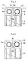
- left, right, front, “rear,” “upper” and “lower” as used herein are based on FIG. 3; the term “left” refers to the left-hand side of FIG. 3, the term “right” to the right-hand side of the same, the term “front” to the front side of the plane of the same drawing, the term “rear” to the rear side thereof, the term “upper” to the upper side of the same drawing, and the term “lower” to the lower side of the same.
- the drawings show a layered evaporator embodying the invention for use in motor vehicle air conditioners.
- FIGS. 1 to 3 show a layered heat exchanger of the invention, i.e., a first embodiment, for use as a layered evaporator 1.
- the evaporator 1 is made from aluminum (inclusive of aluminum alloys) and comprises a multiplicity of intermediate plates 2 arranged side by side in superposed layers, and end plates 3 positioned respectively at opposite ends, in the direction of superposition, of the assembly of the intermediate plates 2.
- Each intermediate plate 2 is provided, on one side of each of the upper and lower ends thereof, with a pair of front and rear cuplike protrusions 21, 23 having respective tank-forming recesses inside thereof and respective refrigerant passage holes 22, 24 formed in their bottom portions.
- the intermediate portion of the height of the plate 2 provides a bulging portion having an inside recess for forming a refrigerant channel.
- the left plate 3 is provided, on the outer side of each of the upper and lower ends thereof, with a pair of front and rear cuplike protrusions 25, 27 having respective refrigerant channel forming recesses inside thereof and respective refrigerant passage holes 26, 28 formed in their bottom portions.
- All the intermediate plates 2 are arranged in superposed layers, with the recesses of each pair of adjacent plates 2 opposed to each other, and the left and right end plates 3 are fitted over the respective opposite ends, in the direction of superposition, of the assembly of the plates 2 to form parallel flat tubular portions 4 and tank portions 5, 6 communicating respectively with the upper and lower ends of the flat tubular porions 4.
- Corrugated fins 7 are interposed between each pair of adjacent flat tubular portions 4, 4 and between each of the left and right end plates 3 and the flat tubular portion 4 immediately adjacent to the end plate.
- the left end plate 3 is covered, over the outer surface of the upper end portion thereof, with a pipe mount plate 10 having a refrigerant discharge pipe socket 11 and a refrigerant introduction pipe socket 12 formed by burring and arranged side by side respectively at front and rear.
- the pipe mount plate 10 has a cutout 13 positioned between the refrigerant discharge pipe socket 11 and the refrigerant introduction pipe socket 12.
- the cutout 13 has an upper end 13a extending to a level above the upper end of the refrigerant discharge pipe socket 11 and the upper end of the refrigerant introduction pipe socket 12, and has a lower end left open downward at the lower end of the plate 10 to provide an open end portion 13c.
- the pipe socket 11 on the refrigerant discharge side of the pipe mount plate 10 is larger than the pipe socket 12 on the refrigerant introduction side of the plate 10 in diameter, so that the upper end 13a of the cutout 13 extends to a level above the upper end of the pipe socket 12.
- the left end plate 3 has parallel reinforcing ribs 29 under the portion thereof where the pipe mount plate 10 is attached.
- the intermediate plates 2 and the left and right end plates 3, 3 are made from an aluminum brazing sheet, while inner fins (not shown), the corrugated fins 7 and the pipe mount plate 10 are made from aluminum.
- the heat exchange portion of the layered evaporator 1 described is fabricated by assembling a required number of intermediate plates 2 and opposite side end plates 3 in superposed layers, with a pipe mount plate 10 fitted over the outer surface of upper end portion of the left end plate 3, holding all of these components by a jig at opposite sides of the assembly from outside and collectively brazing the resulting assembly in this state in a furnace for as by the vacuum brazing method or flux brazing method.
- the upper end 13a of the cutout 13 extends to a level above the upper end of the refrigerant discharge pipe socket 11 and the upper end of the refrigerant introduction pipe socket 12. This obviates the likelihood that a shortcut channel will occur between the two pipe sockets 11, 12.
- a refrigerant discharge pipe 16 is inserted into the refrigerant discharge pipe socket 11 at the front on the mount plate 10 and joined thereto with a brazing material 17.
- a refrigerant introduction pipe 15 is inserted into the refrigerant introduction pipe socket 12 in the rear on the plate 10 and joined thereto with the brazing material 17.
- a refrigerant is introduced into the left-end rear portion of upper tank 5 of the heat exchange portion from the introduction pipe 15, then passed through the refrigerant channels inside the heat exchange portion zigzag in its entirety and finally discharged from discharge pipe 16 at the left-end front portion of the upper tank 5.
- air or air stream flows from the front of the evaporator heat exchange portion toward the rear side thereof to pass through the clearances provided with the corrugated fins 7 and formed between the adjacent flat tubular portions 4, 4 of the heat exchange portion and between each end plate 3 and the tubular porion 4 immediately adjacent thereto, and is subjected to efficient heat exchange with the refrigerant through the walls of the intermediate plates 2 and the corrugated fins 7.
- FIG. 4 shows a second embodiment of the invention, which differs from the first embodiment in that the cutout 13 formed in the pipe mount plate 10 and positioned between the refrigerant introduction pipe socket 12 and the refrigerant discharge pipe socket 11 on the plate 10 has an upper end left open upward at the upper end of the mount plate 10 to provide an open end portion 13c, and a lower end 13b extending to a level below a lower end of the refrigerant introduction pipe socket 12 and a lower end of the refrigerant discharge pipe socket 11.
- the lower end 13b of the cutout 13 extends to a level below the lower end of the refrigerant discharge pipe socket 11 and the lower end of the refrigerant introduction pipe socket 12. This obviates the likelihood that a shortcut channel will occur between the two pipe sockets 11, 12.
- the open upper end portion 13c of the cutout 13 in the illustrated pipe mount plate 10 has a relatively small width, whereas the open upper end portion 13c of the cutout 13 may have an increased width as indicated in two-dot chain lines in FIG. 4 as is the case with the first embodiment.
- the second embodiment has the same construction as the first, so that like parts are designated by like reference numerals throughout the drawings concerned.
- the pipe mount plate 10 having the cutout 13 and covering the upper-end outer surface of the left end plate 3 of the layered evaporator 1 is brazed to the end plate 3 according to the embodiments described, the pipe mount plate 10 may alternatively cover the upper-end outer surface of the right end plate 3 and brazed to this end plate.
- tank portions 5, 6 are provided respectively at the upper and lower sides of the assembly of superposed intermediate plates 2 in the case of the illustrated heat exchanger, the present invention is similarly applicable to layered heat exchangers wherein tank portions are provided only at one of the upper and lower sides of the layered assembly of intermediate plates 2.
- the layered heat exchanger of the present invention is not only useful as a layered evaporator for use in motor vehicle air conditioners like the foregoing embodiments but also similarly usable in oil coolers, aftercoolers, radiators, etc.
Applications Claiming Priority (2)
| Application Number | Priority Date | Filing Date | Title |
|---|---|---|---|
| JP2000055648 | 2000-03-01 | ||
| JP2000055648A JP4328445B2 (ja) | 2000-03-01 | 2000-03-01 | 積層型熱交換器 |
Publications (3)
| Publication Number | Publication Date |
|---|---|
| EP1130349A2 true EP1130349A2 (de) | 2001-09-05 |
| EP1130349A3 EP1130349A3 (de) | 2002-06-12 |
| EP1130349B1 EP1130349B1 (de) | 2003-11-19 |
Family
ID=18576737
Family Applications (1)
| Application Number | Title | Priority Date | Filing Date |
|---|---|---|---|
| EP01105022A Expired - Lifetime EP1130349B1 (de) | 2000-03-01 | 2001-03-01 | Wärmetauscher mit gestapelten Platten |
Country Status (7)
| Country | Link |
|---|---|
| US (1) | US6453990B2 (de) |
| EP (1) | EP1130349B1 (de) |
| JP (1) | JP4328445B2 (de) |
| AT (1) | ATE254750T1 (de) |
| DE (1) | DE60101235T2 (de) |
| ES (1) | ES2210049T3 (de) |
| TW (1) | TW550134B (de) |
Cited By (2)
| Publication number | Priority date | Publication date | Assignee | Title |
|---|---|---|---|---|
| EP1548384A2 (de) * | 2003-11-11 | 2005-06-29 | Sanden Corporation | Mehrstromwärmetauscher in Stapelbauweise |
| EP1692449A1 (de) * | 2003-11-14 | 2006-08-23 | Showa Denko K.K. | Verdampfer und herstellungsverfahren dafür |
Families Citing this family (9)
| Publication number | Priority date | Publication date | Assignee | Title |
|---|---|---|---|---|
| JP4533726B2 (ja) * | 2003-11-14 | 2010-09-01 | 昭和電工株式会社 | エバポレータおよびその製造方法 |
| JP4667077B2 (ja) * | 2004-03-09 | 2011-04-06 | 昭和電工株式会社 | ジョイントプレート半製品、ジョイントプレート、ジョイントプレートの製造方法および熱交換器 |
| JP2005337573A (ja) * | 2004-05-26 | 2005-12-08 | Sanden Corp | 熱交換器 |
| JP5154842B2 (ja) * | 2007-06-12 | 2013-02-27 | カルソニックカンセイ株式会社 | 熱交換器の継ぎ手構造 |
| JP5142109B2 (ja) * | 2008-09-29 | 2013-02-13 | 株式会社ケーヒン・サーマル・テクノロジー | エバポレータ |
| FR3018601B1 (fr) * | 2014-03-12 | 2018-04-27 | Valeo Systemes Thermiques | Dispositif de connexion pour echangeur de chaleur et echangeur de chaleur equipe dudit dispositif de connexion |
| JP6528283B2 (ja) * | 2016-03-28 | 2019-06-12 | パナソニックIpマネジメント株式会社 | 熱交換器 |
| JP2018044710A (ja) * | 2016-09-14 | 2018-03-22 | カルソニックカンセイ株式会社 | 熱交換器 |
| JP6862773B2 (ja) * | 2016-11-07 | 2021-04-21 | 株式会社デンソー | 熱交換器 |
Citations (4)
| Publication number | Priority date | Publication date | Assignee | Title |
|---|---|---|---|---|
| JPS6246195A (ja) * | 1985-08-22 | 1987-02-28 | Diesel Kiki Co Ltd | 積層型熱交換器 |
| EP0347961A1 (de) * | 1988-06-20 | 1989-12-27 | Itt Industries, Inc. | Plattenwärmeaustauscher |
| DE9420659U1 (de) * | 1994-12-23 | 1995-02-09 | Thermal Waerme Kaelte Klima | Heizungswärmetauscher für Kraftfahrzeuge und angepaßter Wasserkasten |
| EP0872698A2 (de) * | 1997-04-15 | 1998-10-21 | Zexel Corporation | Lamellenwärmetauscher |
Family Cites Families (1)
| Publication number | Priority date | Publication date | Assignee | Title |
|---|---|---|---|---|
| JP2000329493A (ja) * | 1999-05-20 | 2000-11-30 | Toyo Radiator Co Ltd | 積層型熱交換器 |
-
2000
- 2000-03-01 JP JP2000055648A patent/JP4328445B2/ja not_active Expired - Fee Related
-
2001
- 2001-02-26 TW TW090104331A patent/TW550134B/zh not_active IP Right Cessation
- 2001-02-28 US US09/794,014 patent/US6453990B2/en not_active Expired - Lifetime
- 2001-03-01 DE DE60101235T patent/DE60101235T2/de not_active Expired - Fee Related
- 2001-03-01 AT AT01105022T patent/ATE254750T1/de not_active IP Right Cessation
- 2001-03-01 EP EP01105022A patent/EP1130349B1/de not_active Expired - Lifetime
- 2001-03-01 ES ES01105022T patent/ES2210049T3/es not_active Expired - Lifetime
Patent Citations (4)
| Publication number | Priority date | Publication date | Assignee | Title |
|---|---|---|---|---|
| JPS6246195A (ja) * | 1985-08-22 | 1987-02-28 | Diesel Kiki Co Ltd | 積層型熱交換器 |
| EP0347961A1 (de) * | 1988-06-20 | 1989-12-27 | Itt Industries, Inc. | Plattenwärmeaustauscher |
| DE9420659U1 (de) * | 1994-12-23 | 1995-02-09 | Thermal Waerme Kaelte Klima | Heizungswärmetauscher für Kraftfahrzeuge und angepaßter Wasserkasten |
| EP0872698A2 (de) * | 1997-04-15 | 1998-10-21 | Zexel Corporation | Lamellenwärmetauscher |
Non-Patent Citations (1)
| Title |
|---|
| PATENT ABSTRACTS OF JAPAN vol. 011, no. 234 (M-611), 30 July 1987 (1987-07-30) -& JP 62 046195 A (DIESEL KIKI CO LTD), 28 February 1987 (1987-02-28) * |
Cited By (4)
| Publication number | Priority date | Publication date | Assignee | Title |
|---|---|---|---|---|
| EP1548384A2 (de) * | 2003-11-11 | 2005-06-29 | Sanden Corporation | Mehrstromwärmetauscher in Stapelbauweise |
| EP1548384A3 (de) * | 2003-11-11 | 2006-05-24 | Sanden Corporation | Mehrstromwärmetauscher in Stapelbauweise |
| EP1692449A1 (de) * | 2003-11-14 | 2006-08-23 | Showa Denko K.K. | Verdampfer und herstellungsverfahren dafür |
| EP1692449A4 (de) * | 2003-11-14 | 2012-05-30 | Showa Denko Kk | Verdampfer und herstellungsverfahren dafür |
Also Published As
| Publication number | Publication date |
|---|---|
| JP4328445B2 (ja) | 2009-09-09 |
| JP2001241881A (ja) | 2001-09-07 |
| DE60101235T2 (de) | 2004-08-26 |
| EP1130349A3 (de) | 2002-06-12 |
| ATE254750T1 (de) | 2003-12-15 |
| US6453990B2 (en) | 2002-09-24 |
| DE60101235D1 (de) | 2003-12-24 |
| EP1130349B1 (de) | 2003-11-19 |
| TW550134B (en) | 2003-09-01 |
| ES2210049T3 (es) | 2004-07-01 |
| US20010018966A1 (en) | 2001-09-06 |
Similar Documents
| Publication | Publication Date | Title |
|---|---|---|
| JP3814917B2 (ja) | 積層型蒸発器 | |
| EP1130349B1 (de) | Wärmetauscher mit gestapelten Platten | |
| US5685075A (en) | Method for brazing flat tubes of laminated heat exchanger | |
| JPH08254399A (ja) | 熱交換器 | |
| JP3591102B2 (ja) | 積層型熱交換器 | |
| WO2005098339A1 (en) | Heat exchanger having an improved baffle | |
| JPH05272889A (ja) | 熱交換器 | |
| US7328739B2 (en) | Heat exchanger for vehicle | |
| US7077193B2 (en) | Compound type heat exchanger | |
| JP4713211B2 (ja) | 熱交換器 | |
| EP0805330B1 (de) | Wärmetauscher, der eine Dichtheitsprüfung einer durch eine Trennplatte getrennte Endkammer ermöglicht | |
| US20100206533A1 (en) | Heat exchanger | |
| JP4866571B2 (ja) | 熱交換器 | |
| JP3674060B2 (ja) | 積層型熱交換器の製造方法 | |
| JPH11337292A (ja) | 熱交換器 | |
| JP3136220B2 (ja) | パラレルフロー熱交換器 | |
| JPH07103683A (ja) | 熱交換器 | |
| JPH0717962Y2 (ja) | 熱交換器 | |
| JPH10197188A (ja) | 熱交換器 | |
| JP2003004338A (ja) | 熱交換器 | |
| JPH07305992A (ja) | 熱交換器のヘッダタンク | |
| JPH09243290A (ja) | アルミニウム合金製熱交換器 | |
| JPH05157486A (ja) | 熱交換器 | |
| JPH10253283A (ja) | アルミニウム合金製熱交換器 | |
| JP3311149B2 (ja) | アルミニウム合金製熱交換器 |
Legal Events
| Date | Code | Title | Description |
|---|---|---|---|
| PUAI | Public reference made under article 153(3) epc to a published international application that has entered the european phase |
Free format text: ORIGINAL CODE: 0009012 |
|
| AK | Designated contracting states |
Kind code of ref document: A2 Designated state(s): AT BE CH CY DE DK ES FI FR GB GR IE IT LI LU MC NL PT SE TR |
|
| AX | Request for extension of the european patent |
Free format text: AL;LT;LV;MK;RO;SI |
|
| PUAL | Search report despatched |
Free format text: ORIGINAL CODE: 0009013 |
|
| AK | Designated contracting states |
Kind code of ref document: A3 Designated state(s): AT BE CH CY DE DK ES FI FR GB GR IE IT LI LU MC NL PT SE TR |
|
| AX | Request for extension of the european patent |
Free format text: AL;LT;LV;MK;RO;SI |
|
| 17P | Request for examination filed |
Effective date: 20021011 |
|
| 17Q | First examination report despatched |
Effective date: 20021223 |
|
| AKX | Designation fees paid |
Designated state(s): AT BE CH CY DE DK ES FI FR GB GR IE IT LI LU MC NL PT SE TR |
|
| GRAH | Despatch of communication of intention to grant a patent |
Free format text: ORIGINAL CODE: EPIDOS IGRA |
|
| GRAS | Grant fee paid |
Free format text: ORIGINAL CODE: EPIDOSNIGR3 |
|
| GRAA | (expected) grant |
Free format text: ORIGINAL CODE: 0009210 |
|
| AK | Designated contracting states |
Kind code of ref document: B1 Designated state(s): AT BE CH CY DE DK ES FI FR GB GR IE IT LI LU MC NL PT SE TR |
|
| PG25 | Lapsed in a contracting state [announced via postgrant information from national office to epo] |
Ref country code: CY Free format text: LAPSE BECAUSE OF FAILURE TO SUBMIT A TRANSLATION OF THE DESCRIPTION OR TO PAY THE FEE WITHIN THE PRESCRIBED TIME-LIMIT Effective date: 20031119 Ref country code: CH Free format text: LAPSE BECAUSE OF FAILURE TO SUBMIT A TRANSLATION OF THE DESCRIPTION OR TO PAY THE FEE WITHIN THE PRESCRIBED TIME-LIMIT Effective date: 20031119 Ref country code: LI Free format text: LAPSE BECAUSE OF FAILURE TO SUBMIT A TRANSLATION OF THE DESCRIPTION OR TO PAY THE FEE WITHIN THE PRESCRIBED TIME-LIMIT Effective date: 20031119 Ref country code: BE Free format text: LAPSE BECAUSE OF FAILURE TO SUBMIT A TRANSLATION OF THE DESCRIPTION OR TO PAY THE FEE WITHIN THE PRESCRIBED TIME-LIMIT Effective date: 20031119 Ref country code: FI Free format text: LAPSE BECAUSE OF FAILURE TO SUBMIT A TRANSLATION OF THE DESCRIPTION OR TO PAY THE FEE WITHIN THE PRESCRIBED TIME-LIMIT Effective date: 20031119 Ref country code: NL Free format text: LAPSE BECAUSE OF FAILURE TO SUBMIT A TRANSLATION OF THE DESCRIPTION OR TO PAY THE FEE WITHIN THE PRESCRIBED TIME-LIMIT Effective date: 20031119 Ref country code: TR Free format text: LAPSE BECAUSE OF FAILURE TO SUBMIT A TRANSLATION OF THE DESCRIPTION OR TO PAY THE FEE WITHIN THE PRESCRIBED TIME-LIMIT Effective date: 20031119 |
|
| REG | Reference to a national code |
Ref country code: GB Ref legal event code: FG4D |
|
| REG | Reference to a national code |
Ref country code: CH Ref legal event code: EP |
|
| REF | Corresponds to: |
Ref document number: 60101235 Country of ref document: DE Date of ref document: 20031224 Kind code of ref document: P |
|
| REG | Reference to a national code |
Ref country code: IE Ref legal event code: FG4D |
|
| REG | Reference to a national code |
Ref country code: SE Ref legal event code: TRGR |
|
| PG25 | Lapsed in a contracting state [announced via postgrant information from national office to epo] |
Ref country code: DK Free format text: LAPSE BECAUSE OF FAILURE TO SUBMIT A TRANSLATION OF THE DESCRIPTION OR TO PAY THE FEE WITHIN THE PRESCRIBED TIME-LIMIT Effective date: 20040219 Ref country code: GR Free format text: LAPSE BECAUSE OF FAILURE TO SUBMIT A TRANSLATION OF THE DESCRIPTION OR TO PAY THE FEE WITHIN THE PRESCRIBED TIME-LIMIT Effective date: 20040219 |
|
| PG25 | Lapsed in a contracting state [announced via postgrant information from national office to epo] |
Ref country code: LU Free format text: LAPSE BECAUSE OF NON-PAYMENT OF DUE FEES Effective date: 20040301 Ref country code: IE Free format text: LAPSE BECAUSE OF NON-PAYMENT OF DUE FEES Effective date: 20040301 |
|
| PG25 | Lapsed in a contracting state [announced via postgrant information from national office to epo] |
Ref country code: MC Free format text: LAPSE BECAUSE OF NON-PAYMENT OF DUE FEES Effective date: 20040331 |
|
| NLV1 | Nl: lapsed or annulled due to failure to fulfill the requirements of art. 29p and 29m of the patents act | ||
| REG | Reference to a national code |
Ref country code: CH Ref legal event code: PL |
|
| REG | Reference to a national code |
Ref country code: ES Ref legal event code: FG2A Ref document number: 2210049 Country of ref document: ES Kind code of ref document: T3 |
|
| ET | Fr: translation filed | ||
| PLBE | No opposition filed within time limit |
Free format text: ORIGINAL CODE: 0009261 |
|
| STAA | Information on the status of an ep patent application or granted ep patent |
Free format text: STATUS: NO OPPOSITION FILED WITHIN TIME LIMIT |
|
| 26N | No opposition filed |
Effective date: 20040820 |
|
| REG | Reference to a national code |
Ref country code: IE Ref legal event code: MM4A |
|
| PGFP | Annual fee paid to national office [announced via postgrant information from national office to epo] |
Ref country code: GB Payment date: 20070228 Year of fee payment: 7 |
|
| PGFP | Annual fee paid to national office [announced via postgrant information from national office to epo] |
Ref country code: SE Payment date: 20070307 Year of fee payment: 7 |
|
| PGFP | Annual fee paid to national office [announced via postgrant information from national office to epo] |
Ref country code: AT Payment date: 20070313 Year of fee payment: 7 |
|
| PGFP | Annual fee paid to national office [announced via postgrant information from national office to epo] |
Ref country code: ES Payment date: 20070329 Year of fee payment: 7 |
|
| PG25 | Lapsed in a contracting state [announced via postgrant information from national office to epo] |
Ref country code: PT Free format text: LAPSE BECAUSE OF NON-PAYMENT OF DUE FEES Effective date: 20040419 |
|
| PGFP | Annual fee paid to national office [announced via postgrant information from national office to epo] |
Ref country code: IT Payment date: 20070528 Year of fee payment: 7 |
|
| PGFP | Annual fee paid to national office [announced via postgrant information from national office to epo] |
Ref country code: FR Payment date: 20070308 Year of fee payment: 7 |
|
| EUG | Se: european patent has lapsed | ||
| GBPC | Gb: european patent ceased through non-payment of renewal fee |
Effective date: 20080301 |
|
| PG25 | Lapsed in a contracting state [announced via postgrant information from national office to epo] |
Ref country code: AT Free format text: LAPSE BECAUSE OF NON-PAYMENT OF DUE FEES Effective date: 20080301 |
|
| REG | Reference to a national code |
Ref country code: FR Ref legal event code: ST Effective date: 20081125 |
|
| PG25 | Lapsed in a contracting state [announced via postgrant information from national office to epo] |
Ref country code: SE Free format text: LAPSE BECAUSE OF NON-PAYMENT OF DUE FEES Effective date: 20080302 |
|
| PG25 | Lapsed in a contracting state [announced via postgrant information from national office to epo] |
Ref country code: FR Free format text: LAPSE BECAUSE OF NON-PAYMENT OF DUE FEES Effective date: 20080331 |
|
| REG | Reference to a national code |
Ref country code: ES Ref legal event code: FD2A Effective date: 20080303 |
|
| PG25 | Lapsed in a contracting state [announced via postgrant information from national office to epo] |
Ref country code: GB Free format text: LAPSE BECAUSE OF NON-PAYMENT OF DUE FEES Effective date: 20080301 |
|
| PG25 | Lapsed in a contracting state [announced via postgrant information from national office to epo] |
Ref country code: ES Free format text: LAPSE BECAUSE OF NON-PAYMENT OF DUE FEES Effective date: 20080303 |
|
| PG25 | Lapsed in a contracting state [announced via postgrant information from national office to epo] |
Ref country code: IT Free format text: LAPSE BECAUSE OF NON-PAYMENT OF DUE FEES Effective date: 20080301 |
|
| PGFP | Annual fee paid to national office [announced via postgrant information from national office to epo] |
Ref country code: DE Payment date: 20090226 Year of fee payment: 9 |
|
| PG25 | Lapsed in a contracting state [announced via postgrant information from national office to epo] |
Ref country code: DE Free format text: LAPSE BECAUSE OF NON-PAYMENT OF DUE FEES Effective date: 20101001 |