EP1126085A1 - Machine a travailler pourvue d'un condensateur - Google Patents
Machine a travailler pourvue d'un condensateur Download PDFInfo
- Publication number
- EP1126085A1 EP1126085A1 EP00913009A EP00913009A EP1126085A1 EP 1126085 A1 EP1126085 A1 EP 1126085A1 EP 00913009 A EP00913009 A EP 00913009A EP 00913009 A EP00913009 A EP 00913009A EP 1126085 A1 EP1126085 A1 EP 1126085A1
- Authority
- EP
- European Patent Office
- Prior art keywords
- condenser
- condensers
- work
- power
- working machine
- Prior art date
- Legal status (The legal status is an assumption and is not a legal conclusion. Google has not performed a legal analysis and makes no representation as to the accuracy of the status listed.)
- Granted
Links
Images


Classifications
-
- E—FIXED CONSTRUCTIONS
- E02—HYDRAULIC ENGINEERING; FOUNDATIONS; SOIL SHIFTING
- E02F—DREDGING; SOIL-SHIFTING
- E02F9/00—Component parts of dredgers or soil-shifting machines, not restricted to one of the kinds covered by groups E02F3/00 - E02F7/00
- E02F9/20—Drives; Control devices
- E02F9/2058—Electric or electro-mechanical or mechanical control devices of vehicle sub-units
- E02F9/2062—Control of propulsion units
- E02F9/2075—Control of propulsion units of the hybrid type
-
- E—FIXED CONSTRUCTIONS
- E02—HYDRAULIC ENGINEERING; FOUNDATIONS; SOIL SHIFTING
- E02F—DREDGING; SOIL-SHIFTING
- E02F9/00—Component parts of dredgers or soil-shifting machines, not restricted to one of the kinds covered by groups E02F3/00 - E02F7/00
- E02F9/20—Drives; Control devices
- E02F9/2058—Electric or electro-mechanical or mechanical control devices of vehicle sub-units
- E02F9/2091—Control of energy storage means for electrical energy, e.g. battery or capacitors
Definitions
- the present invention relates to a working machine such as an excavator for actuating a working member such as a boom making use of electric power generated by a generator.
- a hydraulic pump is driven by making use of power of an engine mounted for self-traveling, and operating oil discharged out of the hydraulic pump is supplied to hydraulic actuators such as a swing actuator, a boom cylinder, an arm cylinder or the like to thereby drive various parts.
- this excavator has may working patterns such as excavation, slope finishing, leveling, hardening, scattering, crane traveling, etc. Further, loads (necessary power) greatly differ with each work, and accordingly, condensing ability required for a condenser varies.
- a condenser In case of excavation work, time for carrying out one operation is short, but operation of each actuator is quick, and acceleration and deceleration are frequently carried out, and therefore a peak value of load and a variation of load are great. Accordingly, a condenser must have the ability for carrying out charging and discharging operations by a large current in a comparatively short period of time. On the other hand, in case of slope finishing work or the like, time for carrying out one operation is long, but a peak value of load and a variation of load are small, and therefore, a condenser must have the ability capable of supplying power to an electrically-operated actuator little by little over a long period of time.
- the secondary batteries such as the lead battery and the nickel hydrogen battery have the characteristics that the energy density (stored energy per unit weight) is high, whereas the life of charge-discharge cycle is short, and the power density (output per unit weight) is low.
- a large capacity capacitor including the electric double layer condenser has the characteristics that the power density (output per unit weight) is high and the life of charge-discharge cycle is long, whereas the energy density (stored energy per unit weight) is low.
- the present invention employed the following constitution.
- the present invention provides a working machine comprising a generator, and an electrically-operated actuator in which power for actuating working members is generated by electric power generated by the generator, the working machine comprising a plurality of condensers for carrying out charging of electric power generated by the generator and supplying of electric power to the electrically-operated actuator, and a switching means for selectively switching the condensers used out of these condensers.
- the "electrically-operated actuator for generating power for operating working members” includes, in addition to those directly connected to the working members to directly drive the working members, those for swing hydraulic pump included in a hydraulic circuit for driving the working members.
- a condenser suitable for the load characteristic of an electrically-operated actuator in the work being carried out actually is selected out of a plurality of condensers whereby the individual condenser can satisfy the charge-discharge conditions require by the work without making it large.
- the first condenser and the second condenser are selected respectively whereby even the condensers are small in size, the charge-discharging suited to the work can be carried out.
- Switching of the condensers may be carried out, for example, in accordance with switching operation of a selective switch by an operator, or may be automatically carried out.
- power detection means for detecting total necessary power of the electrically-operated actuator and switching control means for controlling switching of using condensers on the bass of the detected total necessary power are provided. According to this constitution, selection of proper condensers can be automatically done on the basis of power required actually.
- a first condenser and a second condenser which is higher in output per unit weight and is lower in stored energy per unit weight than the first condenser are included as the condensers, and said switching control means is constituted such that where the detected total necessary power is within the range of power preset, the first condenser is selected, and where the detected total necessary power is larger than said range of power or smaller than said range of power, the second condenser is selected, then at the time of work for which variation of power is large and charge-discharging by a large current is required, the second condenser suited thereto is automatically selected, and at the time of work for which variation of power is small, the first condenser capable of charge-discharging for a long period of time are automatically selected, respectively.
- an operating member for operating the electrically-operated actuator for operating the electrically-operated actuator, work discriminating means for discriminating work contents from the operating state of the operating member, and switching control means for controlling switching of using condensers according to the work contents discriminated are provided.
- the actual work contents are discriminated on the basis of the operating contents of the operating member, and the condenser suited to the work contents is automatically selected and switched.
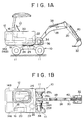
- a excavator shown in FIG. 1 is provided with a lower traveling body 10 having a tire 11 for traveling, and an upper rotating body 12 is installed capable of being turned about the vertical axis on the lower traveling body 10.
- the upper rotating body 12 is provided with a cabin 13, and has a first condenser 14A, a second condenser 14B, a fuel tank 16, a generator 18, an engine 20 and so on mounted thereon.
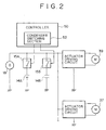
- the generator 18 is provided to convert output of the engine 20 into electric energy to supply it to a driving circuit of electrically-operated actuators (described in detail later) as shown in FIG. 2.
- the first condenser 14A and the second condenser 14B are provided to suitably store a surplus part of electric power generated by the generator 18 to suitably release a short part and supply it the actuator driving circuits.
- release switches (switching means) 15A, 15B as shown in FIG. 2 are individually interposed between the generator 18 and the actuator driving circuits, and the condensers 14A, 14B, and either one contact of the release switches 15A, 15B is closed whereby the condensers to be used can be selectively switched.
- the first condenser 14A is constituted, for example, like a secondary battery, by a condenser whose power density (output per unit weight) is relatively low and energy density (stored energy per unit weight) is high.
- the second condenser 14B is constituted, for example, like a large capacity capacitor, by a condenser whose power density is higher than the first condenser 14A and energy density is lower.
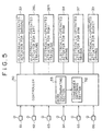
- This excavator is provided, as the electrically-operated actuators, as shown in FIG. 3, with an electrically-operated actuator for swinging 22, an electrically-operated actuator for left traveling 26L, an electrically-operated actuator for right traveling 26R, an electrically-operated actuator for boom driving 34, an electrically-operated actuator for arm driving 37, and an electrically-operated actuator for bucket driving 39, these actuators being constituted by electric motors in this embodiment.
- the electrically-operated actuator for swing and driving 22 is connected to a swinging mechanism 24 through a reduction unit 23, and by the operation of the electrically-operated actuator 22, swinging of the entire upper rotating body 12 is carried out.
- the electrically-operated actuator for left traveling 26L, and the electrically-operated actuator for right traveling 26R are respectively connected to the front left and right tires 11 through a left reduction unit 25L and a right reduction unit 25R, and by the operation of these electrically-operated actuators 26L, 26R, the entire hydraulic excavator is traveled.
- the electrically-operated actuator for boom driving 34 is provided so that by the operation thereof, the boom 28 mounted on the front end of the upper rotating body 12 is turned and driven (risen and fallen movement) about the axis in the width direction.
- the electrically-operated actuator for arm driving 37 is provided so that by the operation thereof, a hydraulic pump of an arm cylinder driving hydraulic circuit not shown is operated whereby an arm cylinder 38 is expanded and contracted to turn an arm 30 mounted on the extreme end of the boom 28 about the axis in the width direction.
- the electrically-operated actuator for bucket driving 39 is provided so that by the operation thereof, a hydraulic pump of a bucket cylinder driving hydraulic circuit not shown is operated whereby a bucket cylinder 40 is expanded and contracted to turn a bucket 32 mounted on the extreme end of the arm 30 about the axis in the width direction.
- the electrically-operated actuator for boom driving 34 is not only directly connected to the boom 28 to directly drive it but also drives a hydraulic pump of a boom driving hydraulic circuit to indirectly drive the boom, similarly to the electrically-operated actuator for arm driving 37.
- the electrically-operated actuator for arm driving 37 and the electrically-operated actuator for bucket driving 39 may be directly connected to the arm 30 and the bucket 32 to directly drive them.
- Power detecting sensors as shown in FIG. 3 are individually provided on the electrically-driven actuators so that power (motor load) of the electrically-driven actuators are individually detected by the sensors (Step S1 in FIG. 4).
- These power detecting sensors may be of voltage sensors for detecting an electrical load of a motor or a current sensor, or may be torque sensors for detecting a mechanical load of a motor or angular velocity sensors.
- a detection signal of the power detecting sensors is input into a controller 50 shown in FIG. 3.
- the controller 50 is constituted by a microcomputer or the like to carry out the start of the engine and the driving control of the electrically-operated actuators and to carry out the switching control of the condensers 14A, 14B on the basis of the detection signal of the power detecting sensors, and is provided with a power operation (computing) section 51 and a condenser switching section (switching control means) 52 for the switching control.
- the power operation section 51 is provided to operate the sum total P of necessary power for the actuators detected by the power detecting sensors, that is, the total necessary power during working (Step S2 in FIG. 4), to constitute power detection means along with the power detecting sensors.
- the condenser switching section 52 selects a condenser to be used out of both the condensers 14A, 14B on the basis of the sum total P of the actuator power operated by the power operation section 51 and outputs a signal to the release switches 15A, 15B (FIG. 2) corresponding to the selected condenser to switch the condenser into a using state.
- the condenser switching section 52 selects where the sum total P of the actuator power is below the preset upper limit value P1 and above the preset lower limit value P2 (NO in Steps S3 and S4), the first condenser 14A (Step S5), and selects, where the sum total P of the actuator power is above the preset upper limit value P1 (YES in Step S3) or below the preset lower limit value P2 (YES in Step S4), the second condenser 14B (Step S6).
- the upper limit value P1 is set to a value higher than the power corresponding to electric power generated by the operation of the engine 20 and the generator 18, and the lower limit value P2 is set to a value lower than the power corresponding to electric power generated by the operation of the engine 20 and the generator 18.
- the first condenser 14A is selected. Since the first condenser 14A is higher in energy density than the second condenser 14B, even if the first condenser 14A is small in size, necessary electric power can be supplied continuously to the electrically-operated actuators during working for a long period of time, for example, such as the slope finishing or finishing with swing.
- the second condenser 14B is selected. Since the second condenser 14B is higher in power density than the first condenser 14B, even if the second condenser 14B is small in size, the request that charge-discharging at a large current be desired to be carried out can be fulfilled.
- the condenser used is switched on the basis of the sum total of actuator power required actually, whereby it is possible to fulfill charge-discharging request for such a work as described while individual condensers are of a light-weight and a small type, in work for a long period of time or in work for a short period of time in which a load variation is large.
- the hardware constitution according to this embodiment is exactly the same as that of the aforementioned first embodiment, and a description thereof is omitted.
- operating levers 61, 62, 63, 64, 65, and 66 for individually operating the electrically-operated actuators 22, 26L, 26R, 34, 37, and 39 are provided in the cabin 13, and an instruction(s) signal produced by operation of the operating levers 61 to 66 is input into a controller 50, and the controller 50 is constituted so that the driving of the electrically-operated actuators is controlled on the basis of the instruction(s) signal, and in addition, the controller 50 is provided with a work discriminating section 53 for discriminating actual work contents on the basis of the instruction(s) signal (operating contents).
- the average values of the magnitude of the operating quantities of the operating levers 64, 65, and 66 within the fixed time are individually obtained, which is set as the average value of boom operating quantity ch6, the average value of arm operating quantity ch7, and the average value of bucket operating quantity ch8.
- STEP 1 The complicatedness display quantity ch2 of bucket operation is compared with the fixed value Th1 predetermined corresponding thereto. If ch2 ⁇ Th1 results, work being done is judged to be scattering work, and in other cases, the step shifts to STEP 2.
- the "scattering work” termed herein is to repeat, at high speed, work in which by simultaneous operation of the bucket, arm and boom, earth is scooped into the bucket, which is scattered by operation of the bucket.
- STEP 2 Where the conditions of STEP 1 are not realized, the boom operation complicatedness display quantity ch1, the high speed swing time ch3, and the bucket/arm stop time ch5 are compared with the fixed values Th2, Th3, and Th4, respectively. If ch1 ⁇ Th2, ch3 ⁇ Th3, and ch5 ⁇ Th4 result, work being done is judged to be "hardening work", and in other cases, the step shifts to STEP 3.
- the "hardening work” is work in which up-downward movement of the boom is repeated to throw the bucket on the ground many times to harden the ground, the load of the actuator being rapidly increased and decreased shockingly.
- STEP 3 Where the conditions of STEP 2 are not realized, the bucket operation complicatedness display quantity ch2, the bucket/arm stop time ch5, the boom reverse operation time ch4, and a total value of the average value of the arm operating quantities and the average value of the boom operating quantities (ch7+ch8) are compared with the predetermined fixed values Th5, Th6, Th7 and Th8, respectively. If ch2 ⁇ Th5, ch5 ⁇ Th6, and ch4 ⁇ Th7, and (ch7+ch8) ⁇ Th8 result, work being done is judged to be "slope finishing work", and in other cases, the step shifts to STEP 4.
- the "slope finishing work” termed herein is work in which by simultaneous operation of the bucket, the arm and the boom, the arm and the boom are operated while placing the bucket along the slanting surface to scrape the slanting surface by the bucket.
- STEP 4 Where the conditions of STEP 3 are not realized, the boom operation complicatedness display quantity chl, the bucket operation complicatedness display quantity ch2, the high speed swing time ch3, the bucket/arm stop time ch5, and a total value of the average value of the arm operating quantities and the average value of the boom operating quantities (ch7+ch8) are compared with the predetermined fixed values Th9, Th10, Th11, Thl2, and Th13, respectively. If ch1 ⁇ Th9, ch2 ⁇ Th10, ch3 ⁇ Th11, ch5 ⁇ Th12, and (ch7 + ch8) ⁇ Th13 result, work being done is judged to be "crane work", and in other cases, the step shifts to STEP 5.
- the "crane work” termed herein is to hang down an article to be carried at the edge of the bucket through a rope or the like to move the article to be carried.
- STEP 5 Where the conditions of STEP 4 are not realized, the high speed swing time ch3, the bucket/arm stop time ch5, and a total value of the average value of the arm operating quantities and the average value of the boom operating quantities (ch7+ch8) are compared with the predetermined fixed values Th14, Th15, and Th16, respectively. If ch3 ⁇ Th14, ch5 ⁇ Th15, and (ch7 + ch8) ⁇ Th16 result, work being done is judged to be "digging with swing", and in other cases, the step shifts to STEP 6.
- the "digging with swing” termed herein is work in which where a groove is dug in the longitudinal direction of the vehicle sideway of the vehicle, the bucket is pressed against the ground while carrying out swing operation to draw it to thereby perform excavation, a variation of load and a load peak of the electrically-operated actuator becoming large.
- STEP 6 Where the conditions of STEP 5 are not realized, the boom operation complicatedness display quantity ch1, the bucket operation complicatedness display quantity ch2, the high speed swing time ch3, and the boom reverse operation time ch4 are compared with the predetermined fixed values Th17, Thl8, Th19, and Th16, respectively. If ch1 ⁇ Th17, ch2 ⁇ Th18, ch3 ⁇ Th19, and ch4 ⁇ Th20 result, work being done is judged to be "loading work", and in other cases, the step shifts to STEP 7.
- the "loading work” termed herein is work in which when the excavator is transported, the excavator is loaded on a trailer or the like.
- STEP 7 Where the conditions of STEP 6 are not realized, the high speed swing time ch3, the bucket/arm stop time ch5, and a total value of the average value of the boom operating quantities and the average value of the arm operating quantities (ch6+ch7) are compared with the predetermined fixed values Th21, Th22, and Th23, respectively. If ch3 ⁇ Th21, ch5 ⁇ Th22, and (ch6 + ch7) ⁇ Th23 result, work being done is judged to be "swing and leveling work", and in other cases, the step shifts to STEP 8.
- the "swing and leveling work" termed herein is work in which the bucket is placed in contact with the ground, in which state swing operation is done to effect leveling.
- STEP 8 Where the conditions of STEP 7 are not realized, a total value of the average value of the boom operating quantities and the average value of the arm operating quantities (ch6 + ch7) is compared with the predetermined fixed values Th24. If (ch6 + ch7) ⁇ Th24 results, work being done is judged to be excavation work other than said pressing work, that is, "simple excavation, groove excavation, and horizontal excavation work". These work are basically work done by pressing the bucket against the ground at a point forward of the vehicle to draw it this side, and any way, a variation of load and a load peak value of the electrically-operated actuator become large. Where the conditions of STEP 8 are neither realized, work discrimination is disabled.
- the condenser switching section 52 shown in FIG. 5 carries out selection and switching of condensers used. More specifically, with respect to, out of the above-described work, the hardening, pressing and excavation, simple excavation, grove, and horizontal excavation, in which the work time is relatively short, and the variation of load and the peak value of load are large, the second condenser 14B is selected, and with respect to other work, the first condenser 14A is selected (see TABLE 2).
- the second condenser 14B when work in which the variation of load and peak value of load are large is carried out, the second condenser 14B is selected to thereby carry out charge-discharging by a large current, whereas when work in which the variation of load and peak value of load are small is carried out, the first condenser 14A is selected to thereby carry out work over a long period of time continuously.
- the work contents to be discriminated are not limited thereto but other work may be added, and conversely the kind of discrimination may be reduced. Further, needless to say, the contents of work to be discriminated are changed according to the kind of working machines.
- a selective switch 56 is provided at a suitable location in the vicinity of the cabin 13.
- the selective switch 56 receives its switching operation to thereby output a selection instruction(s) signal (a signal for selecting the first condenser 14A or a signal for selecting the second condenser 14B) according to the operation thereof.
- the controller 50 is provided with a condenser change-over switch detecting section 54 for receiving the selection instruction(s) signal, and the condenser switching section 52 is constituted so that the condensers used are switched in accordance with the selection instruction(s) signal.
- switching of the condensers used is not always carried out by an output signal of the controller 50, but for example, an electrical circuit may be constituted such that relay coils of the release switches 15A and 15B shown in FIG. 2 are alternatively energized in association with the operation of the selective switch 56.
- the means for switching the condensers used is not limited to the release switch as described, but other switch means may be used.
- a third and a fourth condensers may be mounted, in addition to the first condenser and the second condenser, so that three condensers or more can be properly used.
Landscapes
- Engineering & Computer Science (AREA)
- Mining & Mineral Resources (AREA)
- Civil Engineering (AREA)
- General Engineering & Computer Science (AREA)
- Structural Engineering (AREA)
- Power Engineering (AREA)
- Operation Control Of Excavators (AREA)
- Electric Propulsion And Braking For Vehicles (AREA)
- Charge And Discharge Circuits For Batteries Or The Like (AREA)
- Component Parts Of Construction Machinery (AREA)
Applications Claiming Priority (3)
| Application Number | Priority Date | Filing Date | Title |
|---|---|---|---|
| JP09316499A JP3782251B2 (ja) | 1999-03-31 | 1999-03-31 | 蓄電器を備えた作業機械 |
| JP9316499 | 1999-03-31 | ||
| PCT/JP2000/002059 WO2000058568A1 (fr) | 1999-03-31 | 2000-03-31 | Machine a travailler pourvue d'un condensateur |
Publications (3)
| Publication Number | Publication Date |
|---|---|
| EP1126085A1 true EP1126085A1 (fr) | 2001-08-22 |
| EP1126085A4 EP1126085A4 (fr) | 2003-01-02 |
| EP1126085B1 EP1126085B1 (fr) | 2010-07-21 |
Family
ID=14074939
Family Applications (1)
| Application Number | Title | Priority Date | Filing Date |
|---|---|---|---|
| EP00913009A Expired - Lifetime EP1126085B1 (fr) | 1999-03-31 | 2000-03-31 | Machine a travailler pourvue d'un condensateur |
Country Status (7)
| Country | Link |
|---|---|
| US (1) | US6635973B1 (fr) |
| EP (1) | EP1126085B1 (fr) |
| JP (1) | JP3782251B2 (fr) |
| KR (1) | KR20010071346A (fr) |
| AT (1) | ATE474969T1 (fr) |
| DE (1) | DE60044704D1 (fr) |
| WO (1) | WO2000058568A1 (fr) |
Cited By (7)
| Publication number | Priority date | Publication date | Assignee | Title |
|---|---|---|---|---|
| EP1932705A3 (fr) * | 2001-12-03 | 2008-07-09 | Kobelco Construction Machinery Co., Ltd. | Machine de travail |
| WO2010132065A1 (fr) * | 2009-05-15 | 2010-11-18 | Siemens Industry, Inc. | Limite de puissance électrique d'heure de pointe extraite par des excavateurs d'exploitation minière |
| EP2441894A1 (fr) * | 2009-06-09 | 2012-04-18 | Sumitomo Heavy Industries, LTD. | Excavateur hybride et procédé de fabrication associé |
| RU2603109C2 (ru) * | 2011-02-24 | 2016-11-20 | Сименс Индастри, Инк. | Система и способ обеспечения вспомогательной мощности посредством регулирования рекуперированной мощности в подвижном карьерном оборудовании |
| RU2670964C1 (ru) * | 2018-01-16 | 2018-10-26 | Общество с ограниченной ответственностью Компания "Объединенная Энергия" | Способ управления электрооборудованием при перегоне экскаватора |
| US10286787B2 (en) | 2013-09-27 | 2019-05-14 | Siemens Industry, Inc. | System and method for all electrical operation of a mining haul truck |
| EP4177405A1 (fr) * | 2021-11-05 | 2023-05-10 | Sandvik Mining and Construction Oy | Commande de véhicule d'exploitation minière autonome |
Families Citing this family (36)
| Publication number | Priority date | Publication date | Assignee | Title |
|---|---|---|---|---|
| JP4480908B2 (ja) * | 2001-02-19 | 2010-06-16 | 住友建機株式会社 | ハイブリッドショベル |
| JP2002330554A (ja) | 2001-04-27 | 2002-11-15 | Kobelco Contstruction Machinery Ltd | ハイブリッド車両の電力制御装置および当該電力制御装置を備えたハイブリッド建設機械 |
| US7196430B2 (en) * | 2003-02-12 | 2007-03-27 | Tai-Her Yang | Partial-powered series hybrid driving system |
| WO2004099593A1 (fr) * | 2003-05-07 | 2004-11-18 | Komatsu Ltd. | Engin de travail possedant un dispositif de commande d'appareil moteur |
| US6845311B1 (en) * | 2003-11-04 | 2005-01-18 | Caterpillar Inc. | Site profile based control system and method for controlling a work implement |
| US7378808B2 (en) * | 2004-05-25 | 2008-05-27 | Caterpillar Inc. | Electric drive system having DC bus voltage control |
| JP2006187160A (ja) * | 2004-12-28 | 2006-07-13 | Sanyo Electric Co Ltd | ハイブリッドカー |
| JP4824932B2 (ja) * | 2005-01-11 | 2011-11-30 | キャタピラー エス エー アール エル | 作業機械の駐車ブレーキ制御装置 |
| CN101111446B (zh) * | 2005-01-31 | 2010-05-26 | 住友建机制造株式会社 | 使用起重磁铁的作业机械 |
| JP2008121659A (ja) * | 2006-10-20 | 2008-05-29 | Kobelco Contstruction Machinery Ltd | ハイブリッド作業機械 |
| JP5055948B2 (ja) * | 2006-10-20 | 2012-10-24 | コベルコ建機株式会社 | ハイブリッド作業機械 |
| KR101516830B1 (ko) * | 2007-03-23 | 2015-05-04 | 가부시키가이샤 고마쓰 세이사쿠쇼 | 하이브리드 건설 기계의 발전 제어 방법 및 하이브리드 건설 기계 |
| CN101636543B (zh) * | 2007-03-28 | 2012-03-07 | 株式会社小松制作所 | 混合动力建筑机械的控制方法及混合动力建筑机械 |
| US20090091301A1 (en) * | 2007-10-08 | 2009-04-09 | Sauer-Danfoss Inc. | Load lowering regenerative energy system with capacitor charge and discharge circuit and method of operating the same |
| KR101532787B1 (ko) * | 2008-12-24 | 2015-06-30 | 두산인프라코어 주식회사 | 하이브리드 건설기계의 동력제어장치 및 동력제어방법 |
| US8362629B2 (en) * | 2010-03-23 | 2013-01-29 | Bucyrus International Inc. | Energy management system for heavy equipment |
| US8626403B2 (en) | 2010-10-06 | 2014-01-07 | Caterpillar Global Mining Llc | Energy management and storage system |
| US8718845B2 (en) * | 2010-10-06 | 2014-05-06 | Caterpillar Global Mining Llc | Energy management system for heavy equipment |
| US8606451B2 (en) | 2010-10-06 | 2013-12-10 | Caterpillar Global Mining Llc | Energy system for heavy equipment |
| CN103119226B (zh) * | 2010-10-06 | 2016-01-06 | 住友重机械工业株式会社 | 混合式工作机械 |
| JP2012097670A (ja) * | 2010-11-02 | 2012-05-24 | Hitachi Constr Mach Co Ltd | 作業機械 |
| JP5184616B2 (ja) * | 2010-12-09 | 2013-04-17 | 住友重機械工業株式会社 | ハイブリッド型作業機械 |
| KR101737636B1 (ko) | 2010-12-24 | 2017-05-18 | 두산인프라코어 주식회사 | 하이브리드 건설기계의 선회제어장치 |
| JP2011102533A (ja) * | 2010-12-24 | 2011-05-26 | Sumitomo (Shi) Construction Machinery Co Ltd | 電動ショベル |
| US9071054B2 (en) | 2010-12-27 | 2015-06-30 | Volvo Construction Equipment Ab | Device and method for controlling power according to a load of a hybrid excavator |
| JP5367783B2 (ja) * | 2011-08-29 | 2013-12-11 | 住友建機株式会社 | 旋回用電動発電機を備えたショベル |
| JP5367782B2 (ja) * | 2011-08-29 | 2013-12-11 | 住友建機株式会社 | 充電機能を備えたショベル及び電動発電機能を備えたショベル |
| JP5367784B2 (ja) * | 2011-08-29 | 2013-12-11 | 住友建機株式会社 | 電動ショベル及びショベルのモニター装置 |
| JP5841399B2 (ja) * | 2011-10-14 | 2016-01-13 | 日立建機株式会社 | ハイブリッド式建設機械及びその制御方法 |
| CN103890279B (zh) * | 2011-10-26 | 2016-07-06 | 住友重机械工业株式会社 | 混合式挖土机及混合式挖土机的控制方法 |
| US9190852B2 (en) | 2012-09-21 | 2015-11-17 | Caterpillar Global Mining Llc | Systems and methods for stabilizing power rate of change within generator based applications |
| JP5882385B2 (ja) * | 2014-04-07 | 2016-03-09 | 住友建機株式会社 | ショベルの制御方法 |
| EP3242977B1 (fr) * | 2015-01-07 | 2019-10-02 | Volvo Construction Equipment AB | Procédé de commande pour commander une excavatrice et excavatrice comprenant une unité de commande mettant en uvre un tel procédé de commande |
| JP6889579B2 (ja) * | 2017-03-15 | 2021-06-18 | 日立建機株式会社 | 作業機械 |
| CN108547343B (zh) * | 2018-04-27 | 2021-02-23 | 徐州徐工矿山机械有限公司 | 一种高压大功率电动型液压挖掘机软起动控制系统 |
| JP2020193444A (ja) * | 2019-05-24 | 2020-12-03 | 株式会社アイメック | 作業車両 |
Citations (4)
| Publication number | Priority date | Publication date | Assignee | Title |
|---|---|---|---|---|
| US2846640A (en) * | 1955-06-13 | 1958-08-05 | Harnischfeger Corp | Control circuits |
| US4066936A (en) * | 1974-06-10 | 1978-01-03 | Toshio Hirota | Hybrid battery electric drive |
| US4723107A (en) * | 1986-01-28 | 1988-02-02 | Steinbock Gmbh | Hydraulic lifting mechanism |
| EP0812965A1 (fr) * | 1996-06-13 | 1997-12-17 | KABUSHIKI KAISHA KOBE SEIKO SHO also known as Kobe Steel Ltd. | Machine de chantier entraînée par batterie |
Family Cites Families (5)
| Publication number | Priority date | Publication date | Assignee | Title |
|---|---|---|---|---|
| JP2670815B2 (ja) * | 1988-07-29 | 1997-10-29 | 株式会社小松製作所 | 建設機械の制御装置 |
| JPH0819116A (ja) * | 1994-06-29 | 1996-01-19 | Suzuki Motor Corp | 電動車両の駆動装置 |
| JPH11343642A (ja) * | 1998-06-01 | 1999-12-14 | Kobe Steel Ltd | バッテリー駆動式作業機械 |
| DE19846319C1 (de) * | 1998-10-08 | 2000-02-17 | Daimler Chrysler Ag | Energieversorgungsschaltung für ein Kraftfahrzeugbordnetz mit zwei Spannungsversorgungszweigen |
| US6342775B1 (en) * | 2000-05-24 | 2002-01-29 | Brunswick Corporation | Automatic battery switching circuit for a marine propulsion system |
-
1999
- 1999-03-31 JP JP09316499A patent/JP3782251B2/ja not_active Expired - Fee Related
-
2000
- 2000-03-31 WO PCT/JP2000/002059 patent/WO2000058568A1/fr not_active Application Discontinuation
- 2000-03-31 DE DE60044704T patent/DE60044704D1/de not_active Expired - Lifetime
- 2000-03-31 US US09/700,730 patent/US6635973B1/en not_active Expired - Fee Related
- 2000-03-31 EP EP00913009A patent/EP1126085B1/fr not_active Expired - Lifetime
- 2000-03-31 AT AT00913009T patent/ATE474969T1/de not_active IP Right Cessation
- 2000-03-31 KR KR1020007013444A patent/KR20010071346A/ko active Search and Examination
Patent Citations (4)
| Publication number | Priority date | Publication date | Assignee | Title |
|---|---|---|---|---|
| US2846640A (en) * | 1955-06-13 | 1958-08-05 | Harnischfeger Corp | Control circuits |
| US4066936A (en) * | 1974-06-10 | 1978-01-03 | Toshio Hirota | Hybrid battery electric drive |
| US4723107A (en) * | 1986-01-28 | 1988-02-02 | Steinbock Gmbh | Hydraulic lifting mechanism |
| EP0812965A1 (fr) * | 1996-06-13 | 1997-12-17 | KABUSHIKI KAISHA KOBE SEIKO SHO also known as Kobe Steel Ltd. | Machine de chantier entraînée par batterie |
Non-Patent Citations (1)
| Title |
|---|
| See also references of WO0058568A1 * |
Cited By (14)
| Publication number | Priority date | Publication date | Assignee | Title |
|---|---|---|---|---|
| EP1932705A3 (fr) * | 2001-12-03 | 2008-07-09 | Kobelco Construction Machinery Co., Ltd. | Machine de travail |
| RU2507345C2 (ru) * | 2009-05-15 | 2014-02-20 | Сименс Индастри, Инк. | Ограничение пикового отбора электроэнергии карьерными экскаваторами |
| US8174225B2 (en) | 2009-05-15 | 2012-05-08 | Siemens Industry, Inc. | Limiting peak electrical power drawn by mining excavators |
| US8536814B2 (en) | 2009-05-15 | 2013-09-17 | Siemens Industry, Inc. | Limiting peak electrical power drawn by mining excavators |
| WO2010132065A1 (fr) * | 2009-05-15 | 2010-11-18 | Siemens Industry, Inc. | Limite de puissance électrique d'heure de pointe extraite par des excavateurs d'exploitation minière |
| EP2441894A1 (fr) * | 2009-06-09 | 2012-04-18 | Sumitomo Heavy Industries, LTD. | Excavateur hybride et procédé de fabrication associé |
| EP2441894A4 (fr) * | 2009-06-09 | 2012-06-06 | Sumitomo Heavy Industries | Excavateur hybride et procédé de fabrication associé |
| US8768578B2 (en) | 2009-06-09 | 2014-07-01 | Sumitomo Heavy Industries, Ltd. | Hybrid excavator and method of controlling hybrid excavator |
| RU2603109C2 (ru) * | 2011-02-24 | 2016-11-20 | Сименс Индастри, Инк. | Система и способ обеспечения вспомогательной мощности посредством регулирования рекуперированной мощности в подвижном карьерном оборудовании |
| US10286787B2 (en) | 2013-09-27 | 2019-05-14 | Siemens Industry, Inc. | System and method for all electrical operation of a mining haul truck |
| RU2670964C1 (ru) * | 2018-01-16 | 2018-10-26 | Общество с ограниченной ответственностью Компания "Объединенная Энергия" | Способ управления электрооборудованием при перегоне экскаватора |
| RU2670964C9 (ru) * | 2018-01-16 | 2018-11-21 | Общество с ограниченной ответственностью Компания "Объединенная Энергия" | Способ управления электрооборудованием при перегоне экскаватора |
| EP4177405A1 (fr) * | 2021-11-05 | 2023-05-10 | Sandvik Mining and Construction Oy | Commande de véhicule d'exploitation minière autonome |
| WO2023078866A1 (fr) * | 2021-11-05 | 2023-05-11 | Sandvik Mining And Construction Oy | Commande de véhicule minier autonome |
Also Published As
| Publication number | Publication date |
|---|---|
| KR20010071346A (ko) | 2001-07-28 |
| EP1126085A4 (fr) | 2003-01-02 |
| DE60044704D1 (de) | 2010-09-02 |
| US6635973B1 (en) | 2003-10-21 |
| EP1126085B1 (fr) | 2010-07-21 |
| JP3782251B2 (ja) | 2006-06-07 |
| JP2000295717A (ja) | 2000-10-20 |
| WO2000058568A1 (fr) | 2000-10-05 |
| ATE474969T1 (de) | 2010-08-15 |
Similar Documents
| Publication | Publication Date | Title |
|---|---|---|
| EP1126085B1 (fr) | Machine a travailler pourvue d'un condensateur | |
| JP2000295717A5 (fr) | ||
| EP2243676B1 (fr) | Machine de travail hybride | |
| KR101662863B1 (ko) | 전원 시스템을 구비한 건설 기계 및 산업 차량 | |
| US7086226B2 (en) | Construction machine | |
| DE10209824B4 (de) | Hybridantrieb | |
| JP3941951B2 (ja) | ハイブリッド作業機械の駆動制御装置 | |
| US20020148144A1 (en) | Wheel loader | |
| EP1452710A1 (fr) | Machine de chantier | |
| US8788156B2 (en) | Wheel loader | |
| KR20150069025A (ko) | 하이브리드 작업 기계 | |
| JPH11115780A (ja) | 作業車両用ステアリングポンプの容量制御方法および装置 | |
| KR101801507B1 (ko) | 하이브리드식 작업 차량 | |
| JP4516902B2 (ja) | 塵芥収集車 | |
| KR20120064620A (ko) | 하이브리드형 작업기계 | |
| KR102002264B1 (ko) | 하이브리드 작업 기계 | |
| KR20150076245A (ko) | 하이브리드 작업 기계 | |
| EP0812965A1 (fr) | Machine de chantier entraînée par batterie | |
| JP2001003397A (ja) | ハイブリッド建設機械の制御装置 | |
| KR101942674B1 (ko) | 하이브리드 건설 기계 | |
| JP6817494B2 (ja) | 電動式建設機械 | |
| JP2001012418A (ja) | ハイブリッド作業機械 | |
| JP4015445B2 (ja) | ホイール式建設機械の操作制御装置 | |
| US20180030690A1 (en) | Hybrid Construction Machine | |
| JP2007254058A (ja) | 油圧システム及びこれを備えたフォークリフト |
Legal Events
| Date | Code | Title | Description |
|---|---|---|---|
| PUAI | Public reference made under article 153(3) epc to a published international application that has entered the european phase |
Free format text: ORIGINAL CODE: 0009012 |
|
| 17P | Request for examination filed |
Effective date: 20001109 |
|
| AK | Designated contracting states |
Kind code of ref document: A1 Designated state(s): AT BE CH CY DE DK ES FI FR GB GR IE IT LI LU MC NL PT SE |
|
| A4 | Supplementary search report drawn up and despatched |
Effective date: 20021118 |
|
| AK | Designated contracting states |
Kind code of ref document: A4 Designated state(s): AT BE CH CY DE DK ES FI FR GB GR IE IT LI LU MC NL PT SE |
|
| 17Q | First examination report despatched |
Effective date: 20060620 |
|
| 17Q | First examination report despatched |
Effective date: 20060620 |
|
| GRAP | Despatch of communication of intention to grant a patent |
Free format text: ORIGINAL CODE: EPIDOSNIGR1 |
|
| GRAS | Grant fee paid |
Free format text: ORIGINAL CODE: EPIDOSNIGR3 |
|
| GRAA | (expected) grant |
Free format text: ORIGINAL CODE: 0009210 |
|
| AK | Designated contracting states |
Kind code of ref document: B1 Designated state(s): AT BE CH CY DE DK ES FI FR GB GR IE IT LI LU MC NL PT SE |
|
| REG | Reference to a national code |
Ref country code: GB Ref legal event code: FG4D |
|
| REG | Reference to a national code |
Ref country code: CH Ref legal event code: EP |
|
| REG | Reference to a national code |
Ref country code: IE Ref legal event code: FG4D |
|
| REF | Corresponds to: |
Ref document number: 60044704 Country of ref document: DE Date of ref document: 20100902 Kind code of ref document: P |
|
| REG | Reference to a national code |
Ref country code: NL Ref legal event code: VDEP Effective date: 20100721 |
|
| PG25 | Lapsed in a contracting state [announced via postgrant information from national office to epo] |
Ref country code: FI Free format text: LAPSE BECAUSE OF FAILURE TO SUBMIT A TRANSLATION OF THE DESCRIPTION OR TO PAY THE FEE WITHIN THE PRESCRIBED TIME-LIMIT Effective date: 20100721 Ref country code: NL Free format text: LAPSE BECAUSE OF FAILURE TO SUBMIT A TRANSLATION OF THE DESCRIPTION OR TO PAY THE FEE WITHIN THE PRESCRIBED TIME-LIMIT Effective date: 20100721 Ref country code: AT Free format text: LAPSE BECAUSE OF FAILURE TO SUBMIT A TRANSLATION OF THE DESCRIPTION OR TO PAY THE FEE WITHIN THE PRESCRIBED TIME-LIMIT Effective date: 20100721 |
|
| PG25 | Lapsed in a contracting state [announced via postgrant information from national office to epo] |
Ref country code: CY Free format text: LAPSE BECAUSE OF FAILURE TO SUBMIT A TRANSLATION OF THE DESCRIPTION OR TO PAY THE FEE WITHIN THE PRESCRIBED TIME-LIMIT Effective date: 20100721 Ref country code: PT Free format text: LAPSE BECAUSE OF FAILURE TO SUBMIT A TRANSLATION OF THE DESCRIPTION OR TO PAY THE FEE WITHIN THE PRESCRIBED TIME-LIMIT Effective date: 20101122 |
|
| PG25 | Lapsed in a contracting state [announced via postgrant information from national office to epo] |
Ref country code: BE Free format text: LAPSE BECAUSE OF FAILURE TO SUBMIT A TRANSLATION OF THE DESCRIPTION OR TO PAY THE FEE WITHIN THE PRESCRIBED TIME-LIMIT Effective date: 20100721 Ref country code: SE Free format text: LAPSE BECAUSE OF FAILURE TO SUBMIT A TRANSLATION OF THE DESCRIPTION OR TO PAY THE FEE WITHIN THE PRESCRIBED TIME-LIMIT Effective date: 20100721 Ref country code: GR Free format text: LAPSE BECAUSE OF FAILURE TO SUBMIT A TRANSLATION OF THE DESCRIPTION OR TO PAY THE FEE WITHIN THE PRESCRIBED TIME-LIMIT Effective date: 20101022 |
|
| PG25 | Lapsed in a contracting state [announced via postgrant information from national office to epo] |
Ref country code: DK Free format text: LAPSE BECAUSE OF FAILURE TO SUBMIT A TRANSLATION OF THE DESCRIPTION OR TO PAY THE FEE WITHIN THE PRESCRIBED TIME-LIMIT Effective date: 20100721 |
|
| PLBE | No opposition filed within time limit |
Free format text: ORIGINAL CODE: 0009261 |
|
| STAA | Information on the status of an ep patent application or granted ep patent |
Free format text: STATUS: NO OPPOSITION FILED WITHIN TIME LIMIT |
|
| 26N | No opposition filed |
Effective date: 20110426 |
|
| PG25 | Lapsed in a contracting state [announced via postgrant information from national office to epo] |
Ref country code: ES Free format text: LAPSE BECAUSE OF FAILURE TO SUBMIT A TRANSLATION OF THE DESCRIPTION OR TO PAY THE FEE WITHIN THE PRESCRIBED TIME-LIMIT Effective date: 20101101 |
|
| REG | Reference to a national code |
Ref country code: DE Ref legal event code: R097 Ref document number: 60044704 Country of ref document: DE Effective date: 20110426 |
|
| PG25 | Lapsed in a contracting state [announced via postgrant information from national office to epo] |
Ref country code: MC Free format text: LAPSE BECAUSE OF NON-PAYMENT OF DUE FEES Effective date: 20110331 |
|
| REG | Reference to a national code |
Ref country code: CH Ref legal event code: PL |
|
| REG | Reference to a national code |
Ref country code: IE Ref legal event code: MM4A |
|
| PG25 | Lapsed in a contracting state [announced via postgrant information from national office to epo] |
Ref country code: CH Free format text: LAPSE BECAUSE OF NON-PAYMENT OF DUE FEES Effective date: 20110331 Ref country code: IE Free format text: LAPSE BECAUSE OF NON-PAYMENT OF DUE FEES Effective date: 20110331 Ref country code: LI Free format text: LAPSE BECAUSE OF NON-PAYMENT OF DUE FEES Effective date: 20110331 |
|
| PGFP | Annual fee paid to national office [announced via postgrant information from national office to epo] |
Ref country code: IT Payment date: 20120320 Year of fee payment: 13 |
|
| PGFP | Annual fee paid to national office [announced via postgrant information from national office to epo] |
Ref country code: DE Payment date: 20130327 Year of fee payment: 14 Ref country code: GB Payment date: 20130327 Year of fee payment: 14 Ref country code: FR Payment date: 20130325 Year of fee payment: 14 |
|
| PG25 | Lapsed in a contracting state [announced via postgrant information from national office to epo] |
Ref country code: LU Free format text: LAPSE BECAUSE OF NON-PAYMENT OF DUE FEES Effective date: 20110331 |
|
| REG | Reference to a national code |
Ref country code: DE Ref legal event code: R119 Ref document number: 60044704 Country of ref document: DE |
|
| GBPC | Gb: european patent ceased through non-payment of renewal fee |
Effective date: 20140331 |
|
| REG | Reference to a national code |
Ref country code: FR Ref legal event code: ST Effective date: 20141128 |
|
| REG | Reference to a national code |
Ref country code: DE Ref legal event code: R119 Ref document number: 60044704 Country of ref document: DE Effective date: 20141001 |
|
| PG25 | Lapsed in a contracting state [announced via postgrant information from national office to epo] |
Ref country code: GB Free format text: LAPSE BECAUSE OF NON-PAYMENT OF DUE FEES Effective date: 20140331 Ref country code: FR Free format text: LAPSE BECAUSE OF NON-PAYMENT OF DUE FEES Effective date: 20140331 Ref country code: DE Free format text: LAPSE BECAUSE OF NON-PAYMENT OF DUE FEES Effective date: 20141001 |
|
| PG25 | Lapsed in a contracting state [announced via postgrant information from national office to epo] |
Ref country code: IT Free format text: LAPSE BECAUSE OF NON-PAYMENT OF DUE FEES Effective date: 20140331 |