EP0812965A1 - Machine de chantier entraînée par batterie - Google Patents
Machine de chantier entraînée par batterie Download PDFInfo
- Publication number
- EP0812965A1 EP0812965A1 EP97303914A EP97303914A EP0812965A1 EP 0812965 A1 EP0812965 A1 EP 0812965A1 EP 97303914 A EP97303914 A EP 97303914A EP 97303914 A EP97303914 A EP 97303914A EP 0812965 A1 EP0812965 A1 EP 0812965A1
- Authority
- EP
- European Patent Office
- Prior art keywords
- battery
- actuator
- working machine
- capacity
- driven
- Prior art date
- Legal status (The legal status is an assumption and is not a legal conclusion. Google has not performed a legal analysis and makes no representation as to the accuracy of the status listed.)
- Withdrawn
Links
Images


Classifications
-
- E—FIXED CONSTRUCTIONS
- E02—HYDRAULIC ENGINEERING; FOUNDATIONS; SOIL SHIFTING
- E02F—DREDGING; SOIL-SHIFTING
- E02F9/00—Component parts of dredgers or soil-shifting machines, not restricted to one of the kinds covered by groups E02F3/00 - E02F7/00
- E02F9/20—Drives; Control devices
-
- G—PHYSICS
- G01—MEASURING; TESTING
- G01R—MEASURING ELECTRIC VARIABLES; MEASURING MAGNETIC VARIABLES
- G01R31/00—Arrangements for testing electric properties; Arrangements for locating electric faults; Arrangements for electrical testing characterised by what is being tested not provided for elsewhere
- G01R31/36—Arrangements for testing, measuring or monitoring the electrical condition of accumulators or electric batteries, e.g. capacity or state of charge [SoC]
- G01R31/3644—Constructional arrangements
- G01R31/3648—Constructional arrangements comprising digital calculation means, e.g. for performing an algorithm
-
- E—FIXED CONSTRUCTIONS
- E02—HYDRAULIC ENGINEERING; FOUNDATIONS; SOIL SHIFTING
- E02F—DREDGING; SOIL-SHIFTING
- E02F9/00—Component parts of dredgers or soil-shifting machines, not restricted to one of the kinds covered by groups E02F3/00 - E02F7/00
- E02F9/20—Drives; Control devices
- E02F9/2058—Electric or electro-mechanical or mechanical control devices of vehicle sub-units
- E02F9/2062—Control of propulsion units
- E02F9/207—Control of propulsion units of the type electric propulsion units, e.g. electric motors or generators
-
- E—FIXED CONSTRUCTIONS
- E02—HYDRAULIC ENGINEERING; FOUNDATIONS; SOIL SHIFTING
- E02F—DREDGING; SOIL-SHIFTING
- E02F9/00—Component parts of dredgers or soil-shifting machines, not restricted to one of the kinds covered by groups E02F3/00 - E02F7/00
- E02F9/20—Drives; Control devices
- E02F9/22—Hydraulic or pneumatic drives
- E02F9/2278—Hydraulic circuits
- E02F9/2285—Pilot-operated systems
-
- B—PERFORMING OPERATIONS; TRANSPORTING
- B60—VEHICLES IN GENERAL
- B60L—PROPULSION OF ELECTRICALLY-PROPELLED VEHICLES; SUPPLYING ELECTRIC POWER FOR AUXILIARY EQUIPMENT OF ELECTRICALLY-PROPELLED VEHICLES; ELECTRODYNAMIC BRAKE SYSTEMS FOR VEHICLES IN GENERAL; MAGNETIC SUSPENSION OR LEVITATION FOR VEHICLES; MONITORING OPERATING VARIABLES OF ELECTRICALLY-PROPELLED VEHICLES; ELECTRIC SAFETY DEVICES FOR ELECTRICALLY-PROPELLED VEHICLES
- B60L2200/00—Type of vehicles
- B60L2200/40—Working vehicles
-
- G—PHYSICS
- G01—MEASURING; TESTING
- G01R—MEASURING ELECTRIC VARIABLES; MEASURING MAGNETIC VARIABLES
- G01R31/00—Arrangements for testing electric properties; Arrangements for locating electric faults; Arrangements for electrical testing characterised by what is being tested not provided for elsewhere
- G01R31/005—Testing of electric installations on transport means
- G01R31/006—Testing of electric installations on transport means on road vehicles, e.g. automobiles or trucks
Definitions
- the present invention relates to a battery-driven working machine for carrying out various works using electric power from a battery mounted thereon.
- a battery-powered working machine for carrying out civil engineering works using electric power from a battery-mounted thereon is disclosed in Japanese Utility Model Laid-Open Hei-4-53846 Publication.
- an electric motor is driven by electric power from a battery
- a hydraulic pump is operated by the drive of the electric motor
- a hydraulic motor is driven by working oil discharged from the hydraulic pump
- a working member such as a shovel is operated by the drive of the hydraulic motor.
- a battery-powered working machine produces less noise than a working machine powered by an internal combustion engine such as a gasoline engine, a Diesel engine or the like. Further, a battery-powered working machine does not discharge exhaust gas. Therefore, this type of working machine is suitable for works in a densely populated city area.
- the charge storing ability of the mounted battery as a power source of an electric motor is less than the fuel storing ability of a working machine of the internal combustion engine type, and therefore the former type machine cannot be used for a long period of time as compared with the latter type machine. Accordingly, the stored charge of the battery tends to be used up during the operation in the working site. In this case, since the working member becomes disabled, the working machine body cannot be moved and sometimes cannot be moved in the working site.
- An object of the present invention is to provide a battery-driven working machine capable of positively preventing the working machine from being immovable at the working site.
- the battery-driven working machine comprises a working machine body having an operator's section in which an operator is occupied; a battery mounted on said operator's section; an electric motor mounted on said operator's section and driven by electric power from said battery; a hydraulic pump mounted on said operator's section and operated by said electric motor; an actuator operated by working oil discharge from said hydraulic pump to operate a working member provided on said working machine body; a working machine moving means for moving the working machine body by said battery; and an operating lever which is operatable between a neutral position for stopping the working member and an operating position at which the working member is operated and in which in a state where said operating lever is positioned at the operating position, working oil is supplied to the actuator.
- the battery-driven working machine comprises a battery charge detection means for detecting the charged state of said battery, and an actuator operation limiting means for limiting the operation of said actuator.
- said actuator operation limiting means controls the operation of said actuator without controlling said working machine moving means when said operating lever is operated.
- the actuator operation limiting means may be of a type in which the operating speed of the actuator is delayed or of a type in which consumption power consumed by the actuator is minimized. Further, the actuator operation limiting means may be of a type in which the operation of the actuator is stopped.
- the actuator operation limiting means causes the operation speed of the actuator to delay, and when the battery charge value detected by the battery charge detection means is smaller than a preset limit charge which is smaller than the reference charge, the actuator operation limiting means cause the operation of the actuator to stop.
- the less-remaining battery capacity can be used merely for moving the working machine to positively prevent the working machine form being rendered immovable at the working site.
- the work at the work site can be smoothed.
- FIG. 1 is a side view showing one embodiment of a working machine according to the present invention.
- a small excavator as one example of the working machine.
- An excavator 1 comprises an operator's section 11, a crawler 12, and a working member 13.
- the crawler 12 is provided at the bottom of the operator's section 11 and used for movement.
- the working member 13 is provided in front of the operator's section 11 so as to be flexibly by the drive of an actuator 14.
- the crawler 12 is provided on both sides (both sides vertical to paper surface in FIG. 1) of a base 12a for supporting the same.
- the operator's section 11 is supported rotatably around a vertical shaft 12b stood upright in the center of the base 12a.
- a direction changing actuator 11a for rotating the operator's section 11 around the vertical shaft 12b.
- the actuator 11a By the operation of the actuator 11a, the operator's section 11 can be changed in its horizontal direction with respect to the crawler 12.
- the crawler 12 is turned by a hydraulic motor 12b provided on the base 12a. Thereby, the excavator 1 can move forward and backward, and change its course.
- the hydraulic motor 12b is also an actuator.
- the working member 13 comprises a proximal-side arm 13a supported rotatably around a horizontal shaft 11b at the front end of the operator's section 11, a front-side arm 13b flexibly provided on the front end of the proximal-side arm 13a, and a shovel 13c flexibly provided on the front end of the front-side arm 13b.
- the actuator 14 comprises a proximal actuator 14a for rotating the proximal-side arm 13a around the horizontal shaft 11b, an intermediate actuator 14b for rotating the front-side arm 13b around the horizontal shaft 11c, and a front actuator 14c for rotating the shovel 13c around a horizontal shaft 11d.
- the actuators 14a, 14b and 14c are hydraulic cylinders.
- a battery 2 is mounted within the operator's section 11. Further, the operator's section 11 is interiorly provided with an electric motor 3 driven by power from the battery 2, and a hydraulic pump 4 driven by the electric motor 3.
- the operator's section 11 and the base 12a are interiorly provided with a plurality of circulating paths for feeding oil pressure generated by the drive of the hydraulic pump 4 to the actuators 14a, 14b, 14c, and 11a and the hydraulic motor 12b, and a plurality of switching valves for switching the direction of working oil of the hydraulic systems and stopping working oil.
- a driver's seat 15 seated by an operator to drive the excavator 1 is provided at the rear (rightward in FIG. 1) of the operator's section 11.
- An operating stand 16 opposed to the driver's seat 15 is stood upright in front of the operator's section 11.
- a plurality of operating means 5 corresponding to the actuators 14a, 14b, 14c and 11a, and the hydraulic motor 12b are provided on the operating stand 16.
- a supply or a stop of supply of working oil to the actuators 14a, 14b, 14c and 11a, and the hydraulic motor 12b are performed through the switching valves whereby the actuators 14a, 14b, 14c and 11a, and the hydraulic motor 12b are driven or stopped.
- FIG. 2 is a control circuit view showing one embodiment of a driving system according to the present invention.
- a driving system 6 is composed of a hydraulic system 61 and an electric system 62.
- the hydraulic system 61 has the hydraulic pump 4, a pilot pump 41 coaxial with the hydraulic pump 4, a first operating means 5a and a first directional control valve 55a relating to the hydraulic motor 12b, and a second operating means 5b and a second directional control valve 55b relating to the hydraulic motor 12b.
- the hydraulic motor 12b is rotated by the working oil discharged from the hydraulic pump 4.
- the directional control valves 55a and 55b are switched by pilot oil discharged from the pilot pump 41.
- a first hydraulic pipeline 61a is disposed between the hydraulic pump 4 and the first directional control valve 55a.
- a second hydraulic pipeline 61b is disposed between the first directional control valve 55a and the hydraulic motor 12b.
- a first pilot pipeline 61c is disposed between the pilot pump 41 and the first operating means 5a.
- a second pilot pipeline 61d is provided between the first operating means 5a and the first directional control valve 55a. Pilot oil is discharged from the pilot pump 41 and reaches the first operating means 5a through the first pilot pipeline 61c. Further, the pilot oil is started or stopped to be supplied to the second pilot pipeline 61d by the operation of the first operating means 5a. Thereby, the hydraulic motor 12b is rotated in a predetermined direction or stopped.
- a third hydraulic pipeline 61e is disposed between the hydraulic pump 4 and the second directional control valve 55b.
- a fourth hydraulic pipeline 61f is provided between the second directional control valve 55b and the proximal actuator 14a.
- a third pilot pipeline 61g is disposed between the pilot pump 41 and the second operating means 5b.
- a fourth pilot pipeline 61h is provided between the second operating means 5b and the second directional control valve 55b.
- the pilot oil is discharged from the pilot pump 41 and reaches the second operating means 5b through the third pilot pipeline 61g. By the operation of the second operating means 5b, the pilot oil starts or stops to be supplied to the fourth pilot pipeline 61h.
- the second directional control valve 55b is located according to the operation of the second operating means 5b whereby the proximal actuator 14a is operated in a predetermined direction or stops.
- a control valve 56 is disposed in the third pilot pipeline 61g.
- this control valve 56 functions as a working oil cutoff means.
- a supply of pilot oil to the second operating means 5b is cutoff.
- a supply of pilot oil to the second operating means 5b is cutoff whereby a supply of pilot oil to the second directional control valve 55b through the second operating means 5b is cutoff.
- the second directional control valve 55b is closed so as to cutoff the flow of working oil. In this state, even if the second operating means 5b is operated to an operating position, the proximal actuator 14a is not operated.
- the operating means 5a, 5b are each provided with an operating lever 51 protruded upward from the operating stand 16. These operating levers 51 are rod-like.
- a bearing portion 53 is provided at the proximal end of each operating lever 51.
- a support shaft 53a is fitted into each bearing portion 53.
- the operating lever 51 is supported rotatably around the support shaft 53a.
- the bearing portion 53 is provided with a lateral lever 52 extending in a lateral direction.
- a pair of switching valves 54 are provided at lower portions on both sides of the lateral lever 52 through coil springs, respectively.
- the operating means 5 is set to a stood-upright neutral position by the force of the coil spring.
- the directional control valves 55a, 55b are set to an operating oil cutoff position, as shown in FIG. 2. Accordingly, usually, the hydraulic motor 12b and the proximal actuator 14a are in a stop state.
- one switching valve 54 When an operator moves down the operating lever in one direction around the support shaft 53a, one switching valve 54 is opened while the other switching valve 54 is closed. Thereby, the flowing direction of pilot oil supplied to the second hydraulic pipeline 61b is set so that the hydraulic motor 12b rotates in one direction, and the proximal actuator 14a operates in one direction. Conversely, when the operating lever 51 is moved down in the other direction, the hydraulic motor 12b rotates in the other direction, and the proximal actuator 14a operates in the other direction.
- the electric system 62 comprises a loop circuit 63 in which the battery 2 and the electric motor 3 are connected in series, and a control circuit 64 for controlling a voltage applied to the electric motor 3 of the loop circuit 63.
- the loop circuit 63 is provided with a key switch 63a and a transistor (switch element) 63b. A base of the transistor 63b is connected to a chopper circuit 67.
- the chopper circuit 67 performs duty ratio control.
- the key switch 63a is turned on when the excavator 1 performs its operation. When the key switch 63a is turned on, power from the battery 2 is supplied to the electric motor 3 so that the electric motor 3 is driven.
- the control circuit 64 is provided with a battery charge state or capacity sensor 65 a for detecting the charge state capacity (voltage) of the battery 2, a control means 66 for outptting a predetermined control signal to the loop circuit 63 according to the detected result of the battery capacity sensor 65, and a chopper circuit 67 for outputting a pulse signal to the loop circuit 63 according to the control signal from the control means 66.
- a control signal for opening and closing the control valve 56 is output from the control means 66.
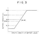
- FIG. 3 is a graph illustrating a relationship between a specific gravity of battery liquid and a capacity of a battery. As shown in this graph, the capacity of the battery is proportional to the specific gravity of the battery liquid between 0 (V) and the maximum capacity Bm (V). In the present embodiment, the specific gravity of the battery liquid is detected by the specific gravity meter to thereby detect the capacity of the battery 2 making use of the relationship therebetween in the FIG. 3 graph.
- the chopper circuit 67 outputs a DC current in a given period.
- a pulse signal having a predetermined pulse according to the control signal from the control means 66 is output.
- the control means 66 performs the control of the general operation of the excavator 1.
- the control means 66 has a voltage control portion 66a for controlling a voltage applied to the electric motor 3 according to the detected value of the battery capacity sensor 65.
- the voltage control portion 66a outputs a control signal to the chopper circuit 67 so that a pulse voltage having a duty ratio according to the detected voltage value is applied to the electric motor 3.
- a reference capacity Bs is previously set to a predetermined level lower than the maximum battery capacity Bm (V) of the battery 2.
- the value of the reference capacity Bs is stored in the voltage control portion 66a.
- a control signal is output to the chopper circuit 67 from the voltage control portion 66a so that a current continuously flows to the base of the transistor 63b whereby the transistor 63b assumes a state in which the switch is always turned on, and a predetermined voltage (B1 (V)) is applied to the electric motor 3 from the battery 2.
- a control signal is output to the chopper circuit 67 from the voltage control portion 66 so that a voltage Vd obtained by deducting a voltage value (k x (Bs - B2), where k is proportional constant (k > 1)) proportional to a difference between the reference capacity Bs and the detected capacity B2 from the reference capacity Bs is applied to the electric motor 3.
- This voltage control is carried out by converting an electromotive force of the battery 2 into a pulse voltage by the transistor 63b to make it into a predetermined duty ratio so that a mean voltage value is the deducted voltage Vd.
- a limit capacity BL of the battery 2 is previously input into the control means 66.
- a control signal is output to the switching control valve 56 from the voltage control portion 66.
- a supply of the pilot oil from the pilot pump 41 to the second operating means 5b is cutoff. That is, the proximal actuator 14a cannot be operated in the state where the detected capacity B of the battery 2 is at a level lower than the limit capacity BL.
- the hydraulic motor 12b can be driven to move the excavator 1 without wasting the less-remaining capacity of the battery 2. Thereby, it is possible to prevent the excavator from being disabled in the working site.
- the voltage control portion 66a When the detected capacity B is between the reference capacity Bs and the limit capacity BL, the voltage control portion 66a outputs a control signal to the chopper circuit 67 so that the duty ratio is calculated so that the detected capacity B2 is the deducted voltage Vd to obtain the duty ratio on the basis of a program stored in advance on the basis of the detected capacity B of the battery capacity sensor 65.
- the chopper circuit 67 intermittently outputs a signal for fulfilling the duty ratio to the base of the transistor 63b.
- the transistor 63b performs on-off operation at a predetermined timing. Thereby, a current is intermittently supplied to the electric motor 3 in a state where the duty ratio is fulfilled, and a pulse voltage which is the deducted voltage Vd on the average is applied to the electric motor 3.
- the hydraulic motor 12b and the proximal actuator 14a can be operated in a state where the capacity of the battery 2 is not rapidly lowered by the first operating means 5a and the second operating means 5b.
- FIG. 4 is a flow chart showing one embodiment of the control by the control circuit 64; and FIG. 5 shows waveforms illustrating a relationship between the detected capacity B of the battery capacity sensor 65 and a voltage applied to the electric motor 3.
- A shows the state where the detected capacity B1 is at a level higher than the reference capacity Bs, and
- B shows the state where the detected capacity B1 is at a level lower than the reference capacity Bs.
- Step S1 the specific gravity of battery liquid is detected by the battery capacity sensor 65, and in Step S2, the detected result is input into the control means 66, where the value of the specific gravity is converted into the voltage value (detected capacity B). Then, in Step S3, the voltage control portion 66a determines whether or not the detected capacity B is at a level lower than the preset reference capacity Bs.
- Step S1 When the detected capacity B is "NO" which is a level higher than the reference capacity Bs, the procedure is returned to Step S1. In this state, a voltage corresponding to the detected capacity B1 at a level higher than the reference capacity Bs is continuously applied to the electric motor 3, as shown in FIG. 5 (A), and the hydraulic pump 4 is operated by the drive of the electric motor 3 so that in the excavator 1, the hydraulic motor 12b and the proximal actuator 14a are placed in a normal operatable condition capable of being operated by the operation of the operating means 5.
- Step S4 when the detected capacity B is "YES" which is a level lower than the reference capacity Bs, Step S4 is executed. That is, in Step S4, a value obtained by multiplying a difference between the reference capacity Bs and the detected capacity B2 by a predetermined constant k (k > 1) is deducted from the reference capacity Bs (Bs - k ⁇ (Bs - B2)), and a pulse voltage of the resultant calculated value, that is, the deducted voltage Vd is applied to the electric motor 3. This pulse voltage is obtained by the control of the duty ratio so that an average value is the deducted voltage Vd, as shown in FIG. 5 (B). In Step S5, whether or not the detected capacity B2 is at a level lower than the limit capacity BL is determined.
- Step S6 the switching control valve 56 is closed by the control signal from the control means 66 whereby even if the second operating means 5b is operated, the pilot oil is not supplied to the second directional control valve 55b. For this reason, the proximal actuator 14a assumes a state where the operation thereof is locked.
- the capacity of the battery 2 is always detected by the battery capacity sensor 65 during the operation of the excavator 1, and when the detected capacity B is at a level lower than the preset reference capacity Bs, a pulse voltage at a potential lower than the reference capacity Bs is applied to the electric motor 3, thus suppressing the power consumption of the battery 2 accordingly and enabling the extension of the used-up of the battery.
- the transistor 63b is turned on and off by the duty ratio according to the operating amount of the operating lever 51 by the operation of the voltage control portion 66a and the chopper circuit 67. Therefore, for example, as compared with an arrangement wherein a voltage from the battery 2 is supplied to the electric motor 3 through a variable resistor, it is possible to extend the service life of the battery 2 by a portion involved no power consumption by the resistor to enable the operation of the excavator 1 for a long period of time.
- the detected capacity B2 is at a level lower than the limit capacity BL, even if the second operating means 5b is operated to the operating position by opening and closing the control valve 56, the proximal actuator 14a will not be operated. For this reason, it is possible to effectively use the less-remaining capacity of the battery 2 only for the operation of the excavator 1. It is possible to positively prevent the excavator 1 from being not moved in the working site in the midst of work.
Landscapes
- Engineering & Computer Science (AREA)
- Mining & Mineral Resources (AREA)
- Civil Engineering (AREA)
- General Engineering & Computer Science (AREA)
- Structural Engineering (AREA)
- Physics & Mathematics (AREA)
- General Physics & Mathematics (AREA)
- Operation Control Of Excavators (AREA)
Applications Claiming Priority (2)
| Application Number | Priority Date | Filing Date | Title |
|---|---|---|---|
| JP152703/96 | 1996-06-13 | ||
| JP8152703A JPH101978A (ja) | 1996-06-13 | 1996-06-13 | バッテリ駆動の作業機械 |
Publications (1)
| Publication Number | Publication Date |
|---|---|
| EP0812965A1 true EP0812965A1 (fr) | 1997-12-17 |
Family
ID=15546307
Family Applications (1)
| Application Number | Title | Priority Date | Filing Date |
|---|---|---|---|
| EP97303914A Withdrawn EP0812965A1 (fr) | 1996-06-13 | 1997-06-06 | Machine de chantier entraînée par batterie |
Country Status (4)
| Country | Link |
|---|---|
| US (1) | US5991677A (fr) |
| EP (1) | EP0812965A1 (fr) |
| JP (1) | JPH101978A (fr) |
| KR (1) | KR100206511B1 (fr) |
Cited By (3)
| Publication number | Priority date | Publication date | Assignee | Title |
|---|---|---|---|---|
| EP1126085A1 (fr) * | 1999-03-31 | 2001-08-22 | Kobelco Construction Machinery Co., Ltd. | Machine a travailler pourvue d'un condensateur |
| CN106347118A (zh) * | 2016-10-12 | 2017-01-25 | 阿特拉斯科普柯(南京)建筑矿山设备有限公司 | 地下铲运机传动系统 |
| WO2021046736A1 (fr) * | 2019-09-11 | 2021-03-18 | 徐州徐工挖掘机械有限公司 | Système et procédé de commande de treuil hydraulique |
Families Citing this family (14)
| Publication number | Priority date | Publication date | Assignee | Title |
|---|---|---|---|---|
| DE19710363A1 (de) * | 1997-03-13 | 1998-09-24 | Bosch Gmbh Robert | Schaltungsanordnung zum Versorgen eines Verbrauchers mit elektrischer Energie |
| JP3877901B2 (ja) * | 1999-03-31 | 2007-02-07 | コベルコ建機株式会社 | ショベル |
| JP4133752B2 (ja) * | 2003-11-11 | 2008-08-13 | 本田技研工業株式会社 | 作業機 |
| US7950481B2 (en) * | 2005-09-29 | 2011-05-31 | Caterpillar Inc. | Electric powertrain for machine |
| US7658250B2 (en) * | 2006-09-29 | 2010-02-09 | Caterpillar Inc. | Energy storage and recovery for a tracked machine |
| JP2008121659A (ja) * | 2006-10-20 | 2008-05-29 | Kobelco Contstruction Machinery Ltd | ハイブリッド作業機械 |
| JP5113603B2 (ja) * | 2008-04-18 | 2013-01-09 | 日立建機株式会社 | 電動式作業機械 |
| US8857635B2 (en) * | 2010-12-22 | 2014-10-14 | Terex Cranes Germany Gmbh | Crane and method for operating a crane using recovery of energy from crane operations as a secondary energy source |
| US8751084B2 (en) | 2012-05-08 | 2014-06-10 | Curtis Instruments, Inc. | Vehicle component recognition and adjustment for energy efficiency |
| CN102817394B (zh) * | 2012-09-07 | 2014-10-01 | 三一重机有限公司 | 一种挖掘机液压泵控制系统及方法及挖掘机 |
| US9484602B1 (en) | 2013-08-22 | 2016-11-01 | OSC Manufacturing & Equipment Services, Inc. | Light tower having a battery housing |
| JP6502179B2 (ja) * | 2015-05-29 | 2019-04-17 | 古河ユニック株式会社 | 移動式クレーンの作動制御装置 |
| US10749224B2 (en) | 2015-08-17 | 2020-08-18 | OSC Manufacturing & Equipment Services, Inc. | Rechargeable battery power system having a battery with multiple uses |
| CN112709283B (zh) * | 2020-12-29 | 2022-01-07 | 徐工集团工程机械股份有限公司科技分公司 | 一种纯电动装载机液压控制系统及控制方法 |
Citations (10)
| Publication number | Priority date | Publication date | Assignee | Title |
|---|---|---|---|---|
| FR2297183A1 (fr) * | 1975-01-08 | 1976-08-06 | Fenwick Manutention Ste Indle | Indicateur de decharge d'une batterie d'accumulateurs |
| US4066936A (en) * | 1974-06-10 | 1978-01-03 | Toshio Hirota | Hybrid battery electric drive |
| US4210855A (en) * | 1977-06-10 | 1980-07-01 | Robert Bosch Gmbh | Apparatus for regulating the current drawn from an electric battery |
| DE3339890A1 (de) * | 1983-11-04 | 1985-05-23 | Jungheinrich Unternehmensverwaltung Kg, 2000 Hamburg | Elektrik-anlage eines batteriegetriebenen fahrzeugs |
| DE3339884A1 (de) * | 1983-11-04 | 1985-05-23 | Jungheinrich Unternehmensverwaltung Kg, 2000 Hamburg | Elektrik-anlage eines batteriegetriebenen fahrzeugs |
| US4723107A (en) * | 1986-01-28 | 1988-02-02 | Steinbock Gmbh | Hydraulic lifting mechanism |
| DE4331721A1 (de) * | 1992-09-18 | 1994-03-31 | Hitachi Ltd | Bremssteuervorrichtung für ein Elektromotorfahrzeug |
| US5367455A (en) * | 1991-08-02 | 1994-11-22 | Honda Giken Kogyo Kabushiki Kaisha | Running performance control apparatus and method for an electric vehicle |
| US5416702A (en) * | 1991-05-22 | 1995-05-16 | Honda Giken Kogyo Kabushiki Kaisha | Vehicle electrical-load limiting apparatus |
| JPH08219117A (ja) * | 1995-02-08 | 1996-08-27 | Mitsubishi Agricult Mach Co Ltd | 作業用機械の制御装置 |
Family Cites Families (4)
| Publication number | Priority date | Publication date | Assignee | Title |
|---|---|---|---|---|
| JP3335677B2 (ja) * | 1992-09-22 | 2002-10-21 | 株式会社小松製作所 | 建設機械の走行操作装置 |
| DE69420491T2 (de) * | 1993-02-09 | 1999-12-23 | Hitachi Construction Machinery | Hydraulische steuerungsvorrichtung für baumaschinen |
| US5845223A (en) * | 1993-07-02 | 1998-12-01 | Samsung Heavy Industry Co., Ltd. | Apparatus and method for controlling actuators of hydraulic construction equipment |
| JPH10152865A (ja) * | 1996-11-22 | 1998-06-09 | Yutani Heavy Ind Ltd | バッテリ駆動の作業機械 |
-
1996
- 1996-06-13 JP JP8152703A patent/JPH101978A/ja active Pending
-
1997
- 1997-06-04 US US08/869,138 patent/US5991677A/en not_active Expired - Lifetime
- 1997-06-06 EP EP97303914A patent/EP0812965A1/fr not_active Withdrawn
- 1997-06-13 KR KR1019970024460A patent/KR100206511B1/ko not_active IP Right Cessation
Patent Citations (10)
| Publication number | Priority date | Publication date | Assignee | Title |
|---|---|---|---|---|
| US4066936A (en) * | 1974-06-10 | 1978-01-03 | Toshio Hirota | Hybrid battery electric drive |
| FR2297183A1 (fr) * | 1975-01-08 | 1976-08-06 | Fenwick Manutention Ste Indle | Indicateur de decharge d'une batterie d'accumulateurs |
| US4210855A (en) * | 1977-06-10 | 1980-07-01 | Robert Bosch Gmbh | Apparatus for regulating the current drawn from an electric battery |
| DE3339890A1 (de) * | 1983-11-04 | 1985-05-23 | Jungheinrich Unternehmensverwaltung Kg, 2000 Hamburg | Elektrik-anlage eines batteriegetriebenen fahrzeugs |
| DE3339884A1 (de) * | 1983-11-04 | 1985-05-23 | Jungheinrich Unternehmensverwaltung Kg, 2000 Hamburg | Elektrik-anlage eines batteriegetriebenen fahrzeugs |
| US4723107A (en) * | 1986-01-28 | 1988-02-02 | Steinbock Gmbh | Hydraulic lifting mechanism |
| US5416702A (en) * | 1991-05-22 | 1995-05-16 | Honda Giken Kogyo Kabushiki Kaisha | Vehicle electrical-load limiting apparatus |
| US5367455A (en) * | 1991-08-02 | 1994-11-22 | Honda Giken Kogyo Kabushiki Kaisha | Running performance control apparatus and method for an electric vehicle |
| DE4331721A1 (de) * | 1992-09-18 | 1994-03-31 | Hitachi Ltd | Bremssteuervorrichtung für ein Elektromotorfahrzeug |
| JPH08219117A (ja) * | 1995-02-08 | 1996-08-27 | Mitsubishi Agricult Mach Co Ltd | 作業用機械の制御装置 |
Non-Patent Citations (1)
| Title |
|---|
| PATENT ABSTRACTS OF JAPAN vol. 096, no. 012 26 December 1996 (1996-12-26) * |
Cited By (5)
| Publication number | Priority date | Publication date | Assignee | Title |
|---|---|---|---|---|
| EP1126085A1 (fr) * | 1999-03-31 | 2001-08-22 | Kobelco Construction Machinery Co., Ltd. | Machine a travailler pourvue d'un condensateur |
| EP1126085A4 (fr) * | 1999-03-31 | 2003-01-02 | Kobelco Constr Machinery Ltd | Machine a travailler pourvue d'un condensateur |
| US6635973B1 (en) | 1999-03-31 | 2003-10-21 | Kobelco Construction Machinery Co., Ltd. | Capacitor-equipped working machine |
| CN106347118A (zh) * | 2016-10-12 | 2017-01-25 | 阿特拉斯科普柯(南京)建筑矿山设备有限公司 | 地下铲运机传动系统 |
| WO2021046736A1 (fr) * | 2019-09-11 | 2021-03-18 | 徐州徐工挖掘机械有限公司 | Système et procédé de commande de treuil hydraulique |
Also Published As
| Publication number | Publication date |
|---|---|
| KR100206511B1 (ko) | 1999-07-01 |
| US5991677A (en) | 1999-11-23 |
| JPH101978A (ja) | 1998-01-06 |
| KR980002498A (ko) | 1998-03-30 |
Similar Documents
| Publication | Publication Date | Title |
|---|---|---|
| EP0812965A1 (fr) | Machine de chantier entraînée par batterie | |
| JP3941951B2 (ja) | ハイブリッド作業機械の駆動制御装置 | |
| US6635973B1 (en) | Capacitor-equipped working machine | |
| JP2568507Y2 (ja) | 建設機械の微操作モード制御装置 | |
| KR101714948B1 (ko) | 건설 기계 | |
| KR940009269B1 (ko) | 산업차량의 제어장치 | |
| GB2431248A (en) | Rotation control device, rotation control method, and construction machine | |
| EP0814206B1 (fr) | Machine de chantier entraínée par batterie | |
| US5913811A (en) | Battery-driven hydraulic excavator | |
| JP2009256988A (ja) | 電動式作業機械 | |
| JP2011157751A (ja) | 油圧作業機 | |
| JP2005086892A (ja) | ハイブリッド作業機械の駆動制御装置 | |
| JP3443253B2 (ja) | バッテリ駆動作業機械の制御装置および制御方法 | |
| JP4063742B2 (ja) | ハイブリッド作業機械の駆動制御装置 | |
| JP3708224B2 (ja) | バッテリ駆動の作業機械 | |
| CN113454297B (zh) | 作业机械 | |
| JPH10159133A (ja) | バッテリ駆動作業機械の制御装置および制御方法 | |
| JP3686476B2 (ja) | バッテリ駆動の作業機械 | |
| JPH1096250A (ja) | バッテリ駆動の作業機械 | |
| JP2002322926A (ja) | ハイブリッド建設機械のエンジン制御装置 | |
| WO2022153735A1 (fr) | Engin de chantier | |
| JPH10110451A (ja) | バッテリ駆動の作業機械 | |
| JPH08219117A (ja) | 作業用機械の制御装置 | |
| JP3155158B2 (ja) | バッテリ式フォークリフト | |
| JP3540929B2 (ja) | 電気車の回生制御方法 |
Legal Events
| Date | Code | Title | Description |
|---|---|---|---|
| PUAI | Public reference made under article 153(3) epc to a published international application that has entered the european phase |
Free format text: ORIGINAL CODE: 0009012 |
|
| 17P | Request for examination filed |
Effective date: 19970702 |
|
| AK | Designated contracting states |
Kind code of ref document: A1 Designated state(s): DE FR GB IT |
|
| AKX | Designation fees paid |
Free format text: DE FR GB IT |
|
| RBV | Designated contracting states (corrected) |
Designated state(s): DE FR GB IT |
|
| 17Q | First examination report despatched |
Effective date: 20031209 |
|
| STAA | Information on the status of an ep patent application or granted ep patent |
Free format text: STATUS: THE APPLICATION IS DEEMED TO BE WITHDRAWN |
|
| 18D | Application deemed to be withdrawn |
Effective date: 20040622 |