EP1125740B1 - Verfahren und Anordnung zum Reinigen von Leitwalzen einer Rollendruckmachine - Google Patents
Verfahren und Anordnung zum Reinigen von Leitwalzen einer Rollendruckmachine Download PDFInfo
- Publication number
- EP1125740B1 EP1125740B1 EP00102950A EP00102950A EP1125740B1 EP 1125740 B1 EP1125740 B1 EP 1125740B1 EP 00102950 A EP00102950 A EP 00102950A EP 00102950 A EP00102950 A EP 00102950A EP 1125740 B1 EP1125740 B1 EP 1125740B1
- Authority
- EP
- European Patent Office
- Prior art keywords
- web
- container
- printing material
- cleaning fluid
- sealing lip
- Prior art date
- Legal status (The legal status is an assumption and is not a legal conclusion. Google has not performed a legal analysis and makes no representation as to the accuracy of the status listed.)
- Expired - Lifetime
Links
- 238000004140 cleaning Methods 0.000 title claims abstract description 133
- 238000000034 method Methods 0.000 title claims abstract description 23
- 238000007639 printing Methods 0.000 claims abstract description 88
- 238000007789 sealing Methods 0.000 claims abstract description 78
- 239000000463 material Substances 0.000 claims abstract description 74
- 239000012530 fluid Substances 0.000 claims description 43
- 238000011109 contamination Methods 0.000 claims description 5
- 230000001154 acute effect Effects 0.000 claims description 3
- 238000004891 communication Methods 0.000 claims 2
- 230000001105 regulatory effect Effects 0.000 claims 1
- 239000007788 liquid Substances 0.000 abstract description 92
- 239000000758 substrate Substances 0.000 description 27
- 239000007921 spray Substances 0.000 description 10
- 230000000694 effects Effects 0.000 description 5
- 238000012546 transfer Methods 0.000 description 5
- 239000000428 dust Substances 0.000 description 4
- 230000015572 biosynthetic process Effects 0.000 description 3
- 239000006260 foam Substances 0.000 description 3
- 238000004519 manufacturing process Methods 0.000 description 3
- 230000008901 benefit Effects 0.000 description 2
- 230000008859 change Effects 0.000 description 2
- 239000000356 contaminant Substances 0.000 description 2
- 239000000835 fiber Substances 0.000 description 2
- 238000012423 maintenance Methods 0.000 description 2
- -1 polyoxymethylene Polymers 0.000 description 2
- 230000008569 process Effects 0.000 description 2
- 238000005507 spraying Methods 0.000 description 2
- 230000032258 transport Effects 0.000 description 2
- 238000005406 washing Methods 0.000 description 2
- 238000012935 Averaging Methods 0.000 description 1
- 229930040373 Paraformaldehyde Natural products 0.000 description 1
- 239000004698 Polyethylene Substances 0.000 description 1
- 238000010521 absorption reaction Methods 0.000 description 1
- 230000009471 action Effects 0.000 description 1
- 239000000853 adhesive Substances 0.000 description 1
- 230000001070 adhesive effect Effects 0.000 description 1
- 230000033228 biological regulation Effects 0.000 description 1
- 239000012459 cleaning agent Substances 0.000 description 1
- 230000007423 decrease Effects 0.000 description 1
- 230000001419 dependent effect Effects 0.000 description 1
- 238000011161 development Methods 0.000 description 1
- 230000018109 developmental process Effects 0.000 description 1
- 238000005516 engineering process Methods 0.000 description 1
- 238000007654 immersion Methods 0.000 description 1
- 239000012535 impurity Substances 0.000 description 1
- 238000005259 measurement Methods 0.000 description 1
- 239000003595 mist Substances 0.000 description 1
- 238000007645 offset printing Methods 0.000 description 1
- 238000004091 panning Methods 0.000 description 1
- 229920000573 polyethylene Polymers 0.000 description 1
- 229920006324 polyoxymethylene Polymers 0.000 description 1
- 239000007787 solid Substances 0.000 description 1
- 238000003860 storage Methods 0.000 description 1
- 239000004753 textile Substances 0.000 description 1
Images

Classifications
-
- B—PERFORMING OPERATIONS; TRANSPORTING
- B41—PRINTING; LINING MACHINES; TYPEWRITERS; STAMPS
- B41F—PRINTING MACHINES OR PRESSES
- B41F35/00—Cleaning arrangements or devices
- B41F35/007—Cleaning arrangements or devices for supports of workpieces
-
- B—PERFORMING OPERATIONS; TRANSPORTING
- B41—PRINTING; LINING MACHINES; TYPEWRITERS; STAMPS
- B41P—INDEXING SCHEME RELATING TO PRINTING, LINING MACHINES, TYPEWRITERS, AND TO STAMPS
- B41P2235/00—Cleaning
- B41P2235/50—Selection of materials or products for cleaning
Definitions
- the invention relates to a method for cleaning guide rollers of a web printing machine with a printing material web guided over a number of guide rollers according to the preamble of appended claim 1 and a corresponding one Arrangement according to the preamble of appended claim 10.
- Automated washing machines have been known for a long time. Such includes, for example a brush roller that wets the cleaning liquid with cleaning liquids Cylinder is rotated and there are contaminants such as ink residues, torn out paper fibers and paper dust, loosens and takes off.
- the guide rollers generally have very little space available stands and the number of guide rollers compared to that directly at the print cylinders involved is very high, it is generally not practical for everyone Guide roller to assign one of the known automated washing devices. Instead the guide rollers are traditionally cleaned by hand such that an operator sprays the printing material web with cleaning fluid and then slowly run the printing material web through the printing press lets, then when the moistened portion of the substrate over a guide roller runs, this guide roller brakes by hand. This will make a Slip generated between the guide roller surface and the substrate web; the cleaning agents brought up to the guide roller surface with the printing material web loosens the dirt and the printing material web wipes the relevant one Guide roller clean.
- the US Pat. No. 4,781,116 shows a device which has been common for a long time Automated procedure for printing presses with paper webs:
- the ones there The arrangement shown comprises an arranged in front of the guide rollers to be cleaned Application device, the cleaning liquid from a by means of an immersion roller Trough removed and similar to the printing process of a transfer roller gives up, which in turn is in contact with the paper web and the carried Transfers cleaning fluid to this.
- the paper web transports the applied one Cleaning liquid to the guide rollers to be cleaned, which in turn with Drive motors are provided, which generate a slip between the paper web and the guide roller surface to the corresponding guide rollers be coupled.
- the transfer roller not only cleaning liquid on the paper web, but also contaminants, such as paper dust in particular, from the paper web transfers back into the cleaning liquid container. It therefore forms over time in the cleaning liquid container a sump that regularly from Hand must be eliminated.
- US 5,080,015 discloses an arrangement for cleaning guide rolls a web press based on the same traditional principle, whereby the guide rollers are simply braked to generate the necessary slip and the application of the cleaning liquid to the paper web by means of spray nozzles he follows.
- the spray nozzles avoid the above disadvantage of the stand the technology according to US 4,781,116, but problems also arise here: a Spraying process always produces a certain spray mist, which is in terms of the required Occupational safety is undesirable.
- Occupational safety is undesirable.
- the possible inhalation only one aspect of spray from workers because, for example, in newspaper printing cleaning fluids usually used from an oil fraction exist, the spray deposit on stairs and scaffolding is below Occupational safety aspects highly problematic.
- the Spraying the optimal amount of cleaning liquids: Too much cleaning liquid leads to dripping of the same; too little cleaning fluid to poor cleaning results.
- the invention is based on the object a method based on the principle just outlined and a corresponding one Propose an arrangement for cleaning guide rollers of a web printing press, reliable, safe and low-maintenance automated cleaning the guide rollers enables.
- the inventive method and the operation of the corresponding arrangement are based on the known principle, cleaning liquid on the Apply printing substrate bahri and from the printing substrate web to the ones to be cleaned Guide rollers to be transported, the guide rollers to be cleaned at running printing material web are braked or accelerated to one Slip between the substrate and the surface of the respective guide roller generate so that the pollution of the guide roller surface by the Cleaning liquid loaded and / or dry printing material web wiped off and is lifted off.
- the cleaning result depends on the substrate used optimal when the slip between the guide roller and the substrate creates while the moistened web is in contact with the guide roller.
- the cleaning liquid according to the invention is now neither with a transfer roller still applied to the substrate with spray nozzles, but the printing material web is used in this way to apply the cleaning liquid of a container with cleaning liquid that they are in direct contact with the receives cleaning liquid in the container and thereby cleaning liquid receives.
- the application of cleaning fluid on the substrate is optimal if it contains the cleaning liquid records itself by - depending on the type of printing material used - itself soaked with cleaning liquid or due to adhesive forces and surface tension effects a film of liquid adhering to its surface entraining.
- the loading of the printing material web with cleaning liquid corresponds so by itself the maximum or almost maximum absorption capacity of the printing material web, without it being necessary to intervene regularly. Also a change the substrate does not require any changes when applying the cleaning fluid.
- the environment of the application device remains Application of cleaning liquid completely unaffected; in particular there is no undesirable one Spray.
- the printing material web can, for example, in the cleaning liquid in the container immersed or passed along the surface thereof, the container in the simplest case is designed as an upwardly open tub. Especially is preferred in the context of the invention, however, if the cleaning liquid via an elastically deformable sealing lip on the container to the printing material web arrives.
- a sealing lip can in particular on the side Containers are arranged so that the level of the cleaning liquid is scarce lies over the outer edge of the sealing lip, so that the printing material web, which the sealing lip is guided past, the liquid standing above the sealing lip with laminar flow behavior. The sealing lip ensures ensuring that the cleaning liquid reaches the web without leakage.
- a dynamic is formed Balance that keeps the level constant within very narrow limits, without sensors for level measurement and to provide separate control loops.
- the cleaning liquid flowing out of the container via the overflow is preferred collected in a collecting container, the first container being cleaning fluid is supplied directly to this collecting container. This is how it is formed a cycle for the cleaning liquid, which only through the substrate Cleaning liquid is removed.
- the amount of cleaning fluid removed is added to this circuit, for example from a storage tank, the collecting container advantageously serving as a buffer.
- the sealing lip which is preferably present is expediently at an acute angle adjusted to the printing material web, so that the one above the sealing lip Volume of cleaning liquid to the outside, for contact with the printing material web provided edge decreases. For one thing, this is a possible spilling of the cleaning liquid advantageous, and on the other the printing material web then hits the sealing lip very flat, what that Risk of web break greatly reduced.
- the container with cleaning liquid present according to the invention must be normal ongoing production of the printing machine removed from the printing material web so as not to disturb the pressure. Conversely, the container must be carried out of the method according to the invention are placed on the printing material web.
- a container with a sealing lip preferably by pivoting the Container around an axis running parallel to the substrate web plane. The container becomes to position the sealing lip on the substrate tipped and tipped away again to end the liquid application. This is not only efficient and space-saving, but also enables in particular a very quick interruption of the liquid application.
- Such a pivotable container with a sealing lip is particularly preferred in its geometric proportions so matched that the cleaning liquid when parked, clearly below the outer edge of the sealing lip stands. If the container is pivoted towards the printing material web so that the sealing lip Contact with the printing material web, the level of the cleaning liquid lies then close to the outer edge of the sealing lip, but not yet about that. First a further swiveling of the container towards the printing material web, which is possible due to the elastic deformability of the sealing lip, leads to that the level of cleaning fluid is above the edge of the sealing lip comes, so that the cleaning liquid in direct contact with the substrate device and this is taken to the guide rollers. When parking the sealing lip of the printing material web has the opposite effect. Because of this geometry there is no point in the cleaning liquid could be spilled - not even in an "emergency stop".
- a catch lip can be arranged below the sealing lip, which make contact with the substrate at the same time or slightly earlier than the sealing lip receives and is connected to the collecting container. About from The sealing lip dripping down cleaning liquid is then from the Caught the lip and into the container, i.e. back into the circuit, directed.
- the catch lip can be designed so that they on the one hand at a lower limit of the Housing and on the other hand abuts the sealing lip, which causes the housing is closed.
- the housing therefore does not only contain the container with sealing lip, but also the collecting container for the cleaning liquid.
- Sealing lip with a toothed edge can be used: Because the sealing lip is due to their elastic deformability on contact with the printing material web in the direction the individual teeth act from their movement, that is to say they deform a toothed edge of the sealing lip as an obstacle for the cleaning liquid, so that this only in the spaces between the teeth to the substrate can reach, but not on the teeth themselves. Depending on the ratio between the width of the teeth and the width of the interdental spaces is therefore only achieved a partial coverage of the printing material web with cleaning liquid, which limits the cleaning fluid application.
- the teeth can be shaped very differently, for example with triangular or rectangular teeth, but also with rounded teeth or as a wavy line.
- Another particularly advantageous option is the application of cleaning fluid below the maximum possible intake quantity of the printing material web, consists in a clocked mode of operation of the application device: if the liquid application to the substrate is activated in quick succession and is deactivated, the amount of liquid applied on average is dependent on the cycle times and cycle intervals - adjustable.
- the particular advantage here is that, in contrast to the toothed sealing lip, no structural changes must be done on the application device, but that a corresponding Regulation of the timing is sufficient.
- the timing is particularly easy to carry out, if a swiveling container with sealing lip is used; because then a small, clocked tilting movement of the container is enough to achieve the desired one To achieve effect for the liquid application.
- the sealing lip can face at least part of the surface facing the printing substrate Form the container wall, but it is necessary that the container front is provided with elastically deformable or foldable walls around the end faces to keep the container tight.
- the cleaning liquid is preferably fed into the container at the same time in different places distributed over its volume, on the one hand a vortex formation within the container and on the other hand a gradient of the Avoid levels. Furthermore, the cleaning liquid is preferably below of the normal level, so as not to affect the surface of the liquid to let and in particular to avoid wave formation. The easiest this is achieved by using a radial opening Pipe element is arranged inside the container. For example a pipe or hose with a variety of distributed along its length Holes.
- the application device can comprise two containers, which are located on both sides of the printing material web to be ordered. It is particularly advantageous here if the two Containers are arranged opposite each other, since then the two sealing lips apply the necessary counterforce to each other. Because if that alone Web tension the counterforce must apply, on the one hand, the contact force of the Sealing lip not well defined and secondly the risk of a web break many times larger.
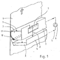
- FIG. 1 shows a schematic view of an application device according to the invention, the side of a paper web 1 running vertically upwards is.
- the application device itself consists of a container 2 open at the top with cleaning liquid 3 and a collecting container 4 arranged underneath, from which the cleaning liquid 3 via a feed 5 and a pump 6 in the container 2 is conveyed.
- Excess cleaning liquid 3 in the container 2 flows over the overflow 7 along the arrow 8 into the collecting container 4, so that the level 9 of the cleaning liquid 3 in the container 2 regardless of the through the amount of paper 1 removed remains constant.
- the overflow 7 and thus the level 9 is adjustable in height.
- the to the paper web 1 facing wall of the container 2 is by an elastically deformable Sealing lip 10 formed, for example, from polyoxymethylene or Polyethylene is made of what materials are relatively hard and rub-resistant, but still are springy.
- the sealing lip 10 is, as can be seen well, in a point Angle on the paper web 1 to make the smoothest possible contact.
- the outer edge 11 intended for contact with the paper web 1 the sealing lip 10 is a few millimeters below the level 9 of the cleaning liquid 3, so that the paper web 1 is in direct contact with that in the container 2
- Cleaning liquid 3 stands and about adhesion forces and surface tension effects laminar just takes as much cleaning liquid 3 as corresponds to the optimal loading of the paper web 1. From the paper web 1 amount of cleaning liquid 3 removed from the container 2 (not here shown) added to the system of container 2 and container 4, so that the collecting container 4 also serves as a buffer for the cleaning liquid circuit.
- the inventive method Application device for performing the guide roller cleaning to the To start paper web 1 and after finishing cleaning again from this shutdown: It is conceivable, for example, a linear, lateral on and off movement perform.
- the container 2 can be parallel to the Paper web level 1 extending axis can be pivoted. Panning too only the sealing lip 10 is conceivable.
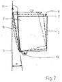
- FIG. 2 now shows schematically what is particularly preferred in the context of the invention Swiveling the entire container 2 about an axis 12 around the application device to the paper web 1: With solid lines the container 2 shown in the parked position. The level 9 of the cleaning liquid is here 3 clearly below the outer edge 11 of the sealing lip 10. A pivoting around the axis 12 leaves the sealing lip 10 at an acute angle ⁇ run onto paper web 1. The time at which the edge 11 of the sealing lip 10 just gets contact with the paper web 1, is with openwork Lines shown. In this phase, level 9 is still close below the edge 11 of the sealing lip 10; a liquid application on the paper web 1 does not take place yet.
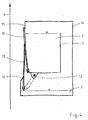
- FIG 3 shows a similar schematic representation as Figure 2, with the application device is employed on the paper web 1 and with a sealing lip 10 and an additional catch lip 13 is provided.
- the catch lip 13 becomes common with the container 2 pivoted about the axis 12 and already receives contact with the paper web 1 before the sealing lip 10 activates the liquid application. Should therefore be caused by wave formation in container 2 or by other irregularities Cleaning liquid 3 pass over the edge 11 of the sealing lip 10, before this gets in contact with the paper web 1, this liquid of the collecting lip 13 caught and passed into the collecting container 4.
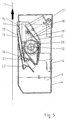
- FIG. 4 shows a representation similar to FIG. 3, with the application device parked from the paper web 1 and to protect the cleaning liquid 3 from Contamination is provided with a housing 14.
- the housing 14 has one upper limit 15 and a lower limit 16, which cooperate with the sealing lip 10 and the collecting lip 13 a complete closure of the Ensure housing 14 as soon as the container 2 is pivoted back completely is.
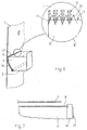
- Figure 5 shows a true-to-scale, schematic section through an application device according to the invention, wherein the container 2 with a sealing lip 10 and a collecting lip 13 is provided and a housing 14 with an integrated collecting container 4 is provided for the cleaning liquid 3.
- the housing 14 is with provided with a removable cover 17 for maintenance purposes and is complete pivoted back container 2 through the sealing lip 10, the catch lip 13 and the upper limit 15 and the lower limit 16 are sealed.
- the container 2 is so pivoted about the axis 12 that when swiveling out first the catch lip 13, and then the sealing lip 10 Get in touch with paper web 1.
- the swivel movement is by means of a Piston-cylinder unit 18, which is preferably operated with compressed air, wherein a lever 19 the linear movement of the piston-cylinder unit 18 in implements a rotary movement.
- the lever 19 engages one through the container 2 running pipe 20, which runs longitudinally through the entire container 2 and with a plurality of holes distributed over its length.
- This Tube 20 thus not only acts as a journal for the pivoting movement, but also at the same time as a line element for the supply of cleaning liquid 3 in the container 2.
- both the Sealing lip 10 and the collecting lip 13 are easily exchangeable in brackets 21 and 22 sit. This is advantageous because the paper web 1 has relatively high abrasive properties shows.
- Figure 6 shows one possibility, such as by means of a toothed edge 11 of the sealing lip 10 a lower amount of cleaning liquid can be achieved on the paper web 1 is:
- the level 9 of the cleaning liquid 3 set so that in the projection onto the paper web 1 in Area of the teeth 23 is, so that only in the spaces between the individual teeth 24 contact between the cleaning liquid 3 and the Paper web 1 and therefore only a partial application of a cleaning liquid film 25 can be done.
- FIG. 7 shows the frontal boundary in a schematic plan view a container 2, as it is also shown in Figure 1: Since the paper web 1 pointing wall of the container 2 is formed by the sealing lip 10, and this deforms elastically when the container 2 is placed against the paper web 1, may the connection of the sealing lip 10 to the end wall of the container 2nd don't be rigid. According to the embodiment shown here, the end wall from an easily deformable foam seal 26 and a solid Support plate 27. The sealing lip 10 can therefore move relative to the support plate 27, while the resilient foam seal 26, the front tightness the container 3 guaranteed.
- the method according to the invention and the corresponding arrangement are not only for web presses with paper webs suitable, but can also be used for other web-shaped substrates, such as textiles. Also a horizontally arranged one Sealing lip or a path deviating from the illustrations - with or without a sealing lip - is encompassed by the inventive teaching. Likewise are different forms of the container according to the invention are conceivable, which may differ significantly from the shapes shown in the figures.
Landscapes
- Inking, Control Or Cleaning Of Printing Machines (AREA)
- Preliminary Treatment Of Fibers (AREA)
- Advancing Webs (AREA)
- Cleaning In General (AREA)
Description
- Figur 1
- einen schematischen, perspektivischen Teilschnitt einer Auftragsvorrichtung nach der Erfindung;
- Figur 2
- eine schematische Schnittdarstellung eines Behälters für Reinigungsflüssigkeit;
- Figur 3
- eine Darstellung wie Figur 2, jedoch eines anderen Ausführungsbeispiels;
- Figur 4
- eine Darstellung wie Figur 3, jedoch eines weiteren Ausführungsbeispiels;
- Figur 5
- eine maßstabsgetreue Schnittdarstellung einer erfindungsgemäßen Auftragsvorrichtung
- Figur 6
- eine schematische Darstellung einer weiteren Ausführungsform einer Auftragsvorrichtung, mit Detailvergrößerung;
- Figur 7
- eine schematische Draufsicht auf den Randbereich einer erfindungsgemäßen Auftragsvorrichtung.
- 1
- Papierbahn
- 2
- Behälter
- 3
- Reinigungsflüssigkeit
- 4
- Auffangbehälter
- 5
- Zuführung
- 6
- Pumpe
- 7
- Überlauf
- 8
- Pfeil
- 9
- Pegel
- 10
- Abdichtlippe
- 11
- Kante
- 12
- Achse
- 13
- Auffanglippe
- 14
- Gehäuse
- 15
- Begrenzung (obere)
- 16
- Begrenzung (untere)
- 17
- Deckel (von 14)
- 18
- Kolben-Zylinder-Einheit
- 19
- Hebel
- 20
- Rohr
- 21
- Halterung (von 10)
- 22
- Halterung (von 13)
- 23
- Zahnung
- 24
- Zähne
- 25
- Reinigungsflüssigkeitsfilm
- 26
- Schaumstoffdichtung
- 27
- Stützblech
- α
- Winkel
- X
- Detail
Claims (23)
- Verfahren zum Reinigen von Leitwalzen einer Rollendruckmaschine mit einer über eine Anzahl von Leitwalzen geführten Bedruckstoffbahn, wobei Reinigungsflüssigkeit auf die Bedruckstoffbahn aufgebracht und von der Bedruckstoffbahn zu den zu reinigenden Leitwalzen transportiert wird, und wobei die zu reinigenden Leitwalzen bei laufender Bedruckstoffbahn abgebremst oder beschleunigt werden, um einen Schlupf zwischen der Bedruckstoffbahn und der Oberfläche der jeweiligen Leitwalze zu erzeugen, wodurch die Verschmutzung der Leitwalzenoberfläche durch die mit Reinigungsflüssigkeit beladene und/oder trockene Bedruckstoffbahn abgewischt und abgehoben wird,
dadurch gekennzeichnet, daß die Bedruckstoffbahn zum Aufbringen der Reinigungsflüssigkeit derart entlang eines Behälters mit Reinigungsflüssigkeit geführt wird, daß sie direkten Kontakt mit der im Behälter befindlichen Reinigungsflüssigkeit erhält und dadurch Reinigungsflüssigkeit aufnimmt. - Verfahren nach Anspruch 1,
dadurch gekennzeichnet, daß der Pegel der Reinigungsflüssigkeit im Behälter mittels eines Überlaufs und einer überproportional hohen Zuführung von Reinigungsflüssigkeit in den Behälter konstant gehalten wird. - Verfahren nach einem der Ansprüche 1 oder 2,
dadurch gekennzeichnet, daß die Reinigungsflüssigkeit über eine am Behälter angeordnete, elastisch verformbare Abdichtlippe zur Bedruckstoffbahn gelangt. - Verfahren nach Anspruch 3,
dadurch gekennzeichnet, daß die Abdichtlippe in spitzem Winkel an die Bedruckstoffbahn angestellt wird. - Verfahren nach einem der Ansprüche 3 oder 4,
dadurch gekennzeichnet, daß die Abdichtlippe durch Verschwenken des Behälters um eine parallel zur Bedruckstoffbahnebene verlaufende Achse an die Bedruckstoffbahn angestellt wird. - Verfahren nach Anspruch 5,
dadurch gekennzeichnet, daß der Behälter bei gerade eben an die Bedruckstoffbahn angestellter Abdichtlippe unter elastischer Verformung derselben weiter zur Bedruckstoffbahn hin verschwenkt wird, bis der Pegel der Reinigungsflüssigkeit im Behälter über der an der Bedruckstoffbahn anliegenden Kante der Abdichtlippe steht, während der Pegel der Reinigungsflüssigkeit unterhalb dieser Kante steht, wenn der Behälter so verschwenkt wird, daß die Abdichtlippe die Bedruckstoffbahn nicht berührt. - Verfahren nach einem der Ansprüche 1 bis 6,
dadurch gekennzeichnet, daß die Reinigungsflüssigkeit dem Behälter gleichzeitig an verschiedenen, über dessen Volumen verteilten und unterhalb des üblichen Pegels liegenden Stellen zugeführt wird. - Verfahren nach einem der Ansprüche 1 bis 7,
dadurch gekennzeichnet, daß zwei Behälter mit Reinigungsflüssigkeit verwendet werden, die beidseits der Bedruckstoffbahn einander gegenüberliegen. - Verfahren nach einem der Ansprüche 1 bis 8,
dadurch gekennzeichnet, daß das Aufbringen der Reinigungsflüssigkeit auf die Bedruckstoffbahn getaktet erfolgt, um die im Mittel aufgebrachte Menge an Reinigungsflüssigkeit zu regeln. - Anordnung zum Reinigen von Leitwalzen einer Rollendruckmaschine mit einer über eine Anzahl von Leitwalzen geführten Bedruckstoffbahn, insbesondere zur Durchführung des Verfahrens nach einem der Ansprüche 1 bis 9, umfassend eine vor den zu reinigenden Leitwalzen angeordnete Auftragsvorrichtung zum Aufbringen von Reinigungsflüssigkeit auf die Bedruckstoffbahn sowie für jede zu reinigende Leitwalze eine Brems- oder Antriebsvorrichtung zur Erzeugung eines Schlupfs zwischen der laufenden Bedruckstoffbahn und der Oberfläche der jeweiligen Leitwalze, um die Verschmutzung der Leitwalzenoberfläche durch die mit Reinigungsflüssigkeit beladene und/oder trockene Bedruckstoffbahn abzuwischen und abzuheben,
dadurch gekennzeichnet, daß die Auftragsvorrichtung einen Behälter (2) mit Reinigungsflüssigkeit (3) umfaßt und daß die Bedruckstoffbahn (1) derart entlang des Behälters (2) geführt ist, daß sie direkten Kontakt mit der im Behälter (2) befindlichen Reinigungsflüssigkeit (3) erhält und dadurch Reinigungsflüssigkeit (3) aufnimmt. - Anordnung nach Anspruch 10,
dadurch gekennzeichnet, daß der Behälter (2) mit einer Zuführung (5) für Reinigungsflüssigkeit (3) und einem Überlauf (7) zur Konstanthaltung des Pegels (9) der Reinigungsflüssigkeit (3) versehen ist. - Anordnung nach Anspruch 11,
dadurch gekennzeichnet, daß der Behälter (2) über den Überlauf (7) und die Zuführung (5) mit einem Auffangbehälter (4) in Verbindung steht. - Anordnung nach einem der Ansprüche 10 bis 12,
dadurch gekennzeichnet, daß der Behälter (2) mit einer für den Kontakt mit der Bedruckstoffbahn (1) vorgesehenen, elastisch verformbaren Abdichtlippe (10) versehen ist. - Anordnung nach Anspruch 13,
dadurch gekennzeichnet, daß die Abdichtlippe (10) durch Verschwenken des Behälters (2) um eine parallel zur Bedruckstoffbahnebene verlaufende Achse (12) an die Bedruckstoffbahn (1) anstellbar ist. - Anordnung nach Anspruch 14,
dadurch gekennzeichnet, daß der Behälter (2) bei gerade eben an die Bedruckstoffbahn (1) angestellter Abdichtlippe (10) unter elastischer Verformung derselben weiter zur Bedruckstoffbahn (1) hin verschwenkbar ist, bis der Pegel (9) der Reinigungsflüssigkeit (3) im Behälter (2) über der an der Bedruckstoffbahn (1) anliegenden Kante (11) der Abdichtlippe (10) steht, wobei der Pegel (9) der Reinigungsflüssigkeit (3) so eingestellt ist, daß er bei abgestellter Dichtlippe (10) unterhalb dieser Kante (11) steht, so lange die Abdichtlippe (10) keinen Kontakt zur Bedruckstoffbahn (1) hat. - Anordnung nach Anspruch 15,
dadurch gekennzeichnet, daß der verschwenkbare Behälter (2) derart in ein feststehendes Gehäuse (14) integriert ist, daß die Abdichtlippe (10) bei zurückgeschwenktem Behälter (2) an einer oberen Begrenzung (15) des Gehäuses (14) anliegt und das Gehäuse (14) hierdurch verschließt. - Anordnung nach Anspruch 12 und einem der Ansprüche 13 bis 16,
dadurch gekennzeichnet, daß unterhalb der Abdichtlippe (10) eine für einen weiteren Kontakt mit der Bedruckstoffbahn (1) vorgesehene, mit dem Auffangbehälter (4) in Verbindung stehende Auffanglippe (13) angeordnet ist. - Anordnung nach den Ansprüchen 16 und 17,
dadurch gekennzeichnet, daß die Auffanglippe (13) bei zurückgeschwenktem Behälter (2) zum Verschließen des Gehäuses (14) einerseits an einer unteren Begrenzung (16) des Gehäuses (14) und andererseits an der Abdichtlippe (10) anliegt. - Anordnung nach einem der Ansprüche 13 bis 18,
dadurch gekennzeichnet, daß die Abdichtlippe (10) eine gerade oder eine gezahnte Kante (11) für den Kontakt mit der Bedruckstoffbahn (1) aufweist. - Anordnung nach einem der Ansprüche 13 bis 19,
dadurch gekennzeichnet, daß die Abdichtlippe (10) zumindest einen Teil der zur Bedruckstoffbahn (1) weisenden Behälterwand bildet und der Behälter (2) stirnseitig mit elastisch verformbaren oder faltbaren Wänden (26, 27) versehen ist. - Anordnung nach einem der Ansprüche 10 bis 20,
dadurch gekennzeichnet, daß der Behälter (2) ein mit radialen Öffnungen versehenes Leitungselement (20) zur Zuführung von Reinigungsflüssigkeit (3) beinhaltet. - Anordnung nach einem der Ansprüche 10 bis 21,
dadurch gekennzeichnet, daß die Auftragsvorrichtung zum Regeln der auf die Bedruckstoffbahn (1) aufgebrachten Reinigungsflüssigkeit (3) derart ausgebildet ist, daß der direkte Kontakt der Bedruckstoffbahn (1) mit der im Behälter (2) befindlichen Reinigungsflüssigkeit (3) getaktet erfolgen kann. - Anordnung nach einem der Ansprüche 10 bis 22,
dadurch gekennzeichnet, daß die Auftragsvorrichtung zwei Behälter (2) umfaßt, die beidseits der Bedruckstoffbahn (1) einander gegenüberliegend angeordnet sind.
Priority Applications (4)
| Application Number | Priority Date | Filing Date | Title |
|---|---|---|---|
| EP00102950A EP1125740B1 (de) | 2000-02-14 | 2000-02-14 | Verfahren und Anordnung zum Reinigen von Leitwalzen einer Rollendruckmachine |
| AT00102950T ATE250503T1 (de) | 2000-02-14 | 2000-02-14 | Verfahren und anordnung zum reinigen von leitwalzen einer rollendruckmachine |
| DE50003826T DE50003826D1 (de) | 2000-02-14 | 2000-02-14 | Verfahren und Anordnung zum Reinigen von Leitwalzen einer Rollendruckmachine |
| US09/783,500 US6401619B2 (en) | 2000-02-14 | 2001-02-14 | Method and device for cleaning the guide rollers of a web printing press |
Applications Claiming Priority (1)
| Application Number | Priority Date | Filing Date | Title |
|---|---|---|---|
| EP00102950A EP1125740B1 (de) | 2000-02-14 | 2000-02-14 | Verfahren und Anordnung zum Reinigen von Leitwalzen einer Rollendruckmachine |
Publications (2)
| Publication Number | Publication Date |
|---|---|
| EP1125740A1 EP1125740A1 (de) | 2001-08-22 |
| EP1125740B1 true EP1125740B1 (de) | 2003-09-24 |
Family
ID=8167841
Family Applications (1)
| Application Number | Title | Priority Date | Filing Date |
|---|---|---|---|
| EP00102950A Expired - Lifetime EP1125740B1 (de) | 2000-02-14 | 2000-02-14 | Verfahren und Anordnung zum Reinigen von Leitwalzen einer Rollendruckmachine |
Country Status (4)
| Country | Link |
|---|---|
| US (1) | US6401619B2 (de) |
| EP (1) | EP1125740B1 (de) |
| AT (1) | ATE250503T1 (de) |
| DE (1) | DE50003826D1 (de) |
Cited By (1)
| Publication number | Priority date | Publication date | Assignee | Title |
|---|---|---|---|---|
| EP2674747B1 (de) | 2012-06-13 | 2019-02-20 | BST eltromat International GmbH | Verfahren und vorrichtung für die farbmessung an einem druckbild auf einer laufenden materialbahn |
Families Citing this family (4)
| Publication number | Priority date | Publication date | Assignee | Title |
|---|---|---|---|---|
| DE10238949B3 (de) * | 2002-08-24 | 2004-02-12 | Voith Paper Patent Gmbh | Verfahren zum Reinigen einer Walze in einem Kalander |
| FR2867172B1 (fr) * | 2004-03-03 | 2006-05-26 | Snecma Propulsion Solide | Dispositif de recentrage de tissu |
| WO2010042123A1 (en) * | 2008-10-10 | 2010-04-15 | Hewlett-Packard Development Company, L.P. | Automatic cleaning air idler |
| NL2016719B1 (nl) * | 2016-05-02 | 2017-11-10 | Boers Holding B V | Werkwijze voor het reinigen van een bedrukte baan flexibel materiaal, alsmede een inrichting daarvoor. |
Family Cites Families (12)
| Publication number | Priority date | Publication date | Assignee | Title |
|---|---|---|---|---|
| DE2203973A1 (de) * | 1972-01-28 | 1973-08-09 | Erich Pagendarm | Verfahren und vorrichtung zum befeuchten einer bahn |
| JPS5616424B2 (de) * | 1973-06-15 | 1981-04-16 | ||
| AT374379B (de) * | 1982-03-29 | 1984-04-10 | Zimmer Johannes | Vorrichtung zum gleichmaessigen auftragen bestimmbarer fluessigkeitsmengen |
| AU579278B2 (en) | 1986-04-28 | 1988-11-17 | Nikka Kabushiki Kaisha | Washing method and apparatus for guide rollers of rotary press |
| DE3736397A1 (de) * | 1987-10-28 | 1989-05-11 | Spiess Gmbh G | Gummituchwaschvorrichtung |
| US4930415A (en) * | 1988-02-10 | 1990-06-05 | Baldwin-Japan Limited | Automatic web guide roller cleaning device |
| JP2572366B2 (ja) * | 1988-05-24 | 1997-01-16 | 株式会社東京機械製作所 | 輪転印刷機 |
| US5080015A (en) | 1989-10-10 | 1992-01-14 | Jimek International Ab | Method and arrangement for cleaning guide rollers |
| JPH03177257A (ja) * | 1989-12-04 | 1991-08-01 | Tokyo Kikai Seisakusho Ltd | ウェブ料紙案内装置 |
| CN1096942C (zh) * | 1995-05-01 | 2002-12-25 | 鲍德温·格拉菲克系统有限公司 | 就地浸渍和印刷机上浸渍清洁系统及其使用方法 |
| JPH08300623A (ja) * | 1995-05-10 | 1996-11-19 | Nikka Kk | 加湿ローラ |
| DE19721213A1 (de) * | 1997-05-21 | 1998-12-10 | Koenig & Bauer Albert Ag | Verfahren und Einrichtung zum Reinigen von Papierleitwalzen |
-
2000
- 2000-02-14 AT AT00102950T patent/ATE250503T1/de not_active IP Right Cessation
- 2000-02-14 DE DE50003826T patent/DE50003826D1/de not_active Expired - Fee Related
- 2000-02-14 EP EP00102950A patent/EP1125740B1/de not_active Expired - Lifetime
-
2001
- 2001-02-14 US US09/783,500 patent/US6401619B2/en not_active Expired - Fee Related
Cited By (1)
| Publication number | Priority date | Publication date | Assignee | Title |
|---|---|---|---|---|
| EP2674747B1 (de) | 2012-06-13 | 2019-02-20 | BST eltromat International GmbH | Verfahren und vorrichtung für die farbmessung an einem druckbild auf einer laufenden materialbahn |
Also Published As
| Publication number | Publication date |
|---|---|
| ATE250503T1 (de) | 2003-10-15 |
| US6401619B2 (en) | 2002-06-11 |
| DE50003826D1 (de) | 2003-10-30 |
| EP1125740A1 (de) | 2001-08-22 |
| US20010029860A1 (en) | 2001-10-18 |
Similar Documents
| Publication | Publication Date | Title |
|---|---|---|
| EP0533035B1 (de) | Vorrichtung zum Auftragen von Streichfarbe auf eine Faserstoffbahn | |
| AT393246B (de) | Auftragsvorrichtung zum aufbringen fliessfaehiger medien auf ebene flaechen, bahnen, walzen od. dgl. | |
| DE4244058A1 (de) | ||
| DE4126888A1 (de) | Bahnreinigungsanlage zur reinigung einer zu bedruckenden bahn | |
| EP1544353B1 (de) | Vorhang-Auftragsvorrichtung | |
| EP1125740B1 (de) | Verfahren und Anordnung zum Reinigen von Leitwalzen einer Rollendruckmachine | |
| EP2277630B1 (de) | Vorrichtung zum Beschichten einer durchlaufenden Bahn | |
| DE69909357T2 (de) | Druckmaschine für Bogen aus Wellpappe und Verfahren zum Reinigen des Farbkastens der Maschine | |
| DE19702605A1 (de) | Vorrichtung und Verfahren zum direkten oder indirekten Auftragen eines flüssigen oder pastösen Mediums auf eine laufende Materialbahn | |
| EP0901839B1 (de) | Vorrichtung zum Auftragen von Flüssigkeiten auf ein Substrat | |
| DE4221527C2 (de) | Vorrichtung zum Reinigen eines Walzenspaltes in Rotationsdruckmaschinen | |
| EP1198643A1 (de) | Auftragsvorrichtung | |
| DE102013213059A1 (de) | Vorrichtung und Verfahren zum Aufbringen und Dosieren von Reinigungsflüssigkeit | |
| EP2397328A1 (de) | Traversierende Farbkastenreinigung | |
| EP1621257B1 (de) | Vorrichtung zum Auftrag von Abschnitten von Flotte auf eine laufende Warenbahn | |
| DE19929843A1 (de) | Oberflächen-Behandlungsvorrichtung | |
| WO2005059250A1 (de) | Vorhangauftragswerk | |
| DE4327421C2 (de) | Vorrichtung zum Einfärben von strukturierten, flächigen Teilen | |
| EP0738594A1 (de) | Verfahren und Vorrichtung zum Auftragen von Flüssigkeiten auf Folienbahnen, insbesondere von Farbdrucken | |
| AT402207B (de) | Verfahren zum wahlweisen oder kombinierbaren bearbeiten von bahnförmigem material | |
| EP0949380A2 (de) | Vorrichtung zum direkten oder indirekten, ein- oder beidseitigen Auftragen eines flüssigen oder pastösen Mediums auf eine laufende Oberfläche | |
| DE10256326A1 (de) | Verfahren zur Reinigung der Siebschablone einer Siebdruckeinrichtung und Siebdruckmaschine zur Durchführung des Verfahrens | |
| DE10112756A1 (de) | Filmfarbwerk in einer Druckmaschine und verfahren zu dessen Reinigung | |
| EP1118708B1 (de) | Auftragsvorrichtung | |
| DE10003161A1 (de) | Vorrichtung und Verfahren zum Erzeugen eines mit Reinigungsflüssigkeit befeuchteten Reinigungsvlieses |
Legal Events
| Date | Code | Title | Description |
|---|---|---|---|
| PUAI | Public reference made under article 153(3) epc to a published international application that has entered the european phase |
Free format text: ORIGINAL CODE: 0009012 |
|
| AK | Designated contracting states |
Kind code of ref document: A1 Designated state(s): AT BE CH CY DE DK ES FI FR GB GR IE IT LI LU MC NL PT SE |
|
| AX | Request for extension of the european patent |
Free format text: AL;LT;LV;MK;RO;SI |
|
| 17P | Request for examination filed |
Effective date: 20020207 |
|
| AKX | Designation fees paid |
Free format text: AT BE CH CY DE DK ES FI FR GB GR IE IT LI LU MC NL PT SE |
|
| GRAH | Despatch of communication of intention to grant a patent |
Free format text: ORIGINAL CODE: EPIDOS IGRA |
|
| GRAS | Grant fee paid |
Free format text: ORIGINAL CODE: EPIDOSNIGR3 |
|
| GRAA | (expected) grant |
Free format text: ORIGINAL CODE: 0009210 |
|
| AK | Designated contracting states |
Kind code of ref document: B1 Designated state(s): AT BE CH CY DE DK ES FI FR GB GR IE IT LI LU MC NL PT SE |
|
| PG25 | Lapsed in a contracting state [announced via postgrant information from national office to epo] |
Ref country code: NL Free format text: LAPSE BECAUSE OF FAILURE TO SUBMIT A TRANSLATION OF THE DESCRIPTION OR TO PAY THE FEE WITHIN THE PRESCRIBED TIME-LIMIT Effective date: 20030924 Ref country code: FI Free format text: LAPSE BECAUSE OF FAILURE TO SUBMIT A TRANSLATION OF THE DESCRIPTION OR TO PAY THE FEE WITHIN THE PRESCRIBED TIME-LIMIT Effective date: 20030924 Ref country code: CY Free format text: LAPSE BECAUSE OF FAILURE TO SUBMIT A TRANSLATION OF THE DESCRIPTION OR TO PAY THE FEE WITHIN THE PRESCRIBED TIME-LIMIT Effective date: 20030924 Ref country code: IE Free format text: LAPSE BECAUSE OF FAILURE TO SUBMIT A TRANSLATION OF THE DESCRIPTION OR TO PAY THE FEE WITHIN THE PRESCRIBED TIME-LIMIT Effective date: 20030924 |
|
| REG | Reference to a national code |
Ref country code: GB Ref legal event code: FG4D Free format text: NOT ENGLISH |
|
| REG | Reference to a national code |
Ref country code: CH Ref legal event code: EP |
|
| REG | Reference to a national code |
Ref country code: IE Ref legal event code: FG4D Free format text: GERMAN |
|
| REF | Corresponds to: |
Ref document number: 50003826 Country of ref document: DE Date of ref document: 20031030 Kind code of ref document: P |
|
| REG | Reference to a national code |
Ref country code: CH Ref legal event code: NV Representative=s name: PATMED AG |
|
| PG25 | Lapsed in a contracting state [announced via postgrant information from national office to epo] |
Ref country code: DK Free format text: LAPSE BECAUSE OF FAILURE TO SUBMIT A TRANSLATION OF THE DESCRIPTION OR TO PAY THE FEE WITHIN THE PRESCRIBED TIME-LIMIT Effective date: 20031224 Ref country code: GR Free format text: LAPSE BECAUSE OF FAILURE TO SUBMIT A TRANSLATION OF THE DESCRIPTION OR TO PAY THE FEE WITHIN THE PRESCRIBED TIME-LIMIT Effective date: 20031224 |
|
| PG25 | Lapsed in a contracting state [announced via postgrant information from national office to epo] |
Ref country code: ES Free format text: LAPSE BECAUSE OF FAILURE TO SUBMIT A TRANSLATION OF THE DESCRIPTION OR TO PAY THE FEE WITHIN THE PRESCRIBED TIME-LIMIT Effective date: 20040104 |
|
| REG | Reference to a national code |
Ref country code: SE Ref legal event code: TRGR |
|
| PG25 | Lapsed in a contracting state [announced via postgrant information from national office to epo] |
Ref country code: LU Free format text: LAPSE BECAUSE OF NON-PAYMENT OF DUE FEES Effective date: 20040214 Ref country code: AT Free format text: LAPSE BECAUSE OF NON-PAYMENT OF DUE FEES Effective date: 20040214 |
|
| PG25 | Lapsed in a contracting state [announced via postgrant information from national office to epo] |
Ref country code: MC Free format text: LAPSE BECAUSE OF NON-PAYMENT OF DUE FEES Effective date: 20040228 Ref country code: BE Free format text: LAPSE BECAUSE OF NON-PAYMENT OF DUE FEES Effective date: 20040228 |
|
| NLV1 | Nl: lapsed or annulled due to failure to fulfill the requirements of art. 29p and 29m of the patents act | ||
| GBT | Gb: translation of ep patent filed (gb section 77(6)(a)/1977) |
Effective date: 20040210 |
|
| REG | Reference to a national code |
Ref country code: IE Ref legal event code: FD4D |
|
| ET | Fr: translation filed | ||
| PLBE | No opposition filed within time limit |
Free format text: ORIGINAL CODE: 0009261 |
|
| STAA | Information on the status of an ep patent application or granted ep patent |
Free format text: STATUS: NO OPPOSITION FILED WITHIN TIME LIMIT |
|
| BERE | Be: lapsed |
Owner name: *OXY-DRY MASCHINEN G.M.B.H. Effective date: 20040228 |
|
| 26N | No opposition filed |
Effective date: 20040625 |
|
| PGFP | Annual fee paid to national office [announced via postgrant information from national office to epo] |
Ref country code: CH Payment date: 20070222 Year of fee payment: 8 |
|
| PGFP | Annual fee paid to national office [announced via postgrant information from national office to epo] |
Ref country code: SE Payment date: 20070223 Year of fee payment: 8 |
|
| PG25 | Lapsed in a contracting state [announced via postgrant information from national office to epo] |
Ref country code: PT Free format text: LAPSE BECAUSE OF NON-PAYMENT OF DUE FEES Effective date: 20040224 |
|
| REG | Reference to a national code |
Ref country code: CH Ref legal event code: PL |
|
| EUG | Se: european patent has lapsed | ||
| PG25 | Lapsed in a contracting state [announced via postgrant information from national office to epo] |
Ref country code: LI Free format text: LAPSE BECAUSE OF NON-PAYMENT OF DUE FEES Effective date: 20080229 Ref country code: CH Free format text: LAPSE BECAUSE OF NON-PAYMENT OF DUE FEES Effective date: 20080229 |
|
| PG25 | Lapsed in a contracting state [announced via postgrant information from national office to epo] |
Ref country code: SE Free format text: LAPSE BECAUSE OF NON-PAYMENT OF DUE FEES Effective date: 20080215 |
|
| PGFP | Annual fee paid to national office [announced via postgrant information from national office to epo] |
Ref country code: DE Payment date: 20090225 Year of fee payment: 10 |
|
| PGFP | Annual fee paid to national office [announced via postgrant information from national office to epo] |
Ref country code: GB Payment date: 20090223 Year of fee payment: 10 |
|
| PGFP | Annual fee paid to national office [announced via postgrant information from national office to epo] |
Ref country code: IT Payment date: 20090326 Year of fee payment: 10 |
|
| PGFP | Annual fee paid to national office [announced via postgrant information from national office to epo] |
Ref country code: FR Payment date: 20090225 Year of fee payment: 10 |
|
| GBPC | Gb: european patent ceased through non-payment of renewal fee |
Effective date: 20100214 |
|
| REG | Reference to a national code |
Ref country code: FR Ref legal event code: ST Effective date: 20101029 |
|
| PG25 | Lapsed in a contracting state [announced via postgrant information from national office to epo] |
Ref country code: FR Free format text: LAPSE BECAUSE OF NON-PAYMENT OF DUE FEES Effective date: 20100301 |
|
| PG25 | Lapsed in a contracting state [announced via postgrant information from national office to epo] |
Ref country code: DE Free format text: LAPSE BECAUSE OF NON-PAYMENT OF DUE FEES Effective date: 20100901 |
|
| PG25 | Lapsed in a contracting state [announced via postgrant information from national office to epo] |
Ref country code: IT Free format text: LAPSE BECAUSE OF NON-PAYMENT OF DUE FEES Effective date: 20100214 Ref country code: GB Free format text: LAPSE BECAUSE OF NON-PAYMENT OF DUE FEES Effective date: 20100214 |