EP1125740B1 - Method and device for cleaning guide rollers in a web-fed rotary press - Google Patents
Method and device for cleaning guide rollers in a web-fed rotary press Download PDFInfo
- Publication number
- EP1125740B1 EP1125740B1 EP00102950A EP00102950A EP1125740B1 EP 1125740 B1 EP1125740 B1 EP 1125740B1 EP 00102950 A EP00102950 A EP 00102950A EP 00102950 A EP00102950 A EP 00102950A EP 1125740 B1 EP1125740 B1 EP 1125740B1
- Authority
- EP
- European Patent Office
- Prior art keywords
- web
- container
- printing material
- cleaning fluid
- sealing lip
- Prior art date
- Legal status (The legal status is an assumption and is not a legal conclusion. Google has not performed a legal analysis and makes no representation as to the accuracy of the status listed.)
- Expired - Lifetime
Links
Images

Classifications
-
- B—PERFORMING OPERATIONS; TRANSPORTING
- B41—PRINTING; LINING MACHINES; TYPEWRITERS; STAMPS
- B41F—PRINTING MACHINES OR PRESSES
- B41F35/00—Cleaning arrangements or devices
- B41F35/007—Cleaning arrangements or devices for supports of workpieces
-
- B—PERFORMING OPERATIONS; TRANSPORTING
- B41—PRINTING; LINING MACHINES; TYPEWRITERS; STAMPS
- B41P—INDEXING SCHEME RELATING TO PRINTING, LINING MACHINES, TYPEWRITERS, AND TO STAMPS
- B41P2235/00—Cleaning
- B41P2235/50—Selection of materials or products for cleaning
Definitions
- the invention relates to a method for cleaning guide rollers of a web printing machine with a printing material web guided over a number of guide rollers according to the preamble of appended claim 1 and a corresponding one Arrangement according to the preamble of appended claim 10.
- Automated washing machines have been known for a long time. Such includes, for example a brush roller that wets the cleaning liquid with cleaning liquids Cylinder is rotated and there are contaminants such as ink residues, torn out paper fibers and paper dust, loosens and takes off.
- the guide rollers generally have very little space available stands and the number of guide rollers compared to that directly at the print cylinders involved is very high, it is generally not practical for everyone Guide roller to assign one of the known automated washing devices. Instead the guide rollers are traditionally cleaned by hand such that an operator sprays the printing material web with cleaning fluid and then slowly run the printing material web through the printing press lets, then when the moistened portion of the substrate over a guide roller runs, this guide roller brakes by hand. This will make a Slip generated between the guide roller surface and the substrate web; the cleaning agents brought up to the guide roller surface with the printing material web loosens the dirt and the printing material web wipes the relevant one Guide roller clean.
- the US Pat. No. 4,781,116 shows a device which has been common for a long time Automated procedure for printing presses with paper webs:
- the ones there The arrangement shown comprises an arranged in front of the guide rollers to be cleaned Application device, the cleaning liquid from a by means of an immersion roller Trough removed and similar to the printing process of a transfer roller gives up, which in turn is in contact with the paper web and the carried Transfers cleaning fluid to this.
- the paper web transports the applied one Cleaning liquid to the guide rollers to be cleaned, which in turn with Drive motors are provided, which generate a slip between the paper web and the guide roller surface to the corresponding guide rollers be coupled.
- the transfer roller not only cleaning liquid on the paper web, but also contaminants, such as paper dust in particular, from the paper web transfers back into the cleaning liquid container. It therefore forms over time in the cleaning liquid container a sump that regularly from Hand must be eliminated.
- US 5,080,015 discloses an arrangement for cleaning guide rolls a web press based on the same traditional principle, whereby the guide rollers are simply braked to generate the necessary slip and the application of the cleaning liquid to the paper web by means of spray nozzles he follows.
- the spray nozzles avoid the above disadvantage of the stand the technology according to US 4,781,116, but problems also arise here: a Spraying process always produces a certain spray mist, which is in terms of the required Occupational safety is undesirable.
- Occupational safety is undesirable.
- the possible inhalation only one aspect of spray from workers because, for example, in newspaper printing cleaning fluids usually used from an oil fraction exist, the spray deposit on stairs and scaffolding is below Occupational safety aspects highly problematic.
- the Spraying the optimal amount of cleaning liquids: Too much cleaning liquid leads to dripping of the same; too little cleaning fluid to poor cleaning results.
- the invention is based on the object a method based on the principle just outlined and a corresponding one Propose an arrangement for cleaning guide rollers of a web printing press, reliable, safe and low-maintenance automated cleaning the guide rollers enables.
- the inventive method and the operation of the corresponding arrangement are based on the known principle, cleaning liquid on the Apply printing substrate bahri and from the printing substrate web to the ones to be cleaned Guide rollers to be transported, the guide rollers to be cleaned at running printing material web are braked or accelerated to one Slip between the substrate and the surface of the respective guide roller generate so that the pollution of the guide roller surface by the Cleaning liquid loaded and / or dry printing material web wiped off and is lifted off.
- the cleaning result depends on the substrate used optimal when the slip between the guide roller and the substrate creates while the moistened web is in contact with the guide roller.
- the cleaning liquid according to the invention is now neither with a transfer roller still applied to the substrate with spray nozzles, but the printing material web is used in this way to apply the cleaning liquid of a container with cleaning liquid that they are in direct contact with the receives cleaning liquid in the container and thereby cleaning liquid receives.
- the application of cleaning fluid on the substrate is optimal if it contains the cleaning liquid records itself by - depending on the type of printing material used - itself soaked with cleaning liquid or due to adhesive forces and surface tension effects a film of liquid adhering to its surface entraining.
- the loading of the printing material web with cleaning liquid corresponds so by itself the maximum or almost maximum absorption capacity of the printing material web, without it being necessary to intervene regularly. Also a change the substrate does not require any changes when applying the cleaning fluid.
- the environment of the application device remains Application of cleaning liquid completely unaffected; in particular there is no undesirable one Spray.
- the printing material web can, for example, in the cleaning liquid in the container immersed or passed along the surface thereof, the container in the simplest case is designed as an upwardly open tub. Especially is preferred in the context of the invention, however, if the cleaning liquid via an elastically deformable sealing lip on the container to the printing material web arrives.
- a sealing lip can in particular on the side Containers are arranged so that the level of the cleaning liquid is scarce lies over the outer edge of the sealing lip, so that the printing material web, which the sealing lip is guided past, the liquid standing above the sealing lip with laminar flow behavior. The sealing lip ensures ensuring that the cleaning liquid reaches the web without leakage.
- a dynamic is formed Balance that keeps the level constant within very narrow limits, without sensors for level measurement and to provide separate control loops.
- the cleaning liquid flowing out of the container via the overflow is preferred collected in a collecting container, the first container being cleaning fluid is supplied directly to this collecting container. This is how it is formed a cycle for the cleaning liquid, which only through the substrate Cleaning liquid is removed.
- the amount of cleaning fluid removed is added to this circuit, for example from a storage tank, the collecting container advantageously serving as a buffer.
- the sealing lip which is preferably present is expediently at an acute angle adjusted to the printing material web, so that the one above the sealing lip Volume of cleaning liquid to the outside, for contact with the printing material web provided edge decreases. For one thing, this is a possible spilling of the cleaning liquid advantageous, and on the other the printing material web then hits the sealing lip very flat, what that Risk of web break greatly reduced.
- the container with cleaning liquid present according to the invention must be normal ongoing production of the printing machine removed from the printing material web so as not to disturb the pressure. Conversely, the container must be carried out of the method according to the invention are placed on the printing material web.
- a container with a sealing lip preferably by pivoting the Container around an axis running parallel to the substrate web plane. The container becomes to position the sealing lip on the substrate tipped and tipped away again to end the liquid application. This is not only efficient and space-saving, but also enables in particular a very quick interruption of the liquid application.
- Such a pivotable container with a sealing lip is particularly preferred in its geometric proportions so matched that the cleaning liquid when parked, clearly below the outer edge of the sealing lip stands. If the container is pivoted towards the printing material web so that the sealing lip Contact with the printing material web, the level of the cleaning liquid lies then close to the outer edge of the sealing lip, but not yet about that. First a further swiveling of the container towards the printing material web, which is possible due to the elastic deformability of the sealing lip, leads to that the level of cleaning fluid is above the edge of the sealing lip comes, so that the cleaning liquid in direct contact with the substrate device and this is taken to the guide rollers. When parking the sealing lip of the printing material web has the opposite effect. Because of this geometry there is no point in the cleaning liquid could be spilled - not even in an "emergency stop".
- a catch lip can be arranged below the sealing lip, which make contact with the substrate at the same time or slightly earlier than the sealing lip receives and is connected to the collecting container. About from The sealing lip dripping down cleaning liquid is then from the Caught the lip and into the container, i.e. back into the circuit, directed.
- the catch lip can be designed so that they on the one hand at a lower limit of the Housing and on the other hand abuts the sealing lip, which causes the housing is closed.
- the housing therefore does not only contain the container with sealing lip, but also the collecting container for the cleaning liquid.
- Sealing lip with a toothed edge can be used: Because the sealing lip is due to their elastic deformability on contact with the printing material web in the direction the individual teeth act from their movement, that is to say they deform a toothed edge of the sealing lip as an obstacle for the cleaning liquid, so that this only in the spaces between the teeth to the substrate can reach, but not on the teeth themselves. Depending on the ratio between the width of the teeth and the width of the interdental spaces is therefore only achieved a partial coverage of the printing material web with cleaning liquid, which limits the cleaning fluid application.
- the teeth can be shaped very differently, for example with triangular or rectangular teeth, but also with rounded teeth or as a wavy line.
- Another particularly advantageous option is the application of cleaning fluid below the maximum possible intake quantity of the printing material web, consists in a clocked mode of operation of the application device: if the liquid application to the substrate is activated in quick succession and is deactivated, the amount of liquid applied on average is dependent on the cycle times and cycle intervals - adjustable.
- the particular advantage here is that, in contrast to the toothed sealing lip, no structural changes must be done on the application device, but that a corresponding Regulation of the timing is sufficient.
- the timing is particularly easy to carry out, if a swiveling container with sealing lip is used; because then a small, clocked tilting movement of the container is enough to achieve the desired one To achieve effect for the liquid application.
- the sealing lip can face at least part of the surface facing the printing substrate Form the container wall, but it is necessary that the container front is provided with elastically deformable or foldable walls around the end faces to keep the container tight.
- the cleaning liquid is preferably fed into the container at the same time in different places distributed over its volume, on the one hand a vortex formation within the container and on the other hand a gradient of the Avoid levels. Furthermore, the cleaning liquid is preferably below of the normal level, so as not to affect the surface of the liquid to let and in particular to avoid wave formation. The easiest this is achieved by using a radial opening Pipe element is arranged inside the container. For example a pipe or hose with a variety of distributed along its length Holes.
- the application device can comprise two containers, which are located on both sides of the printing material web to be ordered. It is particularly advantageous here if the two Containers are arranged opposite each other, since then the two sealing lips apply the necessary counterforce to each other. Because if that alone Web tension the counterforce must apply, on the one hand, the contact force of the Sealing lip not well defined and secondly the risk of a web break many times larger.
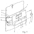
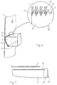
- FIG. 1 shows a schematic view of an application device according to the invention, the side of a paper web 1 running vertically upwards is.
- the application device itself consists of a container 2 open at the top with cleaning liquid 3 and a collecting container 4 arranged underneath, from which the cleaning liquid 3 via a feed 5 and a pump 6 in the container 2 is conveyed.
- Excess cleaning liquid 3 in the container 2 flows over the overflow 7 along the arrow 8 into the collecting container 4, so that the level 9 of the cleaning liquid 3 in the container 2 regardless of the through the amount of paper 1 removed remains constant.
- the overflow 7 and thus the level 9 is adjustable in height.
- the to the paper web 1 facing wall of the container 2 is by an elastically deformable Sealing lip 10 formed, for example, from polyoxymethylene or Polyethylene is made of what materials are relatively hard and rub-resistant, but still are springy.
- the sealing lip 10 is, as can be seen well, in a point Angle on the paper web 1 to make the smoothest possible contact.
- the outer edge 11 intended for contact with the paper web 1 the sealing lip 10 is a few millimeters below the level 9 of the cleaning liquid 3, so that the paper web 1 is in direct contact with that in the container 2
- Cleaning liquid 3 stands and about adhesion forces and surface tension effects laminar just takes as much cleaning liquid 3 as corresponds to the optimal loading of the paper web 1. From the paper web 1 amount of cleaning liquid 3 removed from the container 2 (not here shown) added to the system of container 2 and container 4, so that the collecting container 4 also serves as a buffer for the cleaning liquid circuit.
- the inventive method Application device for performing the guide roller cleaning to the To start paper web 1 and after finishing cleaning again from this shutdown: It is conceivable, for example, a linear, lateral on and off movement perform.
- the container 2 can be parallel to the Paper web level 1 extending axis can be pivoted. Panning too only the sealing lip 10 is conceivable.
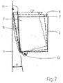
- FIG. 2 now shows schematically what is particularly preferred in the context of the invention Swiveling the entire container 2 about an axis 12 around the application device to the paper web 1: With solid lines the container 2 shown in the parked position. The level 9 of the cleaning liquid is here 3 clearly below the outer edge 11 of the sealing lip 10. A pivoting around the axis 12 leaves the sealing lip 10 at an acute angle ⁇ run onto paper web 1. The time at which the edge 11 of the sealing lip 10 just gets contact with the paper web 1, is with openwork Lines shown. In this phase, level 9 is still close below the edge 11 of the sealing lip 10; a liquid application on the paper web 1 does not take place yet.
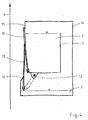
- FIG 3 shows a similar schematic representation as Figure 2, with the application device is employed on the paper web 1 and with a sealing lip 10 and an additional catch lip 13 is provided.
- the catch lip 13 becomes common with the container 2 pivoted about the axis 12 and already receives contact with the paper web 1 before the sealing lip 10 activates the liquid application. Should therefore be caused by wave formation in container 2 or by other irregularities Cleaning liquid 3 pass over the edge 11 of the sealing lip 10, before this gets in contact with the paper web 1, this liquid of the collecting lip 13 caught and passed into the collecting container 4.
- FIG. 4 shows a representation similar to FIG. 3, with the application device parked from the paper web 1 and to protect the cleaning liquid 3 from Contamination is provided with a housing 14.
- the housing 14 has one upper limit 15 and a lower limit 16, which cooperate with the sealing lip 10 and the collecting lip 13 a complete closure of the Ensure housing 14 as soon as the container 2 is pivoted back completely is.
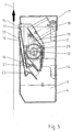
- Figure 5 shows a true-to-scale, schematic section through an application device according to the invention, wherein the container 2 with a sealing lip 10 and a collecting lip 13 is provided and a housing 14 with an integrated collecting container 4 is provided for the cleaning liquid 3.
- the housing 14 is with provided with a removable cover 17 for maintenance purposes and is complete pivoted back container 2 through the sealing lip 10, the catch lip 13 and the upper limit 15 and the lower limit 16 are sealed.
- the container 2 is so pivoted about the axis 12 that when swiveling out first the catch lip 13, and then the sealing lip 10 Get in touch with paper web 1.
- the swivel movement is by means of a Piston-cylinder unit 18, which is preferably operated with compressed air, wherein a lever 19 the linear movement of the piston-cylinder unit 18 in implements a rotary movement.
- the lever 19 engages one through the container 2 running pipe 20, which runs longitudinally through the entire container 2 and with a plurality of holes distributed over its length.
- This Tube 20 thus not only acts as a journal for the pivoting movement, but also at the same time as a line element for the supply of cleaning liquid 3 in the container 2.
- both the Sealing lip 10 and the collecting lip 13 are easily exchangeable in brackets 21 and 22 sit. This is advantageous because the paper web 1 has relatively high abrasive properties shows.
- Figure 6 shows one possibility, such as by means of a toothed edge 11 of the sealing lip 10 a lower amount of cleaning liquid can be achieved on the paper web 1 is:
- the level 9 of the cleaning liquid 3 set so that in the projection onto the paper web 1 in Area of the teeth 23 is, so that only in the spaces between the individual teeth 24 contact between the cleaning liquid 3 and the Paper web 1 and therefore only a partial application of a cleaning liquid film 25 can be done.
- FIG. 7 shows the frontal boundary in a schematic plan view a container 2, as it is also shown in Figure 1: Since the paper web 1 pointing wall of the container 2 is formed by the sealing lip 10, and this deforms elastically when the container 2 is placed against the paper web 1, may the connection of the sealing lip 10 to the end wall of the container 2nd don't be rigid. According to the embodiment shown here, the end wall from an easily deformable foam seal 26 and a solid Support plate 27. The sealing lip 10 can therefore move relative to the support plate 27, while the resilient foam seal 26, the front tightness the container 3 guaranteed.
- the method according to the invention and the corresponding arrangement are not only for web presses with paper webs suitable, but can also be used for other web-shaped substrates, such as textiles. Also a horizontally arranged one Sealing lip or a path deviating from the illustrations - with or without a sealing lip - is encompassed by the inventive teaching. Likewise are different forms of the container according to the invention are conceivable, which may differ significantly from the shapes shown in the figures.
Abstract
Description
Die Erfindung betrifft ein Verfahren zum Reinigen von Leitwalzen einer Rollendruckmaschine
mit einer über eine Anzahl von Leitwalzen geführten Bedruckstoffbahn
nach dem Oberbegriff des beigefügten Patentanspruchs 1 sowie eine entsprechende
Anordnung nach dem Oberbegriff des beigefügten Anspruchs 10.The invention relates to a method for cleaning guide rollers of a web printing machine
with a printing material web guided over a number of guide rollers
according to the preamble of appended
Zum Reinigen von Zylindern einer Rollendruckmaschine, die unmittelbar am Druck beteiligt sind, wie insbesondere Gummituchzylinder und Gegendruckzylinder, sind seit längerem automatisierte Waschgeräte bekannt. Ein solches umfaßt beispielsweise eine Bürstenwalze, die mit Reinigungsflüssigkeiten benetzt an den zu reinigenden Zylinder rotierend angestellt wird und dort Verunreinigungen, wie Druckfarbenreste, ausgerupfte Papierfasern und Papierstaub, löst und abhebt.For cleaning cylinders of a web-fed printing press that are directly on the press are involved, such as in particular blanket cylinders and impression cylinders Automated washing machines have been known for a long time. Such includes, for example a brush roller that wets the cleaning liquid with cleaning liquids Cylinder is rotated and there are contaminants such as ink residues, torn out paper fibers and paper dust, loosens and takes off.
Bei den heute üblichen Druckgeschwindigkeiten und den gestiegenen Anforderungen an die Qualität des Drucks ist es unabdingbar, daß auch diejenigen Leitwalzen, die mit der frisch bedruckten Bedruckstoffbahn in Kontakt kommen, regelmäβig von Verunreinigungen befreit werden, die sich insbesondere durch anhaftende Druckfarbenreste, Papierstaub und ausgerupfte Papierfasern auf den Leitwalzenoberflächen ansammeln und die Druckqualität kontinuierlich verschlechtern.With today's usual printing speeds and the increasing demands In terms of the quality of the print, it is essential that those guide rollers, that come into contact with the freshly printed substrate, regularly to be freed of impurities, in particular by adhering Ink residues, paper dust and torn paper fibers on the guide roller surfaces accumulate and the print quality deteriorate continuously.
Da bei den Leitwalzen jedoch in der Regel nur sehr wenig Platz zur Verfügung steht und die Anzahl der Leitwalzen im Vergleich zu den unmittelbar am Druck beteiligten Zylindern sehr hoch ist, ist es in aller Regel nicht praktikabel, jeder Leitwalze eine der bekannten automatisierten Waschgeräte zuzuordnen. Stattdessen wird die Reinigung der Leitwalzen traditionell von Hand durchgeführt, und zwar derart, daß eine Bedienperson die Bedruckstoffbahn mit Reinigungsflüssigkeit besprüht und die Bedruckstoffbahn dann langsam durch die Druckmaschine laufen läßt, wobei sie dann, wenn der befeuchtete Abschnitt der Bedruckstoffbahn über eine Leitwalze läuft, diese Leitwalze von Hand abbremst. Hierdurch wird ein Schlupf zwischen der Leitwalzenoberfläche und der Bedruckstoffbahn erzeugt; das mit der Bedruckstoffbahn an die Leitwalzenoberfläche herangeführte Reinigungsmittel löst die Verschmutzung und die Bedruckstoffbahn wischt die betreffende Leitwalze sauber.However, since the guide rollers generally have very little space available stands and the number of guide rollers compared to that directly at the print cylinders involved is very high, it is generally not practical for everyone Guide roller to assign one of the known automated washing devices. Instead the guide rollers are traditionally cleaned by hand such that an operator sprays the printing material web with cleaning fluid and then slowly run the printing material web through the printing press lets, then when the moistened portion of the substrate over a guide roller runs, this guide roller brakes by hand. This will make a Slip generated between the guide roller surface and the substrate web; the cleaning agents brought up to the guide roller surface with the printing material web loosens the dirt and the printing material web wipes the relevant one Guide roller clean.
Die Patentschrift US 4,781,116 zeigt eine Vorrichtung, die diese seit langem übliche Vorgehensweise bei Druckmaschinen mit Papierbahnen automatisiert: Die dort gezeigte Anordnung umfaßt eine vor den zu reinigenden Leitwalzen angeordnete Auftragsvorrichtung, die mittels einer Tauchwalze Reinigungsflüssigkeit aus einer Wanne entnimmt und ähnlich wie beim Druckvorgang einer Übertragungswalze aufgibt, welche ihrerseits mit der Papierbahn in Kontakt steht und die mitgeführte Reinigungsflüssigkeit auf diese überträgt. Die Papierbahn transportiert die aufgebrachte Reinigungsflüssigkeit zu den zu reinigenden Leitwalzen, die ihrerseits mit Antriebsmotoren versehen sind, welche zum Erzeugen eines Schlupfs zwischen der Papierbahn und der Leitwalzenoberfläche an die entsprechenden Leitwalzen gekoppelt werden. Nach diesem Stand der Technik ergibt sich allerdings das Problem, daß die Übertragungswalze nicht nur Reinigungsflüssigkeit auf die Papierbahn, sondern auch Verunreinigungen, wie insbesondere Papierstaub, von der Papierbahn zurück in den Reinigungsflüssigkeitsbehälter überträgt. Es bildet sich daher mit der Zeit im Reinigungsflüssigkeitsbehälter ein Sumpf, der regelmäßig von Hand beseitigt werden muß.The US Pat. No. 4,781,116 shows a device which has been common for a long time Automated procedure for printing presses with paper webs: The ones there The arrangement shown comprises an arranged in front of the guide rollers to be cleaned Application device, the cleaning liquid from a by means of an immersion roller Trough removed and similar to the printing process of a transfer roller gives up, which in turn is in contact with the paper web and the carried Transfers cleaning fluid to this. The paper web transports the applied one Cleaning liquid to the guide rollers to be cleaned, which in turn with Drive motors are provided, which generate a slip between the paper web and the guide roller surface to the corresponding guide rollers be coupled. According to this state of the art, however, the problem arises that the transfer roller not only cleaning liquid on the paper web, but also contaminants, such as paper dust in particular, from the paper web transfers back into the cleaning liquid container. It therefore forms over time in the cleaning liquid container a sump that regularly from Hand must be eliminated.
Die Patentschrift US 5,080,015 offenbart eine Anordnung zum Reinigen von Leitwalzen einer Rollendruckmaschine nach demselben traditionellen Prinzip, wobei die Leitwalzen zum Erzeugen des notwendigen Schlupfs einfach abgebremst werden und der Auftrag der Reinigungsflüssigkeit auf die Papierbahn mittels Sprühdüsen erfolgt. Die Sprühdüsen vermeiden den obengenannten Nachteil des Standes der Technik nach der US 4,781,116, jedoch ergeben sich auch hier Probleme: Ein Sprühvorgang erzeugt immer einen gewissen Sprühnebel, der hinsichtlich der erforderlichen Arbeitssicherheit unerwünscht ist. Hierbei ist das mögliche Einatmen von Sprühnebel durch Arbeitskräfte nur ein Aspekt; da die beispielsweise im Zeitungsdruck verwendeten Reinigungsflüssigkeiten in aller Regel aus einer Ölfraktion bestehen, ist auch der Sprühnebelniederschlag auf Treppen und Gerüsten unter Arbeitssicherheitsaspekten höchst problematisch. Hinzu kommt die Schwierigkeit, für jede verwendete Papierbahnqualität, die in rascher Folge wechseln kann, die optimale Menge an Reinigungsflüssigkeiten aufzusprühen: Zu viel Reinigungsflüssigkeit führt zum Heruntertropfen derselben; zu wenig Reinigungsflüssigkeit führt zu mangelhaften Reinigungsergebnissen.US 5,080,015 discloses an arrangement for cleaning guide rolls a web press based on the same traditional principle, whereby the guide rollers are simply braked to generate the necessary slip and the application of the cleaning liquid to the paper web by means of spray nozzles he follows. The spray nozzles avoid the above disadvantage of the stand the technology according to US 4,781,116, but problems also arise here: a Spraying process always produces a certain spray mist, which is in terms of the required Occupational safety is undesirable. Here is the possible inhalation only one aspect of spray from workers; because, for example, in newspaper printing cleaning fluids usually used from an oil fraction exist, the spray deposit on stairs and scaffolding is below Occupational safety aspects highly problematic. Add to that the difficulty for each paper web quality used, which can change in rapid succession, the Spraying the optimal amount of cleaning liquids: Too much cleaning liquid leads to dripping of the same; too little cleaning fluid to poor cleaning results.
Ausgehend von diesem Stand der Technik liegt der Erfindung die Aufgabe zugrunde, ein auf dem eben skizzierten Prinzip basierendes Verfahren und eine entsprechende Anordnung zum Reinigen von Leitwalzen einer Rollendruckmaschine vorzuschlagen, die eine zuverlässige, sichere und wartungsarme automatisierte Reinigung der Leitwalzen ermöglicht.Starting from this prior art, the invention is based on the object a method based on the principle just outlined and a corresponding one Propose an arrangement for cleaning guide rollers of a web printing press, reliable, safe and low-maintenance automated cleaning the guide rollers enables.
Diese Aufgabe ist durch ein Verfahren mit den Merkmalen des beigefügten Anspruchs
1 sowie durch eine Anordnung mit den Merkmalen des beigefügten Anspruchs
10 gelöst.This object is achieved by a method having the features of the appended
Vorteilhafte Weiterbildungen des Verfahrens ergeben sich aus den Ansprüchen 2
bis 9; bevorzugte Ausgestaltungen der erfindungsgemäßen Anordnung sind in den
Ansprüchen 11 bis 23 niedergelegt.Advantageous further developments of the method result from
Das erfindungsgemäße Verfahren und die Arbeitsweise der entsprechenden Anordnung beruhen also auf dem bekannten Prinzip, Reinigungsflüssigkeit auf die Bedruckstoffbahri aufzubringen und von der Bedruckstoffbahn zu den zu reinigenden Leitzwalzen transportieren zu lassen, wobei die zu reinigenden Leitwalzen bei laufender Bedruckstoffbahn abgebremst oder beschleunigt werden, um einen Schlupf zwischen der Bedruckstoffbahn und der Oberfläche der jeweiligen Leitwalze zu erzeugen, so daß die Verschmutzung der Leitwalzenoberfläche durch die mit Reinigungsflüssigkeit beladene und/oder trockene Bedruckstoffbahn abgewischt und abgehoben wird. Je nach verwendetem Bedruckstoff ist das Reinigungsergebnis dann optimal, wenn der Schlupf zwischen Leitwalze und Bedruckstoffbahn erzeugt wird, während die angefeuchtete Bahn in Kontakt mit der Leitwalze steht. The inventive method and the operation of the corresponding arrangement are based on the known principle, cleaning liquid on the Apply printing substrate bahri and from the printing substrate web to the ones to be cleaned Guide rollers to be transported, the guide rollers to be cleaned at running printing material web are braked or accelerated to one Slip between the substrate and the surface of the respective guide roller generate so that the pollution of the guide roller surface by the Cleaning liquid loaded and / or dry printing material web wiped off and is lifted off. The cleaning result depends on the substrate used optimal when the slip between the guide roller and the substrate creates while the moistened web is in contact with the guide roller.
Die Reinigungsflüssigkeit wird nun erfindungsgemäß weder mit einer Übertragungswalze noch mit Sprühdüsen auf die Bedruckstoffbahn aufgebracht, sondern die Bedruckstoffbahn wird zum Aufbringen der Reinigungsflüssigkeit derart entlang eines Behälters mit Reinigungsflüssigkeit geführt, daß sie direkten Kontakt mit der im Behälter befindlichen Reinigungsflüssigkeit erhält und dadurch Reinigungsflüssigkeit aufnimmt.The cleaning liquid according to the invention is now neither with a transfer roller still applied to the substrate with spray nozzles, but the printing material web is used in this way to apply the cleaning liquid of a container with cleaning liquid that they are in direct contact with the receives cleaning liquid in the container and thereby cleaning liquid receives.
Erfindungsgemäß ist also erkannt worden, daß der Auftrag von Reinigungsflüssigkeit auf die Bedruckstoffbahn dann optimal ist, wenn diese die Reinigungsflüssigkeit selbst aufnimmt, indem sie - je nach Art des verwendeten Bedruckstoffs - sich mit Reinigungsflüssigkeit vollsaugt oder aufgrund von Adhäsionskräften und Oberflächenspannungseffekten einen an ihrer Oberfläche haftenden Flüssigkeitsfilm mitnimmt. Die Beladung der Bedruckstoffbahn mit Reinigungsflüssigkeit entspricht so von selbst dem maximalen oder nahezu maximalen Aufnahmevermögen der Bedruckstoffbahn, ohne daß es nötig wäre, regelnd einzugreifen. Auch ein Wechsel des Bedruckstoffs erfordert dann also keine Änderungen beim Auftrag der Reinigungsflüssigkeit. Gleichzeitig bleibt die Umgebung der Auftragsvorrichtung vom Reinigungsflüssigkeitsauftrag völlig unbeeinflußt; insbesondere gibt es keinen unerwünschten Sprühnebel. Ferner ist eine Verschmutzung der vorgehaltenen Reinigungsflüssigkeit im Behälter nicht zu befürchten, da die Bedruckstoffbahn nur Reinigungsflüssigkeit aufnimmt und kein Rückfluß in den Behälter der Reinigungsflüssigkeit erfolgt. Schließlich ergibt sich beim erfindungsgemäßen Flüssigkeitsauftrag auf die Bedruckstoffbahn auch dann kein Problem, wenn unterschiedlich breite Bedruckstoffbahnen in ein und derselben Maschine verwendet werden. Bei dem im Stand der Technik üblichen Flüssigkeitsauftrag, insbesondere mit Sprühdüsen, muß beispielsweise gewährleistet sein, daß die Hälfte der Sprühdüsen abgeschaltet wird, wenn mit einer Bedruckstoffbahn gearbeitet wird, die nur die Hälfte der üblichen Breite mißt. Diese Abschaltung muß dann auch noch mit einer Information gekoppelt werden, welchen Bereich die "halbe" Bedruckstoffbahn überdeckt. Demgegenüber erfolgt ein Flüssigkeitsauftrag nach der Erfindung immer nur dort, wo auch eine Bedruckstoffbahn vorhanden ist; der erfindungsgemäße Flüssigkeitsauftrag ist also vollständig unabhängig von der Breite und der Lage der Bedruckstoffbahn. According to the invention, it has thus been recognized that the application of cleaning fluid on the substrate is optimal if it contains the cleaning liquid records itself by - depending on the type of printing material used - itself soaked with cleaning liquid or due to adhesive forces and surface tension effects a film of liquid adhering to its surface entraining. The loading of the printing material web with cleaning liquid corresponds so by itself the maximum or almost maximum absorption capacity of the printing material web, without it being necessary to intervene regularly. Also a change the substrate does not require any changes when applying the cleaning fluid. At the same time, the environment of the application device remains Application of cleaning liquid completely unaffected; in particular there is no undesirable one Spray. There is also a contamination of the cleaning fluid on hand There is no need to fear in the container as the printing material web is only cleaning liquid absorbs and no backflow into the container of the cleaning liquid he follows. Finally results in the application of liquid according to the invention no problem on the substrate even if the substrate is of different widths can be used in the same machine. In the State of the art customary liquid application, in particular with spray nozzles, For example, it must be ensured that half of the spray nozzles are switched off is used when working with a printing material web that is only half of the usual width measures. This shutdown must also include information be coupled, which area covers the "half" substrate web. In contrast, a liquid is applied according to the invention only where there is also a web of printing material; the liquid application according to the invention is therefore completely independent of the width and position of the substrate web.
Zur konkreten Ausgestaltung der Erfindung gibt es mehrere Wege: Die Bedruckstoffbahn kann beispielsweise in die im Behälter befindliche Reinigungsflüssigkeit eingetaucht oder entlang von deren Oberfläche geleitet werden, wobei der Behälter im einfachsten Fall als nach oben offene Wanne ausgebildet ist. Besonders bevorzugt ist im Rahmen der Erfindung jedoch, wenn die Reinigungsflüssigkeit über eine am Behälter angeordnete, elastisch verformbare Abdichtlippe zur Bedruckstoffbahn gelangt. Eine solche Abdichtlippe kann insbesondere seitlich am Behälter so angeordnet werden, daß der Pegel der Reinigungsflüssigkeit knapp über der äußeren Kante der Abdichtlippe liegt, so daß die Bedruckstoffbahn, die an der Abdichtlippe vorbeigeführt wird, die über der Abdichtlippe stehende Flüssigkeit mit laminarem Strömungsverhalten aufnehmen kann. Die Abdichtlippe gewährleistet dabei, daß die Reinigungsflüssigkeit ohne Leckage zur Bahn gelangt.There are several ways of concretely designing the invention: the printing material web can, for example, in the cleaning liquid in the container immersed or passed along the surface thereof, the container in the simplest case is designed as an upwardly open tub. Especially is preferred in the context of the invention, however, if the cleaning liquid via an elastically deformable sealing lip on the container to the printing material web arrives. Such a sealing lip can in particular on the side Containers are arranged so that the level of the cleaning liquid is scarce lies over the outer edge of the sealing lip, so that the printing material web, which the sealing lip is guided past, the liquid standing above the sealing lip with laminar flow behavior. The sealing lip ensures ensuring that the cleaning liquid reaches the web without leakage.
In all diesen Fällen muß sichergestellt sein, daß der Pegel der Reinigungsflüssigkeit im Behälter in engen Grenzen konstant gehalten wird, und zwar unabhängig von der durch die Bedruckstoffbahn entnommenen Menge an Reinigungsflüssigkeit. Vorzugsweise wird dies dadurch erreicht, daß der Behälter mit einem Überlauf versehen wird und gleichzeitig dem Behälter mehr Reinigungsflüssigkeit zugeführt wird, als die Bedruckstoffbahn entnehmen kann: Es bildet sich ein dynamisches Gleichgewicht aus, das den Pegel in sehr engen Grenzen konstant hält, ohne Sensoren zur Füllstandsmessung und separate Regelkreise vorsehen zu müssen.In all these cases it must be ensured that the level of the cleaning liquid is kept constant within narrow limits, independently from the amount of cleaning liquid removed through the printing material web. This is preferably achieved in that the container has an overflow is provided and at the same time more cleaning liquid is supplied to the container when the printing material web can see: A dynamic is formed Balance that keeps the level constant within very narrow limits, without sensors for level measurement and to provide separate control loops.
Die über den Überlauf aus dem Behälter fließende Reinigungsflüssigkeit wird vorzugsweise in einem Auffangbehälter aufgefangen, wobei dem ersten Behälter aus diesem Auffangbehälter direkt Reinigungsflüssigkeit zugeführt wird. So bildet sich ein Kreislauf für die Reinigungsflüssigkeit aus, dem nur durch die Bedruckstoffbahn Reinigungsflüssigkeit entnommen wird. Die entnommene Menge an Reinigungsflüssigkeit wird diesem Kreislauf beispielsweise aus einem Vorratstank zugegeben, wobei der Auffangbehälter vorteilhafterweise als Puffer dient.The cleaning liquid flowing out of the container via the overflow is preferred collected in a collecting container, the first container being cleaning fluid is supplied directly to this collecting container. This is how it is formed a cycle for the cleaning liquid, which only through the substrate Cleaning liquid is removed. The amount of cleaning fluid removed is added to this circuit, for example from a storage tank, the collecting container advantageously serving as a buffer.
Die bevorzugt vorhandene Abdichtlippe wird zweckmäßigerweise in spitzem Winkel an die Bedruckstoffbahn angestellt, so daß das über der Abdichtlippe stehende Volumen an Reinigungsflüssigkeit zur äußeren, für eine Berührung mit der Bedruckstoffbahn vorgesehenen Kante hin abnimmt. Dies ist zum einen hinsichtlich eines möglichen Verschüttens der Reinigungsflüssigkeit vorteilhaft, und zum anderen trifft die Bedruckstoffbahn dann sehr flach auf die Abdichtlippe auf, was das Risiko eines Bahnrisses stark vermindert.The sealing lip which is preferably present is expediently at an acute angle adjusted to the printing material web, so that the one above the sealing lip Volume of cleaning liquid to the outside, for contact with the printing material web provided edge decreases. For one thing, this is a possible spilling of the cleaning liquid advantageous, and on the other the printing material web then hits the sealing lip very flat, what that Risk of web break greatly reduced.
Der erfindungsgemäß vorhandene Behälter mit Reinigungsflüssigkeit muß bei normal laufender Produktion der Druckmaschine von der Bedruckstoffbahn entfernt werden, um den Druck nicht zu stören. Umgekehrt muß der Behälter zur Durchführung des erfindungsgemäßen Verfahrens an die Bedruckstoffbahn angestellt werden. Um die Anzahl der mechanischen Teile so klein wie möglich zu halten und vor allem um den Platzbedarf für den Behälter zu minimieren, erfolgt das An- und Abstellen eines Behälters mit Abdichtlippe vorzugsweise durch Verschwenken des Behälters um eine parallel zur Bedruckstoffbahnebene verlaufende Achse. Der Behälter wird zum Anstellen der Abdichtlippe an die Bedruckstoffbahn also zu dieser hingekippt und zum Beenden des Flüssigkeitsauftrags von dieser wieder weggekippt. Dies ist nicht nur effizient und platzsparend, sondern ermöglicht auch insbesondere ein sehr schnelles Unterbrechen des Flüssigkeitsauftrags.The container with cleaning liquid present according to the invention must be normal ongoing production of the printing machine removed from the printing material web so as not to disturb the pressure. Conversely, the container must be carried out of the method according to the invention are placed on the printing material web. To keep the number of mechanical parts as small as possible and before everything is switched on and off in order to minimize the space required for the container a container with a sealing lip, preferably by pivoting the Container around an axis running parallel to the substrate web plane. The container becomes to position the sealing lip on the substrate tipped and tipped away again to end the liquid application. This is not only efficient and space-saving, but also enables in particular a very quick interruption of the liquid application.
Ein solcher verschwenkbarer Behälter mit Abdichtlippe wird besonders bevorzugt in seinen geometrischen Verhältnissen so abgestimmt, daß die Reinigungsflüssigkeit im abgestellten Zustand deutlich unterhalb der äußeren Kante der Abdichtlippe steht. Wird der Behälter so zur Bedruckstoffbahn hin verschwenkt, daß die Abdichtlippe Kontakt mit der Bedruckstoffbahn erhält, liegt der Pegel der Reinigungsflüssigkeit dann nahe an der äußeren Kante der Abdichtlippe, jedoch noch nicht darüber. Erst ein weiteres Verschwenken des Behälters zur Bedruckstoffbahn hin, das wegen der elastischen Verformbarkeit der Abdichtlippe möglich ist, führt dazu, daß der Pegel der Reinigungsflüssigkeit über die Kante der Abdichtlippe zu liegen kommt, so daß die Reinigungsflüssigkeit in direkten Kontakt mit der Bedruckstoffbahn gerät und von dieser zu den Leitwalzen mitgenommen wird. Beim Abstellen der Abdichtlippe von der Bedruckstoffbahn ergibt sich der umgekehrte Effekt. Durch diese Geometrie gibt es also keinen Zeitpunkt, in dem Reinigungsflüssigkeit verschüttet werden könnte - auch nicht bei einem "Not-Aus". Such a pivotable container with a sealing lip is particularly preferred in its geometric proportions so matched that the cleaning liquid when parked, clearly below the outer edge of the sealing lip stands. If the container is pivoted towards the printing material web so that the sealing lip Contact with the printing material web, the level of the cleaning liquid lies then close to the outer edge of the sealing lip, but not yet about that. First a further swiveling of the container towards the printing material web, which is possible due to the elastic deformability of the sealing lip, leads to that the level of cleaning fluid is above the edge of the sealing lip comes, so that the cleaning liquid in direct contact with the substrate device and this is taken to the guide rollers. When parking the sealing lip of the printing material web has the opposite effect. Because of this geometry there is no point in the cleaning liquid could be spilled - not even in an "emergency stop".
Wenn ein gegebenenfalls vorgesehener Überlauf zur Konstanthaltung des Flüssigkeitspegels an der der Abdichtlippe gegenüberliegenden Seite des Behälters angeordnet ist, steigt die Kante des Überlaufs und somit der Pegel der Reinigungsflüssigkeit im Behälter, sobald dieser zur Bedruckstoffbahn hin verschwenkt wird. Dies verstärkt den eben geschilderten Effekt auf besonders einfache Weise zusätzlich, soweit die geometrischen Verhältnisse entsprechend gewählt sind. Zur Feineinstellung dieser Wirkungsweise kann der Überlauf in seiner Höhe justierbar oder steuerbar ausgebildet sein.If a possible overflow to keep the liquid level constant arranged on the side of the container opposite the sealing lip the edge of the overflow rises and thus the level of the cleaning liquid in the container as soon as it is swiveled towards the substrate. This additionally reinforces the effect just described in a particularly simple manner, as far as the geometrical relationships are chosen accordingly. to Fine adjustment of this mode of action allows the height of the overflow to be adjusted or be designed to be controllable.
Weitere Vorteile ergeben sich, wenn der verschwenkbare Behälter derart in ein feststehendes Gehäuse integriert ist, daß die Abdichtlippe bei zurückgeschwenktem Behälter an einer oberen Begrenzung des Gehäuses anliegt und das Gehäuse verschließt. Hierdurch ist gewährleistet, daß die Reinigungsflüssigkeit, die in den meisten Fällen einen niedrigen Dampfdruck aufweist, während der laufenden Produktion der Druckmaschine nicht verdampft. Umgekehrt können während der laufenden Produktion dann kein Staub oder ähnliche Verschmutzungen in den Behälter gelangen.Further advantages result if the pivotable container is placed in such a way fixed housing is integrated, that the sealing lip when pivoted back Container abuts an upper boundary of the housing and the housing closes. This ensures that the cleaning fluid in the most of the time has a low vapor pressure during ongoing production the press does not evaporate. Conversely, during the current Production then no dust or similar contamination in the container reach.
Zur Sicherheit kann unterhalb der Abdichtlippe eine Auffanglippe angeordnet sein, die gleichzeitig oder etwas früher als die Abdichtlippe Kontakt mit der Bedruckstoffbahn erhält und mit dem Auffangbehälter in Verbindung steht. Etwa doch von der Abdichtlippe nach unten tropfende Reinigungsflüssigkeit wird dann von der Auffanglippe aufgefangen und in den Auffangbehälter, also zurück in den Kreislauf, geleitet.For safety, a catch lip can be arranged below the sealing lip, which make contact with the substrate at the same time or slightly earlier than the sealing lip receives and is connected to the collecting container. About from The sealing lip dripping down cleaning liquid is then from the Caught the lip and into the container, i.e. back into the circuit, directed.
Wenn wiederum ein Gehäuse vorgesehen ist, das bei zurückgeschwenktem Behälter verschlossen werden soll, kann die Auffanglippe so ausgebildet sein, daß sie bei zurückgeschwenktem Behälter einerseits an einer unteren Begrenzung des Gehäuses und andererseits an der Abdichtlippe anliegt, wodurch das Gehäuse verschlossen wird. Das Gehäuse beinhaltet demzufolge dann nicht nur den Behälter mit Abdichtlippe, sondern auch den Auffangbehälter für die Reinigungsflüssigkeit. If, in turn, a housing is provided, with the container pivoted back should be closed, the catch lip can be designed so that they on the one hand at a lower limit of the Housing and on the other hand abuts the sealing lip, which causes the housing is closed. The housing therefore does not only contain the container with sealing lip, but also the collecting container for the cleaning liquid.
Um den Auftrag von Reinigungsflüssigkeit auf die Bedruckstoffbahn unter die maximal mögliche Aufnahmemenge der Bedruckstoffbahn zu begrenzen, kann eine Abdichtlippe mit gezahnter Kante verwendet werden: Da die Abdichtlippe aufgrund ihrer elastischen Verformbarkeit beim Kontakt mit der Bedruckstoffbahn in Richtung von deren Bewegung nachgibt, sich also verformt, wirken die einzelnen Zähne einer gezahnten Kante der Abdichtlippe als Hindernis für die Reinigungsflüssigkeit, so daß diese nur in den Zwischenräumen zwischen den Zähnen zur Bedruckstoffbahn gelangen kann, jedoch nicht an den Zähnen selbst. Je nach Verhältnis zwischen der Breite der Zähne und der Breite der Zahnzwischenräume wird also lediglich eine Teilüberdeckung der Bedruckstoffbahn mit Reinigungsflüssigkeit erzielt, wodurch der Reinigungsflüssigkeitsauftrag begrenzt wird. Die Zahnung kann dabei sehr verschieden ausgeformt sein, beispielsweise mit dreieckigen oder rechteckigen Zähnen, aber auch mit abgerundeten Zähnen oder als Wellenlinie.In order to apply cleaning fluid to the substrate below the maximum Limiting the possible intake quantity of the printing material web can Sealing lip with a toothed edge can be used: Because the sealing lip is due to their elastic deformability on contact with the printing material web in the direction the individual teeth act from their movement, that is to say they deform a toothed edge of the sealing lip as an obstacle for the cleaning liquid, so that this only in the spaces between the teeth to the substrate can reach, but not on the teeth themselves. Depending on the ratio between the width of the teeth and the width of the interdental spaces is therefore only achieved a partial coverage of the printing material web with cleaning liquid, which limits the cleaning fluid application. The teeth can be shaped very differently, for example with triangular or rectangular teeth, but also with rounded teeth or as a wavy line.
Eine weitere, besonders vorteilhafte Möglichkeit, den Auftrag von Reinigungsflüssigkeit unter die maximal mögliche Aufnahmemenge der Bedruckstoffbahn zu begrenzen, besteht in einer getakteten Arbeitsweise der Auftragsvorrichtung: Wenn der Flüssigkeitsauftrag auf die Bedruckstoffbahn in schneller Folge aktiviert und deaktiviert wird, ist die im Mittel aufgebrachte Flüssigkeitsmenge - abhängig von den Taktzeiten und den Taktintervallen - einstellbar. Der besondere Vorteil hierbei ist, daß im Gegensatz zur gezahnten Abdichtlippe keinerlei bauliche Veränderungen an der Auftragsvorrichtung erfolgen müssen, sondern daß eine entsprechende Regelung der Taktung ausreicht. Besonders einfach ist die Taktung durchführbar, wenn ein verschwenkbarer Behälter mit Abdichtlippe verwendet wird; denn dann reicht bereits eine kleine getaktete Kippbewegung des Behälters, um den gewünschten Effekt für den Flüssigkeitsauftrag zu erzielen. Erste Versuche mit einer solchen Auftragsvorrichtung haben gezeigt, daß eine Taktfrequenz in der Größenordnung von 1 Hz auf einer Papierbahn für den Zeitungsrollenoffsetdruck flüssigkeitsbenetzte Streifen von wenigen Zentimetern Länge erzeugt, die sich mit entsprechenden trockenen Bahnabschnitten abwechseln. Über den Umfang einer zu reinigenden Leitwalze gemittelt, kann letztendlich der Reinigungsflüssigkeitsübertrag auf die Leitwalzenoberfläche auf diese Art und Weise also mit guter Genauigkeit geregelt werden. Another particularly advantageous option is the application of cleaning fluid below the maximum possible intake quantity of the printing material web, consists in a clocked mode of operation of the application device: if the liquid application to the substrate is activated in quick succession and is deactivated, the amount of liquid applied on average is dependent on the cycle times and cycle intervals - adjustable. The particular advantage here is that, in contrast to the toothed sealing lip, no structural changes must be done on the application device, but that a corresponding Regulation of the timing is sufficient. The timing is particularly easy to carry out, if a swiveling container with sealing lip is used; because then a small, clocked tilting movement of the container is enough to achieve the desired one To achieve effect for the liquid application. First attempts with one Such applicators have shown that a clock frequency in the order of magnitude of 1 Hz on a paper web for newspaper web offset printing Strips of a few centimeters in length are produced, which correspond with corresponding Alternate dry track sections. About the scope of one too averaging the cleaning guide roller, the cleaning fluid can ultimately be transferred on the guide roller surface in this way with good accuracy be managed.
Die Abdichtlippe kann zumindest einen Teil der zur Bedruckstoffbahn weisenden Behälterwand bilden, wodurch es aber notwendig wird, daß der Behälter stirnseitig mit elastisch verformbaren oder faltbaren Wänden versehen ist, um die Stirnseiten des Behälters dicht zu halten.The sealing lip can face at least part of the surface facing the printing substrate Form the container wall, but it is necessary that the container front is provided with elastically deformable or foldable walls around the end faces to keep the container tight.
Die Zuführung von Reinigungsflüssigkeit in den Behälter erfolgt vorzugsweise gleichzeitig an verschiedenen, über dessen Volumen verteilten Stellen, um einerseits eine Wirbelbildung innerhalb des Behälters und andererseits ein Gefälle des Pegels zu vermeiden. Ferner wird die Reinigungsflüssigkeit bevorzugt unterhalb des normalen Pegels zugeführt, um die Oberfläche der Flüssigkeit möglichst unbeeinflußt zu lassen und insbesondere eine Wellenbildung zu vermeiden. Am einfachsten wird dies dadurch erzielt, indem ein mit radialen Öffnungen versehenes Leitungselement im Inneren des Behälters angeordnet ist. Dies kann beispielsweise ein Rohr oder ein Schlauch mit einer Vielzahl von über dessen Länge verteilten Bohrungen sein.The cleaning liquid is preferably fed into the container at the same time in different places distributed over its volume, on the one hand a vortex formation within the container and on the other hand a gradient of the Avoid levels. Furthermore, the cleaning liquid is preferably below of the normal level, so as not to affect the surface of the liquid to let and in particular to avoid wave formation. The easiest this is achieved by using a radial opening Pipe element is arranged inside the container. For example a pipe or hose with a variety of distributed along its length Holes.
Um die Bedruckstoffbahn beidseitig mit Reinigungsflüssigkeit zu beaufschlagen, kann die Auftragsvorrichtung zwei Behälter umfassen, die beidseits der Bedruckstoffbahn angeordnet werden. Hierbei ist es besonders vorteilhaft, wenn die beiden Behälter einander gegenüberliegend angeordnet sind, da dann die beiden Abdichtlippen gegenseitig die erforderliche Gegenkraft aufbringen. Denn wenn alleine die Bahnspannung die Gegenkraft aufbringen muß, ist zum einen die Anstellkraft der Abdichtlippe nicht wohldefiniert und zum anderen die Gefahr eines Bahnrisses um ein vielfaches größer.In order to apply cleaning liquid to both sides of the substrate, The application device can comprise two containers, which are located on both sides of the printing material web to be ordered. It is particularly advantageous here if the two Containers are arranged opposite each other, since then the two sealing lips apply the necessary counterforce to each other. Because if that alone Web tension the counterforce must apply, on the one hand, the contact force of the Sealing lip not well defined and secondly the risk of a web break many times larger.
Im folgenden werden konkrete Ausführungsbeispiele der Erfindung anhand der beigefügten Zeichnungen näher beschrieben und erläutert. Es zeigen:
Figur 1- einen schematischen, perspektivischen Teilschnitt einer Auftragsvorrichtung nach der Erfindung;
Figur 2- eine schematische Schnittdarstellung eines Behälters für Reinigungsflüssigkeit;
Figur 3- eine
Darstellung wie Figur 2, jedoch eines anderen Ausführungsbeispiels; Figur 4- eine
Darstellung wie Figur 3, jedoch eines weiteren Ausführungsbeispiels; Figur 5- eine maßstabsgetreue Schnittdarstellung einer erfindungsgemäßen Auftragsvorrichtung
- Figur 6
- eine schematische Darstellung einer weiteren Ausführungsform einer Auftragsvorrichtung, mit Detailvergrößerung;
Figur 7- eine schematische Draufsicht auf den Randbereich einer erfindungsgemäßen Auftragsvorrichtung.
- Figure 1
- a schematic, perspective partial section of an application device according to the invention;
- Figure 2
- is a schematic sectional view of a container for cleaning liquid;
- Figure 3
- a representation like Figure 2, but of another embodiment;
- Figure 4
- a representation like Figure 3, but of a further embodiment;
- Figure 5
- a true-to-scale sectional view of an application device according to the invention
- Figure 6
- a schematic representation of a further embodiment of an application device, with an enlarged detail;
- Figure 7
- is a schematic plan view of the edge area of an application device according to the invention.
Figur 1 zeigt in einer schematischen Ansicht eine erfindungsgemäße Auftragsvorrichtung,
die seitlich an einer vertikal nach oben laufenden Papierbahn 1 angestellt
ist. die Auftragsvorrichtung selbst besteht aus einem nach oben offenen Behälter 2
mit Reinigungsflüssigkeit 3 und einem darunter angeordneten Auffangbehälter 4,
aus dem die Reinigungsflüssigkeit 3 über eine Zuführung 5 und eine Pumpe 6 in
den Behälter 2 gefördert wird. Überschüssige Reinigungsflüssigkeit 3 im Behälter 2
fließt über den Überlauf 7 entlang des Pfeils 8 in den Auffangbehälter 4, so daß
der Pegel 9 der Reinigungsflüssigkeit 3 im Behälter 2 unabhängig von der durch
die Papierbahn 1 entnommenen Menge konstant bleibt. Wie in der Darstellung angedeutet,
ist der Überlauf 7 und damit der Pegel 9 in seiner Höhe justierbar. Die
zur Papierbahn 1 weisende Wand des Behälters 2 wird durch eine elastisch verformbare
Abdichtlippe 10 gebildet, die beispielsweise aus Polyoxymethylen oder
Polyethylen besteht, welche Materialien relativ hart und reibfest, aber dennoch
federnd sind. Die Abdichtlippe 10 ist, wie sich gut erkennen läßt, in einem spitzen
Winkel an die Papierbahn 1 angestellt, um einen möglichst sanften Kontakt herzustellen.
Die äußere, für den Kontakt mit der Papierbahn 1 vorgesehene Kante 11
der Abdichtlippe 10 liegt einige Millimeter unter dem Pegel 9 der Reinigungsflüssigkeit
3, so daß die Papierbahn 1 in direktem Kontakt mit der im Behälter 2 befindlichen
Reinigungsflüssigkeit 3 steht und über Adhäsionskräfte sowie Oberflächenspannungseffekte
laminar gerade soviel Reinigungsflüssigkeit 3 mitnimmt, wie
der optimalen Beladung der Papierbahn 1 entspricht. Die von der Papierbahn 1
aus dem Behälter 2 entnommene Menge an Reinigungsflüssigkeit 3 wird (hier nicht
dargestellt) dem System aus Behälter 2 und Auffangbehälter 4 zugegeben, so daß
der Auffangbehälter 4 auch als Puffer für den Reinigungsflüssigkeitskreislauf dient. FIG. 1 shows a schematic view of an application device according to the invention,
the side of a
Wie anhand Figur 1 deutlich wird, gibt es mehrere Möglichkeiten, die erfindungsgemäße
Auftragsvorrichtung für die Durchführung der Leitwalzenreinigung an die
Papierbahn 1 anzustellen und nach Beendigen der Reinigung wieder von dieser
abzustellen: Es ist beispielsweise denkbar, eine lineare, seitliche An- und Abstellbewegung
durchzuführen. Alternativ dazu kann der Behälter 2 um eine parallel zur
Papierbahnebene 1 verlaufende Achse verschwenkt werden. Auch das Verschwenken
lediglich der Abdichtlippe 10 ist denkbar.As is clear from FIG. 1, there are several possibilities for the inventive method
Application device for performing the guide roller cleaning to the
To start
Figur 2 zeigt nun schematisch das im Rahmen der Erfindung besonders bevorzugte
Verschwenken des gesamten Behälters 2 um eine Achse 12, um die Auftragsvorrichtung
an die Papierbahn 1 anzustellen: Mit durchgezogenen Linien ist
der Behälter 2 in abgestellter Position gezeigt. Hierbei liegt der Pegel 9 der Reinigungsflüssigkeit
3 deutlich unterhalb der äußeren Kante 11 der Abdichtlippe 10.
Ein Verschwenken um die Achse 12 läßt die Abdichtlippe 10 in einem spitzen Winkel
α auf die Papierbahn 1 auflaufen. Der Zeitpunkt, an dem die Kante 11 der Abdichtlippe
10 gerade eben Kontakt mit der Papierbahn 1 erhält, ist mit durchbrochenen
Linien dargestellt. In dieser Phase liegt der Pegel 9 noch immer knapp
unterhalb der Kante 11 der Abdichtlippe 10; ein Flüssigkeitsauftrag auf die Papierbahn
1 findet noch nicht statt. Ein weiteres Verschwenken des Behälters 2 um die
Achse 12 zur Papierbahn 1 hin verformt die Abdichtlippe 10 und hebt gleichzeitig
den Überlauf 7 über die Kante 11, so daß im Ergebnis - wie mit punktierten Linien
dargestellt - der Pegel 9 der Reinigungsflüssigkeit 3 über der Kante 11 der Abdichtlippe
10 liegt und hierdurch ein direkter Kontakt der Papierbahn 1 mit der Reinigungsflüssigkeit
3 entsteht: Die Papierbahn 1 nimmt Reinigungsflüssigkeit 3 auf
und nimmt sie mit sich, um sie zu den (nicht dargestellten) Leitwalzen zu transportieren.
Anhand dieser Figur wird deutlich, daß ein sehr schnelles und wohldefiniertes
Anstellen oder Abstellen der Auftragsvorrichtung an die Papierbahn 1 möglich
ist.Figure 2 now shows schematically what is particularly preferred in the context of the invention
Swiveling the
Figur 3 zeigt eine ähnliche schematische Darstellung wie Figur 2, wobei die Auftragsvorrichtung
an die Papierbahn 1 angestellt ist und mit einer Abdichtlippe 10
und einer zusätzlichen Auffanglippe 13 versehen ist. Die Auffanglippe 13 wird gemeinsam
mit dem Behälter 2 um die Achse 12 verschwenkt und erhält schon Kontakt
mit der Papierbahn 1, bevor die Abdichtlippe 10 den Flüssigkeitsauftrag aktiviert.
Sollte also durch Wellenbildung im Behälter 2 oder durch sonstige Unregelmäßigkeiten
Reinigungsflüssigkeit 3 über die Kante 11 der Abdichtlippe 10 gelangen,
bevor diese Kontakt mit der Papierbahn 1 erhält, wird diese Flüssigkeit von
der Auffanglippe 13 aufgefangen und in den Auffangbehälter 4 geleitet.Figure 3 shows a similar schematic representation as Figure 2, with the application device
is employed on the
Figur 4 zeigt eine ähnliche Darstellung wie Figur 3, wobei die Auftragsvorrichtung
von der Papierbahn 1 abgestellt und zum Schutz der Reinigungsflüssigkeit 3 vor
Verschmutzung mit einem Gehäuse 14 versehen ist. Das Gehäuse 14 hat eine
obere Begrenzung 15 und eine untere Begrenzung 16, die im Zusammenwirken mit
der Abdichtlippe 10 und der Auffanglippe 13 ein vollständiges Verschließen des
Gehäuses 14 gewährleisten, sobald der Behälter 2 vollständig zurückgeschwenkt
ist.FIG. 4 shows a representation similar to FIG. 3, with the application device
parked from the
Figur 5 zeigt einen maßstabgetreuen, schematischen Schnitt durch eine Auftragsvorrichtung
nach der Erfindung, wobei der Behälter 2 mit einer Abdichtlippe 10 und
einer Auffanglippe 13 versehen ist und ein Gehäuse 14 mit integriertem Auffangbehälter
4 für die Reinigungsflüssigkeit 3 vorgesehen ist. Das Gehäuse 14 ist mit
einem zu Wartungszwecken abnehmbaren Deckel 17 versehen und wird bei vollständig
zurückgeschwenktem Behälter 2 durch die Abdichtlippe 10, die Auffanglippe
13 sowie die obere Begrenzung 15 und die untere Begrenzung 16 dicht verschlossen.
Der Behälter 2 ist so um die Achse 12 verschwenkbar gelagert, daß
beim Herausschwenken zuerst die Auffanglippe 13, und dann die Abdichtlippe 10
Kontakt mit der Papierbahn 1 erhalten. Die Schwenkbewegung wird mittels einer
Kolben-Zylinder-Einheit 18, die vorzugsweise mit Druckluft betrieben wird, bewerkstelligt,
wobei ein Hebel 19 die lineare Bewegung der Kolben-Zylinder-Einheit 18 in
eine Drehbewegung umsetzt. Der Hebel 19 greift an einem durch den Behälter 2
laufenden Rohr 20 an, das längs durch den gesamten Behälter 2 verläuft und mit
einer Vielzahl von über dessen Länge verteilten Bohrungen versehen ist. Dieses
Rohr 20 fungiert also nicht nur als Lagerzapfen für die Schwenkbewegung, sondern
gleichzeitig auch als Leitungselement für die Zuführung von Reinigungsflüssigkeit
3 in den Behälter 2. In Figur 5 ist außerdem zu erkennen, daß sowohl die
Abdichtlippe 10 als auch die Auffanglippe 13 leicht austauschbar in Halterungen 21
und 22 sitzen. Dies ist vorteilhaft, da die Papierbahn 1 relativ hohe abrasive Eigenschaften
zeigt.Figure 5 shows a true-to-scale, schematic section through an application device
according to the invention, wherein the
Figur 6 zeigt eine Möglichkeit, wie mittels einer gezahnten Kante 11 der Abdichtlippe
10 ein geringerer Reinigungsflüssigkeitsauftrag auf die Papierbahn 1 erzielbar
ist: Wie in der Detaildarstellung X verdeutlicht, wird der Pegel 9 der Reinigungsflüssigkeit
3 so eingestellt, daß er in der Projektion auf die Papierbahn 1 im
Bereich der Zahnung 23 liegt, so daß nur in den Zwischenräumen zwischen den
einzelnen Zähnen 24 ein Kontakt zwischen der Reinigungsflüssigkeit 3 und der
Papierbahn 1 und somit auch nur ein teilweiser Auftrag eines Reinigungsflüssigkeitsfilms
25 erfolgen kann.Figure 6 shows one possibility, such as by means of a
Figur 7 zeigt schließlich in einer schematischen Draufsicht die stirnseitige Begrenzung
eines Behälters 2, wie er auch in Figur 1 dargestellt ist: Da die zur Papierbahn
1 hin weisende Wand des Behälters 2 durch die Abdichtlippe 10 gebildet ist,
und diese sich beim Anstellen des Behälters 2 an die Papierbahn 1 elastisch verformt,
darf die Anbindung der Abdichtlippe 10 an die Stirnwand des Behälters 2
nicht starr sein. Nach dem hier gezeigten Ausführungsbeispiel besteht die Stirnwand
aus einer leicht verformbaren Schaumstoffdichtung 26 und einem festen
Stützblech 27. Die Abdichtlippe 10 kann sich also relativ zum Stützblech 27 bewegen,
während die nachgiebige Schaumstoffdichtung 26 die stirnseitige Dichtheit
des Behälters 3 gewährleistet.Finally, FIG. 7 shows the frontal boundary in a schematic plan view
a
Das erfindungsgemäße Verfahren und die entsprechende Anordnung sind nicht nur für Rollendruckmaschinen mit Papierbahnen geeignet, sondern können genauso gut für andere bahnförmige Bedruckstoffe, wie beispielsweise Textilien, eingesetzt werden. Auch eine horizontal angeordnete Abdichtlippe oder ein von den Darstellungen abweichender Bahnverlauf - mit oder ohne Abdichtlippe - ist von der erfinderischen Lehre umfaßt. Ebenso sind unterschiedliche Formen des erfindungsgemäß vorhandenen Behälters denkbar, die unter Umständen von den in den Figuren gezeigten Formen deutlich abweichen. The method according to the invention and the corresponding arrangement are not only for web presses with paper webs suitable, but can also be used for other web-shaped substrates, such as textiles. Also a horizontally arranged one Sealing lip or a path deviating from the illustrations - with or without a sealing lip - is encompassed by the inventive teaching. Likewise are different forms of the container according to the invention are conceivable, which may differ significantly from the shapes shown in the figures.
- 11
- Papierbahnpaper web
- 22
- Behältercontainer
- 33
- Reinigungsflüssigkeitcleaning fluid
- 44
- Auffangbehälterreceptacle
- 55
- Zuführungfeed
- 66
- Pumpepump
- 77
- Überlaufoverflow
- 88th
- Pfeilarrow
- 99
- Pegellevel
- 1010
- Abdichtlippesealing lip
- 1111
- Kanteedge
- 1212
- Achseaxis
- 1313
- Auffanglippecapture lip
- 1414
- Gehäusecasing
- 1515
- Begrenzung (obere)Upper limit
- 1616
- Begrenzung (untere)Limitation (lower)
- 1717
- Deckel (von 14)Cover (of 14)
- 1818
- Kolben-Zylinder-EinheitPiston-cylinder unit
- 1919
- Hebellever
- 2020
- Rohrpipe
- 2121
- Halterung (von 10)Bracket (of 10)
- 2222
- Halterung (von 13)Bracket (of 13)
- 2323
- ZahnungPerforation
- 2424
- Zähneteeth
- 2525
- ReinigungsflüssigkeitsfilmCleaning liquid film
- 2626
- Schaumstoffdichtungfoam seal
- 2727
- Stützblechgusset
- αα
- Winkelangle
- XX
- Detaildetail
Claims (23)
- Method of cleaning guide rollers of a web-fed printing press with a web of printing material which is led over a plurality of guide rollers, wherein cleaning fluid is applied to the web of printing material and is transported from the web of printing material to the guide rollers to be cleaned, and wherein the guide rollers to be cleaned are decelerated or accelerated as the web of printing material is running in order to produce a slippage between the web of printing material and the surface of the respective guide roller, so that the contamination on the surface of the guide roller is wiped off and removed by the web of printing material which is laden with cleaning fluid and/or is dry, characterised in that for application of the cleaning fluid the web of printing material is led along a container of cleaning fluid in such a way that it is in direct contact with the cleaning fluid located in the container and as a result takes up cleaning fluid.
- Method as claimed in Claim 1, characterised in that the level of cleaning fluid in the container is kept constant by means of an overflow and an over-proportionally large supply of cleaning fluid into the container.
- Method as claimed in one of Claims 1 or 2, characterised in that the cleaning fluid reaches the web of printing material via a resiliently deformable sealing lip disposed on the container.
- Method as claimed in Claim 3, characterised in that the sealing lip is set against the web of printing material at an acute angle.
- Method as claimed in one of Claims 3 or 4, characterised in that the sealing lip is set against the web of printing material by pivoting of the container about an axis extending parallel to the plane of the web of printing material.
- Method as claimed in Claim 5, characterised in that with the sealing lip just set against the web of printing material this sealing lip is resiliently deformed and the container is pivoted further towards the web of printing material until the level of cleaning fluid in the container is above the edge of the sealing lip abutting the web of printing material, whereas the level of cleaning fluid is below this edge when the container is pivoted so that the sealing lip does not contact the web of printing material.
- Method as claimed in one of Claims 1 to 6, characterised in that the cleaning fluid is delivered to the container simultaneously at different locations distributed over its volume and lying below the usual level.
- Method as claimed in one of Claims 1 to 7, characterised in that two containers with cleaning fluid are used which lie opposite one another on both sides of the web of printing material.
- Method as claimed in one of Claims 1 to 8, characterised in that the application of the cleaning fluid to the web of printing material takes place cyclically in order to regulate the average amount of cleaning fluid applied.
- Arrangement for cleaning guide rollers of a web-fed printing press with a web of printing material which is led over a plurality of guide rollers, particularly for carrying out the method as claimed in one of Claims 1 to 9, comprising an applicator device disposed before the guide rollers to be cleaned for the application of cleaning fluid to the web of material for printing, and also comprising for each guide roller to be cleaned a decelerating or driving device for producing a slippage between the running web of material for printing and the surface of the respective guide roller so that the contamination on the surface of the guide roller is wiped off and removed by the web of printing material which is laden with cleaning fluid and/or is dry, characterised in that the applicator device comprises a container (2) with cleaning fluid (3) and that the web of printing material is led along the container (2) in such a way that it is in direct contact with the cleaning fluid (3) located in the container (2) and as a result takes up cleaning fluid.
- Arrangement as claimed in Claim 10, characterised in that the container (2) is provided with a supply (5) for cleaning fluid (3) and an overflow (7) for keeping the level (9) of cleaning fluid (3) constant.
- Arrangement as claimed in Claim 11, characterised in that the container (2) is in communication with a collecting container (4) via the overflow (7) and the supply (5).
- Arrangement as claimed in one of Claims 10 to 12, characterised in that the container (2) is provided with a resiliently deformable sealing lip (10) for contact with the web of material for printing (1).
- Arrangement as claimed in Claim 13, characterised in that the sealing lip (10) can be set against the web of printing material (1) by pivoting of the container (2) about an axis (12) extending parallel to the plane of the web of printing material.
- Arrangement as claimed in Claim 14, characterised in that with the sealing lip (1) just set against the web of printing material (1) this sealing lip is resiliently deformed and the container (2) is pivoted further towards the web of printing material (1) until the level (9) of cleaning fluid (3) in the container (2) is above the edge (11) of the sealing lip (10) abutting the web of printing material (1), whereby the level (9) of cleaning fluid (3) is set so that with. the sealing lip (10) withdrawn the level is below this edge (11) so long as the sealing lip (10) does not contact the web of printing material (1).
- Arrangement as claimed in Claim 15, characterised in that the pivotable container (2) is integrated into a stationary housing (14) in such a way that when the container (2) is pivoted back the sealing lip (10) abuts an upper limit (15) of the housing (14) and thereby closes the housing (14).
- Arrangement as claimed in Claim 12 and one of Claims 13 to 16, characterised in that a collecting lip (13) which is provided for further contact with the web of printing material (1) and is in communication with the collecting container (4) is disposed below the sealing lip (10).
- Arrangement as claimed in Claims 16 and 17, characterised in that when the container (2) is pivoted back, for closure of the housing (14) the collecting lip (13) on the one hand abuts a lower limit (16) of the housing and on the other hand abuts the sealing lip (10).
- Arrangement as claimed in one of Claims 13 to 18, characterised in that the sealing lip (10) has a straight or a toothed edge (11) for contact with the web of printing material (1).
- Arrangement as claimed in one of Claims 13 to 19, characterised in that the sealing lip forms at least a part of the container wall directed towards the web of printing material (1) and the container (2) is provided on its end face with resiliently deformable or foldable walls (26, 27).
- Arrangement as claimed in one of Claims 10 to 20, characterised in that the container (2) contains a ducting element (20) provided with radial openings for supplying cleaning fluid.
- Arrangement as claimed in one of Claims 10 to 21, characterised in that the applicator device for regulating the cleaning fluid (3) applied to the web of printing material (1) is constructed in such a way that the direct contact between the web of printing material (1) and the cleaning fluid (3) located in the container (2) can take place cyclically.
- Arrangement as claimed in one of Claims 10 to 22, characterised in that the applicator device comprises two containers (2) which are disposed opposite one another on both sides of the web of printing material (1).
Priority Applications (4)
| Application Number | Priority Date | Filing Date | Title |
|---|---|---|---|
| EP00102950A EP1125740B1 (en) | 2000-02-14 | 2000-02-14 | Method and device for cleaning guide rollers in a web-fed rotary press |
| AT00102950T ATE250503T1 (en) | 2000-02-14 | 2000-02-14 | METHOD AND ARRANGEMENT FOR CLEANING GUIDE ROLLS OF A WEB PRINTING MACHINE |
| DE50003826T DE50003826D1 (en) | 2000-02-14 | 2000-02-14 | Method and arrangement for cleaning guide rollers of a web press |
| US09/783,500 US6401619B2 (en) | 2000-02-14 | 2001-02-14 | Method and device for cleaning the guide rollers of a web printing press |
Applications Claiming Priority (1)
| Application Number | Priority Date | Filing Date | Title |
|---|---|---|---|
| EP00102950A EP1125740B1 (en) | 2000-02-14 | 2000-02-14 | Method and device for cleaning guide rollers in a web-fed rotary press |
Publications (2)
| Publication Number | Publication Date |
|---|---|
| EP1125740A1 EP1125740A1 (en) | 2001-08-22 |
| EP1125740B1 true EP1125740B1 (en) | 2003-09-24 |
Family
ID=8167841
Family Applications (1)
| Application Number | Title | Priority Date | Filing Date |
|---|---|---|---|
| EP00102950A Expired - Lifetime EP1125740B1 (en) | 2000-02-14 | 2000-02-14 | Method and device for cleaning guide rollers in a web-fed rotary press |
Country Status (4)
| Country | Link |
|---|---|
| US (1) | US6401619B2 (en) |
| EP (1) | EP1125740B1 (en) |
| AT (1) | ATE250503T1 (en) |
| DE (1) | DE50003826D1 (en) |
Cited By (1)
| Publication number | Priority date | Publication date | Assignee | Title |
|---|---|---|---|---|
| EP2674747B1 (en) | 2012-06-13 | 2019-02-20 | BST eltromat International GmbH | Method and apparatus for colour measurement on a printed image of a continuous material web |
Families Citing this family (4)
| Publication number | Priority date | Publication date | Assignee | Title |
|---|---|---|---|---|
| DE10238949B3 (en) * | 2002-08-24 | 2004-02-12 | Voith Paper Patent Gmbh | To clean a roller at a calender, the nip is opened and a relative speed set between the web and the roller surface to clean it by friction, and the web section is discarded to a pulper |
| FR2867172B1 (en) * | 2004-03-03 | 2006-05-26 | Snecma Propulsion Solide | TISSUE RECONING DEVICE |
| US8510899B2 (en) * | 2008-10-10 | 2013-08-20 | Hewlett-Packard Development Company, L.P. | Automatic cleaning air idler |
| NL2016719B1 (en) * | 2016-05-02 | 2017-11-10 | Boers Holding B V | Method for cleaning a printed web of flexible material, as well as a device therefor. |
Family Cites Families (12)
| Publication number | Priority date | Publication date | Assignee | Title |
|---|---|---|---|---|
| DE2203973A1 (en) * | 1972-01-28 | 1973-08-09 | Erich Pagendarm | Strip humification - by condensing humidifying medium on strip eg of paper |
| JPS5616424B2 (en) * | 1973-06-15 | 1981-04-16 | ||
| AT374379B (en) * | 1982-03-29 | 1984-04-10 | Zimmer Johannes | DEVICE FOR THE EVEN APPLICATION OF DETERMINABLE LIQUID AMOUNTS |
| AU579278B2 (en) | 1986-04-28 | 1988-11-17 | Nikka Kabushiki Kaisha | Washing method and apparatus for guide rollers of rotary press |
| DE3736397A1 (en) * | 1987-10-28 | 1989-05-11 | Spiess Gmbh G | Blanket washing device |
| US4930415A (en) * | 1988-02-10 | 1990-06-05 | Baldwin-Japan Limited | Automatic web guide roller cleaning device |
| JP2572366B2 (en) * | 1988-05-24 | 1997-01-16 | 株式会社東京機械製作所 | Rotary printing press |
| US5080015A (en) | 1989-10-10 | 1992-01-14 | Jimek International Ab | Method and arrangement for cleaning guide rollers |
| JPH03177257A (en) * | 1989-12-04 | 1991-08-01 | Tokyo Kikai Seisakusho Ltd | Web paper guiding device |
| CN1096942C (en) * | 1995-05-01 | 2002-12-25 | 鲍德温·格拉菲克系统有限公司 | Cleaning system of soaking on the spot and soaking on press, and using method of the same |
| JPH08300623A (en) * | 1995-05-10 | 1996-11-19 | Nikka Kk | Moistening roller |
| DE19721213A1 (en) * | 1997-05-21 | 1998-12-10 | Koenig & Bauer Albert Ag | Method and device for cleaning paper guide rollers |
-
2000
- 2000-02-14 DE DE50003826T patent/DE50003826D1/en not_active Expired - Fee Related
- 2000-02-14 AT AT00102950T patent/ATE250503T1/en not_active IP Right Cessation
- 2000-02-14 EP EP00102950A patent/EP1125740B1/en not_active Expired - Lifetime
-
2001
- 2001-02-14 US US09/783,500 patent/US6401619B2/en not_active Expired - Fee Related
Cited By (1)
| Publication number | Priority date | Publication date | Assignee | Title |
|---|---|---|---|---|
| EP2674747B1 (en) | 2012-06-13 | 2019-02-20 | BST eltromat International GmbH | Method and apparatus for colour measurement on a printed image of a continuous material web |
Also Published As
| Publication number | Publication date |
|---|---|
| US6401619B2 (en) | 2002-06-11 |
| US20010029860A1 (en) | 2001-10-18 |
| EP1125740A1 (en) | 2001-08-22 |
| DE50003826D1 (en) | 2003-10-30 |
| ATE250503T1 (en) | 2003-10-15 |
Similar Documents
| Publication | Publication Date | Title |
|---|---|---|
| EP0533035B1 (en) | Apparatus for coating a fibrous web | |
| AT393246B (en) | APPLICATION DEVICE FOR APPLYING FLOWABLE MEDIA ON LEVEL SURFACES, RAILS, ROLLERS OD. DGL. | |
| DE4244058A1 (en) | ||
| DE4126888A1 (en) | RAILWAY CLEANING SYSTEM FOR CLEANING A PRINTABLE RAILWAY | |
| EP1544353B1 (en) | Curtain coater | |
| EP1621257B1 (en) | Device for applying sections of a liquid onto a running web | |
| EP2277630B1 (en) | Device for coating a strip of material passing through a system | |
| EP1125740B1 (en) | Method and device for cleaning guide rollers in a web-fed rotary press | |
| DE69909357T2 (en) | Corrugated cardboard printing machine and method for cleaning the machine's ink fountain | |
| DE19702605A1 (en) | Device and method for the direct or indirect application of a liquid or pasty medium to a running material web | |
| DE2607555C3 (en) | Device for applying liquid pigment | |
| DE102013213059A1 (en) | Cleaning fluid applying and metering device for contact rollers of rolling train in inking unit of rotary printing machine, has feed device for feeding cleaning fluid to rolling train having roller driven by friction of another roller | |
| EP0901839B1 (en) | Device for applying fluids onto a substrate | |
| EP1198643A1 (en) | Application device | |
| EP2397328A1 (en) | Ink fountain cleaning device | |
| DE4221527C2 (en) | Device for cleaning a nip in rotary printing machines | |
| DE102005036667A1 (en) | Application process | |
| WO2005059250A1 (en) | Curtain application system | |
| DE19929843A1 (en) | Surface treatment device | |
| EP0949380A2 (en) | Apparatus for applying directly or indirectly a fluid or pasty medium onto one or both sides of a moving surface | |
| EP0738594A1 (en) | Method and device for application of liquids on web sheet material, particularly of printing inks | |
| AT402207B (en) | METHOD FOR SELECTING OR COMBINABLE EDITING OF SHAPED MATERIAL | |
| DE10112756A1 (en) | Film-type inning system and cleaner incorporate ink-duct roller, film roller with film gap between, cleaner, bridging roller, ad rotary drive mechanism. | |
| EP1118708B1 (en) | Coating device | |
| DE19518132C1 (en) | Process and application for applying liquid or pasty medium to a running material web |
Legal Events
| Date | Code | Title | Description |
|---|---|---|---|
| PUAI | Public reference made under article 153(3) epc to a published international application that has entered the european phase |
Free format text: ORIGINAL CODE: 0009012 |
|
| AK | Designated contracting states |
Kind code of ref document: A1 Designated state(s): AT BE CH CY DE DK ES FI FR GB GR IE IT LI LU MC NL PT SE |
|
| AX | Request for extension of the european patent |
Free format text: AL;LT;LV;MK;RO;SI |
|
| 17P | Request for examination filed |
Effective date: 20020207 |
|
| AKX | Designation fees paid |
Free format text: AT BE CH CY DE DK ES FI FR GB GR IE IT LI LU MC NL PT SE |
|
| GRAH | Despatch of communication of intention to grant a patent |
Free format text: ORIGINAL CODE: EPIDOS IGRA |
|
| GRAS | Grant fee paid |
Free format text: ORIGINAL CODE: EPIDOSNIGR3 |
|
| GRAA | (expected) grant |
Free format text: ORIGINAL CODE: 0009210 |
|
| AK | Designated contracting states |
Kind code of ref document: B1 Designated state(s): AT BE CH CY DE DK ES FI FR GB GR IE IT LI LU MC NL PT SE |
|
| PG25 | Lapsed in a contracting state [announced via postgrant information from national office to epo] |
Ref country code: NL Free format text: LAPSE BECAUSE OF FAILURE TO SUBMIT A TRANSLATION OF THE DESCRIPTION OR TO PAY THE FEE WITHIN THE PRESCRIBED TIME-LIMIT Effective date: 20030924 Ref country code: FI Free format text: LAPSE BECAUSE OF FAILURE TO SUBMIT A TRANSLATION OF THE DESCRIPTION OR TO PAY THE FEE WITHIN THE PRESCRIBED TIME-LIMIT Effective date: 20030924 Ref country code: CY Free format text: LAPSE BECAUSE OF FAILURE TO SUBMIT A TRANSLATION OF THE DESCRIPTION OR TO PAY THE FEE WITHIN THE PRESCRIBED TIME-LIMIT Effective date: 20030924 Ref country code: IE Free format text: LAPSE BECAUSE OF FAILURE TO SUBMIT A TRANSLATION OF THE DESCRIPTION OR TO PAY THE FEE WITHIN THE PRESCRIBED TIME-LIMIT Effective date: 20030924 |
|
| REG | Reference to a national code |
Ref country code: GB Ref legal event code: FG4D Free format text: NOT ENGLISH |
|
| REG | Reference to a national code |
Ref country code: CH Ref legal event code: EP |
|
| REG | Reference to a national code |
Ref country code: IE Ref legal event code: FG4D Free format text: GERMAN |
|
| REF | Corresponds to: |
Ref document number: 50003826 Country of ref document: DE Date of ref document: 20031030 Kind code of ref document: P |
|
| REG | Reference to a national code |
Ref country code: CH Ref legal event code: NV Representative=s name: PATMED AG |
|
| PG25 | Lapsed in a contracting state [announced via postgrant information from national office to epo] |
Ref country code: DK Free format text: LAPSE BECAUSE OF FAILURE TO SUBMIT A TRANSLATION OF THE DESCRIPTION OR TO PAY THE FEE WITHIN THE PRESCRIBED TIME-LIMIT Effective date: 20031224 Ref country code: GR Free format text: LAPSE BECAUSE OF FAILURE TO SUBMIT A TRANSLATION OF THE DESCRIPTION OR TO PAY THE FEE WITHIN THE PRESCRIBED TIME-LIMIT Effective date: 20031224 |
|
| PG25 | Lapsed in a contracting state [announced via postgrant information from national office to epo] |
Ref country code: ES Free format text: LAPSE BECAUSE OF FAILURE TO SUBMIT A TRANSLATION OF THE DESCRIPTION OR TO PAY THE FEE WITHIN THE PRESCRIBED TIME-LIMIT Effective date: 20040104 |
|
| REG | Reference to a national code |
Ref country code: SE Ref legal event code: TRGR |
|
| PG25 | Lapsed in a contracting state [announced via postgrant information from national office to epo] |
Ref country code: LU Free format text: LAPSE BECAUSE OF NON-PAYMENT OF DUE FEES Effective date: 20040214 Ref country code: AT Free format text: LAPSE BECAUSE OF NON-PAYMENT OF DUE FEES Effective date: 20040214 |
|
| PG25 | Lapsed in a contracting state [announced via postgrant information from national office to epo] |
Ref country code: MC Free format text: LAPSE BECAUSE OF NON-PAYMENT OF DUE FEES Effective date: 20040228 Ref country code: BE Free format text: LAPSE BECAUSE OF NON-PAYMENT OF DUE FEES Effective date: 20040228 |
|
| NLV1 | Nl: lapsed or annulled due to failure to fulfill the requirements of art. 29p and 29m of the patents act | ||
| GBT | Gb: translation of ep patent filed (gb section 77(6)(a)/1977) |
Effective date: 20040210 |
|
| REG | Reference to a national code |
Ref country code: IE Ref legal event code: FD4D |
|
| ET | Fr: translation filed | ||
| PLBE | No opposition filed within time limit |
Free format text: ORIGINAL CODE: 0009261 |
|
| STAA | Information on the status of an ep patent application or granted ep patent |
Free format text: STATUS: NO OPPOSITION FILED WITHIN TIME LIMIT |
|
| BERE | Be: lapsed |
Owner name: *OXY-DRY MASCHINEN G.M.B.H. Effective date: 20040228 |
|
| 26N | No opposition filed |
Effective date: 20040625 |
|
| PGFP | Annual fee paid to national office [announced via postgrant information from national office to epo] |
Ref country code: CH Payment date: 20070222 Year of fee payment: 8 |
|
| PGFP | Annual fee paid to national office [announced via postgrant information from national office to epo] |
Ref country code: SE Payment date: 20070223 Year of fee payment: 8 |
|
| PG25 | Lapsed in a contracting state [announced via postgrant information from national office to epo] |
Ref country code: PT Free format text: LAPSE BECAUSE OF NON-PAYMENT OF DUE FEES Effective date: 20040224 |
|
| REG | Reference to a national code |
Ref country code: CH Ref legal event code: PL |
|
| EUG | Se: european patent has lapsed | ||
| PG25 | Lapsed in a contracting state [announced via postgrant information from national office to epo] |
Ref country code: LI Free format text: LAPSE BECAUSE OF NON-PAYMENT OF DUE FEES Effective date: 20080229 Ref country code: CH Free format text: LAPSE BECAUSE OF NON-PAYMENT OF DUE FEES Effective date: 20080229 |
|
| PG25 | Lapsed in a contracting state [announced via postgrant information from national office to epo] |
Ref country code: SE Free format text: LAPSE BECAUSE OF NON-PAYMENT OF DUE FEES Effective date: 20080215 |
|
| PGFP | Annual fee paid to national office [announced via postgrant information from national office to epo] |
Ref country code: DE Payment date: 20090225 Year of fee payment: 10 |
|
| PGFP | Annual fee paid to national office [announced via postgrant information from national office to epo] |
Ref country code: GB Payment date: 20090223 Year of fee payment: 10 |
|
| PGFP | Annual fee paid to national office [announced via postgrant information from national office to epo] |
Ref country code: IT Payment date: 20090326 Year of fee payment: 10 |
|
| PGFP | Annual fee paid to national office [announced via postgrant information from national office to epo] |
Ref country code: FR Payment date: 20090225 Year of fee payment: 10 |
|
| GBPC | Gb: european patent ceased through non-payment of renewal fee |
Effective date: 20100214 |
|
| REG | Reference to a national code |
Ref country code: FR Ref legal event code: ST Effective date: 20101029 |
|
| PG25 | Lapsed in a contracting state [announced via postgrant information from national office to epo] |
Ref country code: FR Free format text: LAPSE BECAUSE OF NON-PAYMENT OF DUE FEES Effective date: 20100301 |
|
| PG25 | Lapsed in a contracting state [announced via postgrant information from national office to epo] |
Ref country code: DE Free format text: LAPSE BECAUSE OF NON-PAYMENT OF DUE FEES Effective date: 20100901 |
|
| PG25 | Lapsed in a contracting state [announced via postgrant information from national office to epo] |
Ref country code: IT Free format text: LAPSE BECAUSE OF NON-PAYMENT OF DUE FEES Effective date: 20100214 Ref country code: GB Free format text: LAPSE BECAUSE OF NON-PAYMENT OF DUE FEES Effective date: 20100214 |