EP1122610A2 - Automatisches Entwicklungsgerät sowie Verfahren zum Nachfüllen des Entwicklers - Google Patents
Automatisches Entwicklungsgerät sowie Verfahren zum Nachfüllen des Entwicklers Download PDFInfo
- Publication number
- EP1122610A2 EP1122610A2 EP01102113A EP01102113A EP1122610A2 EP 1122610 A2 EP1122610 A2 EP 1122610A2 EP 01102113 A EP01102113 A EP 01102113A EP 01102113 A EP01102113 A EP 01102113A EP 1122610 A2 EP1122610 A2 EP 1122610A2
- Authority
- EP
- European Patent Office
- Prior art keywords
- developer
- replenisher
- plate
- replenishing
- electric conductivity
- Prior art date
- Legal status (The legal status is an assumption and is not a legal conclusion. Google has not performed a legal analysis and makes no representation as to the accuracy of the status listed.)
- Granted
Links
- 238000000034 method Methods 0.000 title claims description 51
- 239000003085 diluting agent Substances 0.000 claims abstract description 65
- 238000012545 processing Methods 0.000 claims abstract description 57
- 230000000694 effects Effects 0.000 claims abstract description 26
- 239000000463 material Substances 0.000 claims abstract description 17
- 230000009467 reduction Effects 0.000 claims abstract description 15
- 239000000243 solution Substances 0.000 claims description 65
- 238000007865 diluting Methods 0.000 claims description 12
- 238000010790 dilution Methods 0.000 claims description 7
- 239000012895 dilution Substances 0.000 claims description 7
- 238000009423 ventilation Methods 0.000 claims description 3
- XLYOFNOQVPJJNP-UHFFFAOYSA-N water Substances O XLYOFNOQVPJJNP-UHFFFAOYSA-N 0.000 description 89
- -1 diispropylamine Chemical compound 0.000 description 59
- 238000007639 printing Methods 0.000 description 38
- 239000002253 acid Substances 0.000 description 33
- 230000032258 transport Effects 0.000 description 32
- 238000005406 washing Methods 0.000 description 30
- QAOWNCQODCNURD-UHFFFAOYSA-N Sulfuric acid Chemical compound OS(O)(=O)=O QAOWNCQODCNURD-UHFFFAOYSA-N 0.000 description 28
- HEMHJVSKTPXQMS-UHFFFAOYSA-M sodium hydroxide Substances [OH-].[Na+] HEMHJVSKTPXQMS-UHFFFAOYSA-M 0.000 description 28
- OKKJLVBELUTLKV-UHFFFAOYSA-N Methanol Chemical compound OC OKKJLVBELUTLKV-UHFFFAOYSA-N 0.000 description 27
- 229910052782 aluminium Inorganic materials 0.000 description 27
- 239000000203 mixture Substances 0.000 description 26
- 239000000047 product Substances 0.000 description 23
- 239000011248 coating agent Substances 0.000 description 21
- 238000000576 coating method Methods 0.000 description 21
- 239000007788 liquid Substances 0.000 description 21
- XAGFODPZIPBFFR-UHFFFAOYSA-N aluminium Chemical compound [Al] XAGFODPZIPBFFR-UHFFFAOYSA-N 0.000 description 20
- 150000001875 compounds Chemical class 0.000 description 20
- KWYUFKZDYYNOTN-UHFFFAOYSA-M potassium hydroxide Substances [OH-].[K+] KWYUFKZDYYNOTN-UHFFFAOYSA-M 0.000 description 20
- 239000004094 surface-active agent Substances 0.000 description 20
- 239000000758 substrate Substances 0.000 description 18
- 238000001035 drying Methods 0.000 description 17
- 239000002585 base Substances 0.000 description 16
- 230000035945 sensitivity Effects 0.000 description 16
- ZWEHNKRNPOVVGH-UHFFFAOYSA-N 2-Butanone Chemical compound CCC(C)=O ZWEHNKRNPOVVGH-UHFFFAOYSA-N 0.000 description 15
- 235000010724 Wisteria floribunda Nutrition 0.000 description 15
- 235000014113 dietary fatty acids Nutrition 0.000 description 15
- 239000000194 fatty acid Substances 0.000 description 15
- 229930195729 fatty acid Natural products 0.000 description 15
- 238000003860 storage Methods 0.000 description 15
- 239000000126 substance Substances 0.000 description 15
- DGAQECJNVWCQMB-PUAWFVPOSA-M Ilexoside XXIX Chemical compound C[C@@H]1CC[C@@]2(CC[C@@]3(C(=CC[C@H]4[C@]3(CC[C@@H]5[C@@]4(CC[C@@H](C5(C)C)OS(=O)(=O)[O-])C)C)[C@@H]2[C@]1(C)O)C)C(=O)O[C@H]6[C@@H]([C@H]([C@@H]([C@H](O6)CO)O)O)O.[Na+] DGAQECJNVWCQMB-PUAWFVPOSA-M 0.000 description 14
- 229920003171 Poly (ethylene oxide) Polymers 0.000 description 13
- 239000007864 aqueous solution Substances 0.000 description 13
- 239000007921 spray Substances 0.000 description 13
- ZLMJMSJWJFRBEC-UHFFFAOYSA-N Potassium Chemical compound [K] ZLMJMSJWJFRBEC-UHFFFAOYSA-N 0.000 description 12
- 230000000052 comparative effect Effects 0.000 description 12
- 238000011161 development Methods 0.000 description 12
- 230000018109 developmental process Effects 0.000 description 12
- 239000003795 chemical substances by application Substances 0.000 description 11
- GRYLNZFGIOXLOG-UHFFFAOYSA-N Nitric acid Chemical compound O[N+]([O-])=O GRYLNZFGIOXLOG-UHFFFAOYSA-N 0.000 description 10
- 238000001704 evaporation Methods 0.000 description 10
- 230000008020 evaporation Effects 0.000 description 10
- 229910017604 nitric acid Inorganic materials 0.000 description 10
- 150000003839 salts Chemical class 0.000 description 10
- 229910052708 sodium Inorganic materials 0.000 description 10
- 150000007513 acids Chemical class 0.000 description 9
- 230000001276 controlling effect Effects 0.000 description 9
- 239000004615 ingredient Substances 0.000 description 9
- 229910052700 potassium Inorganic materials 0.000 description 9
- 229920005989 resin Polymers 0.000 description 9
- 239000011347 resin Substances 0.000 description 9
- 239000002699 waste material Substances 0.000 description 9
- FBPFZTCFMRRESA-FSIIMWSLSA-N D-Glucitol Natural products OC[C@H](O)[C@H](O)[C@@H](O)[C@H](O)CO FBPFZTCFMRRESA-FSIIMWSLSA-N 0.000 description 8
- FBPFZTCFMRRESA-JGWLITMVSA-N D-glucitol Chemical compound OC[C@H](O)[C@@H](O)[C@H](O)[C@H](O)CO FBPFZTCFMRRESA-JGWLITMVSA-N 0.000 description 8
- 238000010438 heat treatment Methods 0.000 description 8
- 230000036961 partial effect Effects 0.000 description 8
- YGSDEFSMJLZEOE-UHFFFAOYSA-N salicylic acid Chemical compound OC(=O)C1=CC=CC=C1O YGSDEFSMJLZEOE-UHFFFAOYSA-N 0.000 description 8
- 229960002920 sorbitol Drugs 0.000 description 8
- 238000005507 spraying Methods 0.000 description 8
- CURLTUGMZLYLDI-UHFFFAOYSA-N Carbon dioxide Chemical compound O=C=O CURLTUGMZLYLDI-UHFFFAOYSA-N 0.000 description 7
- YCKRFDGAMUMZLT-UHFFFAOYSA-N Fluorine atom Chemical compound [F] YCKRFDGAMUMZLT-UHFFFAOYSA-N 0.000 description 7
- 239000004677 Nylon Substances 0.000 description 7
- 150000003863 ammonium salts Chemical class 0.000 description 7
- 230000002421 anti-septic effect Effects 0.000 description 7
- 239000003638 chemical reducing agent Substances 0.000 description 7
- 238000005530 etching Methods 0.000 description 7
- 229910052731 fluorine Inorganic materials 0.000 description 7
- 239000011737 fluorine Substances 0.000 description 7
- 229920001778 nylon Polymers 0.000 description 7
- 239000003960 organic solvent Substances 0.000 description 7
- 239000011591 potassium Substances 0.000 description 7
- 239000011734 sodium Substances 0.000 description 7
- 238000011144 upstream manufacturing Methods 0.000 description 7
- ARXJGSRGQADJSQ-UHFFFAOYSA-N 1-methoxypropan-2-ol Chemical compound COCC(C)O ARXJGSRGQADJSQ-UHFFFAOYSA-N 0.000 description 6
- WMFOQBRAJBCJND-UHFFFAOYSA-M Lithium hydroxide Chemical compound [Li+].[OH-] WMFOQBRAJBCJND-UHFFFAOYSA-M 0.000 description 6
- 239000004115 Sodium Silicate Substances 0.000 description 6
- 230000032683 aging Effects 0.000 description 6
- 239000012298 atmosphere Substances 0.000 description 6
- 229910002092 carbon dioxide Inorganic materials 0.000 description 6
- 229920001577 copolymer Polymers 0.000 description 6
- 229910052911 sodium silicate Inorganic materials 0.000 description 6
- 230000003746 surface roughness Effects 0.000 description 6
- 125000001931 aliphatic group Chemical group 0.000 description 5
- 229940064004 antiseptic throat preparations Drugs 0.000 description 5
- FJKROLUGYXJWQN-UHFFFAOYSA-N papa-hydroxy-benzoic acid Natural products OC(=O)C1=CC=C(O)C=C1 FJKROLUGYXJWQN-UHFFFAOYSA-N 0.000 description 5
- 125000005010 perfluoroalkyl group Chemical group 0.000 description 5
- 229920000642 polymer Polymers 0.000 description 5
- 229910000838 Al alloy Inorganic materials 0.000 description 4
- QIGBRXMKCJKVMJ-UHFFFAOYSA-N Hydroquinone Chemical compound OC1=CC=C(O)C=C1 QIGBRXMKCJKVMJ-UHFFFAOYSA-N 0.000 description 4
- BPQQTUXANYXVAA-UHFFFAOYSA-N Orthosilicate Chemical compound [O-][Si]([O-])([O-])[O-] BPQQTUXANYXVAA-UHFFFAOYSA-N 0.000 description 4
- VYPSYNLAJGMNEJ-UHFFFAOYSA-N Silicium dioxide Chemical compound O=[Si]=O VYPSYNLAJGMNEJ-UHFFFAOYSA-N 0.000 description 4
- GSEJCLTVZPLZKY-UHFFFAOYSA-N Triethanolamine Chemical compound OCCN(CCO)CCO GSEJCLTVZPLZKY-UHFFFAOYSA-N 0.000 description 4
- 239000000654 additive Substances 0.000 description 4
- 150000001298 alcohols Chemical class 0.000 description 4
- 239000003513 alkali Substances 0.000 description 4
- 239000010407 anodic oxide Substances 0.000 description 4
- 239000007900 aqueous suspension Substances 0.000 description 4
- 229920001971 elastomer Polymers 0.000 description 4
- 150000004665 fatty acids Chemical class 0.000 description 4
- LNTHITQWFMADLM-UHFFFAOYSA-N gallic acid Chemical compound OC(=O)C1=CC(O)=C(O)C(O)=C1 LNTHITQWFMADLM-UHFFFAOYSA-N 0.000 description 4
- 229910001507 metal halide Inorganic materials 0.000 description 4
- 150000005309 metal halides Chemical class 0.000 description 4
- LCPDWSOZIOUXRV-UHFFFAOYSA-N phenoxyacetic acid Chemical compound OC(=O)COC1=CC=CC=C1 LCPDWSOZIOUXRV-UHFFFAOYSA-N 0.000 description 4
- 229920001223 polyethylene glycol Polymers 0.000 description 4
- 229920006395 saturated elastomer Polymers 0.000 description 4
- 159000000000 sodium salts Chemical class 0.000 description 4
- NTHWMYGWWRZVTN-UHFFFAOYSA-N sodium silicate Chemical compound [Na+].[Na+].[O-][Si]([O-])=O NTHWMYGWWRZVTN-UHFFFAOYSA-N 0.000 description 4
- 239000000600 sorbitol Substances 0.000 description 4
- 238000003756 stirring Methods 0.000 description 4
- 239000004575 stone Substances 0.000 description 4
- WZCQRUWWHSTZEM-UHFFFAOYSA-N 1,3-phenylenediamine Chemical compound NC1=CC=CC(N)=C1 WZCQRUWWHSTZEM-UHFFFAOYSA-N 0.000 description 3
- VOZKAJLKRJDJLL-UHFFFAOYSA-N 2,4-diaminotoluene Chemical compound CC1=CC=C(N)C=C1N VOZKAJLKRJDJLL-UHFFFAOYSA-N 0.000 description 3
- WXHLLJAMBQLULT-UHFFFAOYSA-N 2-[[6-[4-(2-hydroxyethyl)piperazin-1-yl]-2-methylpyrimidin-4-yl]amino]-n-(2-methyl-6-sulfanylphenyl)-1,3-thiazole-5-carboxamide;hydrate Chemical compound O.C=1C(N2CCN(CCO)CC2)=NC(C)=NC=1NC(S1)=NC=C1C(=O)NC1=C(C)C=CC=C1S WXHLLJAMBQLULT-UHFFFAOYSA-N 0.000 description 3
- QGZKDVFQNNGYKY-UHFFFAOYSA-O Ammonium Chemical compound [NH4+] QGZKDVFQNNGYKY-UHFFFAOYSA-O 0.000 description 3
- ATRRKUHOCOJYRX-UHFFFAOYSA-N Ammonium bicarbonate Chemical compound [NH4+].OC([O-])=O ATRRKUHOCOJYRX-UHFFFAOYSA-N 0.000 description 3
- 241000894006 Bacteria Species 0.000 description 3
- WVDDGKGOMKODPV-UHFFFAOYSA-N Benzyl alcohol Chemical compound OCC1=CC=CC=C1 WVDDGKGOMKODPV-UHFFFAOYSA-N 0.000 description 3
- LYCAIKOWRPUZTN-UHFFFAOYSA-N Ethylene glycol Chemical compound OCCO LYCAIKOWRPUZTN-UHFFFAOYSA-N 0.000 description 3
- IAYPIBMASNFSPL-UHFFFAOYSA-N Ethylene oxide Chemical compound C1CO1 IAYPIBMASNFSPL-UHFFFAOYSA-N 0.000 description 3
- WSFSSNUMVMOOMR-UHFFFAOYSA-N Formaldehyde Chemical compound O=C WSFSSNUMVMOOMR-UHFFFAOYSA-N 0.000 description 3
- 239000002202 Polyethylene glycol Substances 0.000 description 3
- 239000004111 Potassium silicate Substances 0.000 description 3
- DNIAPMSPPWPWGF-UHFFFAOYSA-N Propylene glycol Chemical compound CC(O)CO DNIAPMSPPWPWGF-UHFFFAOYSA-N 0.000 description 3
- CZMRCDWAGMRECN-UGDNZRGBSA-N Sucrose Chemical compound O[C@H]1[C@H](O)[C@@H](CO)O[C@@]1(CO)O[C@@H]1[C@H](O)[C@@H](O)[C@H](O)[C@@H](CO)O1 CZMRCDWAGMRECN-UGDNZRGBSA-N 0.000 description 3
- 229930006000 Sucrose Natural products 0.000 description 3
- YXFVVABEGXRONW-UHFFFAOYSA-N Toluene Chemical compound CC1=CC=CC=C1 YXFVVABEGXRONW-UHFFFAOYSA-N 0.000 description 3
- ZMANZCXQSJIPKH-UHFFFAOYSA-N Triethylamine Chemical compound CCN(CC)CC ZMANZCXQSJIPKH-UHFFFAOYSA-N 0.000 description 3
- 239000012670 alkaline solution Substances 0.000 description 3
- 239000001099 ammonium carbonate Substances 0.000 description 3
- 125000000129 anionic group Chemical group 0.000 description 3
- 239000011230 binding agent Substances 0.000 description 3
- 150000001720 carbohydrates Chemical class 0.000 description 3
- 125000002091 cationic group Chemical group 0.000 description 3
- 239000002738 chelating agent Substances 0.000 description 3
- KRKNYBCHXYNGOX-UHFFFAOYSA-N citric acid Chemical compound OC(=O)CC(O)(C(O)=O)CC(O)=O KRKNYBCHXYNGOX-UHFFFAOYSA-N 0.000 description 3
- 230000007423 decrease Effects 0.000 description 3
- 239000012954 diazonium Substances 0.000 description 3
- 238000010494 dissociation reaction Methods 0.000 description 3
- 230000005593 dissociations Effects 0.000 description 3
- 230000009977 dual effect Effects 0.000 description 3
- 238000005868 electrolysis reaction Methods 0.000 description 3
- 150000002148 esters Chemical class 0.000 description 3
- RTZKZFJDLAIYFH-UHFFFAOYSA-N ether Substances CCOCC RTZKZFJDLAIYFH-UHFFFAOYSA-N 0.000 description 3
- 150000002170 ethers Chemical class 0.000 description 3
- RBTKNAXYKSUFRK-UHFFFAOYSA-N heliogen blue Chemical compound [Cu].[N-]1C2=C(C=CC=C3)C3=C1N=C([N-]1)C3=CC=CC=C3C1=NC([N-]1)=C(C=CC=C3)C3=C1N=C([N-]1)C3=CC=CC=C3C1=N2 RBTKNAXYKSUFRK-UHFFFAOYSA-N 0.000 description 3
- 239000003999 initiator Substances 0.000 description 3
- 239000003595 mist Substances 0.000 description 3
- 230000003647 oxidation Effects 0.000 description 3
- 238000007254 oxidation reaction Methods 0.000 description 3
- 238000005498 polishing Methods 0.000 description 3
- 238000006116 polymerization reaction Methods 0.000 description 3
- NNHHDJVEYQHLHG-UHFFFAOYSA-N potassium silicate Chemical compound [K+].[K+].[O-][Si]([O-])=O NNHHDJVEYQHLHG-UHFFFAOYSA-N 0.000 description 3
- 229910052913 potassium silicate Inorganic materials 0.000 description 3
- 235000019353 potassium silicate Nutrition 0.000 description 3
- 230000001105 regulatory effect Effects 0.000 description 3
- 229960004889 salicylic acid Drugs 0.000 description 3
- 239000005720 sucrose Substances 0.000 description 3
- QQVDJLLNRSOCEL-UHFFFAOYSA-N (2-aminoethyl)phosphonic acid Chemical compound [NH3+]CCP(O)([O-])=O QQVDJLLNRSOCEL-UHFFFAOYSA-N 0.000 description 2
- GLDQAMYCGOIJDV-UHFFFAOYSA-N 2,3-dihydroxybenzoic acid Chemical compound OC(=O)C1=CC=CC(O)=C1O GLDQAMYCGOIJDV-UHFFFAOYSA-N 0.000 description 2
- UIAFKZKHHVMJGS-UHFFFAOYSA-N 2,4-dihydroxybenzoic acid Chemical compound OC(=O)C1=CC=C(O)C=C1O UIAFKZKHHVMJGS-UHFFFAOYSA-N 0.000 description 2
- WXTMDXOMEHJXQO-UHFFFAOYSA-N 2,5-dihydroxybenzoic acid Chemical compound OC(=O)C1=CC(O)=CC=C1O WXTMDXOMEHJXQO-UHFFFAOYSA-N 0.000 description 2
- AKEUNCKRJATALU-UHFFFAOYSA-N 2,6-dihydroxybenzoic acid Chemical compound OC(=O)C1=C(O)C=CC=C1O AKEUNCKRJATALU-UHFFFAOYSA-N 0.000 description 2
- WBIQQQGBSDOWNP-UHFFFAOYSA-N 2-dodecylbenzenesulfonic acid Chemical class CCCCCCCCCCCCC1=CC=CC=C1S(O)(=O)=O WBIQQQGBSDOWNP-UHFFFAOYSA-N 0.000 description 2
- UPHOPMSGKZNELG-UHFFFAOYSA-N 2-hydroxynaphthalene-1-carboxylic acid Chemical compound C1=CC=C2C(C(=O)O)=C(O)C=CC2=C1 UPHOPMSGKZNELG-UHFFFAOYSA-N 0.000 description 2
- WRMNZCZEMHIOCP-UHFFFAOYSA-N 2-phenylethanol Chemical compound OCCC1=CC=CC=C1 WRMNZCZEMHIOCP-UHFFFAOYSA-N 0.000 description 2
- YQUVCSBJEUQKSH-UHFFFAOYSA-N 3,4-dihydroxybenzoic acid Chemical compound OC(=O)C1=CC=C(O)C(O)=C1 YQUVCSBJEUQKSH-UHFFFAOYSA-N 0.000 description 2
- UYEMGAFJOZZIFP-UHFFFAOYSA-N 3,5-dihydroxybenzoic acid Chemical compound OC(=O)C1=CC(O)=CC(O)=C1 UYEMGAFJOZZIFP-UHFFFAOYSA-N 0.000 description 2
- ALKYHXVLJMQRLQ-UHFFFAOYSA-N 3-Hydroxy-2-naphthoate Chemical compound C1=CC=C2C=C(O)C(C(=O)O)=CC2=C1 ALKYHXVLJMQRLQ-UHFFFAOYSA-N 0.000 description 2
- VAJVDSVGBWFCLW-UHFFFAOYSA-N 3-Phenyl-1-propanol Chemical compound OCCCC1=CC=CC=C1 VAJVDSVGBWFCLW-UHFFFAOYSA-N 0.000 description 2
- ALYNCZNDIQEVRV-UHFFFAOYSA-N 4-aminobenzoic acid Chemical compound NC1=CC=C(C(O)=O)C=C1 ALYNCZNDIQEVRV-UHFFFAOYSA-N 0.000 description 2
- MQWCXKGKQLNYQG-UHFFFAOYSA-N 4-methylcyclohexan-1-ol Chemical compound CC1CCC(O)CC1 MQWCXKGKQLNYQG-UHFFFAOYSA-N 0.000 description 2
- GDWRKZLROIFUML-UHFFFAOYSA-N 4-phenylbutan-2-ol Chemical compound CC(O)CCC1=CC=CC=C1 GDWRKZLROIFUML-UHFFFAOYSA-N 0.000 description 2
- JJMDCOVWQOJGCB-UHFFFAOYSA-N 5-aminopentanoic acid Chemical compound [NH3+]CCCCC([O-])=O JJMDCOVWQOJGCB-UHFFFAOYSA-N 0.000 description 2
- LRFVTYWOQMYALW-UHFFFAOYSA-N 9H-xanthine Chemical compound O=C1NC(=O)NC2=C1NC=N2 LRFVTYWOQMYALW-UHFFFAOYSA-N 0.000 description 2
- 229910000013 Ammonium bicarbonate Inorganic materials 0.000 description 2
- XKRFYHLGVUSROY-UHFFFAOYSA-N Argon Chemical compound [Ar] XKRFYHLGVUSROY-UHFFFAOYSA-N 0.000 description 2
- CIWBSHSKHKDKBQ-JLAZNSOCSA-N Ascorbic acid Chemical compound OC[C@H](O)[C@H]1OC(=O)C(O)=C1O CIWBSHSKHKDKBQ-JLAZNSOCSA-N 0.000 description 2
- IJGRMHOSHXDMSA-UHFFFAOYSA-N Atomic nitrogen Chemical compound N#N IJGRMHOSHXDMSA-UHFFFAOYSA-N 0.000 description 2
- OKTJSMMVPCPJKN-UHFFFAOYSA-N Carbon Chemical group [C] OKTJSMMVPCPJKN-UHFFFAOYSA-N 0.000 description 2
- 229920002261 Corn starch Polymers 0.000 description 2
- SRBFZHDQGSBBOR-IOVATXLUSA-N D-xylopyranose Chemical compound O[C@@H]1COC(O)[C@H](O)[C@H]1O SRBFZHDQGSBBOR-IOVATXLUSA-N 0.000 description 2
- ROSDSFDQCJNGOL-UHFFFAOYSA-N Dimethylamine Chemical compound CNC ROSDSFDQCJNGOL-UHFFFAOYSA-N 0.000 description 2
- 102000004190 Enzymes Human genes 0.000 description 2
- 108090000790 Enzymes Proteins 0.000 description 2
- YLQBMQCUIZJEEH-UHFFFAOYSA-N Furan Chemical compound C=1C=COC=1 YLQBMQCUIZJEEH-UHFFFAOYSA-N 0.000 description 2
- PEDCQBHIVMGVHV-UHFFFAOYSA-N Glycerine Chemical compound OCC(O)CO PEDCQBHIVMGVHV-UHFFFAOYSA-N 0.000 description 2
- NYHBQMYGNKIUIF-UUOKFMHZSA-N Guanosine Chemical compound C1=NC=2C(=O)NC(N)=NC=2N1[C@@H]1O[C@H](CO)[C@@H](O)[C@H]1O NYHBQMYGNKIUIF-UUOKFMHZSA-N 0.000 description 2
- XEEYBQQBJWHFJM-UHFFFAOYSA-N Iron Chemical compound [Fe] XEEYBQQBJWHFJM-UHFFFAOYSA-N 0.000 description 2
- CERQOIWHTDAKMF-UHFFFAOYSA-N Methacrylic acid Chemical compound CC(=C)C(O)=O CERQOIWHTDAKMF-UHFFFAOYSA-N 0.000 description 2
- BAVYZALUXZFZLV-UHFFFAOYSA-N Methylamine Chemical compound NC BAVYZALUXZFZLV-UHFFFAOYSA-N 0.000 description 2
- NBIIXXVUZAFLBC-UHFFFAOYSA-N Phosphoric acid Chemical compound OP(O)(O)=O NBIIXXVUZAFLBC-UHFFFAOYSA-N 0.000 description 2
- 239000004372 Polyvinyl alcohol Substances 0.000 description 2
- JUJWROOIHBZHMG-UHFFFAOYSA-N Pyridine Chemical compound C1=CC=NC=C1 JUJWROOIHBZHMG-UHFFFAOYSA-N 0.000 description 2
- XUIMIQQOPSSXEZ-UHFFFAOYSA-N Silicon Chemical compound [Si] XUIMIQQOPSSXEZ-UHFFFAOYSA-N 0.000 description 2
- DRTQHJPVMGBUCF-XVFCMESISA-N Uridine Chemical compound O[C@@H]1[C@H](O)[C@@H](CO)O[C@H]1N1C(=O)NC(=O)C=C1 DRTQHJPVMGBUCF-XVFCMESISA-N 0.000 description 2
- 230000002159 abnormal effect Effects 0.000 description 2
- 239000006096 absorbing agent Substances 0.000 description 2
- 230000000996 additive effect Effects 0.000 description 2
- OIRDTQYFTABQOQ-KQYNXXCUSA-N adenosine Chemical compound C1=NC=2C(N)=NC=NC=2N1[C@@H]1O[C@H](CO)[C@@H](O)[C@H]1O OIRDTQYFTABQOQ-KQYNXXCUSA-N 0.000 description 2
- 150000001299 aldehydes Chemical class 0.000 description 2
- ANBBXQWFNXMHLD-UHFFFAOYSA-N aluminum;sodium;oxygen(2-) Chemical compound [O-2].[O-2].[Na+].[Al+3] ANBBXQWFNXMHLD-UHFFFAOYSA-N 0.000 description 2
- 235000012538 ammonium bicarbonate Nutrition 0.000 description 2
- 239000000908 ammonium hydroxide Substances 0.000 description 2
- 239000002280 amphoteric surfactant Substances 0.000 description 2
- RWZYAGGXGHYGMB-UHFFFAOYSA-N anthranilic acid Chemical compound NC1=CC=CC=C1C(O)=O RWZYAGGXGHYGMB-UHFFFAOYSA-N 0.000 description 2
- PYMYPHUHKUWMLA-UHFFFAOYSA-N arabinose Natural products OCC(O)C(O)C(O)C=O PYMYPHUHKUWMLA-UHFFFAOYSA-N 0.000 description 2
- GGNQRNBDZQJCCN-UHFFFAOYSA-N benzene-1,2,4-triol Chemical compound OC1=CC=C(O)C(O)=C1 GGNQRNBDZQJCCN-UHFFFAOYSA-N 0.000 description 2
- WPYMKLBDIGXBTP-UHFFFAOYSA-N benzoic acid Chemical class OC(=O)C1=CC=CC=C1 WPYMKLBDIGXBTP-UHFFFAOYSA-N 0.000 description 2
- SRBFZHDQGSBBOR-UHFFFAOYSA-N beta-D-Pyranose-Lyxose Natural products OC1COC(O)C(O)C1O SRBFZHDQGSBBOR-UHFFFAOYSA-N 0.000 description 2
- UCMIRNVEIXFBKS-UHFFFAOYSA-N beta-alanine Chemical compound NCCC(O)=O UCMIRNVEIXFBKS-UHFFFAOYSA-N 0.000 description 2
- FUWUEFKEXZQKKA-UHFFFAOYSA-N beta-thujaplicin Chemical compound CC(C)C=1C=CC=C(O)C(=O)C=1 FUWUEFKEXZQKKA-UHFFFAOYSA-N 0.000 description 2
- 238000007664 blowing Methods 0.000 description 2
- 239000007853 buffer solution Substances 0.000 description 2
- 150000001732 carboxylic acid derivatives Chemical class 0.000 description 2
- 150000001735 carboxylic acids Chemical class 0.000 description 2
- 238000005266 casting Methods 0.000 description 2
- YCIMNLLNPGFGHC-UHFFFAOYSA-N catechol Chemical compound OC1=CC=CC=C1O YCIMNLLNPGFGHC-UHFFFAOYSA-N 0.000 description 2
- 238000006243 chemical reaction Methods 0.000 description 2
- 239000008199 coating composition Substances 0.000 description 2
- 239000008120 corn starch Substances 0.000 description 2
- 239000003431 cross linking reagent Substances 0.000 description 2
- XLJMAIOERFSOGZ-UHFFFAOYSA-N cyanic acid Chemical compound OC#N XLJMAIOERFSOGZ-UHFFFAOYSA-N 0.000 description 2
- OPTASPLRGRRNAP-UHFFFAOYSA-N cytosine Chemical compound NC=1C=CNC(=O)N=1 OPTASPLRGRRNAP-UHFFFAOYSA-N 0.000 description 2
- 230000008021 deposition Effects 0.000 description 2
- 238000000586 desensitisation Methods 0.000 description 2
- 238000001514 detection method Methods 0.000 description 2
- 125000000664 diazo group Chemical group [N-]=[N+]=[*] 0.000 description 2
- IJGRMHOSHXDMSA-UHFFFAOYSA-O diazynium Chemical compound [NH+]#N IJGRMHOSHXDMSA-UHFFFAOYSA-O 0.000 description 2
- ZUOUZKKEUPVFJK-UHFFFAOYSA-N diphenyl Chemical compound C1=CC=CC=C1C1=CC=CC=C1 ZUOUZKKEUPVFJK-UHFFFAOYSA-N 0.000 description 2
- 239000006185 dispersion Substances 0.000 description 2
- 230000005611 electricity Effects 0.000 description 2
- 239000008151 electrolyte solution Substances 0.000 description 2
- 230000002431 foraging effect Effects 0.000 description 2
- 230000006870 function Effects 0.000 description 2
- 229940074391 gallic acid Drugs 0.000 description 2
- 235000004515 gallic acid Nutrition 0.000 description 2
- UYTPUPDQBNUYGX-UHFFFAOYSA-N guanine Chemical compound O=C1NC(N)=NC2=C1N=CN2 UYTPUPDQBNUYGX-UHFFFAOYSA-N 0.000 description 2
- 210000004209 hair Anatomy 0.000 description 2
- 230000005660 hydrophilic surface Effects 0.000 description 2
- FDGQSTZJBFJUBT-UHFFFAOYSA-N hypoxanthine Chemical compound O=C1NC=NC2=C1NC=N2 FDGQSTZJBFJUBT-UHFFFAOYSA-N 0.000 description 2
- 150000002462 imidazolines Chemical class 0.000 description 2
- 238000003780 insertion Methods 0.000 description 2
- 230000037431 insertion Effects 0.000 description 2
- 150000002763 monocarboxylic acids Chemical class 0.000 description 2
- PSZYNBSKGUBXEH-UHFFFAOYSA-N naphthalene-1-sulfonic acid Chemical class C1=CC=C2C(S(=O)(=O)O)=CC=CC2=C1 PSZYNBSKGUBXEH-UHFFFAOYSA-N 0.000 description 2
- 239000003921 oil Substances 0.000 description 2
- 150000002923 oximes Chemical class 0.000 description 2
- ISWSIDIOOBJBQZ-UHFFFAOYSA-N phenol group Chemical group C1(=CC=CC=C1)O ISWSIDIOOBJBQZ-UHFFFAOYSA-N 0.000 description 2
- 150000002989 phenols Chemical class 0.000 description 2
- 125000001997 phenyl group Chemical group [H]C1=C([H])C([H])=C(*)C([H])=C1[H] 0.000 description 2
- 150000003014 phosphoric acid esters Chemical class 0.000 description 2
- BASFCYQUMIYNBI-UHFFFAOYSA-N platinum Chemical compound [Pt] BASFCYQUMIYNBI-UHFFFAOYSA-N 0.000 description 2
- 229920001451 polypropylene glycol Polymers 0.000 description 2
- 229920005749 polyurethane resin Polymers 0.000 description 2
- 229920002451 polyvinyl alcohol Polymers 0.000 description 2
- XAEFZNCEHLXOMS-UHFFFAOYSA-M potassium benzoate Chemical compound [K+].[O-]C(=O)C1=CC=CC=C1 XAEFZNCEHLXOMS-UHFFFAOYSA-M 0.000 description 2
- CHWRSCGUEQEHOH-UHFFFAOYSA-N potassium oxide Chemical compound [O-2].[K+].[K+] CHWRSCGUEQEHOH-UHFFFAOYSA-N 0.000 description 2
- 229910001950 potassium oxide Inorganic materials 0.000 description 2
- 239000008213 purified water Substances 0.000 description 2
- WQGWDDDVZFFDIG-UHFFFAOYSA-N pyrogallol Chemical compound OC1=CC=CC(O)=C1O WQGWDDDVZFFDIG-UHFFFAOYSA-N 0.000 description 2
- 150000003233 pyrroles Chemical class 0.000 description 2
- 150000003242 quaternary ammonium salts Chemical class 0.000 description 2
- PMZDQRJGMBOQBF-UHFFFAOYSA-N quinolin-4-ol Chemical compound C1=CC=C2C(O)=CC=NC2=C1 PMZDQRJGMBOQBF-UHFFFAOYSA-N 0.000 description 2
- 230000002829 reductive effect Effects 0.000 description 2
- GHMLBKRAJCXXBS-UHFFFAOYSA-N resorcinol Chemical compound OC1=CC=CC(O)=C1 GHMLBKRAJCXXBS-UHFFFAOYSA-N 0.000 description 2
- 230000000717 retained effect Effects 0.000 description 2
- 238000007788 roughening Methods 0.000 description 2
- 238000007127 saponification reaction Methods 0.000 description 2
- 229910052710 silicon Inorganic materials 0.000 description 2
- 239000010703 silicon Substances 0.000 description 2
- 229910001388 sodium aluminate Inorganic materials 0.000 description 2
- ODBPOHVSVJZQRX-UHFFFAOYSA-M sodium;[2-[2-[bis(phosphonomethyl)amino]ethyl-(phosphonomethyl)amino]ethyl-(phosphonomethyl)amino]methyl-hydroxyphosphinate Chemical compound [Na+].OP(=O)(O)CN(CP(O)(O)=O)CCN(CP(O)(=O)O)CCN(CP(O)(O)=O)CP(O)([O-])=O ODBPOHVSVJZQRX-UHFFFAOYSA-M 0.000 description 2
- 239000012265 solid product Substances 0.000 description 2
- 239000003381 stabilizer Substances 0.000 description 2
- 239000010935 stainless steel Substances 0.000 description 2
- 229910001220 stainless steel Inorganic materials 0.000 description 2
- 150000003467 sulfuric acid derivatives Chemical class 0.000 description 2
- VDZOOKBUILJEDG-UHFFFAOYSA-M tetrabutylammonium hydroxide Chemical compound [OH-].CCCC[N+](CCCC)(CCCC)CCCC VDZOOKBUILJEDG-UHFFFAOYSA-M 0.000 description 2
- HTSABYAWKQAHBT-UHFFFAOYSA-N trans 3-methylcyclohexanol Natural products CC1CCCC(O)C1 HTSABYAWKQAHBT-UHFFFAOYSA-N 0.000 description 2
- 230000001131 transforming effect Effects 0.000 description 2
- GETQZCLCWQTVFV-UHFFFAOYSA-N trimethylamine Chemical compound CN(C)C GETQZCLCWQTVFV-UHFFFAOYSA-N 0.000 description 2
- ROVRRJSRRSGUOL-UHFFFAOYSA-N victoria blue bo Chemical compound [Cl-].C12=CC=CC=C2C(NCC)=CC=C1C(C=1C=CC(=CC=1)N(CC)CC)=C1C=CC(=[N+](CC)CC)C=C1 ROVRRJSRRSGUOL-UHFFFAOYSA-N 0.000 description 2
- 239000012224 working solution Substances 0.000 description 2
- ANJTVLIZGCUXLD-BDAKNGLRSA-N (-)-Cytisine Natural products C1NC[C@@H]2CN3C(=O)C=CC=C3[C@H]1C2 ANJTVLIZGCUXLD-BDAKNGLRSA-N 0.000 description 1
- WYLYBQSHRJMURN-UHFFFAOYSA-N (2-methoxyphenyl)methanol Chemical compound COC1=CC=CC=C1CO WYLYBQSHRJMURN-UHFFFAOYSA-N 0.000 description 1
- JNYAEWCLZODPBN-JGWLITMVSA-N (2r,3r,4s)-2-[(1r)-1,2-dihydroxyethyl]oxolane-3,4-diol Chemical compound OC[C@@H](O)[C@H]1OC[C@H](O)[C@H]1O JNYAEWCLZODPBN-JGWLITMVSA-N 0.000 description 1
- BNGXYYYYKUGPPF-UHFFFAOYSA-M (3-methylphenyl)methyl-triphenylphosphanium;chloride Chemical compound [Cl-].CC1=CC=CC(C[P+](C=2C=CC=CC=2)(C=2C=CC=CC=2)C=2C=CC=CC=2)=C1 BNGXYYYYKUGPPF-UHFFFAOYSA-M 0.000 description 1
- VRYALKFFQXWPIH-PBXRRBTRSA-N (3r,4s,5r)-3,4,5,6-tetrahydroxyhexanal Chemical compound OC[C@@H](O)[C@@H](O)[C@H](O)CC=O VRYALKFFQXWPIH-PBXRRBTRSA-N 0.000 description 1
- JHNRZXQVBKRYKN-VQHVLOKHSA-N (ne)-n-(1-phenylethylidene)hydroxylamine Chemical compound O\N=C(/C)C1=CC=CC=C1 JHNRZXQVBKRYKN-VQHVLOKHSA-N 0.000 description 1
- 229940116368 1,2-benzisothiazoline-3-one Drugs 0.000 description 1
- GEYOCULIXLDCMW-UHFFFAOYSA-N 1,2-phenylenediamine Chemical compound NC1=CC=CC=C1N GEYOCULIXLDCMW-UHFFFAOYSA-N 0.000 description 1
- 150000000182 1,3,5-triazines Chemical class 0.000 description 1
- LDVVTQMJQSCDMK-UHFFFAOYSA-N 1,3-dihydroxypropan-2-yl formate Chemical compound OCC(CO)OC=O LDVVTQMJQSCDMK-UHFFFAOYSA-N 0.000 description 1
- BFXWFQSYMVKOCJ-UHFFFAOYSA-N 1-N',2-N'-dihydroxyethanediimidamide Chemical compound ON=C(N)C(N)=NO BFXWFQSYMVKOCJ-UHFFFAOYSA-N 0.000 description 1
- HXKKHQJGJAFBHI-UHFFFAOYSA-N 1-aminopropan-2-ol Chemical compound CC(O)CN HXKKHQJGJAFBHI-UHFFFAOYSA-N 0.000 description 1
- SJJCQDRGABAVBB-UHFFFAOYSA-N 1-hydroxy-2-naphthoic acid Chemical compound C1=CC=CC2=C(O)C(C(=O)O)=CC=C21 SJJCQDRGABAVBB-UHFFFAOYSA-N 0.000 description 1
- LNETULKMXZVUST-UHFFFAOYSA-N 1-naphthoic acid Chemical compound C1=CC=C2C(C(=O)O)=CC=CC2=C1 LNETULKMXZVUST-UHFFFAOYSA-N 0.000 description 1
- KJCVRFUGPWSIIH-UHFFFAOYSA-N 1-naphthol Chemical class C1=CC=C2C(O)=CC=CC2=C1 KJCVRFUGPWSIIH-UHFFFAOYSA-N 0.000 description 1
- WAPNOHKVXSQRPX-UHFFFAOYSA-N 1-phenylethanol Chemical compound CC(O)C1=CC=CC=C1 WAPNOHKVXSQRPX-UHFFFAOYSA-N 0.000 description 1
- HYZJCKYKOHLVJF-UHFFFAOYSA-N 1H-benzimidazole Chemical compound C1=CC=C2NC=NC2=C1 HYZJCKYKOHLVJF-UHFFFAOYSA-N 0.000 description 1
- KXZSVYHFYHTNBI-UHFFFAOYSA-N 1h-quinoline-2-thione Chemical compound C1=CC=CC2=NC(S)=CC=C21 KXZSVYHFYHTNBI-UHFFFAOYSA-N 0.000 description 1
- KPWDGTGXUYRARH-UHFFFAOYSA-N 2,2,2-trichloroethanol Chemical compound OCC(Cl)(Cl)Cl KPWDGTGXUYRARH-UHFFFAOYSA-N 0.000 description 1
- NBUKAOOFKZFCGD-UHFFFAOYSA-N 2,2,3,3-tetrafluoropropan-1-ol Chemical compound OCC(F)(F)C(F)F NBUKAOOFKZFCGD-UHFFFAOYSA-N 0.000 description 1
- PTBDIHRZYDMNKB-UHFFFAOYSA-N 2,2-Bis(hydroxymethyl)propionic acid Chemical compound OCC(C)(CO)C(O)=O PTBDIHRZYDMNKB-UHFFFAOYSA-N 0.000 description 1
- 229940082044 2,3-dihydroxybenzoic acid Drugs 0.000 description 1
- JHKKTXXMAQLGJB-UHFFFAOYSA-N 2-(methylamino)phenol Chemical compound CNC1=CC=CC=C1O JHKKTXXMAQLGJB-UHFFFAOYSA-N 0.000 description 1
- HZAXFHJVJLSVMW-UHFFFAOYSA-N 2-Aminoethan-1-ol Chemical compound NCCO HZAXFHJVJLSVMW-UHFFFAOYSA-N 0.000 description 1
- WYGWHHGCAGTUCH-UHFFFAOYSA-N 2-[(2-cyano-4-methylpentan-2-yl)diazenyl]-2,4-dimethylpentanenitrile Chemical compound CC(C)CC(C)(C#N)N=NC(C)(C#N)CC(C)C WYGWHHGCAGTUCH-UHFFFAOYSA-N 0.000 description 1
- URDCARMUOSMFFI-UHFFFAOYSA-N 2-[2-[bis(carboxymethyl)amino]ethyl-(2-hydroxyethyl)amino]acetic acid Chemical compound OCCN(CC(O)=O)CCN(CC(O)=O)CC(O)=O URDCARMUOSMFFI-UHFFFAOYSA-N 0.000 description 1
- RWEISEYGJSRYKT-UHFFFAOYSA-N 2-[3,4-dihydroxy-2,5-bis(hydroxymethyl)oxolan-2-yl]oxy-6-(hydroxymethyl)oxane-2,3,4,5-tetrol Chemical compound OC1C(O)C(CO)OC1(CO)OC1(O)C(O)C(O)C(O)C(CO)O1 RWEISEYGJSRYKT-UHFFFAOYSA-N 0.000 description 1
- HUHGPYXAVBJSJV-UHFFFAOYSA-N 2-[3,5-bis(2-hydroxyethyl)-1,3,5-triazinan-1-yl]ethanol Chemical class OCCN1CN(CCO)CN(CCO)C1 HUHGPYXAVBJSJV-UHFFFAOYSA-N 0.000 description 1
- JACPTQMMZGZAOL-KHPPLWFESA-N 2-[methyl-[(z)-octadec-9-enyl]amino]ethanesulfonic acid Chemical compound CCCCCCCC\C=C/CCCCCCCCN(C)CCS(O)(=O)=O JACPTQMMZGZAOL-KHPPLWFESA-N 0.000 description 1
- OJPDDQSCZGTACX-UHFFFAOYSA-N 2-[n-(2-hydroxyethyl)anilino]ethanol Chemical compound OCCN(CCO)C1=CC=CC=C1 OJPDDQSCZGTACX-UHFFFAOYSA-N 0.000 description 1
- MWGATWIBSKHFMR-UHFFFAOYSA-N 2-anilinoethanol Chemical compound OCCNC1=CC=CC=C1 MWGATWIBSKHFMR-UHFFFAOYSA-N 0.000 description 1
- IKCLCGXPQILATA-UHFFFAOYSA-N 2-chlorobenzoic acid Chemical compound OC(=O)C1=CC=CC=C1Cl IKCLCGXPQILATA-UHFFFAOYSA-N 0.000 description 1
- ASJSAQIRZKANQN-CRCLSJGQSA-N 2-deoxy-D-ribose Chemical compound OC[C@@H](O)[C@@H](O)CC=O ASJSAQIRZKANQN-CRCLSJGQSA-N 0.000 description 1
- CSDSSGBPEUDDEE-UHFFFAOYSA-N 2-formylpyridine Chemical compound O=CC1=CC=CC=N1 CSDSSGBPEUDDEE-UHFFFAOYSA-N 0.000 description 1
- NEAQRZUHTPSBBM-UHFFFAOYSA-N 2-hydroxy-3,3-dimethyl-7-nitro-4h-isoquinolin-1-one Chemical compound C1=C([N+]([O-])=O)C=C2C(=O)N(O)C(C)(C)CC2=C1 NEAQRZUHTPSBBM-UHFFFAOYSA-N 0.000 description 1
- NDVWOBYBJYUSMF-UHFFFAOYSA-N 2-methylcyclohexan-1-ol Chemical compound CC1CCCCC1O NDVWOBYBJYUSMF-UHFFFAOYSA-N 0.000 description 1
- QTWJRLJHJPIABL-UHFFFAOYSA-N 2-methylphenol;3-methylphenol;4-methylphenol Chemical compound CC1=CC=C(O)C=C1.CC1=CC=CC(O)=C1.CC1=CC=CC=C1O QTWJRLJHJPIABL-UHFFFAOYSA-N 0.000 description 1
- UOBYKYZJUGYBDK-UHFFFAOYSA-N 2-naphthoic acid Chemical compound C1=CC=CC2=CC(C(=O)O)=CC=C21 UOBYKYZJUGYBDK-UHFFFAOYSA-N 0.000 description 1
- QCDWFXQBSFUVSP-UHFFFAOYSA-N 2-phenoxyethanol Chemical compound OCCOC1=CC=CC=C1 QCDWFXQBSFUVSP-UHFFFAOYSA-N 0.000 description 1
- DNHNBMQCHKKDNI-UHFFFAOYSA-N 2-phenylbutan-1-ol Chemical compound CCC(CO)C1=CC=CC=C1 DNHNBMQCHKKDNI-UHFFFAOYSA-N 0.000 description 1
- CUZKCNWZBXLAJX-UHFFFAOYSA-N 2-phenylmethoxyethanol Chemical compound OCCOCC1=CC=CC=C1 CUZKCNWZBXLAJX-UHFFFAOYSA-N 0.000 description 1
- ROPQINLWRARCTM-UHFFFAOYSA-N 2-phosphonopropan-2-ylphosphonic acid Chemical compound OP(=O)(O)C(C)(C)P(O)(O)=O ROPQINLWRARCTM-UHFFFAOYSA-N 0.000 description 1
- LTPDITOEDOAWRU-UHFFFAOYSA-N 3,4-dihydroxybenzenesulfonic acid Chemical compound OC1=CC=C(S(O)(=O)=O)C=C1O LTPDITOEDOAWRU-UHFFFAOYSA-N 0.000 description 1
- IIGNZLVHOZEOPV-UHFFFAOYSA-N 3-Methoxybenzyl alcohol Chemical compound COC1=CC=CC(CO)=C1 IIGNZLVHOZEOPV-UHFFFAOYSA-N 0.000 description 1
- UPMLOUAZCHDJJD-UHFFFAOYSA-N 4,4'-Diphenylmethane Diisocyanate Chemical compound C1=CC(N=C=O)=CC=C1CC1=CC=C(N=C=O)C=C1 UPMLOUAZCHDJJD-UHFFFAOYSA-N 0.000 description 1
- BTXXTMOWISPQSJ-UHFFFAOYSA-N 4,4,4-trifluorobutan-2-one Chemical compound CC(=O)CC(F)(F)F BTXXTMOWISPQSJ-UHFFFAOYSA-N 0.000 description 1
- MSHFRERJPWKJFX-UHFFFAOYSA-N 4-Methoxybenzyl alcohol Chemical compound COC1=CC=C(CO)C=C1 MSHFRERJPWKJFX-UHFFFAOYSA-N 0.000 description 1
- XRHGYUZYPHTUJZ-UHFFFAOYSA-N 4-chlorobenzoic acid Chemical compound OC(=O)C1=CC=C(Cl)C=C1 XRHGYUZYPHTUJZ-UHFFFAOYSA-N 0.000 description 1
- KSOWMDCLEHRQPH-UHFFFAOYSA-N 4-diazocyclohexa-1,5-dien-1-amine Chemical compound NC1=CCC(=[N+]=[N-])C=C1 KSOWMDCLEHRQPH-UHFFFAOYSA-N 0.000 description 1
- 229940090248 4-hydroxybenzoic acid Drugs 0.000 description 1
- GCNTZFIIOFTKIY-UHFFFAOYSA-N 4-hydroxypyridine Chemical compound OC1=CC=NC=C1 GCNTZFIIOFTKIY-UHFFFAOYSA-N 0.000 description 1
- LDZLXQFDGRCELX-UHFFFAOYSA-N 4-phenylbutan-1-ol Chemical compound OCCCCC1=CC=CC=C1 LDZLXQFDGRCELX-UHFFFAOYSA-N 0.000 description 1
- SGONPVYGYALKRZ-UHFFFAOYSA-N 6-(3,4-dimethyl-2,5-dioxopyrrol-1-yl)hexyl 2-methylprop-2-enoate Chemical compound CC(=C)C(=O)OCCCCCCN1C(=O)C(C)=C(C)C1=O SGONPVYGYALKRZ-UHFFFAOYSA-N 0.000 description 1
- BQACOLQNOUYJCE-FYZZASKESA-N Abietic acid Natural products CC(C)C1=CC2=CC[C@]3(C)[C@](C)(CCC[C@@]3(C)C(=O)O)[C@H]2CC1 BQACOLQNOUYJCE-FYZZASKESA-N 0.000 description 1
- RSWGJHLUYNHPMX-UHFFFAOYSA-N Abietic-Saeure Natural products C12CCC(C(C)C)=CC2=CCC2C1(C)CCCC2(C)C(O)=O RSWGJHLUYNHPMX-UHFFFAOYSA-N 0.000 description 1
- 244000215068 Acacia senegal Species 0.000 description 1
- 229920002126 Acrylic acid copolymer Polymers 0.000 description 1
- NOWKCMXCCJGMRR-UHFFFAOYSA-N Aziridine Chemical compound C1CN1 NOWKCMXCCJGMRR-UHFFFAOYSA-N 0.000 description 1
- LSNNMFCWUKXFEE-UHFFFAOYSA-M Bisulfite Chemical compound OS([O-])=O LSNNMFCWUKXFEE-UHFFFAOYSA-M 0.000 description 1
- LVDKZNITIUWNER-UHFFFAOYSA-N Bronopol Chemical class OCC(Br)(CO)[N+]([O-])=O LVDKZNITIUWNER-UHFFFAOYSA-N 0.000 description 1
- 239000002126 C01EB10 - Adenosine Substances 0.000 description 1
- KXDHJXZQYSOELW-UHFFFAOYSA-N Carbamic acid Chemical class NC(O)=O KXDHJXZQYSOELW-UHFFFAOYSA-N 0.000 description 1
- RYGMFSIKBFXOCR-UHFFFAOYSA-N Copper Chemical compound [Cu] RYGMFSIKBFXOCR-UHFFFAOYSA-N 0.000 description 1
- MIKUYHXYGGJMLM-GIMIYPNGSA-N Crotonoside Natural products C1=NC2=C(N)NC(=O)N=C2N1[C@H]1O[C@@H](CO)[C@H](O)[C@@H]1O MIKUYHXYGGJMLM-GIMIYPNGSA-N 0.000 description 1
- FCKYPQBAHLOOJQ-UHFFFAOYSA-N Cyclohexane-1,2-diaminetetraacetic acid Chemical compound OC(=O)CN(CC(O)=O)C1CCCCC1N(CC(O)=O)CC(O)=O FCKYPQBAHLOOJQ-UHFFFAOYSA-N 0.000 description 1
- NYHBQMYGNKIUIF-UHFFFAOYSA-N D-guanosine Natural products C1=2NC(N)=NC(=O)C=2N=CN1C1OC(CO)C(O)C1O NYHBQMYGNKIUIF-UHFFFAOYSA-N 0.000 description 1
- WQZGKKKJIJFFOK-QTVWNMPRSA-N D-mannopyranose Chemical compound OC[C@H]1OC(O)[C@@H](O)[C@@H](O)[C@@H]1O WQZGKKKJIJFFOK-QTVWNMPRSA-N 0.000 description 1
- HMFHBZSHGGEWLO-SOOFDHNKSA-N D-ribofuranose Chemical compound OC[C@H]1OC(O)[C@H](O)[C@@H]1O HMFHBZSHGGEWLO-SOOFDHNKSA-N 0.000 description 1
- QXNVGIXVLWOKEQ-UHFFFAOYSA-N Disodium Chemical compound [Na][Na] QXNVGIXVLWOKEQ-UHFFFAOYSA-N 0.000 description 1
- VGGSQFUCUMXWEO-UHFFFAOYSA-N Ethene Chemical compound C=C VGGSQFUCUMXWEO-UHFFFAOYSA-N 0.000 description 1
- JIGUQPWFLRLWPJ-UHFFFAOYSA-N Ethyl acrylate Chemical compound CCOC(=O)C=C JIGUQPWFLRLWPJ-UHFFFAOYSA-N 0.000 description 1
- QUSNBJAOOMFDIB-UHFFFAOYSA-N Ethylamine Chemical compound CCN QUSNBJAOOMFDIB-UHFFFAOYSA-N 0.000 description 1
- 239000005977 Ethylene Substances 0.000 description 1
- PIICEJLVQHRZGT-UHFFFAOYSA-N Ethylenediamine Chemical compound NCCN PIICEJLVQHRZGT-UHFFFAOYSA-N 0.000 description 1
- DBVJJBKOTRCVKF-UHFFFAOYSA-N Etidronic acid Chemical compound OP(=O)(O)C(O)(C)P(O)(O)=O DBVJJBKOTRCVKF-UHFFFAOYSA-N 0.000 description 1
- GHASVSINZRGABV-UHFFFAOYSA-N Fluorouracil Chemical compound FC1=CNC(=O)NC1=O GHASVSINZRGABV-UHFFFAOYSA-N 0.000 description 1
- 229930091371 Fructose Natural products 0.000 description 1
- RFSUNEUAIZKAJO-ARQDHWQXSA-N Fructose Chemical compound OC[C@H]1O[C@](O)(CO)[C@@H](O)[C@@H]1O RFSUNEUAIZKAJO-ARQDHWQXSA-N 0.000 description 1
- 239000005715 Fructose Substances 0.000 description 1
- WQZGKKKJIJFFOK-GASJEMHNSA-N Glucose Natural products OC[C@H]1OC(O)[C@H](O)[C@@H](O)[C@@H]1O WQZGKKKJIJFFOK-GASJEMHNSA-N 0.000 description 1
- 229920000084 Gum arabic Polymers 0.000 description 1
- 239000005057 Hexamethylene diisocyanate Substances 0.000 description 1
- UGQMRVRMYYASKQ-UHFFFAOYSA-N Hypoxanthine nucleoside Natural products OC1C(O)C(CO)OC1N1C(NC=NC2=O)=C2N=C1 UGQMRVRMYYASKQ-UHFFFAOYSA-N 0.000 description 1
- 229930010555 Inosine Natural products 0.000 description 1
- UGQMRVRMYYASKQ-KQYNXXCUSA-N Inosine Chemical compound O[C@@H]1[C@H](O)[C@@H](CO)O[C@H]1N1C2=NC=NC(O)=C2N=C1 UGQMRVRMYYASKQ-KQYNXXCUSA-N 0.000 description 1
- QNAYBMKLOCPYGJ-REOHCLBHSA-N L-alanine Chemical compound C[C@H](N)C(O)=O QNAYBMKLOCPYGJ-REOHCLBHSA-N 0.000 description 1
- 239000002211 L-ascorbic acid Substances 0.000 description 1
- 235000000069 L-ascorbic acid Nutrition 0.000 description 1
- VVQNEPGJFQJSBK-UHFFFAOYSA-N Methyl methacrylate Chemical compound COC(=O)C(C)=C VVQNEPGJFQJSBK-UHFFFAOYSA-N 0.000 description 1
- FXHOOIRPVKKKFG-UHFFFAOYSA-N N,N-Dimethylacetamide Chemical compound CN(C)C(C)=O FXHOOIRPVKKKFG-UHFFFAOYSA-N 0.000 description 1
- QPCDCPDFJACHGM-UHFFFAOYSA-N N,N-bis{2-[bis(carboxymethyl)amino]ethyl}glycine Chemical compound OC(=O)CN(CC(O)=O)CCN(CC(=O)O)CCN(CC(O)=O)CC(O)=O QPCDCPDFJACHGM-UHFFFAOYSA-N 0.000 description 1
- LJIRXNPXTVQOEU-UHFFFAOYSA-N N-(2-hydroxyiminocycloheptylidene)hydroxylamine Chemical compound ON=C1CCCCCC1=NO LJIRXNPXTVQOEU-UHFFFAOYSA-N 0.000 description 1
- 229930040373 Paraformaldehyde Natural products 0.000 description 1
- QLZHNIAADXEJJP-UHFFFAOYSA-N Phenylphosphonic acid Chemical compound OP(O)(=O)C1=CC=CC=C1 QLZHNIAADXEJJP-UHFFFAOYSA-N 0.000 description 1
- NQRYJNQNLNOLGT-UHFFFAOYSA-N Piperidine Chemical class C1CCNCC1 NQRYJNQNLNOLGT-UHFFFAOYSA-N 0.000 description 1
- 239000004698 Polyethylene Substances 0.000 description 1
- 229920001214 Polysorbate 60 Polymers 0.000 description 1
- PYMYPHUHKUWMLA-LMVFSUKVSA-N Ribose Natural products OC[C@@H](O)[C@@H](O)[C@@H](O)C=O PYMYPHUHKUWMLA-LMVFSUKVSA-N 0.000 description 1
- 240000004808 Saccharomyces cerevisiae Species 0.000 description 1
- 239000004288 Sodium dehydroacetate Substances 0.000 description 1
- 235000021355 Stearic acid Nutrition 0.000 description 1
- LSNNMFCWUKXFEE-UHFFFAOYSA-N Sulfurous acid Chemical group OS(O)=O LSNNMFCWUKXFEE-UHFFFAOYSA-N 0.000 description 1
- BOTDANWDWHJENH-UHFFFAOYSA-N Tetraethyl orthosilicate Chemical compound CCO[Si](OCC)(OCC)OCC BOTDANWDWHJENH-UHFFFAOYSA-N 0.000 description 1
- RTAQQCXQSZGOHL-UHFFFAOYSA-N Titanium Chemical compound [Ti] RTAQQCXQSZGOHL-UHFFFAOYSA-N 0.000 description 1
- RHQDFWAXVIIEBN-UHFFFAOYSA-N Trifluoroethanol Chemical compound OCC(F)(F)F RHQDFWAXVIIEBN-UHFFFAOYSA-N 0.000 description 1
- VLGJRAODDPWBTI-UHFFFAOYSA-N [3,5-bis(hydroxymethyl)-1,3,5-triazinan-1-yl]methanol Chemical class OCN1CN(CO)CN(CO)C1 VLGJRAODDPWBTI-UHFFFAOYSA-N 0.000 description 1
- YDONNITUKPKTIG-UHFFFAOYSA-N [Nitrilotris(methylene)]trisphosphonic acid Chemical compound OP(O)(=O)CN(CP(O)(O)=O)CP(O)(O)=O YDONNITUKPKTIG-UHFFFAOYSA-N 0.000 description 1
- 238000005299 abrasion Methods 0.000 description 1
- 239000000205 acacia gum Substances 0.000 description 1
- 235000010489 acacia gum Nutrition 0.000 description 1
- CKJBFEQMHZICJP-UHFFFAOYSA-N acetic acid;1,3-diaminopropan-2-ol Chemical compound CC(O)=O.CC(O)=O.CC(O)=O.CC(O)=O.NCC(O)CN CKJBFEQMHZICJP-UHFFFAOYSA-N 0.000 description 1
- PXAJQJMDEXJWFB-UHFFFAOYSA-N acetone oxime Chemical compound CC(C)=NO PXAJQJMDEXJWFB-UHFFFAOYSA-N 0.000 description 1
- 150000001251 acridines Chemical class 0.000 description 1
- 238000012644 addition polymerization Methods 0.000 description 1
- 229960005305 adenosine Drugs 0.000 description 1
- 230000002411 adverse Effects 0.000 description 1
- 239000003905 agrochemical Substances 0.000 description 1
- 150000001336 alkenes Chemical class 0.000 description 1
- 150000003973 alkyl amines Chemical class 0.000 description 1
- 150000005215 alkyl ethers Chemical class 0.000 description 1
- 125000002947 alkylene group Chemical group 0.000 description 1
- 125000005263 alkylenediamine group Chemical group 0.000 description 1
- HMFHBZSHGGEWLO-UHFFFAOYSA-N alpha-D-Furanose-Ribose Natural products OCC1OC(O)C(O)C1O HMFHBZSHGGEWLO-UHFFFAOYSA-N 0.000 description 1
- PMMURAAUARKVCB-UHFFFAOYSA-N alpha-D-ara-dHexp Natural products OCC1OC(O)CC(O)C1O PMMURAAUARKVCB-UHFFFAOYSA-N 0.000 description 1
- TUFYVOCKVJOUIR-UHFFFAOYSA-N alpha-Thujaplicin Natural products CC(C)C=1C=CC=CC(=O)C=1O TUFYVOCKVJOUIR-UHFFFAOYSA-N 0.000 description 1
- XPNGNIFUDRPBFJ-UHFFFAOYSA-N alpha-methylbenzylalcohol Natural products CC1=CC=CC=C1CO XPNGNIFUDRPBFJ-UHFFFAOYSA-N 0.000 description 1
- WNROFYMDJYEPJX-UHFFFAOYSA-K aluminium hydroxide Chemical compound [OH-].[OH-].[OH-].[Al+3] WNROFYMDJYEPJX-UHFFFAOYSA-K 0.000 description 1
- 229910000147 aluminium phosphate Inorganic materials 0.000 description 1
- 235000001014 amino acid Nutrition 0.000 description 1
- 150000003862 amino acid derivatives Chemical class 0.000 description 1
- 150000001413 amino acids Chemical class 0.000 description 1
- 229960004050 aminobenzoic acid Drugs 0.000 description 1
- 235000012501 ammonium carbonate Nutrition 0.000 description 1
- LFVGISIMTYGQHF-UHFFFAOYSA-N ammonium dihydrogen phosphate Chemical compound [NH4+].OP(O)([O-])=O LFVGISIMTYGQHF-UHFFFAOYSA-N 0.000 description 1
- 229910000387 ammonium dihydrogen phosphate Inorganic materials 0.000 description 1
- 229910000148 ammonium phosphate Inorganic materials 0.000 description 1
- ZRIUUUJAJJNDSS-UHFFFAOYSA-N ammonium phosphates Chemical compound [NH4+].[NH4+].[NH4+].[O-]P([O-])([O-])=O ZRIUUUJAJJNDSS-UHFFFAOYSA-N 0.000 description 1
- 238000004458 analytical method Methods 0.000 description 1
- 150000003931 anilides Chemical class 0.000 description 1
- 239000003945 anionic surfactant Substances 0.000 description 1
- 238000000137 annealing Methods 0.000 description 1
- 238000002048 anodisation reaction Methods 0.000 description 1
- 150000001454 anthracenes Chemical group 0.000 description 1
- 229940027998 antiseptic and disinfectant acridine derivative Drugs 0.000 description 1
- 229940027991 antiseptic and disinfectant quinoline derivative Drugs 0.000 description 1
- PYMYPHUHKUWMLA-WDCZJNDASA-N arabinose Chemical compound OC[C@@H](O)[C@@H](O)[C@H](O)C=O PYMYPHUHKUWMLA-WDCZJNDASA-N 0.000 description 1
- 229910052786 argon Inorganic materials 0.000 description 1
- 159000000032 aromatic acids Chemical class 0.000 description 1
- RBFQJDQYXXHULB-UHFFFAOYSA-N arsane Chemical class [AsH3] RBFQJDQYXXHULB-UHFFFAOYSA-N 0.000 description 1
- 229960005070 ascorbic acid Drugs 0.000 description 1
- HNYOPLTXPVRDBG-UHFFFAOYSA-N barbituric acid Chemical compound O=C1CC(=O)NC(=O)N1 HNYOPLTXPVRDBG-UHFFFAOYSA-N 0.000 description 1
- HRBFQSUTUDRTSV-UHFFFAOYSA-N benzene-1,2,3-triol;propan-2-one Chemical compound CC(C)=O.OC1=CC=CC(O)=C1O HRBFQSUTUDRTSV-UHFFFAOYSA-N 0.000 description 1
- 150000001555 benzenes Chemical class 0.000 description 1
- 150000008107 benzenesulfonic acids Chemical class 0.000 description 1
- DMSMPAJRVJJAGA-UHFFFAOYSA-N benzo[d]isothiazol-3-one Chemical class C1=CC=C2C(=O)NSC2=C1 DMSMPAJRVJJAGA-UHFFFAOYSA-N 0.000 description 1
- IOJUPLGTWVMSFF-UHFFFAOYSA-N benzothiazole Chemical class C1=CC=C2SC=NC2=C1 IOJUPLGTWVMSFF-UHFFFAOYSA-N 0.000 description 1
- 235000019445 benzyl alcohol Nutrition 0.000 description 1
- DRTQHJPVMGBUCF-PSQAKQOGSA-N beta-L-uridine Natural products O[C@H]1[C@@H](O)[C@H](CO)O[C@@H]1N1C(=O)NC(=O)C=C1 DRTQHJPVMGBUCF-PSQAKQOGSA-N 0.000 description 1
- 229940114055 beta-resorcylic acid Drugs 0.000 description 1
- 230000005540 biological transmission Effects 0.000 description 1
- 239000004305 biphenyl Substances 0.000 description 1
- 235000010290 biphenyl Nutrition 0.000 description 1
- 150000001639 boron compounds Chemical class 0.000 description 1
- 239000000872 buffer Substances 0.000 description 1
- HQABUPZFAYXKJW-UHFFFAOYSA-N butan-1-amine Chemical compound CCCCN HQABUPZFAYXKJW-UHFFFAOYSA-N 0.000 description 1
- 238000004364 calculation method Methods 0.000 description 1
- 229910052799 carbon Inorganic materials 0.000 description 1
- 125000004432 carbon atom Chemical group C* 0.000 description 1
- 239000001569 carbon dioxide Substances 0.000 description 1
- BVKZGUZCCUSVTD-UHFFFAOYSA-N carbonic acid Chemical class OC(O)=O BVKZGUZCCUSVTD-UHFFFAOYSA-N 0.000 description 1
- 150000004649 carbonic acid derivatives Chemical class 0.000 description 1
- HDFRDWFLWVCOGP-UHFFFAOYSA-N carbonothioic O,S-acid Chemical class OC(S)=O HDFRDWFLWVCOGP-UHFFFAOYSA-N 0.000 description 1
- 125000003178 carboxy group Chemical group [H]OC(*)=O 0.000 description 1
- 239000004359 castor oil Substances 0.000 description 1
- 235000019438 castor oil Nutrition 0.000 description 1
- 229920006317 cationic polymer Polymers 0.000 description 1
- 239000003093 cationic surfactant Substances 0.000 description 1
- 239000000919 ceramic Substances 0.000 description 1
- 230000008859 change Effects 0.000 description 1
- OGEBRHQLRGFBNV-RZDIXWSQSA-N chembl2036808 Chemical class C12=NC(NCCCC)=NC=C2C(C=2C=CC(F)=CC=2)=NN1C[C@H]1CC[C@H](N)CC1 OGEBRHQLRGFBNV-RZDIXWSQSA-N 0.000 description 1
- DHNRXBZYEKSXIM-UHFFFAOYSA-N chloromethylisothiazolinone Chemical class CN1SC(Cl)=CC1=O DHNRXBZYEKSXIM-UHFFFAOYSA-N 0.000 description 1
- 238000009833 condensation Methods 0.000 description 1
- 230000005494 condensation Effects 0.000 description 1
- 239000007859 condensation product Substances 0.000 description 1
- 238000001816 cooling Methods 0.000 description 1
- 230000010485 coping Effects 0.000 description 1
- 229910052802 copper Inorganic materials 0.000 description 1
- 239000010949 copper Substances 0.000 description 1
- 239000002537 cosmetic Substances 0.000 description 1
- 150000001907 coumarones Chemical class 0.000 description 1
- 229930003836 cresol Natural products 0.000 description 1
- 238000004132 cross linking Methods 0.000 description 1
- 150000007973 cyanuric acids Chemical class 0.000 description 1
- HPXRVTGHNJAIIH-UHFFFAOYSA-N cyclohexanol Chemical compound OC1CCCCC1 HPXRVTGHNJAIIH-UHFFFAOYSA-N 0.000 description 1
- 125000001511 cyclopentyl group Chemical class [H]C1([H])C([H])([H])C([H])([H])C([H])(*)C1([H])[H] 0.000 description 1
- ANJTVLIZGCUXLD-DTWKUNHWSA-N cytisine Chemical compound C1NC[C@H]2CN3C(=O)C=CC=C3[C@@H]1C2 ANJTVLIZGCUXLD-DTWKUNHWSA-N 0.000 description 1
- 229940027564 cytisine Drugs 0.000 description 1
- 229930017327 cytisine Natural products 0.000 description 1
- 229940104302 cytosine Drugs 0.000 description 1
- 238000000354 decomposition reaction Methods 0.000 description 1
- 230000003247 decreasing effect Effects 0.000 description 1
- 238000007872 degassing Methods 0.000 description 1
- 238000005238 degreasing Methods 0.000 description 1
- 230000006866 deterioration Effects 0.000 description 1
- 150000004985 diamines Chemical class 0.000 description 1
- MNNHAPBLZZVQHP-UHFFFAOYSA-N diammonium hydrogen phosphate Chemical compound [NH4+].[NH4+].OP([O-])([O-])=O MNNHAPBLZZVQHP-UHFFFAOYSA-N 0.000 description 1
- 229910000388 diammonium phosphate Inorganic materials 0.000 description 1
- 235000019838 diammonium phosphate Nutrition 0.000 description 1
- JBSLOWBPDRZSMB-FPLPWBNLSA-N dibutyl (z)-but-2-enedioate Chemical compound CCCCOC(=O)\C=C/C(=O)OCCCC JBSLOWBPDRZSMB-FPLPWBNLSA-N 0.000 description 1
- ZBCBWPMODOFKDW-UHFFFAOYSA-N diethanolamine Chemical compound OCCNCCO ZBCBWPMODOFKDW-UHFFFAOYSA-N 0.000 description 1
- HPNMFZURTQLUMO-UHFFFAOYSA-N diethylamine Chemical compound CCNCC HPNMFZURTQLUMO-UHFFFAOYSA-N 0.000 description 1
- NOLRDOPZWRKPSO-UHFFFAOYSA-N diethylaminomethylphosphonic acid Chemical compound CCN(CC)CP(O)(O)=O NOLRDOPZWRKPSO-UHFFFAOYSA-N 0.000 description 1
- LVTYICIALWPMFW-UHFFFAOYSA-N diisopropanolamine Chemical compound CC(O)CNCC(C)O LVTYICIALWPMFW-UHFFFAOYSA-N 0.000 description 1
- 229940043276 diisopropanolamine Drugs 0.000 description 1
- JGUQDUKBUKFFRO-CIIODKQPSA-N dimethylglyoxime Chemical compound O/N=C(/C)\C(\C)=N\O JGUQDUKBUKFFRO-CIIODKQPSA-N 0.000 description 1
- RSJLWBUYLGJOBD-UHFFFAOYSA-M diphenyliodanium;chloride Chemical compound [Cl-].C=1C=CC=CC=1[I+]C1=CC=CC=C1 RSJLWBUYLGJOBD-UHFFFAOYSA-M 0.000 description 1
- 229910000396 dipotassium phosphate Inorganic materials 0.000 description 1
- 235000019797 dipotassium phosphate Nutrition 0.000 description 1
- KCIDZIIHRGYJAE-YGFYJFDDSA-L dipotassium;[(2r,3r,4s,5r,6r)-3,4,5-trihydroxy-6-(hydroxymethyl)oxan-2-yl] phosphate Chemical compound [K+].[K+].OC[C@H]1O[C@H](OP([O-])([O-])=O)[C@H](O)[C@@H](O)[C@H]1O KCIDZIIHRGYJAE-YGFYJFDDSA-L 0.000 description 1
- 229910000397 disodium phosphate Inorganic materials 0.000 description 1
- 235000019800 disodium phosphate Nutrition 0.000 description 1
- 150000004662 dithiols Chemical class 0.000 description 1
- GRWZHXKQBITJKP-UHFFFAOYSA-N dithionous acid Chemical compound OS(=O)S(O)=O GRWZHXKQBITJKP-UHFFFAOYSA-N 0.000 description 1
- 229960000878 docusate sodium Drugs 0.000 description 1
- GMSCBRSQMRDRCD-UHFFFAOYSA-N dodecyl 2-methylprop-2-enoate Chemical compound CCCCCCCCCCCCOC(=O)C(C)=C GMSCBRSQMRDRCD-UHFFFAOYSA-N 0.000 description 1
- DUYCTCQXNHFCSJ-UHFFFAOYSA-N dtpmp Chemical compound OP(=O)(O)CN(CP(O)(O)=O)CCN(CP(O)(=O)O)CCN(CP(O)(O)=O)CP(O)(O)=O DUYCTCQXNHFCSJ-UHFFFAOYSA-N 0.000 description 1
- NFDRPXJGHKJRLJ-UHFFFAOYSA-N edtmp Chemical compound OP(O)(=O)CN(CP(O)(O)=O)CCN(CP(O)(O)=O)CP(O)(O)=O NFDRPXJGHKJRLJ-UHFFFAOYSA-N 0.000 description 1
- 239000003792 electrolyte Substances 0.000 description 1
- 238000009503 electrostatic coating Methods 0.000 description 1
- 239000000839 emulsion Substances 0.000 description 1
- ANJTVLIZGCUXLD-UHFFFAOYSA-N ent-cytisine Natural products C1NCC2CN3C(=O)C=CC=C3C1C2 ANJTVLIZGCUXLD-UHFFFAOYSA-N 0.000 description 1
- SUPCQIBBMFXVTL-UHFFFAOYSA-N ethyl 2-methylprop-2-enoate Chemical compound CCOC(=O)C(C)=C SUPCQIBBMFXVTL-UHFFFAOYSA-N 0.000 description 1
- 238000002474 experimental method Methods 0.000 description 1
- 239000004744 fabric Substances 0.000 description 1
- 238000001914 filtration Methods 0.000 description 1
- 239000012530 fluid Substances 0.000 description 1
- 229960002949 fluorouracil Drugs 0.000 description 1
- 235000013305 food Nutrition 0.000 description 1
- 238000009472 formulation Methods 0.000 description 1
- 229930182830 galactose Natural products 0.000 description 1
- 239000008103 glucose Substances 0.000 description 1
- 235000011187 glycerol Nutrition 0.000 description 1
- ZEMPKEQAKRGZGQ-XOQCFJPHSA-N glycerol triricinoleate Natural products CCCCCC[C@@H](O)CC=CCCCCCCCC(=O)OC[C@@H](COC(=O)CCCCCCCC=CC[C@@H](O)CCCCCC)OC(=O)CCCCCCCC=CC[C@H](O)CCCCCC ZEMPKEQAKRGZGQ-XOQCFJPHSA-N 0.000 description 1
- 150000002334 glycols Chemical class 0.000 description 1
- 230000005484 gravity Effects 0.000 description 1
- 239000004519 grease Substances 0.000 description 1
- 150000002357 guanidines Chemical class 0.000 description 1
- 229940083094 guanine derivative acting on arteriolar smooth muscle Drugs 0.000 description 1
- 229940029575 guanosine Drugs 0.000 description 1
- 229940093915 gynecological organic acid Drugs 0.000 description 1
- 230000003695 hair diameter Effects 0.000 description 1
- 229910052736 halogen Inorganic materials 0.000 description 1
- 150000002367 halogens Chemical class 0.000 description 1
- 239000008233 hard water Substances 0.000 description 1
- RRAMGCGOFNQTLD-UHFFFAOYSA-N hexamethylene diisocyanate Chemical compound O=C=NCCCCCCN=C=O RRAMGCGOFNQTLD-UHFFFAOYSA-N 0.000 description 1
- PMYUVOOOQDGQNW-UHFFFAOYSA-N hexasodium;trioxido(trioxidosilyloxy)silane Chemical compound [Na+].[Na+].[Na+].[Na+].[Na+].[Na+].[O-][Si]([O-])([O-])O[Si]([O-])([O-])[O-] PMYUVOOOQDGQNW-UHFFFAOYSA-N 0.000 description 1
- 150000001469 hydantoins Chemical class 0.000 description 1
- BHEPBYXIRTUNPN-UHFFFAOYSA-N hydridophosphorus(.) (triplet) Chemical compound [PH] BHEPBYXIRTUNPN-UHFFFAOYSA-N 0.000 description 1
- 239000001257 hydrogen Substances 0.000 description 1
- 229910052739 hydrogen Inorganic materials 0.000 description 1
- 150000002431 hydrogen Chemical class 0.000 description 1
- XMBWDFGMSWQBCA-UHFFFAOYSA-N hydrogen iodide Chemical class I XMBWDFGMSWQBCA-UHFFFAOYSA-N 0.000 description 1
- 238000005984 hydrogenation reaction Methods 0.000 description 1
- 150000002443 hydroxylamines Chemical class 0.000 description 1
- 150000002460 imidazoles Chemical class 0.000 description 1
- 150000007529 inorganic bases Chemical class 0.000 description 1
- 229960003786 inosine Drugs 0.000 description 1
- 229910000765 intermetallic Inorganic materials 0.000 description 1
- 229940079865 intestinal antiinfectives imidazole derivative Drugs 0.000 description 1
- 150000002500 ions Chemical group 0.000 description 1
- 229910052742 iron Inorganic materials 0.000 description 1
- JJWLVOIRVHMVIS-UHFFFAOYSA-N isopropylamine Chemical compound CC(C)N JJWLVOIRVHMVIS-UHFFFAOYSA-N 0.000 description 1
- 150000002537 isoquinolines Chemical class 0.000 description 1
- 150000003854 isothiazoles Chemical class 0.000 description 1
- 150000002545 isoxazoles Chemical class 0.000 description 1
- 150000002596 lactones Chemical class 0.000 description 1
- 238000004519 manufacturing process Methods 0.000 description 1
- 229910044991 metal oxide Inorganic materials 0.000 description 1
- 150000004706 metal oxides Chemical class 0.000 description 1
- WHIVNJATOVLWBW-SNAWJCMRSA-N methylethyl ketone oxime Chemical compound CC\C(C)=N\O WHIVNJATOVLWBW-SNAWJCMRSA-N 0.000 description 1
- 150000007522 mineralic acids Chemical class 0.000 description 1
- 238000012986 modification Methods 0.000 description 1
- 230000004048 modification Effects 0.000 description 1
- 235000019837 monoammonium phosphate Nutrition 0.000 description 1
- 239000000178 monomer Substances 0.000 description 1
- 125000001624 naphthyl group Chemical group 0.000 description 1
- 238000006386 neutralization reaction Methods 0.000 description 1
- 150000002825 nitriles Chemical class 0.000 description 1
- 229910052757 nitrogen Inorganic materials 0.000 description 1
- 229920003986 novolac Polymers 0.000 description 1
- 150000007523 nucleic acids Chemical class 0.000 description 1
- 102000039446 nucleic acids Human genes 0.000 description 1
- 108020004707 nucleic acids Proteins 0.000 description 1
- QIQXTHQIDYTFRH-UHFFFAOYSA-N octadecanoic acid Chemical class CCCCCCCCCCCCCCCCCC(O)=O QIQXTHQIDYTFRH-UHFFFAOYSA-N 0.000 description 1
- JRZJOMJEPLMPRA-UHFFFAOYSA-N olefin Natural products CCCCCCCC=C JRZJOMJEPLMPRA-UHFFFAOYSA-N 0.000 description 1
- 150000007524 organic acids Chemical class 0.000 description 1
- 235000005985 organic acids Nutrition 0.000 description 1
- 150000002894 organic compounds Chemical class 0.000 description 1
- TWNQGVIAIRXVLR-UHFFFAOYSA-N oxo(oxoalumanyloxy)alumane Chemical compound O=[Al]O[Al]=O TWNQGVIAIRXVLR-UHFFFAOYSA-N 0.000 description 1
- IPCSVZSSVZVIGE-UHFFFAOYSA-N palmitic acid group Chemical group C(CCCCCCCCCCCCCCC)(=O)O IPCSVZSSVZVIGE-UHFFFAOYSA-N 0.000 description 1
- 239000002245 particle Substances 0.000 description 1
- 229960003330 pentetic acid Drugs 0.000 description 1
- PNJWIWWMYCMZRO-UHFFFAOYSA-N pent‐4‐en‐2‐one Natural products CC(=O)CC=C PNJWIWWMYCMZRO-UHFFFAOYSA-N 0.000 description 1
- 229940083254 peripheral vasodilators imidazoline derivative Drugs 0.000 description 1
- 239000003208 petroleum Substances 0.000 description 1
- 238000005191 phase separation Methods 0.000 description 1
- 150000002988 phenazines Chemical class 0.000 description 1
- 150000008379 phenol ethers Chemical class 0.000 description 1
- 229960005323 phenoxyethanol Drugs 0.000 description 1
- WVDDGKGOMKODPV-ZQBYOMGUSA-N phenyl(114C)methanol Chemical compound O[14CH2]C1=CC=CC=C1 WVDDGKGOMKODPV-ZQBYOMGUSA-N 0.000 description 1
- HKOOXMFOFWEVGF-UHFFFAOYSA-N phenylhydrazine Chemical compound NNC1=CC=CC=C1 HKOOXMFOFWEVGF-UHFFFAOYSA-N 0.000 description 1
- 229940067157 phenylhydrazine Drugs 0.000 description 1
- 150000003009 phosphonic acids Chemical class 0.000 description 1
- 150000004714 phosphonium salts Chemical class 0.000 description 1
- 229910052697 platinum Inorganic materials 0.000 description 1
- 229920001281 polyalkylene Polymers 0.000 description 1
- 229920000768 polyamine Polymers 0.000 description 1
- 229920000573 polyethylene Polymers 0.000 description 1
- 239000005518 polymer electrolyte Substances 0.000 description 1
- 239000003505 polymerization initiator Substances 0.000 description 1
- 229920002503 polyoxyethylene-polyoxypropylene Polymers 0.000 description 1
- 229920006324 polyoxymethylene Polymers 0.000 description 1
- 229920000137 polyphosphoric acid Polymers 0.000 description 1
- 150000007519 polyprotic acids Polymers 0.000 description 1
- 229920001296 polysiloxane Polymers 0.000 description 1
- BITYAPCSNKJESK-UHFFFAOYSA-N potassiosodium Chemical compound [Na].[K] BITYAPCSNKJESK-UHFFFAOYSA-N 0.000 description 1
- 235000007686 potassium Nutrition 0.000 description 1
- 235000015497 potassium bicarbonate Nutrition 0.000 description 1
- 239000011736 potassium bicarbonate Substances 0.000 description 1
- 229910000028 potassium bicarbonate Inorganic materials 0.000 description 1
- BWHMMNNQKKPAPP-UHFFFAOYSA-L potassium carbonate Substances [K+].[K+].[O-]C([O-])=O BWHMMNNQKKPAPP-UHFFFAOYSA-L 0.000 description 1
- 229920001592 potato starch Polymers 0.000 description 1
- 238000002360 preparation method Methods 0.000 description 1
- FBCQUCJYYPMKRO-UHFFFAOYSA-N prop-2-enyl 2-methylprop-2-enoate Chemical compound CC(=C)C(=O)OCC=C FBCQUCJYYPMKRO-UHFFFAOYSA-N 0.000 description 1
- KCXFHTAICRTXLI-UHFFFAOYSA-N propane-1-sulfonic acid Chemical compound CCCS(O)(=O)=O KCXFHTAICRTXLI-UHFFFAOYSA-N 0.000 description 1
- LLHKCFNBLRBOGN-UHFFFAOYSA-N propylene glycol methyl ether acetate Chemical compound COCC(C)OC(C)=O LLHKCFNBLRBOGN-UHFFFAOYSA-N 0.000 description 1
- 238000000746 purification Methods 0.000 description 1
- UBQKCCHYAOITMY-UHFFFAOYSA-N pyridin-2-ol Chemical compound OC1=CC=CC=N1 UBQKCCHYAOITMY-UHFFFAOYSA-N 0.000 description 1
- UMJSCPRVCHMLSP-UHFFFAOYSA-N pyridine Natural products COC1=CC=CN=C1 UMJSCPRVCHMLSP-UHFFFAOYSA-N 0.000 description 1
- FGVVTMRZYROCTH-UHFFFAOYSA-N pyridine-2-thiol N-oxide Chemical class [O-][N+]1=CC=CC=C1S FGVVTMRZYROCTH-UHFFFAOYSA-N 0.000 description 1
- BGUWFUQJCDRPTL-UHFFFAOYSA-N pyridine-4-carbaldehyde Chemical compound O=CC1=CC=NC=C1 BGUWFUQJCDRPTL-UHFFFAOYSA-N 0.000 description 1
- 150000003222 pyridines Chemical class 0.000 description 1
- 229940083082 pyrimidine derivative acting on arteriolar smooth muscle Drugs 0.000 description 1
- 150000003230 pyrimidines Chemical class 0.000 description 1
- 229940079877 pyrogallol Drugs 0.000 description 1
- 125000001453 quaternary ammonium group Chemical group 0.000 description 1
- LISFMEBWQUVKPJ-UHFFFAOYSA-N quinolin-2-ol Chemical compound C1=CC=C2NC(=O)C=CC2=C1 LISFMEBWQUVKPJ-UHFFFAOYSA-N 0.000 description 1
- 150000003248 quinolines Chemical class 0.000 description 1
- 150000004059 quinone derivatives Chemical class 0.000 description 1
- 239000008237 rinsing water Substances 0.000 description 1
- 238000005096 rolling process Methods 0.000 description 1
- 150000003335 secondary amines Chemical class 0.000 description 1
- 239000004065 semiconductor Substances 0.000 description 1
- RMAQACBXLXPBSY-UHFFFAOYSA-N silicic acid Chemical compound O[Si](O)(O)O RMAQACBXLXPBSY-UHFFFAOYSA-N 0.000 description 1
- 239000000377 silicon dioxide Substances 0.000 description 1
- 235000012239 silicon dioxide Nutrition 0.000 description 1
- 239000002002 slurry Substances 0.000 description 1
- 235000015424 sodium Nutrition 0.000 description 1
- UIIMBOGNXHQVGW-UHFFFAOYSA-M sodium bicarbonate Substances [Na+].OC([O-])=O UIIMBOGNXHQVGW-UHFFFAOYSA-M 0.000 description 1
- 235000017557 sodium bicarbonate Nutrition 0.000 description 1
- 229910000030 sodium bicarbonate Inorganic materials 0.000 description 1
- CDBYLPFSWZWCQE-UHFFFAOYSA-L sodium carbonate Substances [Na+].[Na+].[O-]C([O-])=O CDBYLPFSWZWCQE-UHFFFAOYSA-L 0.000 description 1
- 235000019259 sodium dehydroacetate Nutrition 0.000 description 1
- 229940079839 sodium dehydroacetate Drugs 0.000 description 1
- DSOWAKKSGYUMTF-GZOLSCHFSA-M sodium;(1e)-1-(6-methyl-2,4-dioxopyran-3-ylidene)ethanolate Chemical compound [Na+].C\C([O-])=C1/C(=O)OC(C)=CC1=O DSOWAKKSGYUMTF-GZOLSCHFSA-M 0.000 description 1
- 239000002904 solvent Substances 0.000 description 1
- 238000010186 staining Methods 0.000 description 1
- 229960004793 sucrose Drugs 0.000 description 1
- IIACRCGMVDHOTQ-UHFFFAOYSA-N sulfamic acid Chemical class NS(O)(=O)=O IIACRCGMVDHOTQ-UHFFFAOYSA-N 0.000 description 1
- 150000003457 sulfones Chemical class 0.000 description 1
- 239000003760 tallow Substances 0.000 description 1
- 150000005621 tetraalkylammonium salts Chemical class 0.000 description 1
- JRMUNVKIHCOMHV-UHFFFAOYSA-M tetrabutylammonium bromide Chemical compound [Br-].CCCC[N+](CCCC)(CCCC)CCCC JRMUNVKIHCOMHV-UHFFFAOYSA-M 0.000 description 1
- RKHXQBLJXBGEKF-UHFFFAOYSA-M tetrabutylphosphanium;bromide Chemical compound [Br-].CCCC[P+](CCCC)(CCCC)CCCC RKHXQBLJXBGEKF-UHFFFAOYSA-M 0.000 description 1
- UWHCKJMYHZGTIT-UHFFFAOYSA-N tetraethylene glycol Chemical compound OCCOCCOCCOCCO UWHCKJMYHZGTIT-UHFFFAOYSA-N 0.000 description 1
- UEUXEKPTXMALOB-UHFFFAOYSA-J tetrasodium;2-[2-[bis(carboxylatomethyl)amino]ethyl-(carboxylatomethyl)amino]acetate Chemical compound [Na+].[Na+].[Na+].[Na+].[O-]C(=O)CN(CC([O-])=O)CCN(CC([O-])=O)CC([O-])=O UEUXEKPTXMALOB-UHFFFAOYSA-J 0.000 description 1
- 238000012719 thermal polymerization Methods 0.000 description 1
- 150000004867 thiadiazoles Chemical class 0.000 description 1
- 150000003558 thiocarbamic acid derivatives Chemical class 0.000 description 1
- 229940042794 thiocarbamide derivative for treatment of tuberculosis Drugs 0.000 description 1
- YFNCATAIYKQPOO-UHFFFAOYSA-N thiophanate Chemical class CCOC(=O)NC(=S)NC1=CC=CC=C1NC(=S)NC(=O)OCC YFNCATAIYKQPOO-UHFFFAOYSA-N 0.000 description 1
- NBOMNTLFRHMDEZ-UHFFFAOYSA-N thiosalicylic acid Chemical compound OC(=O)C1=CC=CC=C1S NBOMNTLFRHMDEZ-UHFFFAOYSA-N 0.000 description 1
- 229940103494 thiosalicylic acid Drugs 0.000 description 1
- UMGDCJDMYOKAJW-UHFFFAOYSA-N thiourea Chemical class NC(N)=S UMGDCJDMYOKAJW-UHFFFAOYSA-N 0.000 description 1
- 150000003606 tin compounds Chemical class 0.000 description 1
- 239000010936 titanium Substances 0.000 description 1
- 229910052719 titanium Inorganic materials 0.000 description 1
- 125000005270 trialkylamine group Chemical group 0.000 description 1
- WYXIGTJNYDDFFH-UHFFFAOYSA-Q triazanium;borate Chemical compound [NH4+].[NH4+].[NH4+].[O-]B([O-])[O-] WYXIGTJNYDDFFH-UHFFFAOYSA-Q 0.000 description 1
- RKBCYCFRFCNLTO-UHFFFAOYSA-N triisopropylamine Chemical compound CC(C)N(C(C)C)C(C)C RKBCYCFRFCNLTO-UHFFFAOYSA-N 0.000 description 1
- 150000004961 triphenylmethanes Chemical class 0.000 description 1
- LWIHDJKSTIGBAC-UHFFFAOYSA-K tripotassium phosphate Chemical compound [K+].[K+].[K+].[O-]P([O-])([O-])=O LWIHDJKSTIGBAC-UHFFFAOYSA-K 0.000 description 1
- 229910000404 tripotassium phosphate Inorganic materials 0.000 description 1
- 229910000406 trisodium phosphate Inorganic materials 0.000 description 1
- SOBHUZYZLFQYFK-UHFFFAOYSA-K trisodium;hydroxy-[[phosphonatomethyl(phosphonomethyl)amino]methyl]phosphinate Chemical compound [Na+].[Na+].[Na+].OP(O)(=O)CN(CP(O)([O-])=O)CP([O-])([O-])=O SOBHUZYZLFQYFK-UHFFFAOYSA-K 0.000 description 1
- 150000004670 unsaturated fatty acids Chemical class 0.000 description 1
- 235000021122 unsaturated fatty acids Nutrition 0.000 description 1
- DRTQHJPVMGBUCF-UHFFFAOYSA-N uracil arabinoside Natural products OC1C(O)C(CO)OC1N1C(=O)NC(=O)C=C1 DRTQHJPVMGBUCF-UHFFFAOYSA-N 0.000 description 1
- 150000003673 urethanes Chemical class 0.000 description 1
- 229940045145 uridine Drugs 0.000 description 1
- 239000002023 wood Substances 0.000 description 1
- 239000008207 working material Substances 0.000 description 1
- 229940075420 xanthine Drugs 0.000 description 1
- 229910000859 α-Fe Inorganic materials 0.000 description 1
- 229930007845 β-thujaplicin Natural products 0.000 description 1
Images

Classifications
-
- G—PHYSICS
- G03—PHOTOGRAPHY; CINEMATOGRAPHY; ANALOGOUS TECHNIQUES USING WAVES OTHER THAN OPTICAL WAVES; ELECTROGRAPHY; HOLOGRAPHY
- G03F—PHOTOMECHANICAL PRODUCTION OF TEXTURED OR PATTERNED SURFACES, e.g. FOR PRINTING, FOR PROCESSING OF SEMICONDUCTOR DEVICES; MATERIALS THEREFOR; ORIGINALS THEREFOR; APPARATUS SPECIALLY ADAPTED THEREFOR
- G03F7/00—Photomechanical, e.g. photolithographic, production of textured or patterned surfaces, e.g. printing surfaces; Materials therefor, e.g. comprising photoresists; Apparatus specially adapted therefor
- G03F7/26—Processing photosensitive materials; Apparatus therefor
- G03F7/30—Imagewise removal using liquid means
- G03F7/3042—Imagewise removal using liquid means from printing plates transported horizontally through the processing stations
- G03F7/3071—Process control means, e.g. for replenishing
Definitions
- the present invention relates to an automatic developing apparatus for a photosensitive lithographic printing plate and to a method of replenishing a replenisher for developer for the apparatuses, and, in particular, to such a method as to minimize the fluctuation of developer sensitivity due to changes in developing conditions.
- replenisher a replenisher for developer
- plate area-based replenishing method a method replenishing a replenisher for developer with time and processing, which replenishes the replenisher with time to a developer tank that a developer is stored, measures the plate area of the processed plates, and replenishes an amount of the replenisher corresponding to the measured value
- the plate area-based replenishing method requires a device for measuring a plate area of the lithographic plate in a developing part of the automatic developing apparatus, thus causing the structure of the developing apparatus complicated and expensive.
- single surface/dual surface a single surface or the both surfaces of the lithographic plate are processed, (hereinafter, referred to as "single surface/dual surface”.) and the type of plate (note that there are various kinds of plates differing in coated amount of the photosensitive layer).
- the appropriate replenisher amount will change depending on the plate area, the single surface/dual surface, and the type of plate, there is a problem that it makes difficult to appropriately replenish the replenisher.
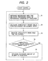
- JP-A-64-21451 a method replenishing the replenisher for an automatic developing apparatus for photosensitive lithographic printing plates, which measures the electric conductivity of the developer, compares the measured value with the calculated value that has been experimentally determined for the optimum sensitivity, and replenishes the replenisher in the case where the measured value is smaller than the calculated value.
- this method will be referred to as "conductivity-based replenishing method”.
- the conductivity-based replenishing method can replenish the appropriate amount of the replenisher and can appropriately keep the developer sensitivity, even with the changes in plate area, single surface/dual surface, or type of lithographic plate to be processed.
- the developer conductivity is affected (rises) by natural evaporation of water from the developer. Accordingly, when natural evaporation of water is promoted due to the affect of the installed conditions of the automatic developing apparatus or the like, an appropriate replenishing amount of the replenisher will be changed.
- the aforementioned conductivity-based replenishing method cannot deal with the changes of the appropriate replenishing amount of the replenisher due to the natural evaporation of water. Thus, when the natural evaporation of water is increased, the appropriate replenishment is not realized, thus failing in keeping the developer sensitivity appropriately.
- the electric conductivity of the developer exhausted by carbon dioxide absorbed in elapsed time differs from that of the one exhausted by plate processing when the sensitivity of the two are recovered to their proper values.
- a silicate-type processing agent exhibits 65mS/cm when recovered from CO 2 fatigue in contrast to 55mS/cm when recovered from plate processing
- a non-silicate-type processing agent exhibits 56mS/cm when recovered from CO 2 fatigue in contrast to 39mS/cm when recovered from plate processing. Therefore, if the frequency of processing, e.g., the processed amount per day changes, the electric conductivity for its optimal sensitivity tends to shift from the reference conductivity value set up in advance, thus it becomes impossible to keep the developer sensitivity appropriately.
- the object of the present invention is to provide an automatic developing apparatus and a method of replenishing the replenisher for said apparatuses, which can minimize the fluctuation of developing sensitivity against the changes in developing conditions, while using an economic and simple developing unit of the automatic developing apparatus, to thereby perform a stable development.
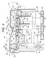
- An automatic developing apparatus for photosensitive materials includes:
- a method of replenishing a replenisher for a developer in an automatic developing apparatus for photosensitive materials includes the steps of:
- the "replenisher for developer” represents a processing solution to be replenished for maintaining a constant developing performance.
- the replenisher for developer includes a solution regulated by diluting an undiluted replenisher with a diluent such as water, or a replenisher which can use without dilution as it is.
- the replenisher regulated by previously diluting the undiluted replenisher may be replenished to the developer tank, or the undiluted replenisher and the diluent may be directly replenished to the developer tank.
- the integral amount of the replenisher is obtained by the sum of the undiluted replenisher and the diluent.
- the electric conductivity of the developer can be measured with any device well known in the art, including an AC conductivity meter, an AC bridge meter and other types of conductivity meters.
- an optimal condition of a measured current value and an oscillating frequency or the like of the measuring device depends on compositions of the developer and the like, but from the viewpoints of device protection and preventing the electrolysis of the aqueous developer, it is preferable that the current value makes low to some extent, that is, from several hundred mA to several ⁇ A.
- the frequency is from several hundred Hz to several hundred kHz.
- the electric conductivity of the developer containing electrolytes depends on the temperature of the aqueous solution, and the electric conductivity decreases as the temperature rises. Hence, it is more preferable to measure the electric conductivity with a measuring device equipped with a temperature sensor and a temperature compensating circuit. Further, the controller for replenishment can compensate the temperature by converting an actually measured liquid resistance value and liquid temperature into the electric conductivity value at the predetermined temperature.
- the sensor of the AC conductivity meter, the AC bridge meter, or other types of conductivity meters may be placed at any place where the sensor can be immersed in the developer at the measuring time and can measures its AC conductivity value of the developer.
- the sensor can be placed inside the developer circulation system of the automatic developing apparatus, particularly, in the developer tank or in the circulation pipe.
- a well-known measuring cell containing electrodes made of platinum, stainless steel, or the like can be used as the detecting device.
- the developer and the replenisher used in the present invention is aqueous alkaline solution with pH 9.0-13.5, and more preferably pH 10.0-13.3.
- aqueous alkaline solutions can be used as such a developer or a replenisher.
- inorganic base materials such as sodium or potassium silicate, trisodium, tripotassium or triammonium phosphate, disodium, dipotassium or diammonium hydrogenphosphate, sodium, potassium or ammonium bicarbonate, sodium, potassium or ammonium carbonate, sodium potassium or ammonium bicarbonate, sodium, potassium or ammonium borate, sodium, potassium, ammonium or lithium hydroxide, etc.
- organic ones such as monomethylamine, dimethylamine, trimethylamine, monoethylamin, diethylamine, triethylamine, monoisopropylamine, diispropylamine, triisopropylamine, n-butylamine, monoethanolamine, diethanolamine, triethanolamine, monoisopropanolamine, diisopropanolamine, ethylenimine, ethylenediamine, pyridine, etc.
- inorganic base materials
- the silicate composition is expressed by the molar ratio of SiO 2 to M 2 O ([SiO 2 ]/[M 2 O]).
- alkali agents used for the alkaline developer include those used for buffer solutions comprising a pair of weak acid and weak base.
- weak acids used for such buffer solutions those having an acid dissociation constant (pKa) of 10.0-13.3, more preferably 11.0-13.1, are suited.
- pKa acid dissociation constant
- sulfosalicylic acid having the third dissociation constant of 11.7 can be preferably used.
- polybasic acids at least one dissociation constant of which lies in the above-cited range can be applicable to the present invention.
- Strong bases to be combined with the weak acids cited above include sodium, ammonium, potassium or lithium hydroxide.
- Each of these bases can be used alone or in combination with each other.
- alkaline buffer agents preferable ones are the combinations of either of sulfosalicylic acid, salicylic acid, sucrose or sorbitol with sodium or potassium hydroxide. More preferable combinations comprise sorbitol and potassium or sodium hydroxide.
- alkali agents are used in such a manner as to realize preferable pH values by controlling their concentrations as well as combinations.
- surfactants can be contained in order to promote development, disperse development scum, or to enforce the ink receptivity of the image area of the printing plate.
- Preferable surfactants include anionic, cationic, nonionic or amphoteric compounds.
- surfactants include nonionic ones such as polyoxyethylene alkyl ethers, polyoxyethylene alkylphenyl ethers, polyoxyethylene polystyrylphenyl ethers, polyoxyethylene polyoxypropylenealkyl ethers, partial fatty acid esters of glycerin, partial fatty acid esters of sorbitan, partial fatty acid esters of pentaerithritol, monofatty acid esters of propylene glycol, partial fatty acid esters of sucrose, partial fatty acid esters of polyoxyethylene sorbitan, partial fatty acid esters of polyoxyethylene sorbitol, fatty acid esters of polyethylene glycol, partial fatty acid esters of polyglycerin, polyoxyethylene-added castor oil, partial fatty acid esters of polyoxyethylene glycerin, fatty acid diethanolamides, N,N-bis-2-hydroxyalkylamines, polyoxyethylene alkylamines, fatty acid esters of triethanolamine,
- anionic surfactants such as the salts of the following acids; fatty acid, abietic acid, hydroxyalkanesulfonic acid, alkanesulfonic acid, dialkylsulfosuccinic acid ester, straight and branched chain alkylbenzenesulfonic acid, alkylnaphthalenesulfonic acid, or alkylphenoxypolyoxyethylene propylsulfonic acid, polyoxyethylene alkylsulfophenyl ethersalt, sodium salt of N-methyl-N-oleyltaurine, bi-sodium salt of N-alkylsulfosuccinic acid monoamide, salts of petroleum sulfonic acid, sulfonated tallow, sulfate salts of fatty acid alkyl ester, alkylsulfate salts, polyoxyethylene alkyl ether sulfate salts, sulfate salts of fatty acid monoglyceride, polyoxyethylene
- polyoxyethylene group is replaceable to "polyoxyalkylene” including “polyoxymethylene”, “polyoxypropylene”, “polyoxybutylene”, etc., and those having the replaced groups can also be included in the scope of the invention.
- More preferable surfactants are fluorine-containing surfactants which include in their molecular structure a perfluoroalkyl group.
- Such surfactants include anionic ones such as perfluoroalkylcarboxylic acid salts, perfluoroalkylsulfonic acid salts, perfluoroalkylphosphoric acid esters, etc., amphoteric ones such as perfluoroalkylbetaine, etc., cationic ones such as perfluoroalkyltrimethylammnonium salts, etc., nonionic ones such as perfluoroalkylamine oxides, perfluoroalkylethylene oxide adducts, oligomers having perfluoroalkyl groups and hydrophilic groups, oligomers having perfluoroalkyl groups and oleophilic groups, oligomers having perfluoroalkyl groups, hydrophilic and oleophilic groups, urethanes having perfluoroalkyl groups and oleophil
- the surfactants described above can be used individually or in combination of two or more kinds of them in the concentration range of 0.001 to 10% by weight, or in a more preferable range of 0.01 to 5% by weight of the developer.
- Various development stabilizing agents can be incorporated in the developer and the replenisher of the present invention, including polyethylene glycol adducts of sucrose alcohol disclosed in JP-A-6-282079, tetraalkylammonium salts such as tetrabutylammonium hydroxide, etc. phosphonium salts such as tetrabutylphosphonium bromide, etc, and iodonium salts such as diphenyliodonium chloride, etc.
- anionic or the amphoteric surfactants disclosed in JP-A-55-51324, the water soluble cationic polymers disclosed in JP-A-55-95946, and the amphoteric polymer electrolytes disclosed in JP-A-56-142528 can be used.
- alkylene glycol-added organic boron compounds disclosed in JP-A-59-84241 water soluble surfactants comprising polyoxyethylene/polyoxypropylene. block type disclosed in JP-A-60-111246, alkylenediamines substituted with polyoxyethylene polyoxypropylene disclosed in JP-A-60-129750, polyethylene glycol having weight-averaged molecular weight of not less than 300 disclosed in JP-A-61-215554, fluorine-containing surfactants having a cationic group disclosed in JP-A-63-175858, the water soluble ethylene oxide-added compounds obtained by adding 4 or more moles of ethylene oxide to acids or alcohols disclosed in JP-A-2-39157, water soluble polyalkylene compounds, etc.
- organic solvents can be added to the developer and the replenisher of the present invention.
- Suitable organic solvents should have a solubility to water of 10% by weight or less, more preferable 5% by weight or less.
- solvents include 1- and 2-phenylethanol, 3-phenyl-1-propanol, 4-phenyl-1-butanol, 4-phenyl-2-butanol, 2-phenyl-1-butanol, 2-phenoxyethanol, 2-benzyloxyethanol, o-methoxybenzyl alcohol, m-methoxybenzyl alcohol, p-methoxybenzyl alcohol, benzyl alcohol, cyclohexanol, 2-, 3- and 4-methylcyclohexanol, N-phenylethanolamine, N-phenyldiethanolamine, etc.
- a suitable range for the content of such organic solvents is from 0.1 to 5% by weight of the total amount of the working solution.
- the content has a close relation to the amount of the surfactant in use; with the increase of organic solvent, the amount of surfactant should preferably be increased.
- the organic solvent will sometimes not be perfectly dissolved in the composition, thus failing in securing a desirable level of developing capability.
- the developer and replenisher compositions of the present invention can further contain reducing agents in order to prevent lithographic printing plates from staining.
- Reducing agents are particularly effective for the development of negative-working photosensitive lithographic printing plates containing photosensitive diazonium salt compounds.
- Particularly preferred organic reducing agents include phenolic compounds such as thiosalicylic acid, hydroquinone, Methol (N-methylaminophenol), methoxyquinone, resorsine, 2-methylresorsine, etc.
- amine compounds such as phenylenediamine, phenylhydrazine., etc.
- Particularly preferred inorganic reducing agents include the sodium, potassium and ammonium salts of inorganic acid such as sulfurous, hydrogensulfurous, phosphorous, monohydrogenphosphorous, dihydrogenphosphorous, thiosulfuric, dithionous acid, etc.
- inorganic acid such as sulfurous, hydrogensulfurous, phosphorous, monohydrogenphosphorous, dihydrogenphosphorous, thiosulfuric, dithionous acid, etc.
- the most preferable one is sulfite salts.
- the preferable range for the content of the reducing agent is from 0.05 to 5% by weight of the working developer.
- the developer and replenisher compositions of the present invention can further contain organic carboxylic acids.
- Preferable acids are aliphatic and aromatic carboxylic acids with 6-20 carbon atoms.
- Preferable aliphatic acids include caproic, enanthic, capryl, lauric, myristic, palmitic, stearic acids, etc., particularly suitable ones being C 8-12 alkanoic acids.
- Unsaturated fatty acids containing double bonds in their carbon chain can be used. Branched chain fatty acids can also be used.
- Suitable aromatic carboxylic acids are those comprising benzene ring, naphthalene ring, anthracene ring substituted with a carboxyl group, exemplified by o-chlorobenzoic acid, p-chlorobenzoic acid, o-hydroxybenzoic acid, p-hydroxybenzoic acid, o-aminobenzoic acid, p-aminobenzoic acid, 2,4-dihydroxybenzoic acid, 2,5-dihydroxybenzoic acid, 2,6-dihydroxybenzoic acid, 2,3-dihydroxybenzoic acid, 3,5-dihydroxybenzoic acid, gallic acid, 1-hydroxy-2-naphthoic acid,. 3-hydroxy-2-naphthoic acid, 2-hydroxy-1-naphthoic acid, 1- and 2-naphthoic acid, etc.
- hydroxynaphthoic acid is one of the most suitable aromatic acids.
- the above described aliphatic and aromatic carboxylic acids can be preferably used in the form of sodium, potassium or ammonium salt to secure a high solubility to water.
- content of organic carboxylic acid in the developer composition of the present invention there is no special limitation on the content of organic carboxylic acid in the developer composition of the present invention, but, in general, contents below 0.1% by weight cannot exert a sufficient effect; on the other hand,.when the acid content exceeds 10% by weight, the effect is saturated, and tends to hinder the solution of other additives. Accordingly, the practical range lies between 0.1 and 10% and more preferably 0.5 and 4% by weight of the working developer.
- Antiseptics can be added to the developer, washing water or finishing liquid.
- Known antiseptics for fabric, wood processing, food, cosmetic, agricultural chemical, etc. can be used. Examples include quaternary ammonium salts, monovalent, bivalent or polyvalent phenol derivatives, imidazole derivatives, pyrazolopyrimidine derivatives, monovalent naphthol, carbonates, sulfone derivatives, organic tin compound, cyclopentane derivatives, phenyl derivatives, phenol ether derivatives, phenol ester derivatives, hydroxylamine derivatives, nitrile derivatives; naphthalines, pyrrole derivatives, quinoline derivatives, benzothiazole derivatives, secondary amines, 1,3,5-triazine derivatives, thiadiazole derivatives, anilide derivatives, pyrrole derivatives, halogen derivatives, dihydric alcohol derivatives, dithiols, cyanic acid.
- anticeptics are the salts of pyridinethiol-1-oxide, salicylic acid and its salts, 1,3,5-trishydroxyethylhexahydro-S-triazine, 1,3,5-trishydroxymethylhexahydro-S-triazine, 1,2-benzisothiazoline-3-one, 5-chloro-2-methyl-4-isothiazoline-3-one and 2-bromo-2-nitro-1, 3-propanediol.
- the addition levels of these antiseptics are determined so as for the antiseptics to work in a stable and effective manner.against bacteria, mold, yeast fungi, etc., depending on the kinds of bacteria, etc. A preferable range is usually 0.01-4% by weight.
- combined two or more kinds of antiseptics are preferably used together to protect the developer from various kinds of bacteria, mold, etc.
- the developer and replenisher compositions used in the present invention can further contain still other ingredients such as anti-forming agent, water softener, etc., depending on the need.
- Softeners for hard water include, for example, polyphosphoric acid and its sodium, potassium or ammonium salt, amino-polycarboxylic acid such as ethylenediamineteteraacetic acid, diethylenetriaminepentaacetic acid, triethylenetetraminehexaacetic acid, hydroxyethylethylenediaminetriacetic acid, nitrylotriacetic acid, 1,2-diaminocyclohexanetetraacetic acid, 1,3-diamino-2-propanol tetraacetic acid, etc., sodium, potassium or ammonium salt of the amino-polycarboxylic acids described above, aminotri(methylene phosphonic acid), ethylenediamine-tetra(methylene phosphonic acid), diethylenetriaminepenta(methylene phosphonic acid), triethylenetetraminehe
- a preferable range for the concentration of such a softener depends on its chelating capability as well as the hardness of the water in concern; generally speaking, based on the working developer, 0.01-5% by weight and more preferably 0.01-0.5% by weight is recommended. Lower concentration levels than the described range fail to exert a sufficient softening effect; on the other hand, higher addition levels tend to have adverse effects on developed images such as density drop, etc.
- the remaining part of the developer and the replenisher consists of water, to which still various additives known in the art can be added.
- the developer and the replenisher of the present invention take a condensed form in which they have an increased concentration of ingredients to be diluted with water in use.
- the degree of condensation is determined so as to cause neither phase separation nor deposition of the ingredients.
- the temperature of the developer should be kept at 15-40°C, and more preferably 20-35°C.
- the developing time is preferably 5-60sec, and more preferably 7-40sec.
- the method of the invention can be applied not only to the above-cited developers, but also to those described in EP0836120A1, EP0908785A, EP090830XA, EP0914941A1, JP-A-11-327163 and JP-A-11-327160 and Japanese Patent Application No. 2000-255670.
- a type of positive-working image recording material is proposed in JP-A-7-285275, JP-A-11-119419 and Japanese Patent Application 11-182751 in which the material can record images via an infrared laser exposure.
- the photosensitive material consists of a binding agent such as cresol resin, a substance that generates heat by absorbing light, and another substance that is thermally decomposable such as quinonnediazide and which substantially prevents said binding agent from dissolving in the developer when not decomposed.
- the substance generating head by absorbing light generates head, thus causing the exposed areas to dissolve.
- JP-A-7-20625, JP-A-11-218903, Japanese patent application Nos. 11-308286 and 11-332936 disclose a type of negative-working image recording material comprising a compound that generates acid upon the decomposition by light or heat, a cross-linking agent that works by the presence of acid, at least one kind of alkali-soluble resin, and an infrared light absorbing agent.
- a negative-working image recording material at exposed areas, the substance generates heat by absorbing light, the above compound generates acid by decomposing by the heat, and the acid thus formed promotes the cross-linking of the alkali-soluble resin with the cross-linking agent, to thereby perform an image recording.
- the present invention can use such image recording materials described above as a lithographic printing plate.
- the image recording on lithographic printing plates is performed by an infrared laser exposure, which are subjected to heat treatment, if needed, and then to perform a development proceeding.
- the present invention is also applicable to the processing of the photosensitive lithographic printing plates based on the photopolymer compositions as disclosed in Japanese Patent Application Hei.10-251521, JP-A-2000-39724 and Japanese Patent Application 2000-276811.
- the photosensitive lithographic printing plates based on the photopolymer compositions consist of, on a substrate that an aluminum plate is subjected to a hydrophilic proceeding, a photo-polymerizable layer containing a compound having an ethylenic double bond capable of addition polymerization and a polymer having a cross-linkable group in its side chain.
- such a type of lithographic plate is exposed imagewise with laser light and then is developed.
- the present invention is also applicable to the processing of. the positive-working photosensitive lithographic printing plates disclosed in JP-A-9-274324, JP-A-2000-231188 and Japanese Patent Application No.2000-13656, having been in a wide use in the conventional art.
- This type of lithographic plate consists of an aluminum plate as a support body on which a photosensitive layer containing an o-quinonediazide compound. O-quinonediazide compounds are known to be converted to carboxylic acids by UV exposure, thus the layer can be developed with an aqueous alkaline solution to cause a removal of the exposed areas of the photosensitive layer, whereby the support body surface is exposed.
- the exposed support surface of the aluminum support body which is hydrophilic, at the exposed (non-image portion) areas holds water by the development and repels oil based ink on the printer.
- the image areas where the photosensitive layer remains accept oil based ink and repels water.
- a cresol-novolac resin as the binder for the o-quinonediazide compound.
- the method of the present invention is applicable to the proceeding of the negative-working photosensitive lithographic plate, which is disclosed in JP-A-7-295212 and Japanese Patent Application No. 2000-103135.
- an automatic developing apparatus 2 includes a developing unit 6 which develops photosensitive lithographic printing plates (hereinafter, referred to as "PS plates") 4, a finishing unit 8 which first washes off the developer adhered to the developed PS plate 4 and which then coats a gum solution thereon, and a drying unit 10 which dries the PS plate coated with the gum solution.
- PS plates photosensitive lithographic printing plates
- finishing unit 8 which first washes off the developer adhered to the developed PS plate 4 and which then coats a gum solution thereon
- a drying unit 10 which dries the PS plate coated with the gum solution.
- a pre-heating unit (not shown in Fig. 1) can be provided.
- the pre-heating unit is arranged at the upstream side of the developing unit 6 along the transport direction, and has a function of keeping the surface temperature of the PS plate 4. during a predetermined period while the PS plate .4 is transported.
- the PS plate 4 inserted into the pre-heating unit is automatically transported along with the application of heat toward the next processing.
- the developing apparatus 2 may include a pre-washing unit (not shown in Fig. 1).
- the pre-washing unit is arranged at the upstream side of the developing unit 6 and at the downstream side of the pre-heating unit along the transport direction.
- the pre-washing unit has a function of washing and cooling the surface of the PS plate 4 by washing water while transporting the PS plate 4.
- the PS plate 4 inserted into the pre-washing unit is transported towards the developing unit 6 that carries out the next processing.
- An insert port 14 is formed in a sidewall 12 of the automatic developing apparatus 2, and the PS plate 4 inserted from the insert port 14 is sent to the developing unit 6 by transport rollers 16. At the insert port 14, there is provided a rubber blade 18 that closes the insert port 14 except when a PS plate 4 is being inserted.
- a developer tank 20 of the developing unit 6 transport rollers 22, brush rollers 24 and squeeze rollers 26 are equipped in this order from the upstream side in the transporting direction, and backup rollers 28 are also equipped between the former three rollers in an appropriate manner.
- the PS plate 4 is immersed in and developed by the developer solution while being transported by the transport roller 22.
- the finishing unit 8 contiguous to the developing unit 6 includes a first finishing unit 8a and a second finishing unit 8b.
- Each of these finishing units 8a, 8b is equipped with transport rollers 30a, 30b transporting the PS plate 4, nozzles 34a, 34b that spray the gum solution stored in finishing tank 32a, 32b onto the PS plate 4.
- the PS plate 4 after the development is coated with the gum solution by the nozzles 34a, 34b while being transported by the transport rollers 30a, 30b.
- the gum solution stored in the second finishing tank 32b of the second finishing unit 8b located at the downstream side is overflowed to be supplied to the first finishing tank 32a of the first finishing unit 8a.
- the gum solution may be supplied from the second finishing tank 32b to the first finishing tank 32a with using a pump or the like.
- the drying unit 10 contiguous to the finishing unit 8 is equipped with a guide roller 36 and a pair of rollers with skewers 38 in this order from the upstream side in the transporting direction.
- a drying device such as a warm-air supplying unit, a heating unit, etc. not'shown in the figure.
- a discharge port 40 through which the dried PS plate 4 is discharged out of the apparatus.
- a shutter 44 is provided in a passage 46 between the drying unit 10 and the finishing unit 8, and the shutter 44 is kept the passage 46 closed except when the PS plate 4 is moving along the passage 46.
- the gum solution stored in a gum solution tank 56 is fed by a pump 77, and a diluent (water) 57 stored in a diluent for replenishment storage tank 53 is also fed by a diluent for replenishment supplying pump 78.
- the replenishing amount of the gum solution to that of the diluent is 1:1.
- the gum waste solution overflowed from the first finisher tank 32a is collected to the waste tank 54 as well as the developer waste solution.
- a box-shaped shielding cover 60 is provided integrally with the tank walls.
- the bottom wall of the shielding cover 60 is structured to have plural curved depressions so as not to touch with upper circumferential surfaces of the rollers 22, 24 and 28.
- the shielding cover 60 is of box-shape, an airtight space is formed above the developer tank 20, and thus the amount of air in the developing unit 6 is minimized. Further, owing to the presence of the shielding cover 60, the area of the developer directly contacted with the air is made as small as possible.
- plural rubber blades 62 are provided at proper places in such a manner that a substantially airtight space is formed from the developing unit 6 to the second finishing unit 8b by preventing the external atmosphere from entering inside.
- the space between the developing unit 6 and the first finishing unit 8a is also airtightly formed by the rubber blade 62 so as to prevent the air in first finisher 8a from flowing into the developing unit 6.
- the developing unit 6 is substantially airtight except the period of the passage of the PS plate 4 through the insert port, which the air is slightly entered.
- a circulation pipe 80 of the developer in which are installed a developer circulation pump 71, a conductivity sensor 73 and a filter (not shown).
- the developer circulation pump 71 sucks the developer in the tank 20 through the hole provided in the bottom of the tank 20 into the pipe 80, puts the developer into circulation, and again ejects the developer back into the tank 20.
- the filter filters the developer flowing through the pipe 80.
- the conductivity sensor 73 measures the conductivity of the developer passing through the pipe 80.
- the developing unit 6 is equipped with a replenishing device comprising replenishing pipes 90 and 91, an undiluted replenisher storage tank 55 connected to the replenishing pipe 90, an undiluted replenisher supplying pump 74 intervened in the replenishing pipe 90, the diluent for replenishment storage tank 53 connected to the replenishing pipe 91, and a diluent for replenishment supplying pipe 76 intervened in the replenishing pipe 91.
- the developing waste solution which overflows the developer tank 20 is collected in the waste tank 54.
- the pair of pipes 90 and 91 that supply the replenisher obtained by diluting the undiluted replenisher 58 with the diluent for replenishment 57.
- the replenishing pipe 90 for the undiluted replenisher 58 is connected to the undiluted replenisher storage tank 55 (at the bottom left in Fig. 1) -
- the undiluted replenisher supplying pump 74 is involved in the pipe 90, and supplies the undiluted replenisher 58 from the undiluted replenisher storage tank 55 to the developer tank 20.
- the replenishing pipe 91 for the diluent for replenishment 57 is connected to the diluent storage tank 53 (at the bottom middle in Fig. 1).
- the diluent supplying pump 76 is involved in the replenishing pipe 91, and supplies the diluent for replenishment (water) 57 from the diluent storage tank 53 to the developer tank 20.
- the replenishing pipe 91, the diluent for replenishment supplying pump 76 and the diluent storage tank 53 constitute a diluent supplying system.
- Both of the undiluted replenisher supplying pump 74 and the diluent for replenishment supplying pump 76 are controlled by a controlling ROM 51 being a condition memorizing unit and a controller 50 comprising a time measuring device 52, wherein the former 74 is controlled based on signals from a plate detector 27 and a time measuring device 52 while the latter 76 is controlled based on signals from the plate detector 27, the time measuring device 52 and the conductivity sensor 73.
- the controller 50 controls the undiluted replenisher supplying pump 74 and the diluent supplying pump 76 based on the signals from the plate detector 27 which can judge whether a plate is being processed or not and which can measure the area, etc. of the transported plate, and carries out the replenishment referring to the replenishing conditions established according to the actual operating conditions of the automatic developing apparatus 2 and memorized in the controlling ROM 51.
- the controller 50 supplies the amount of the replenisher for developer (the sum of the undiluted replenisher 58 and the diluent for replenishment 57) corresponding to the replenishing condition from the undiluted replenisher storage tank 55 and the diluent for replenishment storage tank 53 after processing every plate.
- the replenishment may be performed after processing a fixed plural number of plates, not every plate.
- the controller 50 carries out the replenishment when the time measuring device 52 detects the elapse of a predetermined time, referring to the replenishing conditions established according to the actual operating conditions of automatic developing apparatus 2.
- the controller 50 supplies the amount of the replenisher for developer (the sum of undiluted replenisher 58 and the diluent for replenishment 57) corresponding to the replenishing condition memorized in the controlling ROM 51 from the undiluted replenisher storage tank 55 and the diluent storage tank 53 coping with the effect of time elapse.
- the controller 50 supplies the diluent for replenishment 57 to developer tank 20 from the diluent storage tank 53.
- the undiluted replenisher supplying pump 74 and the diluent for replenishment supplying pump 76 are controlled by the controller 50 on the basis of the signals from the time measuring device 52 and the plate detector 27 with reference to the predetermined replenishing conditions depending on actual operating conditions, whereby the replenisher is supplied to the developer tank 20 by the two pumps to compensate the effects of time elapse as well as processing.
- the diluent supplying pump 76 by the controller 50 based on the signals from the conductivity sensor 73, the diluent is replenished to the developer tank 20 from the diluent storage tank 53 until the conductivity of the developer replenished with the replenisher becomes below the predetermined target value.
- step S1 the replenishment of the replenisher is carried out with a lapse of time and at every processing in the predetermined condition, based on the replenishing conditions (memorized in controlling ROM 51) predetermined depending on the actual operating conditions of the automatic developing apparatus 2.
- the target value of conductivity is calculated from the replacement ratio of the replenisher defined by a ratio that the charged developer at the start of the developing processing is replaced with the replenisher and/or the diluent replenished to lower the conductivity of the developer.
- the conductivity sensor 73 measures the conductivity of the developer with a lapse of a fixed time.
- step S4 the target conductivity value obtained at S2 is compared with the measured conductivity value obtained at S4.
- FIG. 3 shows the structure of the automatic developing apparatus of the second embodiment of the invention.
- processing units inside thereof are covered with outer panels 114.
- a developing unit 122 including a developer tank 118 for developing a PS plate 112 and an overflow pipe 120 which collects the developer overflowed from the developer tank 118, a water washing unit 124 which washes off the developer adhered to the PS plate 112 and a finishing unit 126 which desensitizes the washed PS plate 112 by coating.
- a gum solution- The washing unit 124 has a washing water tank 128, and the finishing unit 126 has a gum solution tank 130.
- a slit-shaped insert port 202 and a slit-shaped discharge port 204 In the outer panel 114, there are. provided a slit-shaped insert port 202 and a slit-shaped discharge port 204. In the upper plane of panel 114, there is provided an insert port for reentry 250 (sub insert port) for the insertion of the PS plate 112 between the developing unit 122 and the washing unit 124. This sub insert port 250 is used to perform the other processing than development on the PS plate 112.
- the sub insert port 250 there is a blade 252, the leading edge of which is in contact with the outer panel 114 acting as a guiding support surface for the sub insert port 250.
- the base portion of the blade 252 is fixed to the rear side of outer panel 114 through an intervening bracket 254. With such a structure, the sub insert port 250 is usually kept in a closed state by the blade 252.
- the drying unit (not shown) dries the PS plate 112 by blowing a warm air to the both surfaces thereof while transporting by plural rollers (not shown) the PS plate 112 sent from finishing unit 126.
- a pair of transport rollers 132 are equipped at the insertion side of the PS plate 112 to the developer tank 118 in the developing unit 122.
- the PS plate 112 is inserted from the insert port 202 between the pair of transport rollers 132.
- a rubber blade 206 is provided at the downstream side of and close to the transport roller 132.
- the leading edge of the blade 206 is in contact with the sidewall of the developer tank 118 of the developing unit 122, and its base portion is attached to the outer panel 114 through a bracket 256.
- the bracket 256 includes a fixed part 256A and a sliding part 256B attached to the fixed part 256A with a wing nut 258, and the blade 206 is fixed to the sliding part 256B.
- the blade 206 is so constructed that its leading edge can be separated from the sidewall of the developer tank 118 by moving the sliding part 256B relative to the fixed part 256A with the wing nut 258 loosened.
- a plate detector 208 is equipped which detects whether the PS plate 112 is passing or not and which also can measure the area of the plate, etc.
- the developer tank 118 has a cross-sectional shape of a substantially inverted mountain, the top of the tank 118 is open and the center portion of the bottom thereof protrudes downward.
- the tank 118 has a pump 260 that sucks the developer in the tank 118 and blows out it from spray pipes 144 and 272 that will be described later, whereby the developer stored in the developer tank 118 is circulated.
- the flowing developer passes through a conductivity sensor 262 which measures a conductivity of the developer.
- the undiluted, replenisher is supplied from an undiluted replenisher storage tank 266 to developer tank 118 by a pump 264.
- a diluting water is also supplied from the water tank 128 to the developer tank 118 by a pump 286.
- Both of the pumps 264 and 286 are controlled by the controller 50 comprising the controlling ROM 51 being a condition memorizing unit and a time measuring device 52 whereby the former 264 is controlled based on signals from the plate detector 208 and the time measuring device 52, while the latter 286 is controlled based on signals from the plate detector 208, the time measuring device 52 and the conductivity sensor 262.
- the controller 50 comprising the controlling ROM 51 being a condition memorizing unit and a time measuring device 52 whereby the former 264 is controlled based on signals from the plate detector 208 and the time measuring device 52, while the latter 286 is controlled based on signals from the plate detector 208, the time measuring device 52 and the conductivity sensor 262.
- the controller 50 comprising the controlling ROM 51 being a condition memorizing unit and a time measuring device 52 whereby the former 264 is controlled based on signals from the plate detector 208 and the time measuring device 52, while the latter 286 is controlled based on signals from the plate detector 208, the time measuring device 52 and the conductivity sensor 262.
- a guide plate 268 in the upstream side there are arranged a guide plate 268 in the upstream side, and plural guide rollers 134 and a rotary brush roller 270 in the downstream side. These guide rollers 134 and rotary brush roller 270 are bridged over the pair of the sidewalls of the tank 118 in a revolvable manner.
- a guide roller 136 of a relatively large diameter is arranged above the guide plate 268, and rotary brush rollers 138 and 270, and guide roller 140 are arranged above the guide roller 134.
- a pair of squeeze rollers 142 is provided which squeezes the surface of the PS plate 112.
- the overflow pipe 120 is arranged at the most downstream side of tank 118.
- the overflow pipe 120 conducts the developer to a waste tank 284 when the liquid surface of the developer exceeds a predetermined level.
- a liquid cover is disposed on the surface of the developer in the developer tank 118.
- the liquid cover 150 has an arc-shaped projected part corresponding to the brush roller 138 and the guide roller 140 contiguous to the roller 138.
- the cover 150 is contacted with the liquid surface of the developwer to prevent the developer from being directly contacted with air, and is slidably held at its both edges along the transport direction of the PS plate 112 by the sidewalls (not shown) in such a manner as to permit a vertical motion of the cover in accordance with changes of the level of the liquid surface.
- the downstream end of the liquid cover 150 along the transport direction is in contact with the leading edge of a blade 274 that is fixed to the outer panel 114 via a bracket 276.
- the blade 274 thus structured, the liquid surface of the developer exposed at the downstream end of the liquid cover 150 in the transport direction is. separated from the upper portion of the liquid cover 150.
- the blade 206 in the vicinity of the insert port 202 the upper space of the liquid cover 150 is perfectly separated from the external atmosphere, to thereby prevent the evaporation of the developer. Note that each side end of the blade 206 is in a tight contact with the sidewall of developer tank 118.
- a pair of rollers 154 are arranged which holds and transports the PS plate 112 while simultaneously squeezing the developer from the surface of the PS plate 112.
- the automatic developing apparatus 100 has the water washing tank 128 of the water washing unit 124 at the downstream side of the developing unit 122. Above the water washing tank 128, two pairs of transport rollers 152 and 153 are placed.
- the washing water tank 128 stores washing water used to remove the developer from the PS plate 112 fed from the developer tank 118.
- a spray pipe 156 is provided at the upstream side of the top transport roller 153 and above the transport passage.
- the outer surface of the pipe 156 has plural discharge holes communicating with the inside of the pipe 156.
- the washing water dipped by the pump 280 from the tank 278 is dropped from the spray pipe 156 on the top roller of the transport rollers 153. With the rotation of the top roller 153, the washing water readily spreads on and thus effectively cleans the surface of plate 112.
- the lower portion of the bottom transport roller 152 or 153 is immersed in the washing water stored in a pan 162.
- the bottom roller pulls up the washing water so as to clean the rear surface of plate 112, and prevent the dry-up of the top roller 152 or 153.
- the washing water spread laterally along the front surface of plate 112 falls into the pan 162 from the.both side edges of the PS plate 112, and the washing water scooped up from the pan 162 washes the rear surface of the PS plate 112.
- the water overflowed from pan 162 is conducted to the water washing tank 128, in which an overflow pipe 282 is equipped so as to collect the washing water of the volume exceeding the predetermined liquid level to the waste tank 284.
- the washing water tank 128 and the developer tank 118 are connected with each other via a pump 286, which may conduct the wash water in the washing water tank 128 to the developer tank 118 as the diluent for supplying the replenisher to the developer tank 118.
- each spray pipe sprays the gum solution scooped up by a pump 292 from a gum solution tank 290 onto the front or the rear surface of the PS plate 112.
- the transport rollers 178 squeezes the gum solution sprayed with spray pipe 182 for the desensitization of the surface of the PS plate 112.
- the gum solution squeezed off the surface of the PS plate 112 is collected to the gum solution tank 130.
- the gum solution in the tank 130 is circulated by the pump 294.
- the gum solution tank 130 is provided with an overflow pipe 296, which acts to collect the gum solution of the volume exceeding the predetermined liquid level to the waste tank 284.
- the lower portion of the bottom transport roller 178 is immersed in the gum solution stored in the gum solution tank 130, and the bottom transport roller 178 scoops up the gum solution to coat the rear surface of the PS plate 112 for desensitization.
- the gum solution carried by bottom transport roller 178 is also transferred. onto the top transport roller 178, thus preventing the dry-up of the top roller 178 and also the deposition of the. solution ingredients on the surface of the top roller 178.
- the PS plate 112 that has been subjected to the treatment in the finishing unit 126 is fed through the discharge port 204 of a casing 200 to the drying unit (not shown).
- a lid body 210 serving as a shutter is provided at the discharge port 204.
- the lid body is supported by a pivot shaft 212, which can rotate with a driving means such as, for example, a solenoid (not shown).
- the pivot shaft 212 rotates in accordance with the signal from the plate detector 208 located close to the insert port 202 to detect the passage of the PS plate 112. More specifically, the lid body 210 is retained at a substantially horizontal position (an open condition of the discharge port 204) during the period that the PS plate 112 is detected by the plate detecting sensor 208, and a predetermined period after the detection of the PS plate 112, and the lid body 210 is retained at a vertical position (a closed condition of the discharge port 204) during the time other than such period.
- processing tanks such as the developer tank 118, the washing water tank 128, the gum solution tank 130, etc.; are covered with the casing 200 comprising the outer panel 114 and the main box 108, etc.
- the insert port 202 is closed as the blade 206 is in contact with the sidewall of the developer tank 118.
- the discharge port 204 is also closed with the lid body 210 in the vertical position since the sensor 208 does not detect the PS plate 112.
- the sub insert port 250 is also closed with the blade 252, and the space above the liquid surface cover 150 of the developing unit 122 is also closed with the blades 206 and 276.
- the developer in the. developer tank 118, the washing water in the washing water unit 124 and the gum solution in the finishing unit 126 are well protected from the external atmosphere, and substantially no deterioration of the processing solutions due to CO 2 takes place. Since the decline of developing capability caused by the aging fatigue is minimized in the embodiment, the replenishing amount of the undiluted replenisher in the developing unit 122 can be drastically reduced.
- the liquid surface of the developer in the developer tank 118 is covered with the liquid surface cover 150, the contact -protecting effect of the developer with the external atmosphere is noticeable.
- the opening period of the lid body 210 is made as short as possible.
- control of the controller 50 is performed in a similar manner as was described in the first embodiment with reference to Fig. 2, the description on the control will be omitted.
- Example 2 As is seen from Table 2, the replenishing method of Example 1 is almost equivalent to the conventional conductivity-based replenishing method, but far better than the conventional plate area-based replenishing method.
- Example 2 shows that the replenishing method of Example 1 can suppress the maximum range of pH fluctuation far better than the conventional, conductivity-based replenishing method.
- the reason is as follows.
- Example 1 since the diluent is replenished based on the detected electric conductivity of the developer, even when an abnormal rise of the conductivity by water evaporation is caused, the fluctuation of the sensitivity can. be reduced by compensating the diluent fallen short by the natural evaporation.
- the conventional, conductivity-based replenishing method stops the replenishment of the replenisher as a result of a misjudging that the sensitivity is high when the abnormal rise of conductivity by water evaporation is caused. Such a countermeasure leads to a decline of the sensitivity.
- the plate was immersed in a 30% aqueous sulfuric acid for 2min at 55°C for desmatting, then subjected to. anodic oxidation with a current density of 14A/dm 2 to form a 2.5g/m 2 anodic. oxide film followed by rinsing with water.
- substrate [A] The resulting plate is designated as substrate [A].
- Substrate [A] was treated with 0.1% by weight aqueous solution of sodium silicate at 20°C for 10sec to provide substrate [B]
- Substrate [B] thus prepared was coated with the organic compound of the following formulation, and dried at 100°C for 10sec to form an organic intermediate layer with the coated density shown below.
- a photosensitive layer was formed on substrate [B] by coating a photosensitive solution [A].
- the coated amount of the layer on dry base was 1.15g/m 2 .
- a matt layer was formed according to the method disclosed in JP-A-61-28986 to provide a photosensitive lithographic printing plate.
- Desensitizing liquid [A] Gum Arabic 3.6g Potato starch denatured with enzyme 36.6g Corn starch denatured with enzyme 7.4g Phosphorylated waxy corn starch 3.6g Sodium salt of dioctylsulfosuccinic acid ester 1.82g Ammonium dihydrogenphosphate 0.74g Citric acid 1.3g ⁇ Alanine 2.40g Sodium ⁇ -olefinslulfonate 0.88g EDTA-tetrasodium salt 0.54g Ethylene glycol 3.6g Benzyl alcohol 4.6g Copolymer A 0.50g Sodium dehydroacetate (antiseptic) 0.08g Emulsion type, silicone-based anti-forming agent 0.04g water 34.2g
- Example 2 As is seen from Table 3, the replenisher supplying method of Example 2 is almost equivalent to the conventional, conductivity-based replenishing method, but far better than the plate area-based replenishing method in terms of the maximum range of pH fluctuation.
- Developer DP-7 a product of Fuji Photo Film Co., Ltd., was diluted in the ratio of 1/9.
- An aqueous solution comprising the following ingredients was prepared in such a quantity as to fill the developer tank.
- a potassium salt comprising D-sorbitol as an unreducing saccharide and potassium oxide as a base 5.0% Olfin AK-02 (made by Nisshin Chemical Co., Ltd.) 0.015% Surfactant D-1105 (made by Takemoto Yushi Co., Ltd.) 0.010% Water to make 1000mL The following compound 0.01g
- Developer DP-4 a product of Fuji Photo Film Co., Ltd., was diluted in the ratio of 1/8.
- Developer LP-D a product of Fuji Photo Film Co., Ltd., was diluted in the ratio of 1/10.
- Developer replenisher DP-7RW a product of Fuji Photo Film Co., Ltd., was used.
- composition was prepared as Replenisher B.
- An aqueous solution comprising the following ingredients was prepared in such a quantity as to fill the developer tank.
- a potassium salt comprising D-sorbitol as an unreducing saccharide and potassium oxide as a base 5.0% Olfin AK-02 (made by Nisshin Chemical Co., Ltd.) 0.015% Water to make 1000mL.
- Olfin AK-02 made by Nisshin Chemical Co., Ltd.
- Developer replenisher DP-4R a product of Fuji Photo Film Co., Ltd., was used.
- Developer replenisher LP-DR a product of Fuji Photo Film Co., Ltd., was used.
- Photosensitive printing plates A to J used in Examples 3 to 10 and Comparative Examples 1 to 9 are described as for their preparing methods, processings prior to development and exposure conditions.
- a photosensitive printing plate A was prepared according to Example 1 of JP-A-2000-231188.
- the plate was image exposed for lmin with a printer FT26V2UPNS, a product of Nuarc Co., Ltd. in USA equipped with a 2kW metal halide lamp as the light source.
- the developer speed was evaluated with a step wedge (a product. of Fuji Photo Film with 0.15 step difference in density) image obtained by the same exposure condition as described above.
- Plate B was prepared according to Example 1 of JP-A-7-295212.
- the plate was image exposed by 50 counts with a printer FT26V2UPNS, a product of Nuarc Co., Ltd. in USA equipped with a 2kW metal halide lamp as the light source.
- the developer speed was evaluated with a step wedge (a product of Fuji Photo Film with a 0.15 step difference in density) image obtained by the same exposure condition as described above.
- Fluorinated aliphatic group-containing compound P-2 was thus obtained with a yield of 68.4g.
- GPC analysis proved that the solid product is a polymer with a weight-averaged molecular weight of about 30,000.
- a JIS A 1050 aluminum plate with a thickness of 0.24mm and a width of 1030mm was continuously processed as follows.
- the back surface of the plate was coated with the following diluted sol-gel transforming mixture with a coating bar, and dried at 100°C for lmin.
- the coated weight of this back coating was 60mg/m 2 on dry base.
- the front surface of the plate was provided with an organic intermediate layer having a coated weight of 7mg/m 2 after drying by coating the following composition with a coating bar and drying at 100°C for 10sec.
- a photosensitive coating solution of the following composition On the organic intermediate layer of the plate was coated a photosensitive coating solution of the following composition with a coating bar. After drying at 100°C for 60sec, the coated weight was 1.15g/m 2 .
- a matt layer was formed onto the surface of the photosensitive layer thus formed by spraying a matt layer forming resin solution as follows.
- a 12% aqueous solution of methyl methacrylate/ethyl acrylate/acrylic acid copolymer (weight ratio of initially charged monomer 65:20:15) part of which had been rendered to the sodium salt (in some cases, potassium or ammonium salt) was prepared.
- This matt layer forming solution was sprayed with a rotary mist forming electrostatic coating machine under the following conditions. Rotation of the mist forming head 15,000rpm Feeding rate of the solution 65mL/min Voltage applied to the mist forming head -75kV Surrounding temperature during coating 25°C Relative humidity of the surrounding atmosphere 50%RH
- the coated surface was moistened by spraying water vapor after 1.5sec following the coating, and then dried by blowing a warm air stream of 60°C, 10%RH for 5sec starting from 3sec after moistening.
- the coated weight of the matt layer was 130mg/m 2 .
- the finished photosensitive plate was given an image exposure for lmin with a printer FT26V2UPNS, a product of Nuarc Co., Ltd. in USA equipped with a 2kW metal halide lamp as light source.
- the developer speed was evaluated with a step wedge (a product of Fuji Photo Film with 0.15 step difference in density) image obtained by the same exposure condition as described above.
- the plate was immersed in 25% aqueous sodium hydroxide at 45°C for 15sec for etching, then immersed in 30% aqueous sulfuric acid at 55°C for 2min for desmutting. Further, the plate was anodized in 7% aqueous sulfuric acid so as to form 1.8g/m 2 aluminum oxide. Finally by immersing in 3% aqueous sodium silicate at 70°C for 1min, washing with water and drying, the aluminum plate having a hydrophilic surface was obtained.
- the following photosensitive coating solution (A) was coated with a coating bar and dried at 80°C for 30sec.
- the coated weight was 0.1g/m 2 on dry base.
- Another photosensitive coating solution (C) which follows was coated on the dried photosensitive layer with a coating bar, and. dried at 100°C for 1min.
- the coated weight of the photosensitive component including that of the solution (A) was 1.0g/m 2 on dry base.
- the finished photosensitive plate was given 200 count image exposure for lmin with a printer FT26V2UPNS, a product of Nuarc Co., Ltd. in USA and equipped with a 2kW metal halide lamp as light source.
- the developer speed was evaluated with a step wedge (a product of Fuji Photo Film with 0.15 step difference in density) image obtained by the.same exposure condition as described above.
- a photosensitive printing plate E was prepared according to Example 1 of JP-A-11-119419.
- the plate was subjected to an image exposure with a platesetter Luxcel Platesetter 9000CTP, a product of Fuji Photo Film Co., Ltd.
- the output power was 216mW, and the drum rotated at 1000rpm with 2438dpi image resolution.
- the image area occupied 20% of the total image area.
- the developer speed was evaluated by giving an area of the plate sensitometric stepped exposures with use of- an original pattern installed in Luxcel Platesetter 9000CTP.
- the stepped exposures ranged from 27mW (13.5mJ/cm 2 ) to 270mW (135mJ/cm 2 ) with a fixed interval of 13.5mW (13.5mJ/cm 2 ).
- these stepped exposures consisted of 10, 15, -----90, 95 and 100% of the maximum energy at the plate surface, thus the energy difference from the adjacent image area ranged from 5 to 50%.
- a photosensitive printing plate F was prepared according to Example 1 of JP-A-2000-284474.
- JISA1050 aluminum alloy comprising 99.5% or more of aluminum, 0.30% iron, 0.10% silicon, 0.02% titanium and 0.013% copper was melted,: purified and cast.
- the purification treatment consisted of degassing unnecessary gaseous ingredients such as hydrogen, and filtration with a ceramic tube filter.
- DC casting method was employed for casting. After the surface was scalped 10mm deep, a 500mm thick solidified cast block was subjected to homogenizing. treatment at 550°C for 10hr to prevent the intermetallic compound from growing too coarse. Then, the block was hot rolled at 400°C, intermediately annealed in a continuous annealing furnace at 500°C for 60sec, and then cold rolled to a 30mm thick aluminum alloy web. By controlling the surface roughness of the cold roll, the average roughness around the center line average surface roughness Ra was regulated to 0.2 ⁇ m. The web was further machined with a tension leveler to improve its flatness.
- the web surface was treated to make a desirable substrate for lithographic printing plate.
- the rolling grease remaining on the aluminum alloy plate surface was removed by the degreasing treatment with 10% aqueous sodium aluminate kept at 50°C for 30sec. Then, neutralization with 30% aqueous sulfuric acid was carried out at 50°C for 30sec followed by a smut removing treatment.
- graining means controlled roughening of the substrate surface was performed in order to achieve a firm bonding of a photosensitive layer to the substrate and also to impart a water receptivity to non-image areas.
- the aluminum alloy web was passed in an aqueous solution containing 1% nitric acid and 0.5% aluminum nitrate kept at 45°C with the application of AC of. 20A/dm 2 current density and 1:1 duty ratio from an indirect electricity supplying cell until the anode electric quantity reached 240C/dm 2 . Further, the web was etched with 10% aqueous sodium aluminate at 50°C for 30sec, then neutralized with 30% aqueous sulfuric acid at 50°C for 30sec, and subjected to smut removing treatment.
- an oxide film was formed by anodization as follows.
- the aluminum web was passed through an electrolytic solution comprising 20% aqueous sulfuric acid kept at 35°C under the application of DC of 14A/dm 2 from an indirect electricity supplying cell so as to form an anodic oxide film of 2.5g/m 2 .
- the web was subjected to silicate treatment.
- the web was passed through a 1.5% aqueous solution of No. 3 sodium silicate (i.e., sodium disilicate) kept at 70°C in such a manner that the plate be in contact with the solution for 15sec, followed by rinsing with water.
- the adhered amount of silicon proved to be 10mg/m 2 .
- the Ra value (center line surface roughness) of the substrate thus prepared was 0.25 ⁇ m.
- the aluminum substrate was coated with the following undercoating solution by means of wire bar, and dried in a hot air type drying apparatus at 90°C for 30sec.
- the coated weight was 10mg/m 2 on dry base.
- Photosensitive layer coating solution [P] having the following composition was prepared, which was coated with a wire bar on the undercoated aluminum web described above. The resulting photosensitive plate was dried at 115°C for 45sec in a hot air type drying apparatus. The coated weight of this solution ranged from 1.2 to 1.3g/m 2 .
- the plate was subjected to an image exposure with a platesetter named Trendsetter 3244 VFS, a product of Creo equipped with a water-cooled 40w IR semiconductor laser.
- the output power was 9W, and the external drum rotated at 210 rpm, and the plate surface energy 100mJ/cm 2 with 2400dpi image resolution.
- a photosensitive printing plate H was prepared according to Example 1 of JP-A-2000-039724.
- the plate was subjected to an image exposure with a Gutenberg platesetter, a product of Heidelberg with 180° scanning exposure angle.
- the energy density at the plate surface was 0.2mJ/m 2 and the image resolution 2400dpi. After exposure, the plate was heated at 100°C for 1min.
- the developer speed was evaluated by a piece of the plate exposed through a step wedge (density step being 0.15) film contacted with the plate.
- Photosensitive printing plate I was prepared according to Example 15 described in JP-A-11-352691.
- the plate was given an image exposure with a scanning exposure system installed with a 75mW air-cooled argon laser as light source whereby the exposure energy density was 0.20mJ/m 2 on the plate surface. After exposure, a post heating was performed at 100°C for 1min.
- the developer speed was evaluated by a piece of the plate contact-exposed through a step tablet (a product of Fuji Photo Film Co., Ltd.) in which the transmission light intensity decreased by a factor of 1/1.4 for each step.
- the surface of a 1S type and 0.30mm thick aluminum plate was grained with No. 8 nylon brushes and an aqueous suspension of 800mesh purmice stone, and rinsed with running water. Then, the plate was immersed in an aqueous 10% sodium hydroxide kept at 70°C for 60sec for etching, and rinsed with running water. After neutralized with 20% nitric acid, the plate was rinsed with water. The plate was further electrolytically grained by using a sinusoidal AC of 12.7V V A in 1% aqueous sulfuric acid. The anode electric quantity was 300 coulomb / dm 2 .
- the Ra value of the substrate representing center line surface roughness was 0.45 ⁇ m.
- the plate was immersed in 30% aqueous sulfuric acid at 55°C for 2min for desmutting. Further, the plate was anodized in 20% aqueous sulfuric acid kept at 33°C with a cathode arranged over the grained surface with 5A/dm 2 current density for 50sec to give rise to the thickness of anodic oxide film of 2.7g/m 2 .
- An undercoating solution of the following composition was applied onto the finished surface to give the coated weight of P of about 0.05g/m 2 .
- the surface of the undercoated substrate was provided with a photopolymerizable composition having a coated weight of 1.5g/m 2 on dry base and dried at 100°C for lmin.
- the photosensitive layer On the photosensitive layer was coated 3% aqueous solution of polyvinyl alcohol which had 98% degree of saponification and 500 degree of polymerization so that the coated weight be 2.5g/m 2 on dry base. By drying the coated layer at 120°C for 3min, a photosensitive printing plate was obtained.
- the chemical structures of the ethylenically unsaturated compound (A), the organic linear polymer (B), the sensitizer (C), the photo initiator (D) and the additive (S) are shown below.
- the image resolution was 4000dpi. After exposure, the plate was post-baked at 100°C for 1min.
- the developer speed was evaluated by a piece of the plate contact-exposed through a step wedge (density step being.0.15) film.
- the surface of a 1S type and 0.30mm thick aluminum plate was grained with No. 8 nylon brushes and an aqueous suspension of 800mesh purmice stone, and rinsed with running water. Then, the plate was immersed in an aqueous 10% sodium hydroxide kept at 70°C for 60sec for etching, and rinsed with running water. After neutralized with 20% nitric acid, the plate was rinsed with water. The plate was further electrolytically grained by using a sinusoidal AC of 12.7V V A in 1% aqueous sulfuric acid. The anode electric quantity was 300 coulomb/dm 2 .
- the Ra value of the substrate representing center line surface roughness was 0.45.m.
- the plate was immersed in 30% aqueous sulfuric acid at 55°C for 2min for desmutting. Further, the plate was anodized in 20% aqueous sulfuric acid kept at 33°C with a cathode arranged over the grained surface with 5A/dm 2 current density for 50sec to give rise to the thickness of anodic oxide film of 2.7g/m 2 .
- high-speed photopolymerizable composition 1 of the following composition was coated to give a dried coated weight of 1.5g/m 2 , and dried at 100°C for 1min.
- the photosensitive layer On the photosensitive layer was coated 3% aqueous solution polyvinyl alcohol which had 98% degree of saponification and 500 degree of polymerization in such a manner that the coated weight be 2.5g/m 2 on dry base. By drying the coated layer at 120°C for 3min, a photosensitive printing plate was obtained.
- the developer speed was evaluated by a piece of the plate contact-exposed through a step wedge (density step being 0.15) film.
- a developer stored in a developer tank is replenished with a replenisher to compensate the reduction of the developing activity caused by time elapse as well as plate processing based on predetermined replenishing conditions of the developer to match with the actual operating condition of the automatic developing apparatus, and further in the case where the measured value of the electric conductivity of the replenished developer exceeds the predetermined target value, the diluent is replenished into the developer until the measured value becomes lower than the target value.
- the electric conductivity target value is calculated from the replenisher replacement ratio, and one of a dilution ratio of the sum of the diluent and the diluent replenished for lowering the electric conductivity of the developer in the developer tank, relative to the replenisher, and the ratio of the integral amount of the replenisher for aging relative to the product of the replenisher replacement ratio with the amount of the developer.
- At least one of the developer tank and the automatic developing apparatus is structured to suppress air ventilation so that the CO 2 concentration of the air in a direct contact with the developer in the developer tank is kept below 300ppm.
- the fluctuation of the replenishing amount for aging based on changes of the external circumferences can be restrained.
Landscapes
- Engineering & Computer Science (AREA)
- Automation & Control Theory (AREA)
- Physics & Mathematics (AREA)
- General Physics & Mathematics (AREA)
- Photosensitive Polymer And Photoresist Processing (AREA)
- Wet Developing In Electrophotography (AREA)
Applications Claiming Priority (2)
| Application Number | Priority Date | Filing Date | Title |
|---|---|---|---|
| JP2000022306 | 2000-01-31 | ||
| JP2000022306 | 2000-01-31 |
Publications (3)
| Publication Number | Publication Date |
|---|---|
| EP1122610A2 true EP1122610A2 (de) | 2001-08-08 |
| EP1122610A3 EP1122610A3 (de) | 2002-06-19 |
| EP1122610B1 EP1122610B1 (de) | 2005-06-08 |
Family
ID=18548627
Family Applications (1)
| Application Number | Title | Priority Date | Filing Date |
|---|---|---|---|
| EP01102113A Expired - Lifetime EP1122610B1 (de) | 2000-01-31 | 2001-01-31 | Verfahren zum Nachfüllen von Entwickler in einem automatischen Enrwicklungsgerät |
Country Status (4)
| Country | Link |
|---|---|
| US (1) | US6364544B1 (de) |
| EP (1) | EP1122610B1 (de) |
| CN (1) | CN1267790C (de) |
| DE (1) | DE60111283T2 (de) |
Cited By (8)
| Publication number | Priority date | Publication date | Assignee | Title |
|---|---|---|---|---|
| EP1288722A2 (de) * | 2001-08-24 | 2003-03-05 | Fuji Photo Film Co., Ltd. | Verfahren zur Herstellung einer Flachdruckplatte |
| EP1434101A2 (de) * | 2002-12-27 | 2004-06-30 | Fuji Photo Film Co., Ltd. | Automatisches Verarbeitungsverfahren einer fotoempfindlichen lithographischen Druckplatte und automatisches Verarbeitungsgerät dafür |
| EP1437626A2 (de) * | 2003-01-09 | 2004-07-14 | Fuji Photo Film Co., Ltd. | Verfahren zum Auffrischen eines Entwicklers in einem automatischen Druckplatten-Entwicklungsgerät |
| EP1522897A2 (de) * | 2003-10-08 | 2005-04-13 | Kodak Polychrome Graphics LLC | Bilderzeugungssystem |
| EP1566700A2 (de) * | 2004-02-23 | 2005-08-24 | Fuji Photo Film Co., Ltd. | Automatisches Entwicklungsverfahren von fotoempfindlichen lithographischen Druckplatten und automatische Entwicklungsvorrichtung |
| EP1566699A2 (de) * | 2004-02-23 | 2005-08-24 | Fuji Photo Film Co., Ltd. | Automatisches Entwicklungsverfahren von fotoempfindlichen lithographischen Druckplatten und automatische Entwicklungsvorrichtung |
| EP1584984A1 (de) * | 2004-04-06 | 2005-10-12 | Fuji Photo Film Co., Ltd. | Verfahren zum Auffrischen eines Entwicklers in einem automatischen Druckplatten-Entwicklungsgerät |
| EP1605314A1 (de) * | 2004-06-08 | 2005-12-14 | Fuji Photo Film Co., Ltd. | Verfahren zum Auffrischen eines Entwicklers in einem automatischen Entwicklungsgerät für eine lichtempfindliche lithographische Druckplattenvorstufe |
Families Citing this family (27)
| Publication number | Priority date | Publication date | Assignee | Title |
|---|---|---|---|---|
| US6841336B2 (en) * | 2000-10-16 | 2005-01-11 | Fuji Photo Film Co., Ltd. | Plate-making method of lithographic printing plate |
| JP4064055B2 (ja) * | 2000-12-08 | 2008-03-19 | 富士フイルム株式会社 | 平版印刷版の製版方法 |
| US7015183B2 (en) * | 2001-05-21 | 2006-03-21 | Dongjin Semichem Co., Ltd. | Resist remover composition |
| IL159222A0 (en) * | 2001-06-28 | 2004-06-01 | Algat Sherutey Gimur Teufati | Method of anodizing of magnesium and magnesium alloys and producing conductive layers on an anodized surface |
| US6562555B2 (en) * | 2001-08-01 | 2003-05-13 | Kodak Polychrome Graphics Llc | Method for developing lithographic printing plate precursors using a coating attack-suppressing agent |
| JP4005879B2 (ja) * | 2002-08-30 | 2007-11-14 | 株式会社東芝 | 現像方法、基板処理方法、及び基板処理装置 |
| JP2004271985A (ja) * | 2003-03-10 | 2004-09-30 | Fuji Photo Film Co Ltd | 感光性平版印刷版用現像液及び平版印刷版の製版方法 |
| JP2004272152A (ja) * | 2003-03-12 | 2004-09-30 | Fuji Photo Film Co Ltd | 感熱性平版印刷版用現像液及び平版印刷版の製版方法 |
| CN1802603A (zh) | 2003-07-17 | 2006-07-12 | 霍尼韦尔国际公司 | 用于高级微电子应用的平面化薄膜及其生产装置和方法 |
| US7078162B2 (en) * | 2003-10-08 | 2006-07-18 | Eastman Kodak Company | Developer regenerators |
| JP2005301228A (ja) * | 2004-03-17 | 2005-10-27 | Fuji Photo Film Co Ltd | 感光性平版印刷版自動現像機の現像補充液補充方法 |
| US7153045B2 (en) * | 2005-01-07 | 2006-12-26 | Eastman Kodak Company | Electro-mechanical system and method for mixing replenishment for plate precursor developers |
| US20060249178A1 (en) * | 2005-05-05 | 2006-11-09 | Vectis Technologies Inc. | Printing plate processor |
| KR101222947B1 (ko) * | 2005-06-30 | 2013-01-17 | 엘지디스플레이 주식회사 | 인쇄용 용제, 및 그를 이용한 인쇄용 패턴 조성물 및 패턴 형성방법 |
| US7668472B2 (en) * | 2005-10-28 | 2010-02-23 | Hewlett-Packard Development Company, L.P. | Methods for moderating variations in writing parameters in liquid toner printing |
| US7883833B2 (en) * | 2007-06-20 | 2011-02-08 | Eastman Kodak Company | Use of highly alkaline developer regenerator composition |
| CN101634816B (zh) * | 2008-07-24 | 2012-05-30 | 北京京东方光电科技有限公司 | 显影液控制系统 |
| US7854558B2 (en) * | 2009-02-16 | 2010-12-21 | Eastman Kodak Company | Developer waste reuse |
| US20100224257A1 (en) * | 2009-03-09 | 2010-09-09 | Kalman Shamir | Reducing foam formation |
| CN102566329A (zh) * | 2011-12-06 | 2012-07-11 | 杭州科雷机电工业有限公司 | 一种冲版机显影药液浓度及补充的实时动态控制方法 |
| CN103207542B (zh) * | 2012-01-13 | 2015-05-13 | 昆山允升吉光电科技有限公司 | 维护显影溶液稳定的装置 |
| CN102662311B (zh) * | 2012-04-13 | 2015-12-02 | 京东方科技集团股份有限公司 | 一种化学品输送装置、显影设备和显影系统 |
| JP6763608B2 (ja) * | 2017-01-23 | 2020-09-30 | 株式会社平間理化研究所 | 現像液の二酸化炭素濃度表示装置、及び現像液管理装置 |
| CN106802501B (zh) * | 2017-03-20 | 2020-07-21 | 信利(惠州)智能显示有限公司 | 显影液循环管理方法 |
| CN108732873B (zh) * | 2017-04-14 | 2021-07-30 | 台湾积体电路制造股份有限公司 | 显影液供应系统及显影液填充方法 |
| CN110262196A (zh) * | 2019-06-06 | 2019-09-20 | 深圳市华星光电技术有限公司 | 显影槽及控制显影槽的显影液导电率的方法 |
| WO2022044570A1 (ja) * | 2020-08-28 | 2022-03-03 | 富士フイルム株式会社 | 現像液の管理方法、製版方法、現像液の管理装置、および製版装置 |
Citations (5)
| Publication number | Priority date | Publication date | Assignee | Title |
|---|---|---|---|---|
| US4577948A (en) * | 1982-10-21 | 1986-03-25 | Vickers Plc | Method and apparatus for controlling the processing of radiation sensitive plates with a liquid by monitoring the electrical conductivity of the liquid |
| US4882246A (en) * | 1987-07-17 | 1989-11-21 | Fuji Photo Film Co., Ltd. | Method for supplementing replenisher for developer in automatic developing machine for presensitized plate |
| EP0556690A1 (de) * | 1992-02-17 | 1993-08-25 | Hoechst Aktiengesellschaft | Verfahren und Vorrichtung zum Entwickeln von strahlungsempfindlichen, belichteten Druckformen |
| EP0767410A2 (de) * | 1995-09-29 | 1997-04-09 | Fuji Photo Film Co., Ltd. | Automatisches Entwicklungsgerät für lichtempfindliche Druckplatten |
| EP1091253A2 (de) * | 1999-09-28 | 2001-04-11 | Fuji Photo Film Co., Ltd. | Verfahren zur Flachdruckplattenherstellung, automatische Entwicklungsvorrichtung und Aufzeichnungsmedium |
Family Cites Families (1)
| Publication number | Priority date | Publication date | Assignee | Title |
|---|---|---|---|---|
| JPH0296773A (ja) * | 1988-10-04 | 1990-04-09 | Fuji Photo Film Co Ltd | 電子写真平版印刷版用原版の処理方法 |
-
2001
- 2001-01-31 DE DE60111283T patent/DE60111283T2/de not_active Expired - Lifetime
- 2001-01-31 CN CN01102195.0A patent/CN1267790C/zh not_active Expired - Fee Related
- 2001-01-31 EP EP01102113A patent/EP1122610B1/de not_active Expired - Lifetime
- 2001-01-31 US US09/772,956 patent/US6364544B1/en not_active Expired - Lifetime
Patent Citations (6)
| Publication number | Priority date | Publication date | Assignee | Title |
|---|---|---|---|---|
| US4577948A (en) * | 1982-10-21 | 1986-03-25 | Vickers Plc | Method and apparatus for controlling the processing of radiation sensitive plates with a liquid by monitoring the electrical conductivity of the liquid |
| US4882246A (en) * | 1987-07-17 | 1989-11-21 | Fuji Photo Film Co., Ltd. | Method for supplementing replenisher for developer in automatic developing machine for presensitized plate |
| EP0556690A1 (de) * | 1992-02-17 | 1993-08-25 | Hoechst Aktiengesellschaft | Verfahren und Vorrichtung zum Entwickeln von strahlungsempfindlichen, belichteten Druckformen |
| US5716743A (en) * | 1992-02-17 | 1998-02-10 | Agfa-Gevaert Ag | Process and apparatus for developing radiation-sensitive, exposed printing forms |
| EP0767410A2 (de) * | 1995-09-29 | 1997-04-09 | Fuji Photo Film Co., Ltd. | Automatisches Entwicklungsgerät für lichtempfindliche Druckplatten |
| EP1091253A2 (de) * | 1999-09-28 | 2001-04-11 | Fuji Photo Film Co., Ltd. | Verfahren zur Flachdruckplattenherstellung, automatische Entwicklungsvorrichtung und Aufzeichnungsmedium |
Cited By (18)
| Publication number | Priority date | Publication date | Assignee | Title |
|---|---|---|---|---|
| EP1288722A3 (de) * | 2001-08-24 | 2003-10-15 | Fuji Photo Film Co., Ltd. | Verfahren zur Herstellung einer Flachdruckplatte |
| US6756183B2 (en) | 2001-08-24 | 2004-06-29 | Fuji Photo Film Co., Ltd. | Method for preparing lithographic printing plate |
| EP1288722A2 (de) * | 2001-08-24 | 2003-03-05 | Fuji Photo Film Co., Ltd. | Verfahren zur Herstellung einer Flachdruckplatte |
| US7024996B2 (en) | 2002-12-27 | 2006-04-11 | Fuji Photo Film Co., Ltd. | Automatic processing method of photosensitive lithographic printing plate and automatic processing apparatus thereof |
| EP1434101A2 (de) * | 2002-12-27 | 2004-06-30 | Fuji Photo Film Co., Ltd. | Automatisches Verarbeitungsverfahren einer fotoempfindlichen lithographischen Druckplatte und automatisches Verarbeitungsgerät dafür |
| EP1434101A3 (de) * | 2002-12-27 | 2005-02-09 | Fuji Photo Film Co., Ltd. | Automatisches Verarbeitungsverfahren einer fotoempfindlichen lithographischen Druckplatte und automatisches Verarbeitungsgerät dafür |
| CN1301442C (zh) * | 2002-12-27 | 2007-02-21 | 富士胶片株式会社 | 光敏平版印刷版的自动处理方法及其自动处理装置 |
| EP1437626A2 (de) * | 2003-01-09 | 2004-07-14 | Fuji Photo Film Co., Ltd. | Verfahren zum Auffrischen eines Entwicklers in einem automatischen Druckplatten-Entwicklungsgerät |
| EP1437626A3 (de) * | 2003-01-09 | 2009-11-11 | FUJIFILM Corporation | Verfahren zum Auffrischen eines Entwicklers in einem automatischen Druckplatten-Entwicklungsgerät |
| EP1522897A3 (de) * | 2003-10-08 | 2005-11-02 | Kodak Polychrome Graphics, LLC | Bilderzeugungssystem |
| EP1522897A2 (de) * | 2003-10-08 | 2005-04-13 | Kodak Polychrome Graphics LLC | Bilderzeugungssystem |
| EP1566699A2 (de) * | 2004-02-23 | 2005-08-24 | Fuji Photo Film Co., Ltd. | Automatisches Entwicklungsverfahren von fotoempfindlichen lithographischen Druckplatten und automatische Entwicklungsvorrichtung |
| EP1566700A2 (de) * | 2004-02-23 | 2005-08-24 | Fuji Photo Film Co., Ltd. | Automatisches Entwicklungsverfahren von fotoempfindlichen lithographischen Druckplatten und automatische Entwicklungsvorrichtung |
| EP1566700A3 (de) * | 2004-02-23 | 2007-03-28 | FUJIFILM Corporation | Automatisches Entwicklungsverfahren von fotoempfindlichen lithographischen Druckplatten und automatische Entwicklungsvorrichtung |
| EP1566699A3 (de) * | 2004-02-23 | 2007-04-11 | FUJIFILM Corporation | Automatisches Entwicklungsverfahren von fotoempfindlichen lithographischen Druckplatten und automatische Entwicklungsvorrichtung |
| US7435021B2 (en) | 2004-02-23 | 2008-10-14 | Fujifilm Corporation | Automatic development method of photosensitive lithographic printing plate and automatic development device thereof |
| EP1584984A1 (de) * | 2004-04-06 | 2005-10-12 | Fuji Photo Film Co., Ltd. | Verfahren zum Auffrischen eines Entwicklers in einem automatischen Druckplatten-Entwicklungsgerät |
| EP1605314A1 (de) * | 2004-06-08 | 2005-12-14 | Fuji Photo Film Co., Ltd. | Verfahren zum Auffrischen eines Entwicklers in einem automatischen Entwicklungsgerät für eine lichtempfindliche lithographische Druckplattenvorstufe |
Also Published As
| Publication number | Publication date |
|---|---|
| EP1122610A3 (de) | 2002-06-19 |
| DE60111283D1 (de) | 2005-07-14 |
| DE60111283T2 (de) | 2006-05-11 |
| CN1267790C (zh) | 2006-08-02 |
| CN1312490A (zh) | 2001-09-12 |
| US6364544B1 (en) | 2002-04-02 |
| EP1122610B1 (de) | 2005-06-08 |
Similar Documents
| Publication | Publication Date | Title |
|---|---|---|
| EP1122610B1 (de) | Verfahren zum Nachfüllen von Entwickler in einem automatischen Enrwicklungsgerät | |
| EP1437626A2 (de) | Verfahren zum Auffrischen eines Entwicklers in einem automatischen Druckplatten-Entwicklungsgerät | |
| US7435021B2 (en) | Automatic development method of photosensitive lithographic printing plate and automatic development device thereof | |
| EP1434101B1 (de) | Automatisches Verarbeitungsverfahren einer fotoempfindlichen lithographischen Druckplatte | |
| JPH1138635A (ja) | ポジ型感光性平版印刷版 | |
| JPH11327152A (ja) | 感光性平版印刷版 | |
| JPH1138629A (ja) | ポジ型感光性平版印刷版 | |
| EP1014200A1 (de) | Verfahren zur Entwicklung einer lichtempfindlichen lithographischen Druckplattenvorstufe | |
| JPH11109641A (ja) | ポジ型感光性平版印刷版 | |
| EP1566699A2 (de) | Automatisches Entwicklungsverfahren von fotoempfindlichen lithographischen Druckplatten und automatische Entwicklungsvorrichtung | |
| JP2001154373A (ja) | 感光性平版印刷版の処理方法 | |
| JP2001290249A (ja) | 自動現像装置及びその自動現像装置における現像補充液の補充方法 | |
| EP4239411A1 (de) | Verfahren und vorrichtung zum verarbeiten eine lithografiedruckplattenvorläufers | |
| JPH11258823A (ja) | 感光性平版印刷版用フィニッシング液 | |
| JP2006268023A (ja) | 感光性平版印刷版自動現像装置の現像制御方法及びその自動現像装置 | |
| JP2005275384A (ja) | 感光性平版印刷版の自動現像方法及びその自動現像装置 | |
| JPH11218936A (ja) | 感光性平版印刷版の処理方法 | |
| JP2001215729A (ja) | 自動現像装置 | |
| JP2004133291A (ja) | 自動現像装置の現像補充液補充方法、及び自動現像装置 | |
| JPH11218935A (ja) | 感光性平版印刷版の処理方法 | |
| JP2000089474A (ja) | 感光性平版印刷版の製版方法 | |
| JP4344563B2 (ja) | 平版印刷版用現像液の製造方法 | |
| JP2000206705A (ja) | 感光性平版印刷用版材の現像方法 | |
| JPH11290868A (ja) | アルカリ性産業廃棄物のpH低下剤及びそれを用いたpH低下方法 | |
| JPH11344812A (ja) | 感光性平版印刷版の製版処理廃液の処理方法 |
Legal Events
| Date | Code | Title | Description |
|---|---|---|---|
| PUAI | Public reference made under article 153(3) epc to a published international application that has entered the european phase |
Free format text: ORIGINAL CODE: 0009012 |
|
| AK | Designated contracting states |
Kind code of ref document: A2 Designated state(s): AT BE CH CY DE DK ES FI FR GB GR IE IT LI LU MC NL PT SE TR |
|
| AX | Request for extension of the european patent |
Free format text: AL;LT;LV;MK;RO;SI |
|
| PUAL | Search report despatched |
Free format text: ORIGINAL CODE: 0009013 |
|
| AK | Designated contracting states |
Kind code of ref document: A3 Designated state(s): AT BE CH CY DE DK ES FI FR GB GR IE IT LI LU MC NL PT SE TR |
|
| AX | Request for extension of the european patent |
Free format text: AL;LT;LV;MK;RO;SI |
|
| 17P | Request for examination filed |
Effective date: 20020827 |
|
| 17Q | First examination report despatched |
Effective date: 20030110 |
|
| AKX | Designation fees paid |
Designated state(s): DE GB |
|
| GRAP | Despatch of communication of intention to grant a patent |
Free format text: ORIGINAL CODE: EPIDOSNIGR1 |
|
| RTI1 | Title (correction) |
Free format text: METHOD FOR REPLENISHING REPLENISHER FOR DEVELOPER FOR AUTOMATIC DEVELOPING APPARATUSES |
|
| RIN1 | Information on inventor provided before grant (corrected) |
Inventor name: SASAYAMA, HIROYUKI Inventor name: OISHI, CHIKASHI |
|
| GRAS | Grant fee paid |
Free format text: ORIGINAL CODE: EPIDOSNIGR3 |
|
| GRAA | (expected) grant |
Free format text: ORIGINAL CODE: 0009210 |
|
| AK | Designated contracting states |
Kind code of ref document: B1 Designated state(s): DE GB |
|
| REG | Reference to a national code |
Ref country code: GB Ref legal event code: FG4D |
|
| REF | Corresponds to: |
Ref document number: 60111283 Country of ref document: DE Date of ref document: 20050714 Kind code of ref document: P |
|
| PLBE | No opposition filed within time limit |
Free format text: ORIGINAL CODE: 0009261 |
|
| STAA | Information on the status of an ep patent application or granted ep patent |
Free format text: STATUS: NO OPPOSITION FILED WITHIN TIME LIMIT |
|
| 26N | No opposition filed |
Effective date: 20060309 |
|
| REG | Reference to a national code |
Ref country code: GB Ref legal event code: 732E |
|
| PGFP | Annual fee paid to national office [announced via postgrant information from national office to epo] |
Ref country code: DE Payment date: 20160127 Year of fee payment: 16 |
|
| PGFP | Annual fee paid to national office [announced via postgrant information from national office to epo] |
Ref country code: GB Payment date: 20160127 Year of fee payment: 16 |
|
| REG | Reference to a national code |
Ref country code: DE Ref legal event code: R119 Ref document number: 60111283 Country of ref document: DE |
|
| GBPC | Gb: european patent ceased through non-payment of renewal fee |
Effective date: 20170131 |
|
| PG25 | Lapsed in a contracting state [announced via postgrant information from national office to epo] |
Ref country code: DE Free format text: LAPSE BECAUSE OF NON-PAYMENT OF DUE FEES Effective date: 20170801 Ref country code: GB Free format text: LAPSE BECAUSE OF NON-PAYMENT OF DUE FEES Effective date: 20170131 |