EP1111705A1 - Verrfahren zur erkennung von schäden an elektrochemischen vorrichtungen, verfahren zum messen der restkapazität, lader der diese verwendet und entladeregler - Google Patents
Verrfahren zur erkennung von schäden an elektrochemischen vorrichtungen, verfahren zum messen der restkapazität, lader der diese verwendet und entladeregler Download PDFInfo
- Publication number
- EP1111705A1 EP1111705A1 EP00935657A EP00935657A EP1111705A1 EP 1111705 A1 EP1111705 A1 EP 1111705A1 EP 00935657 A EP00935657 A EP 00935657A EP 00935657 A EP00935657 A EP 00935657A EP 1111705 A1 EP1111705 A1 EP 1111705A1
- Authority
- EP
- European Patent Office
- Prior art keywords
- electrochemical
- electrode
- deterioration
- characteristic
- electrochemical device
- Prior art date
- Legal status (The legal status is an assumption and is not a legal conclusion. Google has not performed a legal analysis and makes no representation as to the accuracy of the status listed.)
- Ceased
Links
Images


Classifications
-
- H—ELECTRICITY
- H01—ELECTRIC ELEMENTS
- H01M—PROCESSES OR MEANS, e.g. BATTERIES, FOR THE DIRECT CONVERSION OF CHEMICAL ENERGY INTO ELECTRICAL ENERGY
- H01M10/00—Secondary cells; Manufacture thereof
- H01M10/42—Methods or arrangements for servicing or maintenance of secondary cells or secondary half-cells
- H01M10/48—Accumulators combined with arrangements for measuring, testing or indicating the condition of cells, e.g. the level or density of the electrolyte
-
- G—PHYSICS
- G01—MEASURING; TESTING
- G01R—MEASURING ELECTRIC VARIABLES; MEASURING MAGNETIC VARIABLES
- G01R31/00—Arrangements for testing electric properties; Arrangements for locating electric faults; Arrangements for electrical testing characterised by what is being tested not provided for elsewhere
- G01R31/36—Arrangements for testing, measuring or monitoring the electrical condition of accumulators or electric batteries, e.g. capacity or state of charge [SoC]
- G01R31/392—Determining battery ageing or deterioration, e.g. state of health
-
- H—ELECTRICITY
- H01—ELECTRIC ELEMENTS
- H01M—PROCESSES OR MEANS, e.g. BATTERIES, FOR THE DIRECT CONVERSION OF CHEMICAL ENERGY INTO ELECTRICAL ENERGY
- H01M10/00—Secondary cells; Manufacture thereof
- H01M10/42—Methods or arrangements for servicing or maintenance of secondary cells or secondary half-cells
- H01M10/4235—Safety or regulating additives or arrangements in electrodes, separators or electrolyte
-
- H—ELECTRICITY
- H01—ELECTRIC ELEMENTS
- H01M—PROCESSES OR MEANS, e.g. BATTERIES, FOR THE DIRECT CONVERSION OF CHEMICAL ENERGY INTO ELECTRICAL ENERGY
- H01M10/00—Secondary cells; Manufacture thereof
- H01M10/05—Accumulators with non-aqueous electrolyte
- H01M10/052—Li-accumulators
-
- H—ELECTRICITY
- H01—ELECTRIC ELEMENTS
- H01M—PROCESSES OR MEANS, e.g. BATTERIES, FOR THE DIRECT CONVERSION OF CHEMICAL ENERGY INTO ELECTRICAL ENERGY
- H01M10/00—Secondary cells; Manufacture thereof
- H01M10/34—Gastight accumulators
- H01M10/345—Gastight metal hydride accumulators
-
- Y—GENERAL TAGGING OF NEW TECHNOLOGICAL DEVELOPMENTS; GENERAL TAGGING OF CROSS-SECTIONAL TECHNOLOGIES SPANNING OVER SEVERAL SECTIONS OF THE IPC; TECHNICAL SUBJECTS COVERED BY FORMER USPC CROSS-REFERENCE ART COLLECTIONS [XRACs] AND DIGESTS
- Y02—TECHNOLOGIES OR APPLICATIONS FOR MITIGATION OR ADAPTATION AGAINST CLIMATE CHANGE
- Y02E—REDUCTION OF GREENHOUSE GAS [GHG] EMISSIONS, RELATED TO ENERGY GENERATION, TRANSMISSION OR DISTRIBUTION
- Y02E60/00—Enabling technologies; Technologies with a potential or indirect contribution to GHG emissions mitigation
- Y02E60/10—Energy storage using batteries
Definitions
- the present invention relates to a deterioration detecting method and a remaining capacity detecting method for an electrochemical device.
- Electrochemical devices such as batteries, capacitors, and electrochromic devices, are widely used in electric appliances and electronic appliances.
- batteries have been attracting a rapidly increasing attention recently with the spread of portable appliances, such as notebook computers, portable telephones, and video cameras, the increase in energy demand, the problem in global environment, and the like.
- batteries which are typical electrochemical devices, various types of batteries are known and they fall into two major categories of non-rechargeable primary batteries and rechargeable secondary batteries.
- the primary batteries there are exemplified alkaline batteries, manganese batteries, lithium batteries, air-zinc batteries and the like.
- the secondary batteries there are exemplified lithium ion secondary batteries which are in rapid spread recently, nickel-metal hydride storage batteries which are used as a large power supply for electric cars and the like, nickelcadmium storage batteries, lead-acid storage batteries, and the like.
- batteries there are exemplified physical batteries such as fuel cells for generating electricity with fuel, solar cells for generating electricity with the sunlight, and thermoelectric exchange cells for generating electricity with earth heat or the like.
- An object of the present invention is to resolve the above-mentioned problems and provide a deterioration detecting method for accurately detecting the degree of deterioration of an electrochemical device such as a secondary battery and a remaining capacity detecting method for accurately detecting the remaining capacity even for a deteriorated electrochemical device.
- the present invention relates to a deterioration detecting method for an electrochemical device comprising electrodes and an ion conductor, wherein an electrochemical characteristic of the electrochemical device is detected, and an obtained detection value indicating the electrochemical characteristic is then compared with a reference value indicating a standard electrochemical characteristic of the electrochemical device to estimate the degree of deterioration of the electrochemical device.
- a model which expresses an electrochemical characteristic by a parameter of the electrochemical characteristic of a component of the electrochemical device that a value of the parameter indicating the electrochemical characteristic of the component is calculated from a detection value obtained by detecting the electrochemical characteristic of the electrochemical device, and that the value of the parameter is compared with a reference value indicating a standard electrochemical characteristic of the component to estimate the degree of deterioration of the electrochemical device.
- the parameter is the sum of the internal resistance of the electrode and the internal resistance of the ion conductor.
- the model it is effective to use at least one selected from the group consisting of a potential model of the electrode, an electron transport model of the electrode, an ion transport model of the electrode, an ion transport model of the ion conductor, and a model representing an electrochemical reaction occurring in the interface between the electrode and the ion conductor.
- the present invention also relates to a remaining capacity detecting method, wherein a capacity value of the electrochemical device is estimated based on the degree of deterioration obtained by the deterioration detecting method for an electrochemical device, and a remaining capacity of the electrochemical device is calculated using the obtained capacity value.
- the present invention relates to a charger comprising: a means for detecting an electrochemical characteristic of a battery; a means for estimating the degree of deterioration of the battery by comparing an obtained electrochemical characteristic with a standard electrochemical characteristic of the battery; and a means for controlling the charge of the battery based on the obtained degree of deterioration; and a discharge controlling apparatus comprising: a means for detecting an electrochemical characteristic of a battery; a means for estimating the degree of deterioration of the battery by comparing an obtained electrochemical characteristic with a standard electrochemical characteristic of the battery; and a means for controlling the discharge of the battery based on the obtained degree of deterioration.
- Fig. 1 is a block diagram showing the configuration of an apparatus for implementing a deterioration detecting method for an electrochemical device in accordance with the present invention.
- Fig. 2 is a block diagram showing the configuration of an apparatus for implementing a remaining capacity detecting method for an electrochemical device in accordance with the present invention.
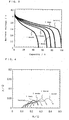
- Fig. 3 is a diagram showing discharge curves for batteries each having a different stored duration, which were detected in an example of the present invention.
- Fig. 4 is a Cole-Cole plot diagram showing the impedance characteristics of the same batteries.
- Fig. 5 is a diagram showing discharge curves for batteries each having the different number of charge/discharge cycles, which were detected in another example of the present invention.
- Fig. 6 is a block diagram showing the electrochemical model used in the same example.
- Fig. 7 is a diagram showing a discharge curve and the calculated values thereof in the first cycle measured in the same example.
- Fig. 8 is a diagram showing discharge curves and the calculated values thereof in the 200th cycle and the 400th cycle measured in the same example.
- the deterioration detecting method for an electrochemical device of the present invention is one for an electrochemical device comprising electrodes and an ion conductor, wherein an electrochemical characteristic of the electrochemical device is detected, and the detection value is then compared with a reference value indicating a standard electrochemical characteristic of the electrochemical device to estimate the degree of deterioration of the electrochemical device (hereinafter simply referred to as a "device").
- the electrochemical characteristic mentioned herein indicates a characteristic caused by an electrochemical reaction occurring within the electrochemical device, and such a characteristic includes the charge/discharge characteristic, the impedance characteristic, and the direct-current pulse characteristic and the like.
- the electrochemical characteristic of the device may be estimated using a model which expresses the electrochemical characteristic of the component (electrode and/or ion conductor) of the device by a parameter (hereinafter referred to as an "electrochemical parameter"). That is, a value of parameter indicating the electrochemical characteristic of the component, which is calculated from a detection value indicating the electrochemical characteristic of the detected device, may be compared with the reference value of the parameter indicating a standard electrochemical characteristic of the component to estimate the degree of deterioration of the device itself.
- the deterioration causes, in many cases, a decrease in ion concentration and mobility within the ion conductor and a reduction of the electrode active material itself.
- models representing the electrochemical characteristic of the device there are exemplified a potential model of the electrode, an electron transport model of the electrode, an ion transport model of the electrode, an ion transport model of the ion conductor, a model representing an electrochemical reaction occurring in the interface between the electrode and the ion conductor and the like. These models may be used separately or in arbitrary combination.
- the deterioration of the electrochemical device can be detected as described above, thereby determining the capacity of the device at that time (at the time of deterioration detection). Accordingly, if the output of the device is determined together with the deterioration detection, the remaining capacity of the device can be accurately detected.
- the deterioration detecting method and the remaining capacity detecting method as above are applicable, for example, to a charger. While an electrochemical characteristic of a device is detected during the charge, the degree of deterioration thereof can be detected, and thus the charge can be carried out correspondingly to the performance of the device. Therefore, this avoids an overcharging of the device, suppresses the cycle deterioration thereof, and thereby permits the sufficient realization of the performance thereof.
- discharging can be controlled correspondingly to the detected degree of deterioration of the device, thereby the service life of the device can be prolonged.
- the operation mode of an electric appliance can be forcedly controlled so as to reduce the load on the device.
- a recommended mode of discharging or that of operation of the electric appliances can be displayed to leave the selection of the mode to the user.
- Fig. 1 shows a schematic diagram illustrating a deterioration detecting apparatus used for implementing a deterioration detecting method for an electrochemical device in accordance with the present invention.
- This apparatus comprises: a detecting means 2 for detecting an electrochemical characteristic of an electrochemical device 1; a storage means 3 for storing a standard electrochemical characteristic of the electrochemical device 1; a comparing means 4 for comparing the standard electrochemical characteristic with the electrochemical characteristic of the device; and a deterioration determining means 5 for determining the degree of deterioration of the electrochemical device 1 based on the results calculated by the comparing means 4.
- the electrochemical characteristic of the electrochemical device to be detected for the deterioration determination is that caused by the electrochemical reaction occurring within the electrochemical device, and such characteristic can be recognized directly by the measurement of: the charge/discharge characteristic expressed by a charge curve, a discharge curve and the like; the impedance characteristic and the like.
- a reference value indicating the standard electrochemical characteristic used as the reference of the deterioration determination is previously stored in the storage means 3 comprising a magnetic recording device or the like.
- the reference value indicating the standard electrochemical characteristic is an initial value such as a value indicating the electrochemical characteristic of the device before deterioration.
- the reference value may also be a value indicating the electrochemical characteristic at a predetermined time before the detection of electrochemical characteristic or a value indicating the electrochemical characteristic detected predetermined charge/discharge cycles ago.
- the standard electrochemical characteristic is not necessarily the same item as that of the detected electrochemical characteristic.
- it may be a parameter constituting an electrochemical model expressing the detected electrochemical characteristic, that is, the value of the electrochemical parameter of the electrode and/or the ion conductor, which are components of the device.
- the electrochemical model represents the state of the electrochemical device or the component thereof by using a mathematical formula or a circuit based on the electrochemical parameter.
- a plurality of models such as a model representing the potential of the electrode, a model representing the electron transport of the electrode, a model representing the ion transport of the electrode, a model representing the ion transport of the ion conductor, and a model representing an electrochemical reaction occurring in the interface between the electrode and the ion conductor.
- the electrochemical parameter used for indicating the electrochemical characteristic of the component of the device may be, for example, the equilibrium potential E 0 of the electrode, the internal resistance R ohm of the electrode, the charge transfer resistance R ct due to the electrochemical reaction occurring in the interface between the electrode and the ion conductor, the ion transport resistance R mt or R ele in the electrode or the ion conductor, or the capacitance C dl of the electric double layer in the interface between the electrode and the ion conductor.
- the detecting means 2 detects the electrochemical characteristic of the electrochemical device 1. For example, a predetermined current signal or voltage signal is input to the electrochemical device 1, and the response current or voltage is detected.
- the comparing means 4 determines the degree of deterioration of the device 1 at the time of detection based on the detected electrochemical characteristic of the electrochemical device 1.
- the advance of deterioration of the device 1 causes a difference between the reference value indicating the standard electrochemical characteristic, which is stored in the storage means 3, and the detected value indicating the electrochemical characteristic of the device 1.
- the comparing means 4 detects this difference, thereby determining the degree of deterioration of the device 1.
- the comparing means 4 stores the electrochemical model as a mathematical formula or a relational table comprising a theoretical formula, an empirical approximate formula or the like. Then, the value of the constituting parameter is calculated based on the detected electrochemical characteristic. The comparing means 4 further compares the value of the parameter with the reference value of the parameter of the standard electrochemical characteristic.
- the parameter mentioned herein may include a single parameter and a combination of a plurality of parameters.
- the deterioration determining means 5 determines the degree of deterioration indicating how the electrochemical device has deteriorated based on the difference between the parameter value calculated by the comparing means 4 and the reference value.
- Fig. 2 shows a schematic diagram illustrating the configuration of a remaining capacity detecting apparatus of the present invention.
- the present apparatus comprises: a detecting means 2 for detecting an electrochemical characteristic of an electrochemical device 1; a storage means 3 for storing a standard electrochemical characteristic of the electrochemical device 1; a comparing means 4 for comparing the standard electrochemical characteristic with the electrochemical characteristic of the device; and a deterioration determining means 5 for determining the degree of deterioration of the electrochemical device 1 based on the results calculated by the comparing means 4.
- a detecting means 2 always monitors the output of the device 1.
- a remaining capacity estimating means 6 corrects the capacity of the device 1 based on the degree of deterioration of the device 1 calculated by the deterioration determining means 5. Further, it calculates the remaining capacity of the device 1 based on both the integrated value of the output current of the device 1 obtained by the signal from the detecting means 2 and the corrected capacity.
- a model representing the potential of an electrode in an electrochemical device represents the potential of the electrode in an unloaded state, that is, the potential of the electrode in the equilibrium state.
- Equation (1) Ox + ne - ⁇ Red wherein Ox is oxidized form for a substance, n is number of reaction electrons, e - is electron and Red is reduced form for a substance
- Equation (4) the amount of potential polarization of the electrode in a loaded state, i.e., the magnitude of the electrochemical polarization, is expressed by Equation (4): wherein E is potential, ⁇ is amount of potential polarization of the electrode in a loaded state, i is working current, R ohm is internal resistance of the electrode, R ct is electrode charge transfer resistance representing the electron transport, and R mt is mass transfer resistance due to the ion transport phenomenon.
- the electrode internal resistance R ohm represents the electron transport of the electrode, and is expressed by a model using the internal resistance of each electrode as a parameter.
- a model is expressed by further including the resistance values of the battery components such as a lead wire and an IC circuit.
- Equation (7) The exchange current density i 0 depends on the temperature, and is expressed by Equation (7):
- Each of R ohm , R ct , and R mt is determined by the material constituting the electrode. Further, in a battery, the internal resistance R ele of the ion conductor needs to be added within the parentheses in the right hand side of Equation (4).
- the parameter Ea is the activation energy of the electrode reaction shown in Equation (1).
- the activity is expressed by the product of a concentration and an activity coefficient.
- the diffusion coefficient D(T) at a temperature T is expressed by Equation (11): wherein E diff is activation energy of the diffusion coefficient.
- an electric double layer is generally formed in the interface between the electrode and the ion conductor.
- an electrochemical module (a model representing a potential model of the electrode, an electron transport model of the electrode, an ion transport model of the electrode, an ion transport model of the ion conductor, and a model representing an electrochemical reaction occurring in the interface between the electrode and the ion conductor) for the side reaction can be described similarly to the above-mentioned case.
- the electrode reaction shown in Equation (1) in each electrode can be expressed by the electrode reaction model of a combination of Equations (2) to (14) for each electrode. Accordingly, by solving these nonlinear simultaneous equations, the charging and discharging operation of the battery at a certain temperature can be reproduced.
- each parameter has a different value depending on the kind of the active material constituting the electrode, the kind of the electrolyte, the temperature within the battery, and the like.
- these equations can be used even when the deterioration has advanced owing to high temperature storing or charge/discharge cycles.
- the polarization rate increases in comparison with the potential in an unloaded state, and therefore, each resistance shown in Equation (4) strongly affects the charging and discharging operation.
- reaction formula other than the above-mentioned one can be used for reproducing the charging and discharging operation. Further, for reproducing the charging and discharging operation, in addition to the above-mentioned nonlinear simultaneous equations, each relational formula used may be replaced by an approximate formula, or a description by using an electric circuit equivalent to each relational formula may be constructed and solved by a circuit simulator.
- a deterioration detecting method in accordance with the present invention is described below using an electrochemical model applied to the case of a nickel-hydride secondary battery.
- the nickel-hydride secondary battery is a secondary battery which uses nickel hydroxide as the positive electrode material and hydrogen storage alloy as the negative electrode material.
- Aqueous KOH solution is widely used as the ion conductor, i.e., the electrolyte.
- the electrode reaction shown in Equation (1) is expressed by the following Equations (16) and (17): Nickel electrode NiOOH + e - + H + ⁇ Ni(OH) 2 Hydride electrode MH ⁇ M + H + + + e - wherein M is hydrogen storage alloy, and MH is hydride.
- a mobile ion species is a proton (H + )
- the electrochemical reactions of the nickel hydroxide and the hydrogen storage alloy depend on the activity of protons in each electrode.
- Equations (2) and (8) to (10) are expressed by the following Equations (18) to (21), respectively.
- E eq,Ni E 0,Ni + RT F
- c oxi is concentration of nickel oxyhydroxide in an unloaded state
- c Red concentration of nickel hydroxide in an unloaded state
- c ox + c Red c
- c ox (0, t) concentration of nickel oxyhydroxide on the electrode surface at time t
- c Red (0, t) concentration of nickel hydroxide on the electrode surface at time t
- c ox (0, t) + c Red (0, t) c
- D Ni is chemical diffusion coefficient of protons.
- the c ox (0, t) and c Red (0, t) can be obtained by setting an initial condition and a boundary condition into Equations (20) and (21).
- the electrode potential E eq, Ni, the electrode charge transfer resistance R ct, Ni of the redox reaction occurring in the interface between the electrode and the ion conductor, and the ion transport resistance R mt, Ni of the electrode can be obtained.
- the redox reaction of the nickel electrode can be described.
- the activity of the generated oxygen molecule is expressed by the product of the solubility constant Ks of oxygen into aqueous KOH solution and the partial pressure P O2 of oxygen.
- the i Ni, 3 denotes the proportion of the current used for the oxygen generating reaction in the total current.
- Equation (24) the amount of occurrence of the oxygen generating reaction can be found from the degree of polarization, and further, using Equation (25), the amount of consumption of the hydroxide ion in the ion conductor can be found from the current having flowed. Furthermore, Equation (27) provides the information of both the increase in the internal pressure of battery due to oxygen generation and the contribution to the oxygen generating reaction in overcharging.
- Equations (2) and (8) to (10) are expressed by the following Equations (28) to (31), respectively.
- the redox reaction in the hydrogen storage alloy electrode needs to be expressed in the activity rather than the concentration, which is different from the case of the nickel electrode.
- the a ox (0, t) and a Red (0, t) can be obtained by setting an initial condition and a boundary condition into Equations (30) and (31).
- the electrode potential E eq, MH, the electrode charge transfer resistance R ct, MH of the redox reaction occurring in the interface between the electrode and the ion conductor, and the ion transport resistance R mt, MH of the electrode can be obtained.
- the electrode resistance R ohm, MH and the electric double layer capacitance C dl, MH corresponding to the electron transport of the electrode can be described.
- Lithium ion secondary batteries each having a nominal capacity of 720 mAh and a nominal voltage of 3.6 V were stored in an atmosphere of 85 °C for one week, two weeks, three weeks, and one month, respectively for the purpose of advancing the deterioration thereof.
- a deterioration detecting method and a remaining capacity detecting method of the present invention were applied to these batteries to test the effectiveness thereof. The method of evaluation is described below.
- a constant current-constant voltage charging method which is the recommended method of charging of the present batteries, they were energized by a constant correct of 500 mA; and after the voltage reached 4.1 V, the voltage was maintained at the 4.1 V, and the charging was carried out for two hours in total.
- the remaining capacity of the batteries in this state was defined as 100%.
- the batteries having the remaining capacity of 100% were stored at a high temperature for the above-mentioned respective duration.
- each battery was discharged at a constant current of 144 mA in a thermostat at 20 °C until the voltage decreased to 3.0 V.
- Fig. 3 The behavior of voltage at that time is shown in Fig. 3.
- the vertical axis indicates the voltage
- the horizontal axis indicates the discharge capacity (normalized at 100%).
- a battery of the longer storing duration has the smaller battery capacity, which shows the advancing of deterioration due to the high temperature storing.
- the vertical axis indicates an imaginary number X
- the horizontal axis indicates a real number R.
- a circular arc was observed for each battery.
- the radius of each circular arc indicates the electrode charge transfer resistance R ct (a model representing the electrochemical reaction occurring in the interface between the electrode and the ion conductor). Accordingly, it has been confirmed that the R ct increases with the advance of deterioration.
- the deterioration of a battery can be detected based on the high frequency characteristic thereof.
- the duration of high temperature storing, the discharge capacity, the frequency used for calculation, the (R ohm + R ele ) and the degree of deterioration are shown in Table 1.
- the degree of deterioration is expressed by (100-(discharge capacity after storing)) (%) on the assumption that the 100% discharge capacity is 720 mAh.
- Duration of storing Discharge capacity (%) Frequency (Hz) R ohm + R ele ( ⁇ )
- the discharge capacity and the (R ohm + R ele ) of a battery change in proportion to the duration of high temperature storing. Accordingly, it is found that the degree of deterioration of the battery can be estimated from the (R ohm + R ele ).
- Remaining capacity (%) ((100 - (integrated current) /(discharge capacity estimated from degree of deterioration)) ⁇ 100
- the present invention can be used as a remaining capacity detecting method.
- a constant current charging method which is the recommended method of charging of the present batteries, they were energized by a constant correct of 120 mA; and when the charge capacity reached 120%, the charging was terminated. The remaining capacity of the batteries in this state was defined as 100%. After the charge, the batteries were discharged at a constant current of 240 mA until the voltage decreased to 1.0 V. The above-mentioned charging and discharging were carried out in a thermostat at 20 °C.
- Fig. 5 shows the discharge curves of these batteries.
- the vertical axis indicates the voltage
- the horizontal axis indicates the discharge capacity normalized at 100%.
- the discharge curve in the first cycle was reproduced.
- This reproduction was carried out by a simulation using, as the electrochemical model, an equivalent circuit involving the above-mentioned formulas as shown in Fig. 6.
- the fitting of the model was carried out by the least square method.
- Fig. 7 The calculated values obtained by the circuit simulator and the discharge curve obtained by the actual measurement are shown in Fig. 7.
- the vertical axis indicates the voltage
- the horizontal axis indicates the discharge capacity normalized at 100%.
- a mark ⁇ indicates a calculated value.
- the calculated values are identical with the discharge curve obtained by the measurement. Accordingly, it is understood that the calculated discharge curve reproduces the discharge curve obtained by the measurement in the first cycle.
- Ni /dT [V/K] -0.0014 -0.0014 Exchange current density of redox reaction of Ni electrode i 0, Ni [A/m 2 ] 0.0081 0.0068 Internal resistance of Ni electrode R ohm, Ni [ ⁇ ] 0.0063 0.0074 Charge transfer coefficient of redox reaction of Ni electrode ⁇ Ni 0.5 0.5 Activation energy of redox reaction of Ni electrode E a, Ni [J/mol] 30000 30000 Diffusion coefficient of protons in Ni electrode D Ni [m 2 /sec] 2.4 ⁇ 10 -13 0.82 ⁇ 10 -13 Activation energy of diffusion of protons in Ni electrode E diff, Ni [J/mol] 25000 25000 Electric double layer capacitance of Ni electrode C dl.
- Fig. 8 The calculated values obtained by the circuit simulator and the discharge curves obtained by the actual measurement are shown in Fig. 8.
- the vertical axis indicates the voltage
- the horizontal axis indicates the discharge capacity normalized at 100%.
- a mark ⁇ indicates a calculated value.
- the battery discharge capacity, the value R ele, and the value i 0, MH change linearly with the increase of the number of charge/discharge cycles. Accordingly, it is understood that by using an electrochemical model, the degree of deterioration of the battery can be estimated from the change in the values of the electrochemical parameters in the electrochemical model.
- the remaining capacity of the battery can be estimated by estimating the integrated current, for example, using an integrated current scheme during discharging.
- the R ele or the i 0, MH was used as an electrochemical parameter to be calculated by the fitting, however, another parameter may be used. Further, it is also possible that a circuit is constructed using a formula other than the above-mentioned one and that the calculation is carried out.
- the nonlinear simultaneous equations may be directly solved, and the formula of each model used in the electrochemical model may be replaced by an approximate formula thereby to solve it.
- a deterioration detecting method for an electrochemical device wherein the degree of deterioration of the electrochemical device can be found without the disassembling thereof. Further, it is possible to provide an accurate remaining capacity detecting method wherein the deterioration is considered.
Applications Claiming Priority (3)
| Application Number | Priority Date | Filing Date | Title |
|---|---|---|---|
| JP17306999 | 1999-06-18 | ||
| JP17306999A JP3669673B2 (ja) | 1999-06-18 | 1999-06-18 | 電気化学素子の劣化検出方法、残容量検出方法、並びにこれらを用いた充電器および放電制御装置 |
| PCT/JP2000/003823 WO2000079634A1 (en) | 1999-06-18 | 2000-06-12 | Method for detecting deterioration of electrochemical device, method for measuring remaining capacity, charger comprising them, and discharge controller |
Publications (2)
| Publication Number | Publication Date |
|---|---|
| EP1111705A1 true EP1111705A1 (de) | 2001-06-27 |
| EP1111705A4 EP1111705A4 (de) | 2005-03-16 |
Family
ID=15953641
Family Applications (1)
| Application Number | Title | Priority Date | Filing Date |
|---|---|---|---|
| EP00935657A Ceased EP1111705A4 (de) | 1999-06-18 | 2000-06-12 | Verrfahren zur erkennung von schäden an elektrochemischen vorrichtungen, verfahren zum messen der restkapazität, lader der diese verwendet und entladeregler |
Country Status (6)
| Country | Link |
|---|---|
| US (1) | US6480003B1 (de) |
| EP (1) | EP1111705A4 (de) |
| JP (1) | JP3669673B2 (de) |
| KR (1) | KR100440630B1 (de) |
| CN (1) | CN1172403C (de) |
| WO (1) | WO2000079634A1 (de) |
Cited By (5)
| Publication number | Priority date | Publication date | Assignee | Title |
|---|---|---|---|---|
| FR2841385A1 (fr) * | 2002-06-12 | 2003-12-26 | Toyota Motor Co Ltd | Dispositif de calcul du degre de deterioration et procede de calcul du degre de deterioration d'une batterie |
| CN102540091A (zh) * | 2011-12-02 | 2012-07-04 | 毛广甫 | 电池组的电池状态及数据检验方法 |
| WO2013178330A1 (de) * | 2012-05-26 | 2013-12-05 | Audi Ag | Verfahren und vorrichtung zum feststellen der tatsächlichen kapazität einer batterie |
| EP2775313A1 (de) * | 2013-03-06 | 2014-09-10 | IFP Energies nouvelles | Verfahren zur Bestimmung der Restkapazität einer Batterie |
| EP2339361A3 (de) * | 2009-12-25 | 2015-02-11 | Kabushiki Kaisha Toshiba | Batteriediagnosevorrichtung und -verfahren |
Families Citing this family (35)
| Publication number | Priority date | Publication date | Assignee | Title |
|---|---|---|---|---|
| US7227336B1 (en) * | 2002-04-02 | 2007-06-05 | Van Schalkwijk Walter A | Lithium ion rapid charging system and method |
| JP4061965B2 (ja) | 2002-05-14 | 2008-03-19 | ソニー株式会社 | 電池容量算出方法 |
| US6892148B2 (en) * | 2002-12-29 | 2005-05-10 | Texas Instruments Incorporated | Circuit and method for measurement of battery capacity fade |
| AT505966B1 (de) * | 2003-10-13 | 2012-11-15 | Cochlear Ltd | Verfahren und system zur batterieladekontrolle von hörimplantaten |
| JP2005312769A (ja) * | 2004-04-30 | 2005-11-10 | Olympus Corp | 受信装置および医療装置 |
| JP4560540B2 (ja) * | 2005-01-27 | 2010-10-13 | プライムアースEvエナジー株式会社 | 二次電池の充放電電気量推定方法および装置、二次電池の分極電圧推定方法および装置、並びに二次電池の残存容量推定方法および装置 |
| JP5220269B2 (ja) * | 2005-09-16 | 2013-06-26 | 古河電気工業株式会社 | 蓄電池の劣化状態・充電状態の検知方法及びその装置 |
| JP4872743B2 (ja) * | 2007-03-23 | 2012-02-08 | トヨタ自動車株式会社 | 二次電池の状態推定装置 |
| KR101097586B1 (ko) * | 2007-12-13 | 2011-12-22 | 파나소닉 주식회사 | 리튬 2차 전지의 수명 추정 방법과 열화 억제 방법, 수명 추정기와 열화 억제기, 그것을 이용한 전지 팩, 충전기 |
| US8115492B2 (en) * | 2008-01-25 | 2012-02-14 | Eveready Battery Company, Inc. | Fuel gauging system and method thereof |
| JP5044511B2 (ja) * | 2008-09-03 | 2012-10-10 | トヨタ自動車株式会社 | リチウムイオン電池の劣化判定方法、リチウムイオン電池の制御方法、リチウムイオン電池の劣化判定装置、リチウムイオン電池の制御装置及び車両 |
| US8179140B2 (en) * | 2009-07-10 | 2012-05-15 | Honda Motor Co., Ltd. | Method of estimating solid phase potential |
| DE102009042656A1 (de) | 2009-09-23 | 2011-03-24 | Bayerische Motoren Werke Aktiengesellschaft | Verfahren zur Steuerung bzw. Regelung mindestens eines den Alterungszustand eines elektrischen Energiespeichers beeinflussenden Betriebsparameters |
| JP2011076730A (ja) * | 2009-09-29 | 2011-04-14 | Sanyo Electric Co Ltd | 二次電池の評価方法 |
| US8467984B2 (en) * | 2009-09-30 | 2013-06-18 | Battelle Energy Alliance, Llc | Systems, methods and computer readable media for estimating capacity loss in rechargeable electrochemical cells |
| JP5633227B2 (ja) * | 2009-10-14 | 2014-12-03 | ソニー株式会社 | 電池パックおよび電池パックの劣化度検出方法 |
| US8346495B2 (en) | 2010-04-22 | 2013-01-01 | Battelle Energy Alliance, Llc | Systems, methods and computer-readable media to model kinetic performance of rechargeable electrochemical devices |
| US8521497B2 (en) * | 2010-06-03 | 2013-08-27 | Battelle Energy Alliance, Llc | Systems, methods and computer-readable media for modeling cell performance fade of rechargeable electrochemical devices |
| EP2583867B1 (de) * | 2010-06-18 | 2019-10-02 | Toyota Jidosha Kabushiki Kaisha | Vorrichtung zur bestimmung eines zersetzungsgrades |
| JP5071747B2 (ja) | 2011-01-13 | 2012-11-14 | 横河電機株式会社 | 二次電池の検査装置、二次電池の検査方法、二次電池の製造方法 |
| US20130297244A1 (en) * | 2011-02-28 | 2013-11-07 | Mitsubishi Heavy Industries, Ltd. | Secondary battery lifetime prediction apparatus, battery system and secondary battery lifetime prediction method |
| JP2014514582A (ja) * | 2011-05-11 | 2014-06-19 | イメジース テクノロジーズ アーペーエス | ソーラモジュールに関する故障診断のための方法 |
| KR101303596B1 (ko) * | 2011-09-05 | 2013-09-11 | 한국과학기술연구원 | 연료전지의 mea 열화의 실시간 측정 방법 및 측정 장치 |
| US9625532B2 (en) | 2011-10-10 | 2017-04-18 | Battelle Energy Alliance, Llc | Method, system, and computer-readable medium for determining performance characteristics of an object undergoing one or more arbitrary aging conditions |
| JP6094598B2 (ja) * | 2013-02-01 | 2017-03-15 | トヨタ自動車株式会社 | 電池システム |
| JP6148498B2 (ja) * | 2013-02-28 | 2017-06-14 | 積水化学工業株式会社 | 電池モデル構築方法及び蓄電池劣化推定装置 |
| US20140253725A1 (en) * | 2013-03-05 | 2014-09-11 | Lku Technology Ltd. | Enhanced Surveillance Camera |
| CN104241718B (zh) * | 2013-06-18 | 2016-10-05 | 联想(北京)有限公司 | 一种电池充电方法及电池充电设备 |
| WO2015075814A1 (ja) * | 2013-11-22 | 2015-05-28 | 株式会社日立製作所 | 二次電池の余寿命診断方法並びに余寿命診断装置及びこれを備えた電池システム |
| JP6409721B2 (ja) * | 2014-10-09 | 2018-10-24 | 株式会社デンソー | 電池状態推定装置 |
| JP6375215B2 (ja) * | 2014-11-28 | 2018-08-15 | プライムアースEvエナジー株式会社 | メモリ効果有無の判定方法及びメモリ効果有無の判定装置 |
| JP6160650B2 (ja) * | 2015-04-21 | 2017-07-12 | マツダ株式会社 | 電気二層式キャパシタの制御装置 |
| CN111527641A (zh) * | 2017-12-26 | 2020-08-11 | 松下知识产权经营株式会社 | 电池管理装置、电池系统、及车辆用电源系统 |
| JP7247543B2 (ja) * | 2018-11-22 | 2023-03-29 | トヨタ自動車株式会社 | 車両 |
| CN109239616A (zh) * | 2018-11-26 | 2019-01-18 | 重庆长安汽车股份有限公司 | 电池寿命衰减评估方法、装置及计算机可读存储介质 |
Citations (5)
| Publication number | Priority date | Publication date | Assignee | Title |
|---|---|---|---|---|
| JPH09134742A (ja) * | 1995-11-08 | 1997-05-20 | Furukawa Battery Co Ltd:The | 蓄電池の劣化判定方法 |
| US5703469A (en) * | 1995-06-05 | 1997-12-30 | Honda Giken Kogyo Kabushiki Kaisha | System for determining battery conditions |
| EP0887654A2 (de) * | 1997-06-24 | 1998-12-30 | Matsushita Electric Industrial Co., Ltd. | Verfahren zur Erfassung des Betriebszustandes wiederaufladbarer Batterien mit nicht wasserhaltigigem Elektrolyt |
| WO1999018448A1 (en) * | 1997-10-02 | 1999-04-15 | Guardian Link Limited | Electro-chemical deterioration test method and apparatus |
| EP1460709A1 (de) * | 2001-12-27 | 2004-09-22 | Panasonic EV Energy Co., Ltd. | Verfahren und einrichtung zur schätzung der verbleibenden kapazität einer sekundärzelle, batteriepacksystem und elektrisches fahrzeug |
Family Cites Families (7)
| Publication number | Priority date | Publication date | Assignee | Title |
|---|---|---|---|---|
| JPH0821434B2 (ja) | 1989-12-11 | 1996-03-04 | 新神戸電機株式会社 | 密閉形鉛蓄電池の劣化状態検知方法 |
| WO1997020225A1 (fr) * | 1994-05-31 | 1997-06-05 | Omron Corporation | Dispositif et procede d'estimation de la duree de vie restante d'une batterie |
| JP3379283B2 (ja) * | 1994-07-04 | 2003-02-24 | 株式会社日本自動車部品総合研究所 | バッテリ充電状態検出方法 |
| JPH08265984A (ja) | 1995-03-20 | 1996-10-11 | Sanyo Electric Co Ltd | 電源装置 |
| JP3182063B2 (ja) | 1995-10-17 | 2001-07-03 | 鬼怒川ゴム工業株式会社 | 現像装置のトナー供給ローラ |
| JP3402167B2 (ja) * | 1996-12-17 | 2003-04-28 | 松下電器産業株式会社 | 電池の状態解析装置 |
| JP3263336B2 (ja) * | 1997-06-24 | 2002-03-04 | 松下電器産業株式会社 | 二次電池の容量推測方法 |
-
1999
- 1999-06-18 JP JP17306999A patent/JP3669673B2/ja not_active Expired - Fee Related
-
2000
- 2000-06-12 CN CNB008010854A patent/CN1172403C/zh not_active Expired - Fee Related
- 2000-06-12 KR KR10-2001-7001683A patent/KR100440630B1/ko not_active IP Right Cessation
- 2000-06-12 US US09/762,974 patent/US6480003B1/en not_active Expired - Lifetime
- 2000-06-12 EP EP00935657A patent/EP1111705A4/de not_active Ceased
- 2000-06-12 WO PCT/JP2000/003823 patent/WO2000079634A1/ja active Application Filing
Patent Citations (5)
| Publication number | Priority date | Publication date | Assignee | Title |
|---|---|---|---|---|
| US5703469A (en) * | 1995-06-05 | 1997-12-30 | Honda Giken Kogyo Kabushiki Kaisha | System for determining battery conditions |
| JPH09134742A (ja) * | 1995-11-08 | 1997-05-20 | Furukawa Battery Co Ltd:The | 蓄電池の劣化判定方法 |
| EP0887654A2 (de) * | 1997-06-24 | 1998-12-30 | Matsushita Electric Industrial Co., Ltd. | Verfahren zur Erfassung des Betriebszustandes wiederaufladbarer Batterien mit nicht wasserhaltigigem Elektrolyt |
| WO1999018448A1 (en) * | 1997-10-02 | 1999-04-15 | Guardian Link Limited | Electro-chemical deterioration test method and apparatus |
| EP1460709A1 (de) * | 2001-12-27 | 2004-09-22 | Panasonic EV Energy Co., Ltd. | Verfahren und einrichtung zur schätzung der verbleibenden kapazität einer sekundärzelle, batteriepacksystem und elektrisches fahrzeug |
Non-Patent Citations (1)
| Title |
|---|
| See also references of WO0079634A1 * |
Cited By (10)
| Publication number | Priority date | Publication date | Assignee | Title |
|---|---|---|---|---|
| FR2841385A1 (fr) * | 2002-06-12 | 2003-12-26 | Toyota Motor Co Ltd | Dispositif de calcul du degre de deterioration et procede de calcul du degre de deterioration d'une batterie |
| EP2339361A3 (de) * | 2009-12-25 | 2015-02-11 | Kabushiki Kaisha Toshiba | Batteriediagnosevorrichtung und -verfahren |
| US9239363B2 (en) | 2009-12-25 | 2016-01-19 | Toshiba Corporation | Battery diagnosis device and method |
| CN102540091A (zh) * | 2011-12-02 | 2012-07-04 | 毛广甫 | 电池组的电池状态及数据检验方法 |
| WO2013178330A1 (de) * | 2012-05-26 | 2013-12-05 | Audi Ag | Verfahren und vorrichtung zum feststellen der tatsächlichen kapazität einer batterie |
| CN104335057A (zh) * | 2012-05-26 | 2015-02-04 | 奥迪股份公司 | 用于确定电池的实际容量的方法和设备 |
| US9400313B2 (en) | 2012-05-26 | 2016-07-26 | Audi Ag | Method and device for determining the actual capacity of a battery |
| CN104335057B (zh) * | 2012-05-26 | 2016-12-07 | 奥迪股份公司 | 用于确定电池的实际容量的方法和设备 |
| EP2775313A1 (de) * | 2013-03-06 | 2014-09-10 | IFP Energies nouvelles | Verfahren zur Bestimmung der Restkapazität einer Batterie |
| FR3003038A1 (fr) * | 2013-03-06 | 2014-09-12 | IFP Energies Nouvelles | Procede de determination de la capacite residuelle d'une batterie |
Also Published As
| Publication number | Publication date |
|---|---|
| JP2001006756A (ja) | 2001-01-12 |
| KR20010082079A (ko) | 2001-08-29 |
| EP1111705A4 (de) | 2005-03-16 |
| CN1172403C (zh) | 2004-10-20 |
| JP3669673B2 (ja) | 2005-07-13 |
| KR100440630B1 (ko) | 2004-07-21 |
| CN1314012A (zh) | 2001-09-19 |
| WO2000079634A1 (en) | 2000-12-28 |
| US6480003B1 (en) | 2002-11-12 |
Similar Documents
| Publication | Publication Date | Title |
|---|---|---|
| US6480003B1 (en) | Method for detecting deterioration of electrochemical device, method for measuring remaining capacity, charger comprising them, and discharge controller | |
| EP0987555B1 (de) | Verfahren und Vorrichtung zum Messen von Zustandsgrö en einer Batterie | |
| KR101487494B1 (ko) | 이차 전지의 파라미터 추정 장치 및 방법 | |
| AU2014205149B2 (en) | Methods and systems for recharging a battery | |
| TW588491B (en) | Battery charging method | |
| KR101454831B1 (ko) | 혼합 양극재를 포함하는 이차 전지의 출력 추정 장치 및 방법 | |
| EP3056918A1 (de) | Vorrichtung zur schätzung des zustandes einer hybridsekundärbatterie und verfahren dafür | |
| US10073146B2 (en) | Apparatus for estimating voltage of hybrid secondary battery and method thereof | |
| JPWO2011065009A1 (ja) | リチウムイオン二次電池の充電方法、及び電池パック | |
| WO2022134903A1 (zh) | 对锂离子电池进行活性恢复的方法以及锂离子电池 | |
| JP3705703B2 (ja) | 電気化学素子の制御方法 | |
| US6097176A (en) | Method for managing back-up power source | |
| JPH09178827A (ja) | 電池容量の残量検出装置 | |
| JP2000150000A (ja) | バックアップ電源の管理方法 | |
| EP0926758B1 (de) | Nickel-Metalhydrid Speicherbatterie für Hilfsstromversorgung | |
| Prakash et al. | Performance of Li-ion secondary batteries in low power, hybrid power supplies | |
| JP3875129B2 (ja) | 二次電池の充電方法及び装置 | |
| JPH09219221A (ja) | 電池の寿命推定方法およびその装置 | |
| CN116137354A (zh) | 一种电化学装置管理方法、系统、电池模组及电子设备 | |
| JP3340504B2 (ja) | 鉛蓄電池の劣化判定方法 | |
| CN116031513A (zh) | 电化学装置管理方法、电子设备、充电装置及存储介质 | |
| Ogata et al. | Battery research for telecommunications power supply systems at NTT | |
| CN116031505A (zh) | 电化学装置管理方法、电化学装置、电池模组及用电设备 | |
| KR101629755B1 (ko) | 이차 전지의 저온 출력 특성을 제어하기 위한 장치 및 그 방법 | |
| CN116472633A (zh) | 电化学装置管理方法、装置、充电装置、电池系统及介质 |
Legal Events
| Date | Code | Title | Description |
|---|---|---|---|
| PUAI | Public reference made under article 153(3) epc to a published international application that has entered the european phase |
Free format text: ORIGINAL CODE: 0009012 |
|
| 17P | Request for examination filed |
Effective date: 20010228 |
|
| AK | Designated contracting states |
Kind code of ref document: A1 Designated state(s): AT BE CH CY DE DK ES FI FR GB GR IE IT LI LU MC NL PT SE |
|
| PUAF | Information related to the publication of a search report (a3 document) modified or deleted |
Free format text: ORIGINAL CODE: 0009199SEPU |
|
| A4 | Supplementary search report drawn up and despatched |
Effective date: 20050131 |
|
| RIC1 | Information provided on ipc code assigned before grant |
Ipc: 7G 01R 31/36 B Ipc: 7H 01M 10/48 A |
|
| D17D | Deferred search report published (deleted) | ||
| DA4 | Supplementary search report drawn up and despatched (deleted) | ||
| RA4 | Supplementary search report drawn up and despatched (corrected) |
Effective date: 20050209 |
|
| 17Q | First examination report despatched |
Effective date: 20060906 |
|
| APBK | Appeal reference recorded |
Free format text: ORIGINAL CODE: EPIDOSNREFNE |
|
| APBN | Date of receipt of notice of appeal recorded |
Free format text: ORIGINAL CODE: EPIDOSNNOA2E |
|
| APBR | Date of receipt of statement of grounds of appeal recorded |
Free format text: ORIGINAL CODE: EPIDOSNNOA3E |
|
| APBR | Date of receipt of statement of grounds of appeal recorded |
Free format text: ORIGINAL CODE: EPIDOSNNOA3E |
|
| RAP1 | Party data changed (applicant data changed or rights of an application transferred) |
Owner name: PANASONIC CORPORATION |
|
| APAF | Appeal reference modified |
Free format text: ORIGINAL CODE: EPIDOSCREFNE |
|
| APAF | Appeal reference modified |
Free format text: ORIGINAL CODE: EPIDOSCREFNE |
|
| REG | Reference to a national code |
Ref country code: DE Ref legal event code: R003 |
|
| APBT | Appeal procedure closed |
Free format text: ORIGINAL CODE: EPIDOSNNOA9E |
|
| STAA | Information on the status of an ep patent application or granted ep patent |
Free format text: STATUS: THE APPLICATION HAS BEEN REFUSED |
|
| 18R | Application refused |
Effective date: 20120802 |