EP1111482B1 - Einstellungssteuerungsystem und -verfahren - Google Patents
Einstellungssteuerungsystem und -verfahren Download PDFInfo
- Publication number
- EP1111482B1 EP1111482B1 EP99940696A EP99940696A EP1111482B1 EP 1111482 B1 EP1111482 B1 EP 1111482B1 EP 99940696 A EP99940696 A EP 99940696A EP 99940696 A EP99940696 A EP 99940696A EP 1111482 B1 EP1111482 B1 EP 1111482B1
- Authority
- EP
- European Patent Office
- Prior art keywords
- control
- adjustment
- tolerable range
- storage means
- controlled variables
- Prior art date
- Legal status (The legal status is an assumption and is not a legal conclusion. Google has not performed a legal analysis and makes no representation as to the accuracy of the status listed.)
- Expired - Lifetime
Links
Images


Classifications
-
- G—PHYSICS
- G05—CONTROLLING; REGULATING
- G05B—CONTROL OR REGULATING SYSTEMS IN GENERAL; FUNCTIONAL ELEMENTS OF SUCH SYSTEMS; MONITORING OR TESTING ARRANGEMENTS FOR SUCH SYSTEMS OR ELEMENTS
- G05B13/00—Adaptive control systems, i.e. systems automatically adjusting themselves to have a performance which is optimum according to some preassigned criterion
- G05B13/02—Adaptive control systems, i.e. systems automatically adjusting themselves to have a performance which is optimum according to some preassigned criterion electric
- G05B13/0265—Adaptive control systems, i.e. systems automatically adjusting themselves to have a performance which is optimum according to some preassigned criterion electric the criterion being a learning criterion
Definitions
- the present invention relates to an adjustment control system such as an image quality maintaining adjustment means for an optical unit for reading an original image, a color laser printer, a color digital copying machine, etc., which is provided in an image forming apparatus such as an analog copying machine, a digital copying machine or a facsimile, as well as to an adjustment control method.
- an adjustment control system such as an image quality maintaining adjustment means for an optical unit for reading an original image, a color laser printer, a color digital copying machine, etc., which is provided in an image forming apparatus such as an analog copying machine, a digital copying machine or a facsimile, as well as to an adjustment control method.
- an analog copying machine comprises an optical unit for reading an image of an original placed on an original table of glass, and a process unit for forming a developer image on the basis of the image read by the optical unit and transferring it onto a recording medium such as a paper sheet.
- a resolving power of a finally obtained copy image varies depending on a resolving power for exposure on a photosensitive drum and a fidelity reproducibility of an electrophotographic process for the exposure image.
- the resolving power for exposure on the photosensitive drum varies depending on lens characteristics, a stop, mirror flatness, a position and an attitude of a lens and a mirror, relative positions of the original table and the photosensitive drum, etc.
- lens characteristics and stop it is desired that a uniform, high resolving power (MTF characteristics) be obtained over the entire image region of an image surface, the exposure light amount be sufficient, and the total path length be as short as possible.
- the lens characteristics and stop provide a wide tolerable range of resolving power, i.e. focal depth, so as to cancel an error in a relative position among an object surface (original surface), a lens and an image-formation surface (photosensitive drum).
- the lens has aberration (e.g. curvature of field). Furthermore, if a demand for decrease in manufacturing cost is considered, it is'difficult to meet all the requirements, and optimization needs to be achieved for a compromise.
- a lens optimized as mentioned above is so designed that an ideal (design-value) image-formation surface may be included within a focal depth.
- the relative position among the position/attitude of the lens and mirror, the original table and the photosensitive drum will vary due to a sum of variances in tolerance of many parts and in tolerance of assembly.
- the resolving power gradually decreases toward an end portion of the image-formation surface.
- the photosensitive drum surface serving as the image-formation surface is cylindrical, the variation in the exposure position leads to a variation in optical path length. Degradation in resolving power occurs due to a deviation from the focal position.
- the magnification varies and the resolving power deteriorates because of displacement of the same image point due to scanning (since slit exposure is performed, a latent image will blur unless the position on the photosensitive drum is uniform in association with the image points of the original in the slit width in scanning).
- the resolving power deteriorates more greatly at end portions of the image-formation surface.
- the resolving power may degrade due to such factors as the lens characteristics, e.g. focal depth or MTF characteristics, and positioning of the original table, mirror, lens and photosensitive drum. If the degradation due to these factors are to be improved by enhancing precision in machining the respective parts and precision of parts of the support member, the cost will increase.
- the input/output relationship is not independent.
- the same number of look-up tables as the number of orders of inputs/outputs are required.
- a large memory capacity is required and the identification work is very large.
- the relationship does not always coincide with the object apparatus, because of non-linear characteristics, an inter-object variance, reproducibility and a variation over time, etc.
- the adopted feedback control is feasible for cases where the identification is somewhat incomplete, but the number of times of convergence and control time for good/bad determination become greater by a degree corresponding to a difference from the identified apparatus.
- JP 6-110286 (A) discloses an adjustment control system according to the preamble of claim 1 and an adjustment control method according to the preamble of claim 2.
- US 5,079,691, US 3,634,664, US 5,682,309, US 4,763,627, JP 11-38737 (A), JP 62-72004 (A) and JP 7-281708 (A) disclose further adjustment control systems and methods, resp.
- the object of the present invention is to provide an adjustment control system and an adjustment control method capable of performing optimal adjustment and a control with high adjustment efficiency.
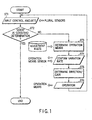
- FIG. 1 is a flow chart of an adaptive control with plural adjustment points according to an adjustment control system of the present invention.
- an entire control is executed by a CPU, etc.
- step ST1 controlled variables (in the following referred to as control amounts) are input from plural sensors (plural adjustment points). If all deviations of the control amounts are within tolerable ranges, the result is determined to be "good” in a good/bad determination step (ST2). Otherwise, the result is determined to be "bad”.
- step ST2 operation means is determined according to prestored adjustment rules for selecting operation means to be operated in association with a control amount pattern (ST3).
- a proportional control gain is found from a variation (ST4) of a control amount of interest (described in the adjustment rule), i.e. sensitivity, and an operation amount for decreasing a deviation (decreasing a deviation to zero in the case of proportional control) is calculated (ST5).
- the selected operation means is activated (ST6).
- steps ST3 to ST6 are repeated through step ST1 and the good/bad determination of step ST2, and deviations are converged. If convergence is completed (i.e. all deviations have fallen within tolerable ranges) and the determined result in step ST2 has become "good", the control is finished.
- an adjustment control system capable of easily achieving convergence can be realized without labor to collect quantitative data relating to values of all operation amount variables associated with all the control amount spaces.
- Quantitative knowledge is not provided in this technique.
- the technique is based on the sensitivity with which the selected operation means is actually operated in the situation. Thus, convergence does not become difficult in connection with the dependency of other operation means, an inter-object variance in characteristics of the object to be controlled, and the variance over time.
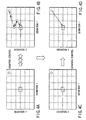
- FIG. 2A to FIG. 2F show an example of a converging step in the adaptive control described with reference to FIG. 1.
- FIG. 2A to FIG. 2F represent two control amount spaces in an example of a two-input/two-output system.
- the control amount deviations in the respective spaces are indicated by deviation 1 and deviation 2.
- a central intersection of orthogonal axes indicates an amount deviation 0 (zero).
- a rectangular region B around the central intersection indicates a tolerable deviation range, i.e. a tolerable range, of the respective deviations.
- Adjustment rule 1 ⁇ both deviations are out of the tolerable range ⁇ operation means 1 (off-set operation means). Attention is paid to a greater deviation, and the operation is determined based on sensitivity.
- Adjustment rule 2 ⁇ one of deviations is within the tolerable range ⁇ operation means 2 (gradient operation means). Attention is paid to a greater deviation, and the operation is determined based on sensitivity.
- FIG. 2A shows a case where initial values of both deviation 1 and deviation 2, which have been obtained by initial detection, are out of the tolerable range.
- the operation means 1 (off-set operation means) is selected. Since the sensitivity has not been confirmed, a test operation is performed with a predetermined operation amount, and detection is performed once again. A variation amount from the initial value of deviation 1, which is the deviation of interest, i.e. the sensitivity of deviation 1 as shown in FIG. 2B, is obtained.
- the operation amount for decreasing the deviation 1 to "0" is calculated. Based on the calculated operation amount, the operation means 1 is operated once again, and the deviation 1 is brought into the tolerable range, as shown in FIG. 2C, while deviation 2 is out of the tolerable range.
- the operation means 2 (gradient operation means) is selected. Since the sensitivity has not been confirmed, a test operation is performed with a predetermined operation amount, and detection is performed once again. A variation amount of deviation 2, which is the deviation of interest, i.e. the sensitivity of deviation 2 as shown in FIG. 2D, is obtained.
- the operation amount for decreasing the deviation 2 to "0" is calculated. Based on the calculated operation amount, the operation means 2 is operated once again, and both the deviations 1 and 2 have fallen out of the tolerable range (however, the deviations have come close to "0", i.e. have converged), as shown in FIG . 2E.
- the detection, determination, operation means selection, tests, sensitivity acquisition, operation amount determination and operations are repeated, and both deviations are converged into the tolerable range, as shown in FIG. 2F.
- the convergence can be carried out even if one operation amount variation depends on two control amount variables (i.e. not independent).
- control variation amounts 1 and 2 are given as qualitative knowledge with respect to operation variation amounts 1 and 2.
- the adjustment rules are then generated according to predetermined algorithms. Based on the adjustment rules, quantitative knowledge is given by means for successively detecting the sensitivity of the actual object and determining the operation amount. Thereby, the labor for development is reduced, and an adjustment control system matching with an inter-object variance or a variation over time can be obtained.
- the developing agent is consumed by the test development and the operation time aggravates long-time degradation of various parts and materials.
- the use by users is disabled (prohibited) during control.
- a decrease in the number of times of control amount detection and in the control time is desired.
- control time should be reduced in consideration of the number of adjustment steps.
- the system can reduce the labor for development and can match with an inter-object variance or a variation over time.
- the condition for the limitation to the number of times of control may not be satisfied.
- a controller is considered to be an inverse model of characteristics of a control object. Accordingly, a controller can be produced if input/output characteristics of the object, that is, the control amount relative to the operation amount, can be quantatively measured. For example, there are known methods wherein operation amounts relative to control amounts, as in a LUT (look-up table), are prestored in storage means and these amounts are referred to in accordance with actual control amounts in order to determine the operation amounts, or a similar table is prepared based on instructor data (case data).
- LUT look-up table
- the amount of acquired data units is expressed by (number of control amount variables) ⁇ ((number of divisions of control variation amounts) raised to the power of (number of control amount variables)), and a great deal of labor is required as the number of orders increases.
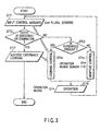
- FIG. 3 is a flow chart of a control in which the adaptive control and the learning control according to the adjustment control system of the present invention are combined.
- step ST11 control amounts are input from plural sensors (plural adjustment points). If all deviations of control amount variables are within tolerable ranges, the result is determined to be "good”. Otherwise, the result is determined to be "bad” (ST12).
- control amount pattern a position in the control amount deviation space is present in success experiences learnt at this time point. If there is the experience, the operation amount (variation amount for all operation means) of the success experience is adopted (ST14). Otherwise, the operation amount is determined based on the above-described adaptive control (ST15).
- the operation is further executed based on the operation amount of the success experience in step ST14 or the operation amount calculated in step ST15 (ST16).
- select means selected based on the adjustment rule in the adaptive control is operated in a test. Based on the obtained sensitivity, the operation is repeated to achieve convergence (steps ST11, ST12, ST13, ST15, ST16). Although a number of times of control is required, the convergence is completed ("good” in the good/bad determination in step ST12).
- step ST12 the control amount patterns at the respective time points including the initial deviation at the beginning of control and the test operation, and all the associated operation amount variation amounts relating to the respective control amount patterns up to the completion of convergence are stored (learnt) as success cases (ST17).
- the operation amount is thus determined by selection on the basis of the control patterns of the feedback control, in which the converging is ensured like the adaptive control, and of the learning control.
- an adjustment control system is provided, wherein the controller design labor is reduced, the convergence is ensured, and the number of times of control is decreased.
- FIGS. 4A to 4D show an example of a converging step using the adaptive control described with reference to FIGS. 2A to 2F and the learning control.
- FIG. 4A shows the initial deviation in the adaptive control
- FIG. 4C shows the initial deviation in the learning control.
- the adaptive control is selected. Convergence is gradually carried out in the adaptive control from the initial deviation shown in FIG. 4A, and at last a tolerable value as shown in FIG. 4B is reached. If the operation amount associated with the obtained control amount pattern has reproducibility relating to the object characteristics in the process reaching the tolerable range, it is possible to operate the learnt operation amount (plural operation means at the same time) and to bring the initial deviation shown in FIG. 4C to the tolerable range shown in FIG. 4D by a single operation.
- the adaptive control is switched and activated in the control amount pattern with no success experience, and a new success experience is attained by convergence.
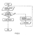
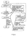
- FIG. 5 is a flow chart illustrating an operation of the entirety of the adjustment control system. The entire control is executed by a CPU, etc. Control amount detection and good/bad determination are performed. If a determination result is "bad”, an operation amount is determined, and an operation is executed. Control then returns to the control amount detection, and this process is repeated until a good/bad determination result becomes "good.” When a determination result "good” is obtained, an end process is performed.
- FIG. 6 is a flow chart illustrating a switching operation with learning in the adjustment control system. Specifically, when a control amount has been detected, the control amount is stored in primary storage means such as a RAM (control amounts and operation amounts from the start of control to the convergence for respective operations are stored). If the good/bad determination result is "bad", the control amount is compared with success experiences read out from secondary storage means such as a non-volatile RAM. If there is a coincident success experience, it is utilized. If there is no coincident success experience, the adaptive control is executed to determine an operation amount and this operation amount, too, is stored in the primary storage means.
- primary storage means such as a RAM (control amounts and operation amounts from the start of control to the convergence for respective operations are stored). If the good/bad determination result is "bad”, the control amount is compared with success experiences read out from secondary storage means such as a non-volatile RAM. If there is a coincident success experience, it is utilized. If there is no coincident success experience, the adaptive control is executed to determine
- the operation is executed, the control amount is detected once again, and the control amount is stored in the primary storage means. This process is repeated until the good/bad determination result becomes "good.” When the good/bad determination result has become "good,” the end process is performed and the operation amounts stored in the primary storage means up to the convergence are stored in the secondary storage means as success experiences.
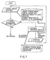
- FIG. 7 is a flow chart illustrating a function of a test operation (sensitivity measurement) in a case where there is no learning data in the adjustment control system. Specifically, when a control amount has been detected, the control amount is stored in primary storage means such as a RAM. If the good/bad determination result is "bad", the control amount is compared with success experiences read out from secondary storage means such as a non-volatile RAM. If there is no coincident success experience, the adaptive control is executed to first determine a test operation amount and this operation amount is stored in the primary storage means. Then, a test operation is executed.
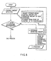
- FIG. 8 is a flow chart illustrating a function of a main operation in a case where there is no learning data in the adjustment control system. Specifically, after the test operation is executed, the control amount is detected and stored in the primary storage means. When the control amount has been determined to be "bad" in the good/bad determination, a main operation amount is determined on the basis of the sensitivity in the test operation, and this operation amount is stored in the primary storage means. Then, the operation is executed.
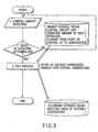
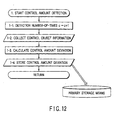
- FIG. 9 is a flow chart illustrating an operation of learning of success cases (history up to convergence) in the adjustment control system. Specifically, the control amount is detected and good/bad determination is performed, and this process is repeated until the good/bad determination result becomes "good.” When the good/bad determination result has become "good,” the end process is performed. In this case, the control amounts and operation amounts stored in the primary storage means from the start of control up to the convergence are read out and stored in the secondary storage means as success experiences. The success cases are managed over several generations.
- FIG. 10 is a flow chart illustrating a success experience utilizing operation in a case where there is learning data in the adjustment control system. Specifically, when a control amount has been detected, the control amount is stored in the primary storage means such as a RAM. When the control amount has been determined to be "bad" in the good/bad determination, it is compared with success experiences read out of the secondary storage means such as a non-volatile RAM. If there is a coincident success experience, an operation amount is determined based on this case data and the operation amount is stored in the primary storage means. Thus, the operation is executed.
- the primary storage means such as a RAM.
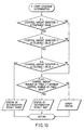
- FIG. 11 is a flow chart illustrating a learning data accumulation operation in the adjustment control system. Specifically, when a control amount has been detected, the control amount is stored in primary storage means such as a RAM. If the good/bad determination result is "bad", the control amount is compared with success experiences read out from secondary storage means such as a non-volatile RAM. If there is a coincident success experience, it is utilized. If there is no coincident success experience, the adaptive control is executed to determine an operation amount and this operation amount, too, is stored in the primary storage means.
- the operation is executed, and the control amount is detected once again.
- the control amount is stored in primary storage means. If the good/bad determination result is "bad”, the adaptive control is executed to once again determine an operation amount and this operation amount, too, is stored in the primary storage means.
- the adaptive control is repeated until the good/bad determination result becomes "good.”
- the good/bad determination result has become "good,” the end process is performed.
- the control amounts and operation amounts stored in the primary storage means from the start of control up to the convergence are read out and stored in the secondary storage means as success experiences.
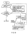
- FIG. 12 is a flow chart illustrating an operation of control amount detection in the adjustment control system. To begin with, the number of times of detection in the operation is counted, and information from plural control objects is collected. Then, deviations of control amounts are calculated, and the plural control amount deviations are stored in the primary storage means such as a RAM.
- the primary storage means such as a RAM.
- FIG. 13 is a flow chart illustrating the good/bad determination operation in the adjustment control system.
- plural control amount deviations at the time the control amounts have been detected are compared with tolerable values. For example, when the plural control amount deviations are control amount deviations 1, 2, ⁇ , n, it is determined whether control amount deviation 1 is less than, or equal to, tolerable value 1. Then, it is determined whether control amount deviation 2 is less than, or equal to, tolerable value 2, and it is determined whether control amount deviation n is less than, or equal to, tolerable value n. If all control amount deviations are less than, or equal to, the respective tolerable values, a good/bad determination result is "good,” and status "good” is issued.
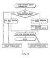
- FIG. 14 is a flow chart illustrating an operation amount determination function in the adjustment control system.
- the operation amount determination method is selected.
- Plural control amount deviations based on the detected control amount are compared with success cases stored in the secondary storage means, and it is checked whether there is a coincident case. If there is a coincident case, this success case is adopted to determine the operation amount. If there is no coincident case, the adaptive control is executed and the operation means is selected. In addition, the operation amount is calculated and stored in the primary storage means.
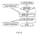
- FIG. 15 is a flow chart illustrating an end process operation in the adjustment control system. If the good/bad determination result "good” is obtained, history data stored in the primary storage means is arranged as a success case and this success case is stored in the secondary storage means.
- control system ensuring convergence is obtained.
- the control system can match with an inter-object variance and a variation over time in control system characteristics for success case learning in the adjustment object system.
- both a convergence-ensured control such as an adaptive control
- a learning control is used in combination.
- the sensitivity is examined in succession to determine the operation amount for convergence.
- the convergence is completed, a successful experience is learnt and, in a similar situation, the learnt knowledge is utilized to perform operations.
- the number of times of operations for convergence can be reduced.
Landscapes
- Engineering & Computer Science (AREA)
- Artificial Intelligence (AREA)
- Health & Medical Sciences (AREA)
- Computer Vision & Pattern Recognition (AREA)
- Evolutionary Computation (AREA)
- Medical Informatics (AREA)
- Software Systems (AREA)
- Physics & Mathematics (AREA)
- General Physics & Mathematics (AREA)
- Automation & Control Theory (AREA)
- Feedback Control In General (AREA)
- Control Or Security For Electrophotography (AREA)
Claims (2)
- Einstellungssteuerungssystem mit
einem ersten Speichermittel zum Speichern von Fällen einer Mehrzahl von gesteuerten Variablen, die eingestellt und gesteuert sind, um in einen vorbestimmten tolerierbaren Bereich zu fallen;
einem Detektionsmittel zum Detektieren einer Mehrzahl von gesteuerten Variablen;
einem Bestimmungsmittel zum Bestimmen, ob jede der gesteuerten Variablen, die von dem Detektionsmittel detektiert worden sind, in einen vorbestimmten tolerierbaren Bereich fällt;
einem Beurteilungsmittel zum Beurteilen, wenn durch das Bestimmungsmittel bestimmt worden ist, dass mindestens eine der mehreren gesteuerten Variablen außerhalb des vorbestimmten tolerierbaren Bereichs liegt, ob ein Fall vorliegt, bei dem die Einstellungssteuerung auf den vorbestimmten tolerierbaren Bereich von den mehreren gesteuerten Variablen erreicht worden ist, die in dem ersten Speichermittel gespeichert sind; und
einem ersten Steuermittel zum Steuern, wenn das Vorhandensein des Falls der Einstellungssteuerung durch das Beurteilungsmittel beurteilt worden ist, der Einstellung, um auf der Basis des Falls jede der detektierten gesteuerten Variablen in den vorbestimmten tolerierbaren Bereich zu bringen, gekennzeichnet durch
ein erstes Betriebsmittel zum Bestimmen und Anwenden von Testbetriebswerten zur Messung der Empfindlichkeit, basierend auf jeder detektierten gesteuerten Variablen, wenn das Fehlen des Falls der Einstellungssteuerung durch das Beurteilungsmittel beurteilt worden ist;
ein zweites Betriebsmittel zum Bestimmen von Betriebswerten von jeder detektierten gesteuerten Variablen, basierend auf der Empfindlichkeit, die durch die Testoperationen gemessen worden sind, die von dem ersten Betriebsmittel durchgeführt worden sind, und Durchführen wiederholter Operationen bis jede detektierte gesteuerte Variable in den vorbestimmten tolerierbaren Bereich fallen kann;
ein zweites Speichermittel zum Speichern der Betriebswerte, die von dem ersten Betriebsmittel angewendet werden, und der mehreren gesteuerten Variablen, sowie der Betriebswerte, die wiederholt durch das zweite Betriebsmittel angewendet werden, und der mehreren gesteuerten Variablen; und
ein zweites Steuerungsmittel zum Speichern, wenn jede gesteuerte Variable in den vorbestimmten tolerierbaren Bereich gefallen ist, durch den Betrieb des zweiten Betriebsmittels, der Betriebswerte und der mehreren gesteuerten Variablen, die in dem zweiten Speichermittel gespeichert sind, in das erste Speichermittel, als Fälle der Einstellungssteuerung. - Einstellungssteuerungsverfahren mit den Schritten:Speichern von Fällen einer Mehrzahl von gesteuerten Variablen, die eingestellt und gesteuert sind, um in einen vorbestimmten tolerierbaren Bereich zu fallen, in einem ersten Speichermittel;Detektieren (ST 11) einer Mehrzahl von gesteuerten Variablen;Bestimmen (ST 12), ob jede der detektierten gesteuerten Variablen in einen vorbestimmten tolerierbaren Bereich fällt;Beurteilen (ST 13), wenn durch die Bestimmung bestimmt worden ist, dass mindestens eine der mehreren gesteuerten Variablen außerhalb des vorbestimmten tolerierbaren Bereichs liegt, ob unter den mehreren gesteuerten Variablen, die in dem ersten Speichermittel gespeichert sind, ein Fall vorliegt, der eingestellt und gesteuert worden ist, um in den vorbestimmten tolerierbaren Bereich zu fallen; undSteuern (ST 14), wenn das Vorhandensein des Falls der Einstellungssteuerung durch die Beurteilung beurteilt worden ist, der Einstellung, um auf der Basis des Falls jede der detektierten gesteuerten Variablen in den vorbestimmten tolerierbaren Bereich zu bringen; gekennzeichnet durchBestimmen und Anwenden (ST 15, ST 3, ST 4) von Testbetriebswerten zur Messung der Empfindlichkeit, basierend auf jeder detektierten gesteuerten Variablen, wenn das Fehlen des Falls der Einstellungssteuerung durch die Beurteilung beurteilt worden ist;Bestimmen (ST 15, ST 5) von Betriebswerten von jeder detektierten gesteuerten Variablen, basierend auf der Empfindlichkeit, die von den Testoperationen gemessen worden ist, und Durchführen (ST 16, ST 11 - ST 16) wiederholter Operationen bis jede detektierte gesteuerte Variable in den vorbestimmten tolerierbaren Bereich fallen kann;Speichern der angewendeten Betriebswerte und der mehreren gesteuerten Variablen in dem zweiten Speichermittel, sowie der wiederholt angewendeten Betriebswerte und der mehreren gesteuerten Variablen; undSpeichern (ST 17), wenn jede gesteuerte Variable in den vorbestimmten tolerierbaren Bereich durch die Operation gefallen ist, der Betriebswerte und der mehreren gesteuerten Variablen, die in dem zweiten Speichermittel gespeichert sind, in dem ersten Speichermittel, als Fälle der Einstellungssteuerung.
Applications Claiming Priority (3)
| Application Number | Priority Date | Filing Date | Title |
|---|---|---|---|
| JP10252678A JP2000089525A (ja) | 1998-09-07 | 1998-09-07 | 調整制御システム |
| JP25267898 | 1998-09-07 | ||
| PCT/JP1999/004842 WO2000014609A1 (fr) | 1998-09-07 | 1999-09-07 | Systeme de commande d'ajustement |
Publications (3)
| Publication Number | Publication Date |
|---|---|
| EP1111482A1 EP1111482A1 (de) | 2001-06-27 |
| EP1111482A4 EP1111482A4 (de) | 2001-12-05 |
| EP1111482B1 true EP1111482B1 (de) | 2003-12-03 |
Family
ID=17240726
Family Applications (1)
| Application Number | Title | Priority Date | Filing Date |
|---|---|---|---|
| EP99940696A Expired - Lifetime EP1111482B1 (de) | 1998-09-07 | 1999-09-07 | Einstellungssteuerungsystem und -verfahren |
Country Status (6)
| Country | Link |
|---|---|
| US (1) | US6591147B2 (de) |
| EP (1) | EP1111482B1 (de) |
| JP (1) | JP2000089525A (de) |
| CN (1) | CN1122882C (de) |
| DE (1) | DE69913359D1 (de) |
| WO (1) | WO2000014609A1 (de) |
Families Citing this family (11)
| Publication number | Priority date | Publication date | Assignee | Title |
|---|---|---|---|---|
| DE10146826B4 (de) | 2001-09-19 | 2004-11-25 | Deutsches Zentrum für Luft- und Raumfahrt e.V. | Verfahren zur Analyse von Silizium-Germanium-Legierungen und Vorrichtung zur Herstellung von Halbleiterschichtstrukturen mit Silizium-Germanium-Legierungsschichten |
| US7389152B2 (en) * | 2004-06-04 | 2008-06-17 | Scan-Optics Inc. | High speed image scanner |
| WO2006046224A2 (en) * | 2004-10-28 | 2006-05-04 | Hewlett-Packard Development Company, L.P. | Dot gain and color linearization dual calibration |
| JP4170315B2 (ja) * | 2005-05-30 | 2008-10-22 | インターナショナル・ビジネス・マシーンズ・コーポレーション | 異常判断装置、制御方法、自動車およびプログラム |
| JP4997740B2 (ja) * | 2005-11-02 | 2012-08-08 | オムロン株式会社 | 生産管理装置、生産管理方法、生産管理システム、生産管理プログラム、および記録媒体 |
| DE102010001781A1 (de) * | 2010-02-10 | 2011-08-11 | Siemens Aktiengesellschaft, 80333 | Verfahren zur Bewegung eines Maschinenelements einer Maschine aus der Automatisierungstechnik und Steuereinrichtung |
| US8406919B1 (en) | 2010-03-12 | 2013-03-26 | Key Technology, Inc. | Quality regulating apparatus and method |
| US9488974B2 (en) * | 2010-08-17 | 2016-11-08 | Massachusetts Institute Of Technology | Method and apparatus for pulse-modulated feedback control |
| JP5870970B2 (ja) * | 2013-06-24 | 2016-03-01 | コニカミノルタ株式会社 | 画像形成装置、制御装置及び画像形成システム |
| JP6536978B1 (ja) * | 2018-03-15 | 2019-07-03 | オムロン株式会社 | 学習装置、学習方法、及びそのプログラム |
| CN114607702B (zh) * | 2022-03-15 | 2023-02-24 | 珠海格力电器股份有限公司 | 磁悬浮系统的控制方法、装置、磁悬浮系统和存储介质 |
Family Cites Families (14)
| Publication number | Priority date | Publication date | Assignee | Title |
|---|---|---|---|---|
| US3634664A (en) * | 1969-04-04 | 1972-01-11 | Bendix Corp | Adaptive and manual control system for machine tool |
| US4763627A (en) * | 1985-07-02 | 1988-08-16 | Japan Electronic Control Systems, Co., Ltd. | Learning and control apparatus for electronically controlled internal combustion engine |
| JPS6272004A (ja) * | 1985-09-26 | 1987-04-02 | Toshiba Corp | ロボツト |
| DE3816520A1 (de) * | 1988-05-14 | 1989-11-23 | Bosch Gmbh Robert | Regelverfahren und -vorrichtung, insbesondere lambdaregelung |
| JP3036143B2 (ja) * | 1991-09-02 | 2000-04-24 | 三菱電機株式会社 | 数値制御装置 |
| JPH06110286A (ja) * | 1992-09-24 | 1994-04-22 | Toshiba Corp | 画像形成装置 |
| US5526293A (en) * | 1993-12-17 | 1996-06-11 | Texas Instruments Inc. | System and method for controlling semiconductor wafer processing |
| JP2937007B2 (ja) * | 1994-04-12 | 1999-08-23 | 株式会社デンソー | オートチューニングコントローラ |
| US5457625A (en) * | 1994-04-13 | 1995-10-10 | The M. W. Kellogg Company | Maximizing process production rates using permanent constraints |
| US5610843A (en) * | 1995-03-01 | 1997-03-11 | Sri International | Methods and apparatuses for multi input/multi output control systems |
| US5682309A (en) * | 1995-04-28 | 1997-10-28 | Exxon Chemical Patents Inc. | Feedback method for controlling non-linear processes |
| JP3658075B2 (ja) | 1996-02-09 | 2005-06-08 | キヤノン株式会社 | 画像形成装置 |
| JPH1138737A (ja) * | 1997-07-15 | 1999-02-12 | Toshiba Corp | 光学ユニットの調整方法および調整装置 |
| US6393387B1 (en) * | 1998-03-06 | 2002-05-21 | Perot Systems Corporation | System and method for model mining complex information technology systems |
-
1998
- 1998-09-07 JP JP10252678A patent/JP2000089525A/ja active Pending
-
1999
- 1999-09-07 DE DE69913359T patent/DE69913359D1/de not_active Expired - Lifetime
- 1999-09-07 EP EP99940696A patent/EP1111482B1/de not_active Expired - Lifetime
- 1999-09-07 WO PCT/JP1999/004842 patent/WO2000014609A1/ja not_active Ceased
- 1999-09-07 CN CN99118527.7A patent/CN1122882C/zh not_active Expired - Fee Related
-
2001
- 2001-03-07 US US09/799,526 patent/US6591147B2/en not_active Expired - Fee Related
Also Published As
| Publication number | Publication date |
|---|---|
| CN1122882C (zh) | 2003-10-01 |
| WO2000014609A1 (fr) | 2000-03-16 |
| CN1248733A (zh) | 2000-03-29 |
| EP1111482A1 (de) | 2001-06-27 |
| US6591147B2 (en) | 2003-07-08 |
| US20010044662A1 (en) | 2001-11-22 |
| JP2000089525A (ja) | 2000-03-31 |
| DE69913359D1 (de) | 2004-01-15 |
| EP1111482A4 (de) | 2001-12-05 |
Similar Documents
| Publication | Publication Date | Title |
|---|---|---|
| EP1111482B1 (de) | Einstellungssteuerungsystem und -verfahren | |
| US7058325B2 (en) | Systems and methods for correcting banding defects using feedback and/or feedforward control | |
| US6268903B1 (en) | Method of adjusting projection optical apparatus | |
| US6806896B2 (en) | Method of shifting an image or paper to reduce show through in duplex printing | |
| US7800799B2 (en) | Color shift correcting apparatus and method, image forming apparatus, color shift correcting program and recording medium | |
| US4879576A (en) | Exposure control device and method | |
| US20060244937A1 (en) | Method for exposing a semiconductor wafer | |
| CN100378600C (zh) | 成像装置的控制方法 | |
| JP2007003707A (ja) | 画像形成装置及びプログラム | |
| EP2541331B1 (de) | Bilderstellungsvorrichtung mit einem Steuerungsverfahren für diese Vorrichtung | |
| US20040175195A1 (en) | Image forming apparatus and image forming method | |
| EP1273443A1 (de) | Unterstützungseinheit, Unterstützungssystem und Unterstützungsverfahren für eine Druckvorrichtung | |
| EP0940773A2 (de) | Bilverarbeitungsverfahren und -vorrichtung | |
| JP2000227684A (ja) | 画像形成装置及びその制御方法 | |
| JP2020194130A (ja) | 画像形成装置、カートリッジ、画像形成システム及び記憶媒体 | |
| US6853816B2 (en) | Image forming apparatus and method for adjusting magnification of image information | |
| JPH0651599A (ja) | 画質制御装置 | |
| JP3679565B2 (ja) | 書込ヘッド焦点位置調整方法及び画像形成装置 | |
| JPH10133519A (ja) | ディジタル複写機 | |
| JPH03100573A (ja) | 画像形成装置 | |
| US20050286086A1 (en) | Image output apparatus, output image control method, and output image control program | |
| KR100610260B1 (ko) | 화상형성장치 및 화상형성장치의 제어방법 | |
| JP3170272B2 (ja) | 画像濃度制御方法 | |
| JP2007093761A (ja) | 画像形成装置、画像形成装置の制御方法、プログラム及びコンピュータ読取可能記録媒体 | |
| JP3520897B2 (ja) | 画像形成装置 |
Legal Events
| Date | Code | Title | Description |
|---|---|---|---|
| PUAI | Public reference made under article 153(3) epc to a published international application that has entered the european phase |
Free format text: ORIGINAL CODE: 0009012 |
|
| 17P | Request for examination filed |
Effective date: 20010320 |
|
| AK | Designated contracting states |
Kind code of ref document: A1 Designated state(s): DE FR GB |
|
| A4 | Supplementary search report drawn up and despatched |
Effective date: 20011024 |
|
| AK | Designated contracting states |
Kind code of ref document: A4 Designated state(s): DE FR GB |
|
| 17Q | First examination report despatched |
Effective date: 20020325 |
|
| GRAH | Despatch of communication of intention to grant a patent |
Free format text: ORIGINAL CODE: EPIDOS IGRA |
|
| GRAS | Grant fee paid |
Free format text: ORIGINAL CODE: EPIDOSNIGR3 |
|
| GRAA | (expected) grant |
Free format text: ORIGINAL CODE: 0009210 |
|
| AK | Designated contracting states |
Kind code of ref document: B1 Designated state(s): DE FR GB |
|
| PG25 | Lapsed in a contracting state [announced via postgrant information from national office to epo] |
Ref country code: FR Free format text: LAPSE BECAUSE OF FAILURE TO SUBMIT A TRANSLATION OF THE DESCRIPTION OR TO PAY THE FEE WITHIN THE PRESCRIBED TIME-LIMIT Effective date: 20031203 |
|
| REG | Reference to a national code |
Ref country code: GB Ref legal event code: FG4D |
|
| REF | Corresponds to: |
Ref document number: 69913359 Country of ref document: DE Date of ref document: 20040115 Kind code of ref document: P |
|
| PG25 | Lapsed in a contracting state [announced via postgrant information from national office to epo] |
Ref country code: DE Free format text: LAPSE BECAUSE OF FAILURE TO SUBMIT A TRANSLATION OF THE DESCRIPTION OR TO PAY THE FEE WITHIN THE PRESCRIBED TIME-LIMIT Effective date: 20040304 |
|
| PLBE | No opposition filed within time limit |
Free format text: ORIGINAL CODE: 0009261 |
|
| STAA | Information on the status of an ep patent application or granted ep patent |
Free format text: STATUS: NO OPPOSITION FILED WITHIN TIME LIMIT |
|
| 26N | No opposition filed |
Effective date: 20040906 |
|
| EN | Fr: translation not filed | ||
| PGFP | Annual fee paid to national office [announced via postgrant information from national office to epo] |
Ref country code: GB Payment date: 20050907 Year of fee payment: 7 |
|
| GBPC | Gb: european patent ceased through non-payment of renewal fee |
Effective date: 20060907 |
|
| PG25 | Lapsed in a contracting state [announced via postgrant information from national office to epo] |
Ref country code: GB Free format text: LAPSE BECAUSE OF NON-PAYMENT OF DUE FEES Effective date: 20060907 |