EP1106908B1 - Fahrzeugscheiwerfer und Fahrzeug, welches mit diesem ausgestattet ist - Google Patents
Fahrzeugscheiwerfer und Fahrzeug, welches mit diesem ausgestattet ist Download PDFInfo
- Publication number
- EP1106908B1 EP1106908B1 EP00126309A EP00126309A EP1106908B1 EP 1106908 B1 EP1106908 B1 EP 1106908B1 EP 00126309 A EP00126309 A EP 00126309A EP 00126309 A EP00126309 A EP 00126309A EP 1106908 B1 EP1106908 B1 EP 1106908B1
- Authority
- EP
- European Patent Office
- Prior art keywords
- light
- reflector
- distribution pattern
- reflective surface
- vehicular headlamp
- Prior art date
- Legal status (The legal status is an assumption and is not a legal conclusion. Google has not performed a legal analysis and makes no representation as to the accuracy of the status listed.)
- Expired - Lifetime
Links
Images


Classifications
-
- B—PERFORMING OPERATIONS; TRANSPORTING
- B60—VEHICLES IN GENERAL
- B60Q—ARRANGEMENT OF SIGNALLING OR LIGHTING DEVICES, THE MOUNTING OR SUPPORTING THEREOF OR CIRCUITS THEREFOR, FOR VEHICLES IN GENERAL
- B60Q1/00—Arrangement of optical signalling or lighting devices, the mounting or supporting thereof or circuits therefor
- B60Q1/02—Arrangement of optical signalling or lighting devices, the mounting or supporting thereof or circuits therefor the devices being primarily intended to illuminate the way ahead or to illuminate other areas of way or environments
- B60Q1/04—Arrangement of optical signalling or lighting devices, the mounting or supporting thereof or circuits therefor the devices being primarily intended to illuminate the way ahead or to illuminate other areas of way or environments the devices being headlights
- B60Q1/06—Arrangement of optical signalling or lighting devices, the mounting or supporting thereof or circuits therefor the devices being primarily intended to illuminate the way ahead or to illuminate other areas of way or environments the devices being headlights adjustable, e.g. remotely-controlled from inside vehicle
- B60Q1/08—Arrangement of optical signalling or lighting devices, the mounting or supporting thereof or circuits therefor the devices being primarily intended to illuminate the way ahead or to illuminate other areas of way or environments the devices being headlights adjustable, e.g. remotely-controlled from inside vehicle automatically
- B60Q1/12—Arrangement of optical signalling or lighting devices, the mounting or supporting thereof or circuits therefor the devices being primarily intended to illuminate the way ahead or to illuminate other areas of way or environments the devices being headlights adjustable, e.g. remotely-controlled from inside vehicle automatically due to steering position
-
- F—MECHANICAL ENGINEERING; LIGHTING; HEATING; WEAPONS; BLASTING
- F21—LIGHTING
- F21S—NON-PORTABLE LIGHTING DEVICES; SYSTEMS THEREOF; VEHICLE LIGHTING DEVICES SPECIALLY ADAPTED FOR VEHICLE EXTERIORS
- F21S41/00—Illuminating devices specially adapted for vehicle exteriors, e.g. headlamps
- F21S41/10—Illuminating devices specially adapted for vehicle exteriors, e.g. headlamps characterised by the light source
- F21S41/14—Illuminating devices specially adapted for vehicle exteriors, e.g. headlamps characterised by the light source characterised by the type of light source
- F21S41/162—Incandescent light sources, e.g. filament or halogen lamps
-
- F—MECHANICAL ENGINEERING; LIGHTING; HEATING; WEAPONS; BLASTING
- F21—LIGHTING
- F21S—NON-PORTABLE LIGHTING DEVICES; SYSTEMS THEREOF; VEHICLE LIGHTING DEVICES SPECIALLY ADAPTED FOR VEHICLE EXTERIORS
- F21S41/00—Illuminating devices specially adapted for vehicle exteriors, e.g. headlamps
- F21S41/30—Illuminating devices specially adapted for vehicle exteriors, e.g. headlamps characterised by reflectors
- F21S41/32—Optical layout thereof
- F21S41/33—Multi-surface reflectors, e.g. reflectors with facets or reflectors with portions of different curvature
- F21S41/334—Multi-surface reflectors, e.g. reflectors with facets or reflectors with portions of different curvature the reflector consisting of patch like sectors
-
- F—MECHANICAL ENGINEERING; LIGHTING; HEATING; WEAPONS; BLASTING
- F21—LIGHTING
- F21S—NON-PORTABLE LIGHTING DEVICES; SYSTEMS THEREOF; VEHICLE LIGHTING DEVICES SPECIALLY ADAPTED FOR VEHICLE EXTERIORS
- F21S41/00—Illuminating devices specially adapted for vehicle exteriors, e.g. headlamps
- F21S41/30—Illuminating devices specially adapted for vehicle exteriors, e.g. headlamps characterised by reflectors
- F21S41/32—Optical layout thereof
- F21S41/36—Combinations of two or more separate reflectors
- F21S41/365—Combinations of two or more separate reflectors successively reflecting the light
-
- F—MECHANICAL ENGINEERING; LIGHTING; HEATING; WEAPONS; BLASTING
- F21—LIGHTING
- F21S—NON-PORTABLE LIGHTING DEVICES; SYSTEMS THEREOF; VEHICLE LIGHTING DEVICES SPECIALLY ADAPTED FOR VEHICLE EXTERIORS
- F21S41/00—Illuminating devices specially adapted for vehicle exteriors, e.g. headlamps
- F21S41/30—Illuminating devices specially adapted for vehicle exteriors, e.g. headlamps characterised by reflectors
- F21S41/39—Attachment thereof
-
- F—MECHANICAL ENGINEERING; LIGHTING; HEATING; WEAPONS; BLASTING
- F21—LIGHTING
- F21S—NON-PORTABLE LIGHTING DEVICES; SYSTEMS THEREOF; VEHICLE LIGHTING DEVICES SPECIALLY ADAPTED FOR VEHICLE EXTERIORS
- F21S41/00—Illuminating devices specially adapted for vehicle exteriors, e.g. headlamps
- F21S41/60—Illuminating devices specially adapted for vehicle exteriors, e.g. headlamps characterised by a variable light distribution
- F21S41/67—Illuminating devices specially adapted for vehicle exteriors, e.g. headlamps characterised by a variable light distribution by acting on reflectors
- F21S41/675—Illuminating devices specially adapted for vehicle exteriors, e.g. headlamps characterised by a variable light distribution by acting on reflectors by moving reflectors
-
- B—PERFORMING OPERATIONS; TRANSPORTING
- B60—VEHICLES IN GENERAL
- B60Q—ARRANGEMENT OF SIGNALLING OR LIGHTING DEVICES, THE MOUNTING OR SUPPORTING THEREOF OR CIRCUITS THEREFOR, FOR VEHICLES IN GENERAL
- B60Q2200/00—Special features or arrangements of vehicle headlamps
- B60Q2200/30—Special arrangements for adjusting headlamps, e.g. means for transmitting the movements for adjusting the lamps
- B60Q2200/38—Automatic calibration of motor-driven means for adjusting headlamps, i.e. when switching on the headlamps, not during mounting at factories
-
- F—MECHANICAL ENGINEERING; LIGHTING; HEATING; WEAPONS; BLASTING
- F21—LIGHTING
- F21W—INDEXING SCHEME ASSOCIATED WITH SUBCLASSES F21K, F21L, F21S and F21V, RELATING TO USES OR APPLICATIONS OF LIGHTING DEVICES OR SYSTEMS
- F21W2102/00—Exterior vehicle lighting devices for illuminating purposes
- F21W2102/10—Arrangement or contour of the emitted light
- F21W2102/17—Arrangement or contour of the emitted light for regions other than high beam or low beam
- F21W2102/18—Arrangement or contour of the emitted light for regions other than high beam or low beam for overhead signs
-
- F—MECHANICAL ENGINEERING; LIGHTING; HEATING; WEAPONS; BLASTING
- F21—LIGHTING
- F21W—INDEXING SCHEME ASSOCIATED WITH SUBCLASSES F21K, F21L, F21S and F21V, RELATING TO USES OR APPLICATIONS OF LIGHTING DEVICES OR SYSTEMS
- F21W2102/00—Exterior vehicle lighting devices for illuminating purposes
- F21W2102/10—Arrangement or contour of the emitted light
- F21W2102/17—Arrangement or contour of the emitted light for regions other than high beam or low beam
- F21W2102/19—Arrangement or contour of the emitted light for regions other than high beam or low beam for curves
Definitions
- the present invention relates to a vehicular headlamp for a vehicle which changes the direction and range of illumination to thereby change the light-distribution pattern in response to the turning angle of the vehicle, and to a vehicle provided with such a vehicular headlamp.
- the symbol Z-Z refers to a light axis, and so far as applicable, concurrently represents a reference plane that contains both the light axis and a vehicle-transversely level line crossing the light axis
- the symbol HL-HR or HR-HL refers to a horizontal axis horizontal to the light axis Z-Z or a horizontal axis horizontal to a light-distribution axis
- the symbol VU-VD refers to a vertical axis vertical to the light axis Z-Z or a vertical axis vertical to a light-distribution axis.
- This type of vehicular headlamp generally has a light-source bulb, a movable reflector, and a drive means for causing rotation of the movable reflector, the drive means causing rotation of the movable reflector so as to cause a change in the illumination direction from the light-source bulb and the range of illumination thereof.
- a vehicular headlamp is noted, for example, in Japanese Patent Publication No. 5-23216, and Japanese Patent Application Laid-Open Publications No. 8-183385 and No. 11-78675.
- DE-A-19544211 discloses a vehicular headlamp with a reflector divided in two parts, a fixed part and a movable part, with a first reflective surface and a second movable reflective surface.
- the first reflective surface forms a light distribution pattern and the second movable reflective surface forms an auxilliary distribution pattern which is displaced relative to the first light distribution pattern.
- the vehicular headlamp may project a low beam, and the light-distribution pattern as well as the fixed reference light pattern may be for the low beam.
- the present invention addresses a vehicular headlamp for a vehicle that can make an effective use of a conventionally unused amount of light to form a dispersed light pattern without changing (decreasing) the amount of light to be used for the reference light pattern for low beam, and a vehicle provided with such a vehicular headlamp.
- the present invention provides a vehicular headlamp comprising a reflector comprising a first reflective surface, and a shade region provided with a second reflective surface movable relative to the first reflective surface, and a light-source bulb disposed on a light axis of the first reflective surface.
- An aspect of the present invention is a vehicle provided with a vehicular headlamp, wherein the reflector is divided into two parts to be an upper reflector intersecting a reference plane including the light axis and a vehicle-transversely level line, and a lower reflector positioned below the reference plane, wherein the upper reflector is configured to have the first reflective surface and the shade region, light from the light-source bulb reflected threrefrom being provided to the vehicle as a reference light-distribution pattern, and the lower reflector is configured to have the second reflective surface, light from the light-source bulb reflected therefrom being provided as a dispersed light-distribution pattern relative to the reference light-distribution pattern.
- the lowre reflector is caused to rotate with respect to the upper reflector, so that the dispersed light-distribution pattern is changed with respect to the reference light-distribution pattern.
- Another aspect of the present invention is a vehicle provided with a vehicular headlamp, wherein the reflector is divided into two parts to be an upper reflector intersecting a reference plane including the light axis and a vehicle-transversely level line, and a lower reflector positioned below the reference plane, with a line region interposed between the upper reflector and the lower reflector, wherein the upper reflector is configured to have the first reflective surface and the shade region, light from the light-source bulb reflected threrefrom being provided to the vehicle as a reference light-distribution pattern for low beam defined with a cut line formed by the line region, and the lower reflector is configured to have the second reflective surface, light from the light-source bulb reflected therefrom being provided as a dispersed light-distribution pattern for low beam relative to the reference light-distribution pattern.
- the lower reflector is caused to rotate with respect to the upper reflector, so that the dispersed light-distribution pattern for low beam is changed with respect to the reference light-distribution pattern for low beam, making use of conventionally unused light.
- Fig. 1 to Fig. 6 illustrate a first embodiment of the present invention.
- the reference numerals 2 and 3 denote the two sub-reflector sections, 2 being an upper reflector encompassing the light axis Z-Z, and 3 being a lower reflector below the light axis Z-Z.
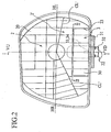
- the lower reflector 3 is divided from the lower part of the upper reflector 2, that is, the part below the horizontal axis HR-HL (or light axis Z-Z), so as to be substantially rectangular and symmetrical left-to-right about the vertical axis VU-VD when viewed from the front as shown in Fig. 2.
- the lower reflector 3 ise formed by cutting out of a part of the upper reflector 2 below the light axis Z-Z. As a result, a substantially rectangular aperture 23 is formed In the lower part of the upper reflector 2. The lower reflector 2 is thus disposed in the aperture 23 of the upper reflector 2.
- the upper reflector 2 is a fixed reflector fixed to a lamp housing (not shown in the drawing) via a bracket (not shown m the drawing).
- a single filament bulb 4 as a light source is detachably mounted at the substantially center part of the upper reflector 2.
- a reflective surface 20 forming a prescribed low-beam light-distribution pattern LP (used when passing opposing-direction vehicles) is provided on an inner surface of the upper reflector 2.
- This low-beam light-distribution pattern LP serves as the reference light-distribution pattern.
- the low-beam light-distribution pattern LP has a shape indicated by the solid line and part of the broken line in Fig. 4.
- the lower reflector 3 is rotatable with respect to the upper reflector 2.
- the two ends of a substantially L-shaped (viewed from the side thereof) mounting bracket 31 are fixed to the upper and lower edges of the aperture 23 of the upper reflector 2 by screws 22.
- the mounting bracket 31 is mounted so that it straddles across the upper edge and the lower edge of the aperture 23 of the upper reflector 2.
- a drive motor 32 is fixed at the substantially central part of the mounting bracket 31 as a drive means.
- the lower reflector 3 is fixed to a drive shaft of the drive motor 32. As a result, the lower reflector 3 can rotate with respect to the upper reflector 2.
- the lower reflector 3 can rotate to the left and right about a vertical axis VU-VD, which passes a vicinity of a focus F of either one or each of the reflective surface 20 of the upper reflector 2 and a reflective surface 30 of the lower reflector 3.
- the reflective surface 30 of the lower reflector 3 makes use of a conventionally unused amount of light to form a dispersed light-distribution pattern WP.
- the dispersed light-distributioin pattern WP has a shape indicated by the solid line protruding outward from the broken line of Fig. 4.
- a stepping motor is used as the drive motor 32.
- This stepping motor first causes a driven member (in this example, the lower reflector 3) to come into contact with a stopper in one direction, and is then stepped in the reverse direction by a prescribed number of steps to achieve a zero (reference) position setting, after which the motor is driven forward or reverse by a number of steps in accordance with information (in this example, the turning angle of the vehicle).
- a guide mechanism (33+34+37) is interposed between the lower reflector 3 and the mounting bracket 31.
- the guide mechanism is formed by a guide convex 33 projecting from the lower reflector 3, a plate spring 37 fixed to the guide convex 33, and a guide grooves 14 provided in the shape of an arc about the vertical axis VU-VD in the mounting bracket 31, so that the guide convex 33 and the plate spring 37 slidably pinch an edge of the guide groove 34.
- the above-noted upper reflector 2, lower reflector 3, single filament light source bulb 4, drive motor 32, and guide mechanism elements 33 and 34 are disposed within a lamp chamber (not shown in the drawing) delineated by a lamp housing and a front lens or front cover (not shown in the drawing), thereby forming a vehicular headlamp, which is installed at the left and right of the front of a vehicle.
- the upper reflector 2, along with the lower reflector 3, is mounted into the lamp housing via an intervening left-right light-axis adjustment mechanism (not shown in the drawing) and an intervening up-down light-axis adjustment mechanism (not shown in the drawing), so as to enable adjustment of the light axis left-and-right and up-and-down.
- the vehicular headlamp according to the first embodiment configured as described above is used as follows.
- the lower reflector With the vehicle traveling in a straight line, the lower reflector is at the neutral position, as shown in Fig. 1 to Fig. 3.
- the single filament light source bulb 4 When the single filament light source bulb 4 is lighted, light therefrom is reflected by the reflective surface 20 of the upper reflector 2 and the reflective surface 30 of the lower reflector 3, so that a prescribed low-beam light-distribution pattern LP as shown by the solid line and partial broken of Fig. 4 and the broken lines of Fig. 5 and Fig. 6 is obtained. Under this condition, the dispersed light-distribution pattern WP is positioned within the low-beam light-distribution pattern LP.
- the drive motor 32 is driven in accordance with information of the turning angle of the vehicle, so that the lower reflector 3 is rotated toward the right through a prescribed commanded angle about the vertical axis VU-VD.
- the dispersed light-distribution pattern WP is swung to the right from the position indicated by the broken line of the light-distribution pattern LP for low beam, to the position indicated by the solid line, along the curve.
- the lower drive motor 32 is driven in accordance with information of the turning angle of the vehicle, so that the lower reflector 3 is rotated through a prescribed commanded angle toward the left, about the vertical axis VU-VD.
- the result is that the dispersed light-distribution pattern WP is swung leftward of the low beam light pattern LP, along the curve.
- the dispersed light-distribution pattern WP is changed with respect to the low-beam light-distribution pattern LP of the fixed reference light-distribution pattern, with a resultant improvement in visibility of pedestrians and obstacles on a road at night.
- the lower reflector 3 is rotatably disposed in the aperture 23 of the upper reflector 2, the area surrounding the movable lower reflector 3 is surrounded by the fixed upper reflector 2, so that even if the lower reflector 3 rotates, there is no change in the outer shape of the upper reflector 2.
- the outer shape of the shining reflector does not change, the design of the light-emitting surface is not sacrificed.
- the location at which the lower reflector 3 is disposed is cut out, so as to form the aperture 23, so that the rigidity of the upper reflector 2 is not lost.
- the rigidity (for example, torsional rigidity) of the mounting bracket 31 is great.
- the lower reflector 3 is also supported at both ends thereof by the highly rigid mounting bracket 31, via the drive motor 32 and the guide mechanism elements 33 and 37, the precision of the light distribution is improved, and there is an improvement in immunity to vibration of the vehicle.
- the lower reflector 3 is rotatable to the left and right about the vertical axis VU-VD passing a vicinity of the focus F of the reflective surface(s) 20 and/or 30 of the upper and/or lower reflector(s) 2 and/or 3, even when the lower reflector 3 is rotated, the focus F is kept in position, facilitating the light-distribution control.
- Fig. 7 to Fig. 9 show a second embodiment of a vehicular headlamp provided in a vehicle according to the present invention, in elements corresponding to elements in Fig. 1 to Fig. 6 are assigned the same reference numerals.
- the second embodiment is different from the first embodiment simply in that it has, on an optically inner side (upside in Fig. 7) of a horizontal lower wall 35 of a lower reflector 3, a plurality of triangle-wavy raised reflective elements 36 for reflecting light from a single filament light-source bulb 4 to illuminate an overhead sign for the vehicle.
- the vehicular headlamp according to the second embodiment exhibits like effects to the first embodiment.
- the reflective elements 36 are provided on the inner side of the horizontal lower wall 35 of the lower reflector 3
- the reflected light serves as an OVL (overhead sign lighting) that, as in Fig. 8, illuminates a location higher than a low beam light-distribution pattern LP, with an overhead sign lighting light-distribution pattern OP, which is dispersed wider both leftward and rightward, providing an increased visibility of an overhead sign for the vehicle.
- OVL overhead sign lighting
- a dispersed light-distribution pattern WP is swung to the right from a position of the low beam light-distribution pattern LP indicated by solid line to a position indicated by broken line, along the curve, and concurrently, also the OVL light-distribution pattern is swung to the right from a position indicated by solid line to a position indicated by broken line, permitting an earlier eye-catch of an overhead sign 5 provided in course of the curve.
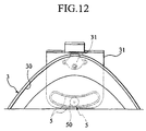
- Fig. 10 to Fig. 13(A), (B) and (C) show third embodiment of a vehicular headlamp provided in a vehicle according to the present invention, in elements corresponding to described elements are assigned the same reference numerals.
- the third embodiment is different from the first embodiment in that upper and lower reflectors 2 and 3 have a separation line therebetween straight extending in parallel to the reference plant containing the light axis Z-Z so that a reflective surface 30 of the lower reflector 3 is positioned below those lines CL' which provide a cut line CL of a low-beam reference light-distribution pattern LP formed by a reflective surface 20 of the upper reflector 2, and that a guide mechanism (50+51) is fowardly set off relative to a vertical axis VU-VD for the lower reflector 3 and/or the upper reflector 2 to rotate thereabout.
- the reflective surface 20 on an inside of the upper reflector 2 is configured to form the low-beam reference light-distribution pattern LP, which is shown in Fig. 13A.
- the reflective surface 30 on an inside of the lower reflector 3 is configured for utilization of concoupionaly unused light to form a dispersed light-distribution pattern WP shown in Fig. 13B, to be combined with the reference light-distribution pattern LP of Fig. 13A, thereby to provide a synthesized light-distribution patttern shown in Fig. 13C.
- the lower reflector 3 With the vehicle traveling in a straight line, the lower reflector 3 is at the neutral position, as shown in Fig. 10 to Fig. 12.
- the single filament light source bulb 4 When the single filament light source bulb 4 is lighted, light therefrom is reflected by the reflective surface 20 of the upper reflector 2 and the reflective surface 30 of the lower reflector 3, so that a prescribed low-beam light-distribution pattern LP as shown in Fig. 13A and Fig. 4, when a dispersed light-distribution pattern WP in Fig. 13B is positioned within the low-beam light-distribution pattern LP in Fig. 4, refer to Fig. 13C.
- a drive motor 32 is driven in accordance with information of the turning angle of the vehicle, so that the lower reflector 3 is rotated toward the right through a commanded angle about a vertical axis VU-VD.
- the dispersed light-distribution pattern WP is swung to the right from the position indicated by the broken line of the light-distribution pattern LP for low beam, to the position indicated by the solid line, along the curve.
- the lower drive motor 32 is driven in accordance with information of the turning angle of the vehicle, so that the lower reflector 3 is rotated through a commanded angle toward the left, about the vertical axis VU-VD.
- the result is that the dispersed light-distribution pattern WP is swung leftward of the low beam light pattern LP, along the curve.
- the guide mechanism (50+51) is disposed between a front part of the lowre reflector 3 and a lower end of a mounting bracket 31, at a location spaced apart from the rotation axis (vertical axis VU-VD) of the lower reflector 3.
- This guide mechanism is made up by a guide wheel 50 rotatably mounted via bearings to a downsdie of the front part of the lowre reflector 3, and a guide rail 51 integrally formed or provided, in a arc form with respect to the vertical axis VU-VD, on an upside of the lower end of the mounting bracket 31, and the guide wheel 50 is adapted to roll on the guide rail 51.
- the guide mechanism serves as a support mechasim such that an outer periphery of the guide wheel 50 and an inner surface of the guide rail 51 bear radial loads, and a downside of the lower reflector 3 and an upside of the guide rail 51 bear thrust loads.
- the guide mechanism furter serves as a stopper for a 0 setting of the stepping motor.
- the lower reflector 3 which has not particularly been used in the past, it is possible to maintain the amount of light from the basic low-beam light-distribution pattern LP while making sufficient use of light from the light source bulb 4.
- the basic low-beam light-distribution pattern LP was formed above the line CL' (see Fig. 2) that forms the cutting line CL (see Fig. 4) of the reflectors 2 and 3. For this reason, of the reflectors 2 and 3, the part below the cutting line CL' was not used, light striking this lower reflector not being actively used.
- the mounting bracket 31 fixed at two ends thereof may be a cantilever structure, and the lower reflector 3 held at two ends thereof to the mounting bracket 31 may be held in a cantilever manner.
- the light source composed of the single filament light-source bulb 4 may comprise a different light-source bulb, for example, a double-filament light-source lamp with no light-blocking plate within the glass envelope, or a discharge lamp (such as a high-intensity discharge lamp HID, a high-pressure metallic vapor discharge lamp such as a metal halide lamp).
- a discharge lamp such as a high-intensity discharge lamp HID, a high-pressure metallic vapor discharge lamp such as a metal halide lamp.
- the reference light-distribution pattern can be either the low-beam light-distribution pattern LP or the high-beam light-distribution pattern.
- the low beam light-distribution pattern LP, dispersed light-distribution pattern WP, and OVL light-distribution pattern OP may be controlled simply by the reflective surfaces 20 and 30, or by combination of them with a front lens, or by mere use of the front lens.
- the description is for the case in which the vehicular headlamp is applied as a headlamp for use in an area in which driving is done on the left side of the road, it will be understood that that the structure and the light-distribution patterns and the like would be reversed left-to-right for use in an area in which driving is done on the right side of the road.
Landscapes
- Engineering & Computer Science (AREA)
- General Engineering & Computer Science (AREA)
- Mechanical Engineering (AREA)
- Non-Portable Lighting Devices Or Systems Thereof (AREA)
- Lighting Device Outwards From Vehicle And Optical Signal (AREA)
Claims (7)
- Ein Fahrzeugscheinwerfer, umfassend:einen Reflektor mit einer ersten reflektierenden Oberfläche (20) und einer zweiten reflektierenden Oberfläche (30), die gegenüber der ersten reflektierenden Oberfläche (20) beweglich ist; und eine Lichtquellenglühlampe (4), die auf einer Lichtachse (Z - Z) der ersten reflektierenden Oberfläche (20) angeordnet ist, wobei der Reflektor in zwei Teile, einen oberen Reflektor (2), der eine horizontale Bezugsebene, die die Lichtachse (Z - Z) einschließt, schneidet, und einen unteren Reflektor (3), der unterhalb der horizontalen Bezugsebene positioniert ist, unterteilt ist, dadurch gekennzeichnet, dass die zweite reflektierende Oberfläche (30) in einem Schattenbereich (2') des Reflektors bereitgestellt wird, wobei ein Referenzlichtverteilungsmuster für Abblendlicht (LP) mit einer Schnittlinie (CL), die durch eine Trennlinie zwischen dem oberen Reflektor (2) und dem unteren Reflektor (3) gebildet wird, und durch das Licht von der Lichtquellenglühlampe (4), das von der ersten reflektierenden Oberfläche (20) und dem Schattenbereich (2') reflektiert wird, gebildet wird, und ein gestreutes Lichtverteilungsmuster für Abblendlicht (WP) relativ zu dem Referenzlichtverteilungsmuster (LP) durch das Licht von der Lichtquellenglühlampe (4), das von der zweiten reflektierenden Oberfläche (30) reflektiert wird, gebildet wird.
- Ein Fahrzeugscheinwerfer gemäß Anspruch 1, dadurch gekennzeichnet, dass der untere Reflektor (3) um eine vertikale Achse (VU - VD), die einem Brennpunkt (F) der ersten oder zweiten reflektierenden Oberfläche (20, 30) benachbart ist, drehbar ist.
- Ein Fahrzeugscheinwerfer gemäß Anspruch 1, dadurch gekennzeichnet, dass der untere Reflektor (3) relativ zu einer Halterung (31), die an dem oberen Reflektor (2) befestigt ist, drehbar ist.
- Ein Fahrzeugscheinwerfer gemäß Anspruch 1, dadurch gekennzeichnet, dass die zweite reflektierende Oberfläche (30) ein reflektierendes Element (36) für eine Ausleuchtung eines über Kopf befindlichen Schilds eines Fahrzeugs umfasst.
- Ein Fahrzeugscheinwerfer gemäß Anspruch 1, dadurch gekennzeichnet, dass der untere Reflektor (3) um eine vertikale Achse (VU - VD), die einem Brennpunkt (F) der ersten und zweiten reflektierenden Oberfläche (20, 30) benachbart ist, drehbar ist.
- Ein Fahrzeugscheinwerfer gemäß Anspruch 1, dadurch gekennzeichnet, dass der untere Reflektor (3) relativ zu einer Halterung (31), die an dem oberen Reflektor (2) befestigt ist, drehbar ist und durch die Halterung (31) führbar gestützt wird.
- Ein Fahrzeug, das mit einem Fahrzeugscheinwerfer gemäß einem der Ansprüche 1 bis 6 ausgestattet ist.
Applications Claiming Priority (4)
| Application Number | Priority Date | Filing Date | Title |
|---|---|---|---|
| JP34501199 | 1999-12-03 | ||
| JP34501199A JP2001158286A (ja) | 1999-12-03 | 1999-12-03 | 自動車用ヘッドランプ |
| JP34501599 | 1999-12-03 | ||
| JP34501599A JP2001158288A (ja) | 1999-12-03 | 1999-12-03 | 自動車用ヘッドランプ |
Publications (3)
| Publication Number | Publication Date |
|---|---|
| EP1106908A2 EP1106908A2 (de) | 2001-06-13 |
| EP1106908A3 EP1106908A3 (de) | 2004-02-18 |
| EP1106908B1 true EP1106908B1 (de) | 2006-03-01 |
Family
ID=26577937
Family Applications (1)
| Application Number | Title | Priority Date | Filing Date |
|---|---|---|---|
| EP00126309A Expired - Lifetime EP1106908B1 (de) | 1999-12-03 | 2000-12-01 | Fahrzeugscheiwerfer und Fahrzeug, welches mit diesem ausgestattet ist |
Country Status (3)
| Country | Link |
|---|---|
| US (1) | US6578995B2 (de) |
| EP (1) | EP1106908B1 (de) |
| DE (1) | DE60026221T2 (de) |
Families Citing this family (9)
| Publication number | Priority date | Publication date | Assignee | Title |
|---|---|---|---|---|
| JP4087201B2 (ja) * | 2002-09-20 | 2008-05-21 | 株式会社小糸製作所 | 車両用前照灯装置の光軸位置設定方法 |
| US7021804B2 (en) * | 2003-08-13 | 2006-04-04 | Guide Corporation | Lamp assembly with multi-stage reflector |
| US7018078B2 (en) * | 2003-08-29 | 2006-03-28 | Guide Corporation | Light assembly with bending light |
| DE102004003402A1 (de) * | 2004-01-23 | 2005-08-11 | Bayerische Motoren Werke Ag | Fahrzeugscheinwerfer |
| US7290907B2 (en) * | 2006-02-24 | 2007-11-06 | Honda Motor Co., Ltd | Vehicle headlamp with daytime running light |
| EP2559935B1 (de) | 2010-04-13 | 2020-07-01 | Koito Manufacturing Co., Ltd. | Optische einheit |
| FR3017189B1 (fr) * | 2014-02-04 | 2019-04-26 | Valeo Vision | Module d'eclairage et/ou de signalisation rotatif a source lumineuse fixe |
| KR101683993B1 (ko) * | 2014-11-04 | 2016-12-08 | 현대자동차주식회사 | 차량용 등화 장치 |
| CN113587002B (zh) * | 2021-09-30 | 2023-12-19 | 东莞福摩斯托电子有限公司 | 通过镜面反射镜结构实现聚光效果的led照明灯具 |
Family Cites Families (10)
| Publication number | Priority date | Publication date | Assignee | Title |
|---|---|---|---|---|
| JPH076564Y2 (ja) * | 1990-04-19 | 1995-02-15 | 株式会社小糸製作所 | 配光可変型自動車用前照灯 |
| JPH07108201B2 (ja) | 1991-01-09 | 1995-11-22 | 名古屋製酪株式会社 | ホイップクリーム組成物 |
| JPH0523216A (ja) | 1991-07-18 | 1993-02-02 | Sharp Corp | 充電式電動歯ブラシ |
| JPH05286392A (ja) * | 1992-04-07 | 1993-11-02 | Nissan Motor Co Ltd | 車両用前照灯 |
| JP3493611B2 (ja) | 1993-12-29 | 2004-02-03 | 本田技研工業株式会社 | 自動二輪車用の前照灯 |
| DE4418135B4 (de) * | 1994-05-25 | 2005-05-04 | Automotive Lighting Reutlingen Gmbh | Kraftfahrzeugscheinwerfer mit veränderbarer Lichtverteilung |
| FR2727497A1 (fr) * | 1994-11-30 | 1996-05-31 | Valeo Vision | Projecteur a elargissement de faisceau, notamment pour vehicule automobile |
| JP2955199B2 (ja) * | 1994-12-29 | 1999-10-04 | 本田技研工業株式会社 | 可変配光ヘッドランプ装置 |
| DE19624244B4 (de) * | 1996-06-18 | 2010-01-14 | Automotive Lighting Reutlingen Gmbh | Leuchte für Fahrzeuge |
| JP3526181B2 (ja) | 1997-09-12 | 2004-05-10 | 本田技研工業株式会社 | 車両用前照灯装置 |
-
2000
- 2000-12-01 DE DE60026221T patent/DE60026221T2/de not_active Expired - Fee Related
- 2000-12-01 EP EP00126309A patent/EP1106908B1/de not_active Expired - Lifetime
- 2000-12-04 US US09/727,551 patent/US6578995B2/en not_active Expired - Fee Related
Also Published As
| Publication number | Publication date |
|---|---|
| DE60026221T2 (de) | 2006-08-03 |
| DE60026221D1 (de) | 2006-04-27 |
| US6578995B2 (en) | 2003-06-17 |
| EP1106908A3 (de) | 2004-02-18 |
| EP1106908A2 (de) | 2001-06-13 |
| US20010002879A1 (en) | 2001-06-07 |
Similar Documents
| Publication | Publication Date | Title |
|---|---|---|
| JP4193713B2 (ja) | ヘッドランプ | |
| JP4523100B2 (ja) | 種々の特性を有する光束を発生するための車両用ヘッドライト装置 | |
| JP3488960B2 (ja) | 車両用前照灯 | |
| GB2352801A (en) | Vehicle headlamp | |
| US6565246B2 (en) | Vehicular headlamp and vehicle provided with same | |
| KR100438685B1 (ko) | 자동차의 헤드램프 | |
| EP1106908B1 (de) | Fahrzeugscheiwerfer und Fahrzeug, welches mit diesem ausgestattet ist | |
| JP3553471B2 (ja) | 車両用前照灯 | |
| EP2141732B1 (de) | Automobillampe und Reflektor für Abblend- und Kurvenlicht | |
| EP1538021B1 (de) | Fahrzeugleuchte | |
| KR100486336B1 (ko) | 자동차용 헤드램프 | |
| JP4743123B2 (ja) | 車両用前照灯 | |
| KR100486343B1 (ko) | 자동차용 헤드램프 | |
| KR100486339B1 (ko) | 자동차용 헤드램프 | |
| JP2008277130A (ja) | 車両用灯具 | |
| JP4702323B2 (ja) | 車両用前照灯 | |
| US7213954B2 (en) | Variable adaptive projector system for motor vehicles | |
| JP4442754B2 (ja) | ヘッドランプ | |
| KR100478300B1 (ko) | 자동차용 헤드램프 | |
| KR100486337B1 (ko) | 자동차용 헤드램프 | |
| JP4743124B2 (ja) | 車両用前照灯 | |
| JP4735392B2 (ja) | 車両用前照灯 | |
| JP2001351411A (ja) | 自動車用フォグランプ | |
| CN113531481A (zh) | 初级光学元件、远光照明装置、车灯及车辆 | |
| JP4605118B2 (ja) | 車両用前照灯 |
Legal Events
| Date | Code | Title | Description |
|---|---|---|---|
| PUAI | Public reference made under article 153(3) epc to a published international application that has entered the european phase |
Free format text: ORIGINAL CODE: 0009012 |
|
| 17P | Request for examination filed |
Effective date: 20001201 |
|
| AK | Designated contracting states |
Kind code of ref document: A2 Designated state(s): AT BE CH CY DE DK ES FI FR GB GR IE IT LI LU MC NL PT SE TR |
|
| AX | Request for extension of the european patent |
Free format text: AL;LT;LV;MK;RO;SI |
|
| PUAL | Search report despatched |
Free format text: ORIGINAL CODE: 0009013 |
|
| AK | Designated contracting states |
Kind code of ref document: A3 Designated state(s): AT BE CH CY DE DK ES FI FR GB GR IE IT LI LU MC NL PT SE TR |
|
| AX | Request for extension of the european patent |
Extension state: AL LT LV MK RO SI |
|
| RIC1 | Information provided on ipc code assigned before grant |
Ipc: 7F 21V 7/00 B Ipc: 7F 21V 14/04 B Ipc: 7B 60Q 1/12 A |
|
| 17Q | First examination report despatched |
Effective date: 20040819 |
|
| AKX | Designation fees paid |
Designated state(s): DE FR GB |
|
| GRAP | Despatch of communication of intention to grant a patent |
Free format text: ORIGINAL CODE: EPIDOSNIGR1 |
|
| GRAS | Grant fee paid |
Free format text: ORIGINAL CODE: EPIDOSNIGR3 |
|
| GRAA | (expected) grant |
Free format text: ORIGINAL CODE: 0009210 |
|
| AK | Designated contracting states |
Kind code of ref document: B1 Designated state(s): DE FR GB |
|
| REG | Reference to a national code |
Ref country code: GB Ref legal event code: FG4D |
|
| REF | Corresponds to: |
Ref document number: 60026221 Country of ref document: DE Date of ref document: 20060427 Kind code of ref document: P |
|
| ET | Fr: translation filed | ||
| PGFP | Annual fee paid to national office [announced via postgrant information from national office to epo] |
Ref country code: FR Payment date: 20061201 Year of fee payment: 7 |
|
| PGFP | Annual fee paid to national office [announced via postgrant information from national office to epo] |
Ref country code: GB Payment date: 20061204 Year of fee payment: 7 |
|
| PLBE | No opposition filed within time limit |
Free format text: ORIGINAL CODE: 0009261 |
|
| STAA | Information on the status of an ep patent application or granted ep patent |
Free format text: STATUS: NO OPPOSITION FILED WITHIN TIME LIMIT |
|
| PGFP | Annual fee paid to national office [announced via postgrant information from national office to epo] |
Ref country code: DE Payment date: 20070130 Year of fee payment: 7 |
|
| 26N | No opposition filed |
Effective date: 20061204 |
|
| GBPC | Gb: european patent ceased through non-payment of renewal fee |
Effective date: 20071201 |
|
| PG25 | Lapsed in a contracting state [announced via postgrant information from national office to epo] |
Ref country code: DE Free format text: LAPSE BECAUSE OF NON-PAYMENT OF DUE FEES Effective date: 20080701 |
|
| REG | Reference to a national code |
Ref country code: FR Ref legal event code: ST Effective date: 20081020 |
|
| PG25 | Lapsed in a contracting state [announced via postgrant information from national office to epo] |
Ref country code: GB Free format text: LAPSE BECAUSE OF NON-PAYMENT OF DUE FEES Effective date: 20071201 |
|
| PG25 | Lapsed in a contracting state [announced via postgrant information from national office to epo] |
Ref country code: FR Free format text: LAPSE BECAUSE OF NON-PAYMENT OF DUE FEES Effective date: 20071231 |