EP1103518B1 - Apparatus for reforming of fuel - Google Patents
Apparatus for reforming of fuel Download PDFInfo
- Publication number
- EP1103518B1 EP1103518B1 EP99928209A EP99928209A EP1103518B1 EP 1103518 B1 EP1103518 B1 EP 1103518B1 EP 99928209 A EP99928209 A EP 99928209A EP 99928209 A EP99928209 A EP 99928209A EP 1103518 B1 EP1103518 B1 EP 1103518B1
- Authority
- EP
- European Patent Office
- Prior art keywords
- unit
- reaction
- reformer
- fuel
- steam reforming
- Prior art date
- Legal status (The legal status is an assumption and is not a legal conclusion. Google has not performed a legal analysis and makes no representation as to the accuracy of the status listed.)
- Expired - Lifetime
Links
Images


Classifications
-
- H—ELECTRICITY
- H01—ELECTRIC ELEMENTS
- H01M—PROCESSES OR MEANS, e.g. BATTERIES, FOR THE DIRECT CONVERSION OF CHEMICAL ENERGY INTO ELECTRICAL ENERGY
- H01M8/00—Fuel cells; Manufacture thereof
- H01M8/06—Combination of fuel cells with means for production of reactants or for treatment of residues
- H01M8/0606—Combination of fuel cells with means for production of reactants or for treatment of residues with means for production of gaseous reactants
- H01M8/0612—Combination of fuel cells with means for production of reactants or for treatment of residues with means for production of gaseous reactants from carbon-containing material
- H01M8/0625—Combination of fuel cells with means for production of reactants or for treatment of residues with means for production of gaseous reactants from carbon-containing material in a modular combined reactor/fuel cell structure
- H01M8/0631—Reactor construction specially adapted for combination reactor/fuel cell
-
- B—PERFORMING OPERATIONS; TRANSPORTING
- B01—PHYSICAL OR CHEMICAL PROCESSES OR APPARATUS IN GENERAL
- B01B—BOILING; BOILING APPARATUS ; EVAPORATION; EVAPORATION APPARATUS
- B01B1/00—Boiling; Boiling apparatus for physical or chemical purposes ; Evaporation in general
- B01B1/005—Evaporation for physical or chemical purposes; Evaporation apparatus therefor, e.g. evaporation of liquids for gas phase reactions
-
- B—PERFORMING OPERATIONS; TRANSPORTING
- B01—PHYSICAL OR CHEMICAL PROCESSES OR APPARATUS IN GENERAL
- B01J—CHEMICAL OR PHYSICAL PROCESSES, e.g. CATALYSIS OR COLLOID CHEMISTRY; THEIR RELEVANT APPARATUS
- B01J19/00—Chemical, physical or physico-chemical processes in general; Their relevant apparatus
- B01J19/24—Stationary reactors without moving elements inside
- B01J19/2475—Membrane reactors
-
- B—PERFORMING OPERATIONS; TRANSPORTING
- B01—PHYSICAL OR CHEMICAL PROCESSES OR APPARATUS IN GENERAL
- B01J—CHEMICAL OR PHYSICAL PROCESSES, e.g. CATALYSIS OR COLLOID CHEMISTRY; THEIR RELEVANT APPARATUS
- B01J19/00—Chemical, physical or physico-chemical processes in general; Their relevant apparatus
- B01J19/24—Stationary reactors without moving elements inside
- B01J19/248—Reactors comprising multiple separated flow channels
- B01J19/2485—Monolithic reactors
-
- B—PERFORMING OPERATIONS; TRANSPORTING
- B01—PHYSICAL OR CHEMICAL PROCESSES OR APPARATUS IN GENERAL
- B01J—CHEMICAL OR PHYSICAL PROCESSES, e.g. CATALYSIS OR COLLOID CHEMISTRY; THEIR RELEVANT APPARATUS
- B01J8/00—Chemical or physical processes in general, conducted in the presence of fluids and solid particles; Apparatus for such processes
- B01J8/001—Controlling catalytic processes
-
- B—PERFORMING OPERATIONS; TRANSPORTING
- B01—PHYSICAL OR CHEMICAL PROCESSES OR APPARATUS IN GENERAL
- B01J—CHEMICAL OR PHYSICAL PROCESSES, e.g. CATALYSIS OR COLLOID CHEMISTRY; THEIR RELEVANT APPARATUS
- B01J8/00—Chemical or physical processes in general, conducted in the presence of fluids and solid particles; Apparatus for such processes
- B01J8/02—Chemical or physical processes in general, conducted in the presence of fluids and solid particles; Apparatus for such processes with stationary particles, e.g. in fixed beds
- B01J8/0207—Chemical or physical processes in general, conducted in the presence of fluids and solid particles; Apparatus for such processes with stationary particles, e.g. in fixed beds the fluid flow within the bed being predominantly horizontal
-
- B—PERFORMING OPERATIONS; TRANSPORTING
- B01—PHYSICAL OR CHEMICAL PROCESSES OR APPARATUS IN GENERAL
- B01J—CHEMICAL OR PHYSICAL PROCESSES, e.g. CATALYSIS OR COLLOID CHEMISTRY; THEIR RELEVANT APPARATUS
- B01J8/00—Chemical or physical processes in general, conducted in the presence of fluids and solid particles; Apparatus for such processes
- B01J8/02—Chemical or physical processes in general, conducted in the presence of fluids and solid particles; Apparatus for such processes with stationary particles, e.g. in fixed beds
- B01J8/0278—Feeding reactive fluids
-
- B—PERFORMING OPERATIONS; TRANSPORTING
- B01—PHYSICAL OR CHEMICAL PROCESSES OR APPARATUS IN GENERAL
- B01J—CHEMICAL OR PHYSICAL PROCESSES, e.g. CATALYSIS OR COLLOID CHEMISTRY; THEIR RELEVANT APPARATUS
- B01J8/00—Chemical or physical processes in general, conducted in the presence of fluids and solid particles; Apparatus for such processes
- B01J8/02—Chemical or physical processes in general, conducted in the presence of fluids and solid particles; Apparatus for such processes with stationary particles, e.g. in fixed beds
- B01J8/0285—Heating or cooling the reactor
-
- B—PERFORMING OPERATIONS; TRANSPORTING
- B01—PHYSICAL OR CHEMICAL PROCESSES OR APPARATUS IN GENERAL
- B01J—CHEMICAL OR PHYSICAL PROCESSES, e.g. CATALYSIS OR COLLOID CHEMISTRY; THEIR RELEVANT APPARATUS
- B01J8/00—Chemical or physical processes in general, conducted in the presence of fluids and solid particles; Apparatus for such processes
- B01J8/02—Chemical or physical processes in general, conducted in the presence of fluids and solid particles; Apparatus for such processes with stationary particles, e.g. in fixed beds
- B01J8/04—Chemical or physical processes in general, conducted in the presence of fluids and solid particles; Apparatus for such processes with stationary particles, e.g. in fixed beds the fluid passing successively through two or more beds
- B01J8/0403—Chemical or physical processes in general, conducted in the presence of fluids and solid particles; Apparatus for such processes with stationary particles, e.g. in fixed beds the fluid passing successively through two or more beds the fluid flow within the beds being predominantly horizontal
-
- B—PERFORMING OPERATIONS; TRANSPORTING
- B01—PHYSICAL OR CHEMICAL PROCESSES OR APPARATUS IN GENERAL
- B01J—CHEMICAL OR PHYSICAL PROCESSES, e.g. CATALYSIS OR COLLOID CHEMISTRY; THEIR RELEVANT APPARATUS
- B01J8/00—Chemical or physical processes in general, conducted in the presence of fluids and solid particles; Apparatus for such processes
- B01J8/02—Chemical or physical processes in general, conducted in the presence of fluids and solid particles; Apparatus for such processes with stationary particles, e.g. in fixed beds
- B01J8/04—Chemical or physical processes in general, conducted in the presence of fluids and solid particles; Apparatus for such processes with stationary particles, e.g. in fixed beds the fluid passing successively through two or more beds
- B01J8/0446—Chemical or physical processes in general, conducted in the presence of fluids and solid particles; Apparatus for such processes with stationary particles, e.g. in fixed beds the fluid passing successively through two or more beds the flow within the beds being predominantly vertical
-
- B—PERFORMING OPERATIONS; TRANSPORTING
- B01—PHYSICAL OR CHEMICAL PROCESSES OR APPARATUS IN GENERAL
- B01J—CHEMICAL OR PHYSICAL PROCESSES, e.g. CATALYSIS OR COLLOID CHEMISTRY; THEIR RELEVANT APPARATUS
- B01J8/00—Chemical or physical processes in general, conducted in the presence of fluids and solid particles; Apparatus for such processes
- B01J8/02—Chemical or physical processes in general, conducted in the presence of fluids and solid particles; Apparatus for such processes with stationary particles, e.g. in fixed beds
- B01J8/04—Chemical or physical processes in general, conducted in the presence of fluids and solid particles; Apparatus for such processes with stationary particles, e.g. in fixed beds the fluid passing successively through two or more beds
- B01J8/0492—Feeding reactive fluids
-
- B—PERFORMING OPERATIONS; TRANSPORTING
- B01—PHYSICAL OR CHEMICAL PROCESSES OR APPARATUS IN GENERAL
- B01J—CHEMICAL OR PHYSICAL PROCESSES, e.g. CATALYSIS OR COLLOID CHEMISTRY; THEIR RELEVANT APPARATUS
- B01J8/00—Chemical or physical processes in general, conducted in the presence of fluids and solid particles; Apparatus for such processes
- B01J8/02—Chemical or physical processes in general, conducted in the presence of fluids and solid particles; Apparatus for such processes with stationary particles, e.g. in fixed beds
- B01J8/04—Chemical or physical processes in general, conducted in the presence of fluids and solid particles; Apparatus for such processes with stationary particles, e.g. in fixed beds the fluid passing successively through two or more beds
- B01J8/0496—Heating or cooling the reactor
-
- B—PERFORMING OPERATIONS; TRANSPORTING
- B01—PHYSICAL OR CHEMICAL PROCESSES OR APPARATUS IN GENERAL
- B01J—CHEMICAL OR PHYSICAL PROCESSES, e.g. CATALYSIS OR COLLOID CHEMISTRY; THEIR RELEVANT APPARATUS
- B01J8/00—Chemical or physical processes in general, conducted in the presence of fluids and solid particles; Apparatus for such processes
- B01J8/02—Chemical or physical processes in general, conducted in the presence of fluids and solid particles; Apparatus for such processes with stationary particles, e.g. in fixed beds
- B01J8/06—Chemical or physical processes in general, conducted in the presence of fluids and solid particles; Apparatus for such processes with stationary particles, e.g. in fixed beds in tube reactors; the solid particles being arranged in tubes
- B01J8/067—Heating or cooling the reactor
-
- B—PERFORMING OPERATIONS; TRANSPORTING
- B01—PHYSICAL OR CHEMICAL PROCESSES OR APPARATUS IN GENERAL
- B01J—CHEMICAL OR PHYSICAL PROCESSES, e.g. CATALYSIS OR COLLOID CHEMISTRY; THEIR RELEVANT APPARATUS
- B01J8/00—Chemical or physical processes in general, conducted in the presence of fluids and solid particles; Apparatus for such processes
- B01J8/08—Chemical or physical processes in general, conducted in the presence of fluids and solid particles; Apparatus for such processes with moving particles
- B01J8/085—Feeding reactive fluids
-
- B—PERFORMING OPERATIONS; TRANSPORTING
- B01—PHYSICAL OR CHEMICAL PROCESSES OR APPARATUS IN GENERAL
- B01J—CHEMICAL OR PHYSICAL PROCESSES, e.g. CATALYSIS OR COLLOID CHEMISTRY; THEIR RELEVANT APPARATUS
- B01J8/00—Chemical or physical processes in general, conducted in the presence of fluids and solid particles; Apparatus for such processes
- B01J8/08—Chemical or physical processes in general, conducted in the presence of fluids and solid particles; Apparatus for such processes with moving particles
- B01J8/087—Heating or cooling the reactor
-
- B—PERFORMING OPERATIONS; TRANSPORTING
- B01—PHYSICAL OR CHEMICAL PROCESSES OR APPARATUS IN GENERAL
- B01J—CHEMICAL OR PHYSICAL PROCESSES, e.g. CATALYSIS OR COLLOID CHEMISTRY; THEIR RELEVANT APPARATUS
- B01J8/00—Chemical or physical processes in general, conducted in the presence of fluids and solid particles; Apparatus for such processes
- B01J8/08—Chemical or physical processes in general, conducted in the presence of fluids and solid particles; Apparatus for such processes with moving particles
- B01J8/10—Chemical or physical processes in general, conducted in the presence of fluids and solid particles; Apparatus for such processes with moving particles moved by stirrers or by rotary drums or rotary receptacles or endless belts
-
- C—CHEMISTRY; METALLURGY
- C01—INORGANIC CHEMISTRY
- C01B—NON-METALLIC ELEMENTS; COMPOUNDS THEREOF; METALLOIDS OR COMPOUNDS THEREOF NOT COVERED BY SUBCLASS C01C
- C01B3/00—Hydrogen; Gaseous mixtures containing hydrogen; Separation of hydrogen from mixtures containing it; Purification of hydrogen
- C01B3/02—Production of hydrogen or of gaseous mixtures containing a substantial proportion of hydrogen
- C01B3/32—Production of hydrogen or of gaseous mixtures containing a substantial proportion of hydrogen by reaction of gaseous or liquid organic compounds with gasifying agents, e.g. water, carbon dioxide, air
- C01B3/323—Catalytic reaction of gaseous or liquid organic compounds other than hydrocarbons with gasifying agents
-
- C—CHEMISTRY; METALLURGY
- C01—INORGANIC CHEMISTRY
- C01B—NON-METALLIC ELEMENTS; COMPOUNDS THEREOF; METALLOIDS OR COMPOUNDS THEREOF NOT COVERED BY SUBCLASS C01C
- C01B3/00—Hydrogen; Gaseous mixtures containing hydrogen; Separation of hydrogen from mixtures containing it; Purification of hydrogen
- C01B3/02—Production of hydrogen or of gaseous mixtures containing a substantial proportion of hydrogen
- C01B3/32—Production of hydrogen or of gaseous mixtures containing a substantial proportion of hydrogen by reaction of gaseous or liquid organic compounds with gasifying agents, e.g. water, carbon dioxide, air
- C01B3/34—Production of hydrogen or of gaseous mixtures containing a substantial proportion of hydrogen by reaction of gaseous or liquid organic compounds with gasifying agents, e.g. water, carbon dioxide, air by reaction of hydrocarbons with gasifying agents
- C01B3/38—Production of hydrogen or of gaseous mixtures containing a substantial proportion of hydrogen by reaction of gaseous or liquid organic compounds with gasifying agents, e.g. water, carbon dioxide, air by reaction of hydrocarbons with gasifying agents using catalysts
- C01B3/382—Multi-step processes
-
- C—CHEMISTRY; METALLURGY
- C01—INORGANIC CHEMISTRY
- C01B—NON-METALLIC ELEMENTS; COMPOUNDS THEREOF; METALLOIDS OR COMPOUNDS THEREOF NOT COVERED BY SUBCLASS C01C
- C01B3/00—Hydrogen; Gaseous mixtures containing hydrogen; Separation of hydrogen from mixtures containing it; Purification of hydrogen
- C01B3/02—Production of hydrogen or of gaseous mixtures containing a substantial proportion of hydrogen
- C01B3/32—Production of hydrogen or of gaseous mixtures containing a substantial proportion of hydrogen by reaction of gaseous or liquid organic compounds with gasifying agents, e.g. water, carbon dioxide, air
- C01B3/34—Production of hydrogen or of gaseous mixtures containing a substantial proportion of hydrogen by reaction of gaseous or liquid organic compounds with gasifying agents, e.g. water, carbon dioxide, air by reaction of hydrocarbons with gasifying agents
- C01B3/38—Production of hydrogen or of gaseous mixtures containing a substantial proportion of hydrogen by reaction of gaseous or liquid organic compounds with gasifying agents, e.g. water, carbon dioxide, air by reaction of hydrocarbons with gasifying agents using catalysts
- C01B3/386—Catalytic partial combustion
-
- H—ELECTRICITY
- H01—ELECTRIC ELEMENTS
- H01M—PROCESSES OR MEANS, e.g. BATTERIES, FOR THE DIRECT CONVERSION OF CHEMICAL ENERGY INTO ELECTRICAL ENERGY
- H01M8/00—Fuel cells; Manufacture thereof
- H01M8/04—Auxiliary arrangements, e.g. for control of pressure or for circulation of fluids
-
- H—ELECTRICITY
- H01—ELECTRIC ELEMENTS
- H01M—PROCESSES OR MEANS, e.g. BATTERIES, FOR THE DIRECT CONVERSION OF CHEMICAL ENERGY INTO ELECTRICAL ENERGY
- H01M8/00—Fuel cells; Manufacture thereof
- H01M8/06—Combination of fuel cells with means for production of reactants or for treatment of residues
- H01M8/0606—Combination of fuel cells with means for production of reactants or for treatment of residues with means for production of gaseous reactants
- H01M8/0612—Combination of fuel cells with means for production of reactants or for treatment of residues with means for production of gaseous reactants from carbon-containing material
-
- B—PERFORMING OPERATIONS; TRANSPORTING
- B01—PHYSICAL OR CHEMICAL PROCESSES OR APPARATUS IN GENERAL
- B01J—CHEMICAL OR PHYSICAL PROCESSES, e.g. CATALYSIS OR COLLOID CHEMISTRY; THEIR RELEVANT APPARATUS
- B01J2208/00—Processes carried out in the presence of solid particles; Reactors therefor
- B01J2208/00008—Controlling the process
- B01J2208/00017—Controlling the temperature
- B01J2208/00026—Controlling or regulating the heat exchange system
- B01J2208/00035—Controlling or regulating the heat exchange system involving measured parameters
- B01J2208/00044—Temperature measurement
- B01J2208/00061—Temperature measurement of the reactants
-
- B—PERFORMING OPERATIONS; TRANSPORTING
- B01—PHYSICAL OR CHEMICAL PROCESSES OR APPARATUS IN GENERAL
- B01J—CHEMICAL OR PHYSICAL PROCESSES, e.g. CATALYSIS OR COLLOID CHEMISTRY; THEIR RELEVANT APPARATUS
- B01J2208/00—Processes carried out in the presence of solid particles; Reactors therefor
- B01J2208/00008—Controlling the process
- B01J2208/00017—Controlling the temperature
- B01J2208/00026—Controlling or regulating the heat exchange system
- B01J2208/00035—Controlling or regulating the heat exchange system involving measured parameters
- B01J2208/00088—Flow rate measurement
-
- B—PERFORMING OPERATIONS; TRANSPORTING
- B01—PHYSICAL OR CHEMICAL PROCESSES OR APPARATUS IN GENERAL
- B01J—CHEMICAL OR PHYSICAL PROCESSES, e.g. CATALYSIS OR COLLOID CHEMISTRY; THEIR RELEVANT APPARATUS
- B01J2208/00—Processes carried out in the presence of solid particles; Reactors therefor
- B01J2208/00008—Controlling the process
- B01J2208/00017—Controlling the temperature
- B01J2208/00106—Controlling the temperature by indirect heat exchange
- B01J2208/00309—Controlling the temperature by indirect heat exchange with two or more reactions in heat exchange with each other, such as an endothermic reaction in heat exchange with an exothermic reaction
-
- B—PERFORMING OPERATIONS; TRANSPORTING
- B01—PHYSICAL OR CHEMICAL PROCESSES OR APPARATUS IN GENERAL
- B01J—CHEMICAL OR PHYSICAL PROCESSES, e.g. CATALYSIS OR COLLOID CHEMISTRY; THEIR RELEVANT APPARATUS
- B01J2208/00—Processes carried out in the presence of solid particles; Reactors therefor
- B01J2208/00008—Controlling the process
- B01J2208/00017—Controlling the temperature
- B01J2208/00327—Controlling the temperature by direct heat exchange
- B01J2208/00336—Controlling the temperature by direct heat exchange adding a temperature modifying medium to the reactants
- B01J2208/00353—Non-cryogenic fluids
- B01J2208/00362—Liquid
-
- B—PERFORMING OPERATIONS; TRANSPORTING
- B01—PHYSICAL OR CHEMICAL PROCESSES OR APPARATUS IN GENERAL
- B01J—CHEMICAL OR PHYSICAL PROCESSES, e.g. CATALYSIS OR COLLOID CHEMISTRY; THEIR RELEVANT APPARATUS
- B01J2208/00—Processes carried out in the presence of solid particles; Reactors therefor
- B01J2208/00008—Controlling the process
- B01J2208/00548—Flow
-
- B—PERFORMING OPERATIONS; TRANSPORTING
- B01—PHYSICAL OR CHEMICAL PROCESSES OR APPARATUS IN GENERAL
- B01J—CHEMICAL OR PHYSICAL PROCESSES, e.g. CATALYSIS OR COLLOID CHEMISTRY; THEIR RELEVANT APPARATUS
- B01J2208/00—Processes carried out in the presence of solid particles; Reactors therefor
- B01J2208/02—Processes carried out in the presence of solid particles; Reactors therefor with stationary particles
- B01J2208/021—Processes carried out in the presence of solid particles; Reactors therefor with stationary particles comprising a plurality of beds with flow of reactants in parallel
-
- B—PERFORMING OPERATIONS; TRANSPORTING
- B01—PHYSICAL OR CHEMICAL PROCESSES OR APPARATUS IN GENERAL
- B01J—CHEMICAL OR PHYSICAL PROCESSES, e.g. CATALYSIS OR COLLOID CHEMISTRY; THEIR RELEVANT APPARATUS
- B01J2219/00—Chemical, physical or physico-chemical processes in general; Their relevant apparatus
- B01J2219/00049—Controlling or regulating processes
- B01J2219/00051—Controlling the temperature
- B01J2219/00054—Controlling or regulating the heat exchange system
- B01J2219/00056—Controlling or regulating the heat exchange system involving measured parameters
- B01J2219/00058—Temperature measurement
- B01J2219/00063—Temperature measurement of the reactants
-
- B—PERFORMING OPERATIONS; TRANSPORTING
- B01—PHYSICAL OR CHEMICAL PROCESSES OR APPARATUS IN GENERAL
- B01J—CHEMICAL OR PHYSICAL PROCESSES, e.g. CATALYSIS OR COLLOID CHEMISTRY; THEIR RELEVANT APPARATUS
- B01J2219/00—Chemical, physical or physico-chemical processes in general; Their relevant apparatus
- B01J2219/00049—Controlling or regulating processes
- B01J2219/00051—Controlling the temperature
- B01J2219/00054—Controlling or regulating the heat exchange system
- B01J2219/00056—Controlling or regulating the heat exchange system involving measured parameters
- B01J2219/00069—Flow rate measurement
-
- B—PERFORMING OPERATIONS; TRANSPORTING
- B01—PHYSICAL OR CHEMICAL PROCESSES OR APPARATUS IN GENERAL
- B01J—CHEMICAL OR PHYSICAL PROCESSES, e.g. CATALYSIS OR COLLOID CHEMISTRY; THEIR RELEVANT APPARATUS
- B01J2219/00—Chemical, physical or physico-chemical processes in general; Their relevant apparatus
- B01J2219/00049—Controlling or regulating processes
- B01J2219/00051—Controlling the temperature
- B01J2219/00074—Controlling the temperature by indirect heating or cooling employing heat exchange fluids
- B01J2219/00117—Controlling the temperature by indirect heating or cooling employing heat exchange fluids with two or more reactions in heat exchange with each other, such as an endothermic reaction in heat exchange with an exothermic reaction
-
- B—PERFORMING OPERATIONS; TRANSPORTING
- B01—PHYSICAL OR CHEMICAL PROCESSES OR APPARATUS IN GENERAL
- B01J—CHEMICAL OR PHYSICAL PROCESSES, e.g. CATALYSIS OR COLLOID CHEMISTRY; THEIR RELEVANT APPARATUS
- B01J2219/00—Chemical, physical or physico-chemical processes in general; Their relevant apparatus
- B01J2219/00049—Controlling or regulating processes
- B01J2219/00164—Controlling or regulating processes controlling the flow
-
- B—PERFORMING OPERATIONS; TRANSPORTING
- B01—PHYSICAL OR CHEMICAL PROCESSES OR APPARATUS IN GENERAL
- B01J—CHEMICAL OR PHYSICAL PROCESSES, e.g. CATALYSIS OR COLLOID CHEMISTRY; THEIR RELEVANT APPARATUS
- B01J2219/00—Chemical, physical or physico-chemical processes in general; Their relevant apparatus
- B01J2219/00049—Controlling or regulating processes
- B01J2219/00191—Control algorithm
- B01J2219/00193—Sensing a parameter
- B01J2219/00195—Sensing a parameter of the reaction system
- B01J2219/002—Sensing a parameter of the reaction system inside the reactor
-
- B—PERFORMING OPERATIONS; TRANSPORTING
- B01—PHYSICAL OR CHEMICAL PROCESSES OR APPARATUS IN GENERAL
- B01J—CHEMICAL OR PHYSICAL PROCESSES, e.g. CATALYSIS OR COLLOID CHEMISTRY; THEIR RELEVANT APPARATUS
- B01J2219/00—Chemical, physical or physico-chemical processes in general; Their relevant apparatus
- B01J2219/00049—Controlling or regulating processes
- B01J2219/00191—Control algorithm
- B01J2219/00211—Control algorithm comparing a sensed parameter with a pre-set value
- B01J2219/00213—Fixed parameter value
-
- B—PERFORMING OPERATIONS; TRANSPORTING
- B01—PHYSICAL OR CHEMICAL PROCESSES OR APPARATUS IN GENERAL
- B01J—CHEMICAL OR PHYSICAL PROCESSES, e.g. CATALYSIS OR COLLOID CHEMISTRY; THEIR RELEVANT APPARATUS
- B01J2219/00—Chemical, physical or physico-chemical processes in general; Their relevant apparatus
- B01J2219/00049—Controlling or regulating processes
- B01J2219/00191—Control algorithm
- B01J2219/00211—Control algorithm comparing a sensed parameter with a pre-set value
- B01J2219/0022—Control algorithm comparing a sensed parameter with a pre-set value calculating difference
-
- B—PERFORMING OPERATIONS; TRANSPORTING
- B01—PHYSICAL OR CHEMICAL PROCESSES OR APPARATUS IN GENERAL
- B01J—CHEMICAL OR PHYSICAL PROCESSES, e.g. CATALYSIS OR COLLOID CHEMISTRY; THEIR RELEVANT APPARATUS
- B01J2219/00—Chemical, physical or physico-chemical processes in general; Their relevant apparatus
- B01J2219/00049—Controlling or regulating processes
- B01J2219/00191—Control algorithm
- B01J2219/00222—Control algorithm taking actions
- B01J2219/00227—Control algorithm taking actions modifying the operating conditions
- B01J2219/00229—Control algorithm taking actions modifying the operating conditions of the reaction system
- B01J2219/00231—Control algorithm taking actions modifying the operating conditions of the reaction system at the reactor inlet
-
- B—PERFORMING OPERATIONS; TRANSPORTING
- B01—PHYSICAL OR CHEMICAL PROCESSES OR APPARATUS IN GENERAL
- B01J—CHEMICAL OR PHYSICAL PROCESSES, e.g. CATALYSIS OR COLLOID CHEMISTRY; THEIR RELEVANT APPARATUS
- B01J2219/00—Chemical, physical or physico-chemical processes in general; Their relevant apparatus
- B01J2219/18—Details relating to the spatial orientation of the reactor
- B01J2219/182—Details relating to the spatial orientation of the reactor horizontal
-
- C—CHEMISTRY; METALLURGY
- C01—INORGANIC CHEMISTRY
- C01B—NON-METALLIC ELEMENTS; COMPOUNDS THEREOF; METALLOIDS OR COMPOUNDS THEREOF NOT COVERED BY SUBCLASS C01C
- C01B2203/00—Integrated processes for the production of hydrogen or synthesis gas
- C01B2203/02—Processes for making hydrogen or synthesis gas
- C01B2203/0205—Processes for making hydrogen or synthesis gas containing a reforming step
- C01B2203/0227—Processes for making hydrogen or synthesis gas containing a reforming step containing a catalytic reforming step
- C01B2203/0233—Processes for making hydrogen or synthesis gas containing a reforming step containing a catalytic reforming step the reforming step being a steam reforming step
-
- C—CHEMISTRY; METALLURGY
- C01—INORGANIC CHEMISTRY
- C01B—NON-METALLIC ELEMENTS; COMPOUNDS THEREOF; METALLOIDS OR COMPOUNDS THEREOF NOT COVERED BY SUBCLASS C01C
- C01B2203/00—Integrated processes for the production of hydrogen or synthesis gas
- C01B2203/02—Processes for making hydrogen or synthesis gas
- C01B2203/0205—Processes for making hydrogen or synthesis gas containing a reforming step
- C01B2203/0227—Processes for making hydrogen or synthesis gas containing a reforming step containing a catalytic reforming step
- C01B2203/0244—Processes for making hydrogen or synthesis gas containing a reforming step containing a catalytic reforming step the reforming step being an autothermal reforming step, e.g. secondary reforming processes
-
- C—CHEMISTRY; METALLURGY
- C01—INORGANIC CHEMISTRY
- C01B—NON-METALLIC ELEMENTS; COMPOUNDS THEREOF; METALLOIDS OR COMPOUNDS THEREOF NOT COVERED BY SUBCLASS C01C
- C01B2203/00—Integrated processes for the production of hydrogen or synthesis gas
- C01B2203/04—Integrated processes for the production of hydrogen or synthesis gas containing a purification step for the hydrogen or the synthesis gas
- C01B2203/0435—Catalytic purification
- C01B2203/044—Selective oxidation of carbon monoxide
-
- C—CHEMISTRY; METALLURGY
- C01—INORGANIC CHEMISTRY
- C01B—NON-METALLIC ELEMENTS; COMPOUNDS THEREOF; METALLOIDS OR COMPOUNDS THEREOF NOT COVERED BY SUBCLASS C01C
- C01B2203/00—Integrated processes for the production of hydrogen or synthesis gas
- C01B2203/04—Integrated processes for the production of hydrogen or synthesis gas containing a purification step for the hydrogen or the synthesis gas
- C01B2203/0465—Composition of the impurity
- C01B2203/047—Composition of the impurity the impurity being carbon monoxide
-
- C—CHEMISTRY; METALLURGY
- C01—INORGANIC CHEMISTRY
- C01B—NON-METALLIC ELEMENTS; COMPOUNDS THEREOF; METALLOIDS OR COMPOUNDS THEREOF NOT COVERED BY SUBCLASS C01C
- C01B2203/00—Integrated processes for the production of hydrogen or synthesis gas
- C01B2203/06—Integration with other chemical processes
- C01B2203/066—Integration with other chemical processes with fuel cells
-
- C—CHEMISTRY; METALLURGY
- C01—INORGANIC CHEMISTRY
- C01B—NON-METALLIC ELEMENTS; COMPOUNDS THEREOF; METALLOIDS OR COMPOUNDS THEREOF NOT COVERED BY SUBCLASS C01C
- C01B2203/00—Integrated processes for the production of hydrogen or synthesis gas
- C01B2203/08—Methods of heating or cooling
- C01B2203/0805—Methods of heating the process for making hydrogen or synthesis gas
- C01B2203/0811—Methods of heating the process for making hydrogen or synthesis gas by combustion of fuel
- C01B2203/0822—Methods of heating the process for making hydrogen or synthesis gas by combustion of fuel the fuel containing hydrogen
-
- C—CHEMISTRY; METALLURGY
- C01—INORGANIC CHEMISTRY
- C01B—NON-METALLIC ELEMENTS; COMPOUNDS THEREOF; METALLOIDS OR COMPOUNDS THEREOF NOT COVERED BY SUBCLASS C01C
- C01B2203/00—Integrated processes for the production of hydrogen or synthesis gas
- C01B2203/08—Methods of heating or cooling
- C01B2203/0805—Methods of heating the process for making hydrogen or synthesis gas
- C01B2203/0811—Methods of heating the process for making hydrogen or synthesis gas by combustion of fuel
- C01B2203/0827—Methods of heating the process for making hydrogen or synthesis gas by combustion of fuel at least part of the fuel being a recycle stream
-
- C—CHEMISTRY; METALLURGY
- C01—INORGANIC CHEMISTRY
- C01B—NON-METALLIC ELEMENTS; COMPOUNDS THEREOF; METALLOIDS OR COMPOUNDS THEREOF NOT COVERED BY SUBCLASS C01C
- C01B2203/00—Integrated processes for the production of hydrogen or synthesis gas
- C01B2203/08—Methods of heating or cooling
- C01B2203/0805—Methods of heating the process for making hydrogen or synthesis gas
- C01B2203/0833—Heating by indirect heat exchange with hot fluids, other than combustion gases, product gases or non-combustive exothermic reaction product gases
-
- C—CHEMISTRY; METALLURGY
- C01—INORGANIC CHEMISTRY
- C01B—NON-METALLIC ELEMENTS; COMPOUNDS THEREOF; METALLOIDS OR COMPOUNDS THEREOF NOT COVERED BY SUBCLASS C01C
- C01B2203/00—Integrated processes for the production of hydrogen or synthesis gas
- C01B2203/08—Methods of heating or cooling
- C01B2203/0805—Methods of heating the process for making hydrogen or synthesis gas
- C01B2203/0838—Methods of heating the process for making hydrogen or synthesis gas by heat exchange with exothermic reactions, other than by combustion of fuel
- C01B2203/0844—Methods of heating the process for making hydrogen or synthesis gas by heat exchange with exothermic reactions, other than by combustion of fuel the non-combustive exothermic reaction being another reforming reaction as defined in groups C01B2203/02 - C01B2203/0294
-
- C—CHEMISTRY; METALLURGY
- C01—INORGANIC CHEMISTRY
- C01B—NON-METALLIC ELEMENTS; COMPOUNDS THEREOF; METALLOIDS OR COMPOUNDS THEREOF NOT COVERED BY SUBCLASS C01C
- C01B2203/00—Integrated processes for the production of hydrogen or synthesis gas
- C01B2203/08—Methods of heating or cooling
- C01B2203/0805—Methods of heating the process for making hydrogen or synthesis gas
- C01B2203/0866—Methods of heating the process for making hydrogen or synthesis gas by combination of different heating methods
-
- C—CHEMISTRY; METALLURGY
- C01—INORGANIC CHEMISTRY
- C01B—NON-METALLIC ELEMENTS; COMPOUNDS THEREOF; METALLOIDS OR COMPOUNDS THEREOF NOT COVERED BY SUBCLASS C01C
- C01B2203/00—Integrated processes for the production of hydrogen or synthesis gas
- C01B2203/08—Methods of heating or cooling
- C01B2203/0872—Methods of cooling
- C01B2203/0877—Methods of cooling by direct injection of fluid
-
- C—CHEMISTRY; METALLURGY
- C01—INORGANIC CHEMISTRY
- C01B—NON-METALLIC ELEMENTS; COMPOUNDS THEREOF; METALLOIDS OR COMPOUNDS THEREOF NOT COVERED BY SUBCLASS C01C
- C01B2203/00—Integrated processes for the production of hydrogen or synthesis gas
- C01B2203/10—Catalysts for performing the hydrogen forming reactions
- C01B2203/1005—Arrangement or shape of catalyst
- C01B2203/1011—Packed bed of catalytic structures, e.g. particles, packing elements
- C01B2203/1017—Packed bed of catalytic structures, e.g. particles, packing elements characterised by the form of the structure
-
- C—CHEMISTRY; METALLURGY
- C01—INORGANIC CHEMISTRY
- C01B—NON-METALLIC ELEMENTS; COMPOUNDS THEREOF; METALLOIDS OR COMPOUNDS THEREOF NOT COVERED BY SUBCLASS C01C
- C01B2203/00—Integrated processes for the production of hydrogen or synthesis gas
- C01B2203/10—Catalysts for performing the hydrogen forming reactions
- C01B2203/1005—Arrangement or shape of catalyst
- C01B2203/1023—Catalysts in the form of a monolith or honeycomb
-
- C—CHEMISTRY; METALLURGY
- C01—INORGANIC CHEMISTRY
- C01B—NON-METALLIC ELEMENTS; COMPOUNDS THEREOF; METALLOIDS OR COMPOUNDS THEREOF NOT COVERED BY SUBCLASS C01C
- C01B2203/00—Integrated processes for the production of hydrogen or synthesis gas
- C01B2203/10—Catalysts for performing the hydrogen forming reactions
- C01B2203/1005—Arrangement or shape of catalyst
- C01B2203/1035—Catalyst coated on equipment surfaces, e.g. reactor walls
-
- C—CHEMISTRY; METALLURGY
- C01—INORGANIC CHEMISTRY
- C01B—NON-METALLIC ELEMENTS; COMPOUNDS THEREOF; METALLOIDS OR COMPOUNDS THEREOF NOT COVERED BY SUBCLASS C01C
- C01B2203/00—Integrated processes for the production of hydrogen or synthesis gas
- C01B2203/10—Catalysts for performing the hydrogen forming reactions
- C01B2203/1041—Composition of the catalyst
- C01B2203/1047—Group VIII metal catalysts
- C01B2203/1064—Platinum group metal catalysts
-
- C—CHEMISTRY; METALLURGY
- C01—INORGANIC CHEMISTRY
- C01B—NON-METALLIC ELEMENTS; COMPOUNDS THEREOF; METALLOIDS OR COMPOUNDS THEREOF NOT COVERED BY SUBCLASS C01C
- C01B2203/00—Integrated processes for the production of hydrogen or synthesis gas
- C01B2203/10—Catalysts for performing the hydrogen forming reactions
- C01B2203/1041—Composition of the catalyst
- C01B2203/1076—Copper or zinc-based catalysts
-
- C—CHEMISTRY; METALLURGY
- C01—INORGANIC CHEMISTRY
- C01B—NON-METALLIC ELEMENTS; COMPOUNDS THEREOF; METALLOIDS OR COMPOUNDS THEREOF NOT COVERED BY SUBCLASS C01C
- C01B2203/00—Integrated processes for the production of hydrogen or synthesis gas
- C01B2203/10—Catalysts for performing the hydrogen forming reactions
- C01B2203/1041—Composition of the catalyst
- C01B2203/1082—Composition of support materials
-
- C—CHEMISTRY; METALLURGY
- C01—INORGANIC CHEMISTRY
- C01B—NON-METALLIC ELEMENTS; COMPOUNDS THEREOF; METALLOIDS OR COMPOUNDS THEREOF NOT COVERED BY SUBCLASS C01C
- C01B2203/00—Integrated processes for the production of hydrogen or synthesis gas
- C01B2203/12—Feeding the process for making hydrogen or synthesis gas
- C01B2203/1205—Composition of the feed
- C01B2203/1211—Organic compounds or organic mixtures used in the process for making hydrogen or synthesis gas
- C01B2203/1217—Alcohols
- C01B2203/1223—Methanol
-
- C—CHEMISTRY; METALLURGY
- C01—INORGANIC CHEMISTRY
- C01B—NON-METALLIC ELEMENTS; COMPOUNDS THEREOF; METALLOIDS OR COMPOUNDS THEREOF NOT COVERED BY SUBCLASS C01C
- C01B2203/00—Integrated processes for the production of hydrogen or synthesis gas
- C01B2203/12—Feeding the process for making hydrogen or synthesis gas
- C01B2203/1205—Composition of the feed
- C01B2203/1211—Organic compounds or organic mixtures used in the process for making hydrogen or synthesis gas
- C01B2203/1235—Hydrocarbons
-
- C—CHEMISTRY; METALLURGY
- C01—INORGANIC CHEMISTRY
- C01B—NON-METALLIC ELEMENTS; COMPOUNDS THEREOF; METALLOIDS OR COMPOUNDS THEREOF NOT COVERED BY SUBCLASS C01C
- C01B2203/00—Integrated processes for the production of hydrogen or synthesis gas
- C01B2203/12—Feeding the process for making hydrogen or synthesis gas
- C01B2203/1288—Evaporation of one or more of the different feed components
-
- C—CHEMISTRY; METALLURGY
- C01—INORGANIC CHEMISTRY
- C01B—NON-METALLIC ELEMENTS; COMPOUNDS THEREOF; METALLOIDS OR COMPOUNDS THEREOF NOT COVERED BY SUBCLASS C01C
- C01B2203/00—Integrated processes for the production of hydrogen or synthesis gas
- C01B2203/14—Details of the flowsheet
- C01B2203/141—At least two reforming, decomposition or partial oxidation steps in parallel
-
- C—CHEMISTRY; METALLURGY
- C01—INORGANIC CHEMISTRY
- C01B—NON-METALLIC ELEMENTS; COMPOUNDS THEREOF; METALLOIDS OR COMPOUNDS THEREOF NOT COVERED BY SUBCLASS C01C
- C01B2203/00—Integrated processes for the production of hydrogen or synthesis gas
- C01B2203/14—Details of the flowsheet
- C01B2203/142—At least two reforming, decomposition or partial oxidation steps in series
- C01B2203/143—Three or more reforming, decomposition or partial oxidation steps in series
-
- C—CHEMISTRY; METALLURGY
- C01—INORGANIC CHEMISTRY
- C01B—NON-METALLIC ELEMENTS; COMPOUNDS THEREOF; METALLOIDS OR COMPOUNDS THEREOF NOT COVERED BY SUBCLASS C01C
- C01B2203/00—Integrated processes for the production of hydrogen or synthesis gas
- C01B2203/16—Controlling the process
- C01B2203/1604—Starting up the process
-
- C—CHEMISTRY; METALLURGY
- C01—INORGANIC CHEMISTRY
- C01B—NON-METALLIC ELEMENTS; COMPOUNDS THEREOF; METALLOIDS OR COMPOUNDS THEREOF NOT COVERED BY SUBCLASS C01C
- C01B2203/00—Integrated processes for the production of hydrogen or synthesis gas
- C01B2203/16—Controlling the process
- C01B2203/1614—Controlling the temperature
- C01B2203/1619—Measuring the temperature
-
- C—CHEMISTRY; METALLURGY
- C01—INORGANIC CHEMISTRY
- C01B—NON-METALLIC ELEMENTS; COMPOUNDS THEREOF; METALLOIDS OR COMPOUNDS THEREOF NOT COVERED BY SUBCLASS C01C
- C01B2203/00—Integrated processes for the production of hydrogen or synthesis gas
- C01B2203/16—Controlling the process
- C01B2203/1642—Controlling the product
- C01B2203/1647—Controlling the amount of the product
- C01B2203/1652—Measuring the amount of product
- C01B2203/1661—Measuring the amount of product the product being carbon monoxide
-
- C—CHEMISTRY; METALLURGY
- C01—INORGANIC CHEMISTRY
- C01B—NON-METALLIC ELEMENTS; COMPOUNDS THEREOF; METALLOIDS OR COMPOUNDS THEREOF NOT COVERED BY SUBCLASS C01C
- C01B2203/00—Integrated processes for the production of hydrogen or synthesis gas
- C01B2203/16—Controlling the process
- C01B2203/169—Controlling the feed
-
- C—CHEMISTRY; METALLURGY
- C01—INORGANIC CHEMISTRY
- C01B—NON-METALLIC ELEMENTS; COMPOUNDS THEREOF; METALLOIDS OR COMPOUNDS THEREOF NOT COVERED BY SUBCLASS C01C
- C01B2203/00—Integrated processes for the production of hydrogen or synthesis gas
- C01B2203/16—Controlling the process
- C01B2203/1695—Adjusting the feed of the combustion
-
- C—CHEMISTRY; METALLURGY
- C01—INORGANIC CHEMISTRY
- C01B—NON-METALLIC ELEMENTS; COMPOUNDS THEREOF; METALLOIDS OR COMPOUNDS THEREOF NOT COVERED BY SUBCLASS C01C
- C01B2203/00—Integrated processes for the production of hydrogen or synthesis gas
- C01B2203/80—Aspect of integrated processes for the production of hydrogen or synthesis gas not covered by groups C01B2203/02 - C01B2203/1695
- C01B2203/82—Several process steps of C01B2203/02 - C01B2203/08 integrated into a single apparatus
-
- H—ELECTRICITY
- H01—ELECTRIC ELEMENTS
- H01M—PROCESSES OR MEANS, e.g. BATTERIES, FOR THE DIRECT CONVERSION OF CHEMICAL ENERGY INTO ELECTRICAL ENERGY
- H01M2300/00—Electrolytes
- H01M2300/0017—Non-aqueous electrolytes
- H01M2300/0065—Solid electrolytes
- H01M2300/0082—Organic polymers
-
- Y—GENERAL TAGGING OF NEW TECHNOLOGICAL DEVELOPMENTS; GENERAL TAGGING OF CROSS-SECTIONAL TECHNOLOGIES SPANNING OVER SEVERAL SECTIONS OF THE IPC; TECHNICAL SUBJECTS COVERED BY FORMER USPC CROSS-REFERENCE ART COLLECTIONS [XRACs] AND DIGESTS
- Y02—TECHNOLOGIES OR APPLICATIONS FOR MITIGATION OR ADAPTATION AGAINST CLIMATE CHANGE
- Y02E—REDUCTION OF GREENHOUSE GAS [GHG] EMISSIONS, RELATED TO ENERGY GENERATION, TRANSMISSION OR DISTRIBUTION
- Y02E60/00—Enabling technologies; Technologies with a potential or indirect contribution to GHG emissions mitigation
- Y02E60/30—Hydrogen technology
- Y02E60/50—Fuel cells
-
- Y—GENERAL TAGGING OF NEW TECHNOLOGICAL DEVELOPMENTS; GENERAL TAGGING OF CROSS-SECTIONAL TECHNOLOGIES SPANNING OVER SEVERAL SECTIONS OF THE IPC; TECHNICAL SUBJECTS COVERED BY FORMER USPC CROSS-REFERENCE ART COLLECTIONS [XRACs] AND DIGESTS
- Y02—TECHNOLOGIES OR APPLICATIONS FOR MITIGATION OR ADAPTATION AGAINST CLIMATE CHANGE
- Y02P—CLIMATE CHANGE MITIGATION TECHNOLOGIES IN THE PRODUCTION OR PROCESSING OF GOODS
- Y02P20/00—Technologies relating to chemical industry
- Y02P20/10—Process efficiency
Definitions
- the present invention relates to a fuel reformer device, and more specifically a fuel reformer device that produces a hydrogen rich gas from a hydrocarbon and steam, and a process for performing a steam reforming reaction in a fuel reformer device.
- the fuel reformer device that produces the hydrogen rich gas from a hydrocarbon and steam is a known device used to supply a gaseous fuel to fuel cells.
- the fuel cells convert the chemical energy of a fuel into electrical energy not via mechanical energy or thermal energy but directly, and thus attain a high energy efficiency.
- a gaseous fuel containing hydrogen is supplied to anodes thereof, whereas an oxidizing gas containing oxygen is supplied to cathodes thereof.
- the fuel cells generate an electromotive force through electrochemical reactions proceeding at both the electrodes.
- Equation (1) represents a reaction proceeding at the anodes
- Equation (2) represents a reaction proceeding at the cathodes.
- Equation (3) accordingly proceeds in the fuel cells as a whole.
- An oxidizing gas and a gaseous fuel containing carbon dioxide are usable in polymer electrolyte fuel cells, phosphate fuel cells, and molten carbonate electrolyte fuel cells among a diversity of fuel cells, because of the properties of their electrolytes.
- the air is generally used for the oxidizing gas, and a hydrogen rich gas produced by steam reforming a hydrocarbon like methanol or natural gas is used for the gaseous fuel.
- a fuel cells system using such fuel cells has the fuel reformer device, in which the steam reforming reaction proceeds to produce the gaseous fuel.
- the description regards a case using methanol as the hydrocarbon subjected to the reforming reaction.
- the following equation represents a reaction of steam reforming methanol: CH 3 OH + H 2 O ⁇ CO 2 + 3H 2 - 49.5 (kJ/mol) (4)
- the steam reforming reaction is endothermic.
- a supply of thermal energy is accordingly required for the progress of the reforming reaction.
- a known method for supplying thermal energy required for the reforming reaction externally applies heat by means of a burner or a heater installed in the fuel reformer device.
- Another known method causes an exothermic oxidation reaction to proceed in addition to the steam reforming reaction in the fuel reformer device and utilizes the heat generated by the oxidation reaction for the progress of the steam reforming reaction.
- the method of causing the oxidation reaction to proceed in parallel with the steam reforming reaction in the fuel reformer device is discussed below.
- Equation (5) represents an example of the oxidation reaction of methanol (partial oxidation reaction).
- the thermal energy generated by the oxidation reaction is utilized for the steam reforming reaction.
- Regulating the flow rate of oxygen supplied to the fuel reformer device enables the amount of heat required for the steam reforming reaction to balance the amount of heat generated by the oxidation reaction. Theoretically the quantity of heat generated by the oxidation reaction may compensate for the quantity of heat required for the steam reforming reaction.
- this method of making the amount of heat generated by the oxidation reaction supply the amount of heat required for the steam reforming reaction has the less energy loss due to heat dissipation and attains the higher energy efficiency.
- this method simplifies the structure of the fuel reformer device and enables the size reduction of the whole fuel cells system.
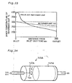
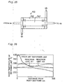
- Fig. 38 is a graph showing a temperature distribution inside the fuel reformer device that receives supplies of oxygen as well as methanol and steam and causes the oxidation reaction to proceed in parallel with the steam reforming reaction.
- Formation of the peak in the temperature distribution or the excessive temperature rise inside the fuel reformer device results in some drawbacks, for example, deterioration of the catalyst and formation of by-products.
- One problem is deterioration of the catalyst.
- a Cu-Zn catalyst is used for the catalyst of accelerating the steam reforming reaction and the oxidation reaction of methanol.
- the use of the Cu-Zn catalyst at high temperatures over 300°C lowers the durability of the catalyst and may cause sintering.
- Sintering is the phenomenon that the catalyst carried on the surface of the carrier aggregates.
- the Cu-Zn catalyst is generally formed by dispersing copper fine particles on the surface of zinc particles. The occurrence of sintering causes the copper fine particles to aggregate and form giant particles. This phenomenon decreases the surface area of the copper particles and reduces the area of the catalytic activity, thereby lowering the performance of the fuel reformer device.
- a side reaction other than the normal reforming reaction discussed above occurs in parallel with the reforming reaction at preset high temperatures to form methane.
- Gaseous nitrogen included in the supply of the pressurized gas undergoes a side reaction to produce nitrogen oxides.
- These by-produces are not decomposed in the temperature range of the reforming reaction in the fuel reformer device, but are supplied to the fuel cells as part of the gaseous fuel.
- An increase in quantity of the by-products like methane unfavorably lowers the hydrogen partial pressure of the gaseous fuel.
- the decrease in internal temperature on the lower stream side of the fuel reformer device disadvantageously lowers the activity of the steam reforming reaction.
- the lowered activity of the steam reforming reaction may cause the non-reformed gas, that is, methanol, to remain and give a resulting gas having an insufficiently low concentration of hydrogen.
- a sufficiently large fuel reformer device is required.
- EP 0798798 (A2 ) is related to the technical field of the present invention. It is described that methanol supplied as a raw fuel is mixed with water, vaporized in an evaporator, and supplied to a reformer as a raw fuel gas.
- the reformer also receives a supply of the compressed air from an air tank.
- the raw fuel gas is mixed with the compressed air in the reformer.
- An oxidation reaction of methanol supplied as the raw fuel proceeds in the reformer to generate hydrogen and carbon dioxide, while a steam reforming reaction of methanol simultaneously proceeds in the reformer to generate hydrogen and carbon dioxide.
- the amount of heat required for the endothermic reforming reaction can be supplied by the oxidation reaction of methanol. No external heat source is accordingly required in the reformer to supply the heat required for the reforming reaction.
- the object of the present invention is thus to solve such drawbacks and to keep the internal temperature of the fuel reformer device within a preset temperature range.
- the present invention is directed to a fuel reformer device according to claim 1 and a process for performing a steam reforming reaction in a fuel reformer device according to claim 3. Further preferred embodiments are defined in the depended claims. The present description further refers to reference fuel reformer devices for explanatory reasons giving background knowledge.
- a first fuel reformer device is described in which a steam reforming reaction, which is endothermic and produces hydrogen from a hydrocarbon and steam, and an oxidation reaction, which is exothermic and oxidizes the hydrocarbon, proceed and heat generated by the oxidation reaction is utilized for a progress of the steam reforming reaction.
- the first fuel reformer device includes: a catalytic section that includes a catalyst for accelerating the steam reforming reaction and the oxidation reaction; a crude fuel gas supply unit that flows a supply of a crude fuel gas containing the hydrocarbon, steam, and oxygen into the catalytic section; a gaseous fuel output unit that causes a hydrogen rich gaseous fuel, which is produced through the steam reforming reaction and the oxidation reaction proceeding in the catalytic section, to be output from the catalytic section; and a gas flow velocity regulation unit that regulates a flow velocity of the crude fuel gas to be higher in an area on a side receiving the supply of the crude fuel gas than in an area on a side outputting the gaseous fuel in the catalytic section, so as to enable the heat generated by the oxidation reaction proceeding in the area on the side receiving the supply of the crude fuel gas to be sufficiently transmitted to the area on the side outputting the gaseous fuel.
- the crude fuel gas containing the hydrocarbon, steam, and oxygen is supplied to the catalytic section including the catalyst for accelerating the steam reforming reaction and the oxidation reaction.
- Both the steam reforming reaction, which is endothermic and produces hydrogen from the hydrocarbon and steam, and the oxidation reaction, which is exothermic and oxidizes the hydrocarbon proceed in the catalytic section.
- the heat generated by the oxidation reaction is utilized for the progress of the steam reforming reaction.
- the resulting hydrogen rich gaseous fuel is output from the catalytic section.
- the flow velocity of the crude fuel gas is regulated to be higher in the area on the side receiving the supply of the crude fuel gas than in the area on the side outputting the gaseous fuel. This enables the heat generated by the oxidation reaction occurring in the area on the side receiving the supply of the crude fuel gas to be sufficiently transmitted to the area on the side outputting the gaseous fuel.
- the heat generated by the oxidation reaction occurring in the area on the side receiving the supply of the crude fuel gas is sufficiently transmitted to the lower stream side.
- This arrangement thus prevents the potential problems due to the excessive temperature rise, that is, deterioration of the catalyst and formation of by-products, and significantly improves the durability of the reformer unit.
- the heat generated by the oxidation reaction is sufficiently transmitted to the area on the side outputting the gaseous fuel. This arrangement ensures the sufficiently high activity of the steam reforming reaction on the lower stream side, thus enabling size reduction of the fuel reformer device.
- the catalyst for accelerating the steam reforming reaction may be identical with or different from the catalyst for accelerating the oxidation reaction. Namely a single catalyst may be used for accelerating both the steam reforming reaction and the oxidation reaction. Different catalysts may alternatively be used for respectively accelerating the steam reforming reaction and the oxidation reaction. In the latter case, it is desirable to sufficiently mix the different catalysts with each other in the reformer unit.
- the gas flow velocity regulation unit makes a total sectional area of a flow path, through which the crude fuel gas flows, smaller on the side receiving the supply of the crude fuel gas than on the side outputting the gaseous fuel in the catalytic section. This arrangement enables the flow velocity of the crude fuel gas to be higher in the area on the side receiving the supply of the crude fuel gas than in the area on the side outputting the gaseous fuel, thereby ensuring the above effects;
- the present description also presents a second fuel reformer device in which a steam reforming reaction, which is endothermic and produces hydrogen from a hydrocarbon and steam, and an oxidation reaction, which is exothermic and oxidizes the hydrocarbon, proceed and heat generated by the oxidation reaction is utilized for a progress of the steam reforming reaction.
- the second fuel reformer device includes: a catalytic section that includes a catalyst for accelerating the steam reforming reaction and the oxidation reaction; a crude fuel gas supply unit that flows a supply of a crude fuel gas containing the hydrocarbon, steam, and oxygen into the catalytic section; and a gaseous fuel output unit that causes a hydrogen rich gaseous fuel, which is produced through the steam reforming reaction and the oxidation reaction proceeding in the catalytic section, to be output from the catalytic section.
- the catalyst in the catalytic section is carried on a carrier mainly composed of a material having a relatively high thermal conductivity.
- the crude fuel gas containing the hydrocarbon, steam, and oxygen is supplied to the catalytic section including the catalyst for accelerating the steam reforming reaction and the oxidation reaction.
- the resulting hydrogen rich gaseous fuel is output from the catalytic section.
- the catalyst is carried on a carrier that is mainly composed of a material having a relatively high thermal conductivity. The heat generated by the oxidation reaction is thus quickly transmitted to the periphery by means of the carrier and is utilized for the steam reforming reaction.
- the heat generated by the oxidation reaction is quickly diffused. This effectively prevents an excessive temperature rise in the area on the side receiving the supply of the crude fuel gas, that is, the area of the vigorous oxidation reaction.
- This arrangement thus prevents the potential problems due to the excessive temperature rise, that is, deterioration of the catalyst and formation of by-products, and significantly improves the durability of the reformer unit.
- the heat generated by the oxidation reaction is diffused and transmitted to the lower stream side. This arrangement ensures the sufficiently high activity of the steam reforming reaction on the lower stream side, thus enabling size reduction of the fuel reformer device.
- the present description further presents a third fuel reformer device in which a steam reforming reaction, which is endothermic and produces hydrogen from a hydrocarbon and steam, and an oxidation reaction, which is exothermic and oxidizes the hydrocarbon, proceed and heat generated by the oxidation reaction is utilized for a progress of the steam reforming reaction.
- the third fuel reformer device includes: a catalytic section that includes a catalyst for accelerating the steam reforming reaction and a catalyst for accelerating the oxidation reaction; a crude fuel gas supply unit that flows a supply of a crude fuel gas containing the hydrocarbon and steam into the catalytic section; an oxidizing gas supply unit that flows a supply of an oxidizing gas containing oxygen into the catalytic section; a gaseous fuel output unit that causes a hydrogen rich gaseous fuel, which is produced through the steam reforming reaction and the oxidation reaction proceeding in the catalytic section, to be output from the catalytic section; and an oxidation reaction suppression unit that suppresses a progress of the oxidation reaction in an area on a side receiving the supply of the oxidizing gas in the catalytic section.
- the crude fuel gas containing the hydrocarbon and steam and the oxidizing gas containing oxygen are supplied to the catalytic section including the catalyst for accelerating the steam reforming reaction and the catalyst for accelerating the oxidation reaction.
- Both the steam reforming reaction which is endothermic and produces hydrogen from the hydrocarbon and steam
- the oxidation reaction which is exothermic and oxidizes the hydrocarbon, proceed in the catalytic section.
- the heat generated by the oxidation reaction is utilized for the progress of the steam reforming reaction.
- the resulting hydrogen rich gaseous fuel is output from the catalytic section. In the catalytic section, the progress of the oxidation reaction is suppressed in the area on the side receiving the supply of the oxidizing gas.
- the progress of the oxidation reaction is suppressed in the area on the side receiving the supply of the oxidizing gas.
- This arrangement thus prevents the potential problems due to the excessive temperature rise, that is, deterioration of the catalyst and formation of by-products, and significantly improves the durability of the reformer unit.
- the suppressed oxidation reaction on the side receiving the supply of the oxidizing gas advantageously extends the area of the vigorous oxidation reaction to the lower stream portion. This heightens the temperature on the lower stream side and ensures the sufficiently high activity of the steam reforming reaction on the lower stream side, thus enabling size reduction of the fuel reformer device.
- the oxidation reaction suppression unit makes an existing quantity of the catalyst for accelerating the oxidation reaction smaller in the area on the side receiving the supply of the oxidizing gas than in an area on a side outputting the gaseous fuel in the catalytic section.
- the catalyst for accelerating the steam reforming reaction is identical with the catalyst for accelerating the oxidation reaction, and that the oxidation reaction suppression unit makes an existing quantity of the identical catalyst smaller in the area on the side receiving the supply of the oxidizing gas than in the area on the side outputting the gaseous fuel.
- the present description also presents a fourth fuel reformer device in which a steam reforming reaction, which is endothermic and produces hydrogen from a hydrocarbon and steam, and an oxidation reaction, which is exothermic and oxidizes the hydrocarbon, proceed and heat generated by the oxidation reaction is utilized for a progress of the steam reforming reaction.
- the fourth fuel reformer device includes: a catalytic section that includes a catalyst for accelerating the steam reforming reaction and a catalyst for accelerating the oxidation reaction; a crude fuel gas supply unit that flows a supply of a crude fuel gas containing the hydrocarbon and steam into the catalytic section; an oxidizing gas supply unit that flows a supply of an oxidizing gas containing oxygen into the catalytic section; a gaseous fuel output unit that causes a hydrogen rich gaseous fuel, which is produced through the steam reforming reaction and the oxidation reaction proceeding in the catalytic section, to be output from the catalytic section; and a reaction state detection unit that detects a degree of progress of the reaction proceeding in the catalytic section.
- the oxidizing gas supply unit has an oxygen concentration regulation unit that keeps a flow rate of oxygen per unit time supplied to the catalytic section at a desired level and regulates a concentration of oxygen included in the oxidizing gas supplied to the catalytic section, based on the degree of progress of the reaction detected by the reaction state detection unit.
- the crude fuel gas containing the hydrocarbon and steam and the oxidizing gas containing oxygen are supplied to the catalytic section including the catalyst for accelerating the steam reforming reaction and the catalyst for accelerating the oxidation reaction.
- Both the steam reforming reaction which is endothermic and produces hydrogen from the hydrocarbon and steam
- the oxidation reaction which is exothermic and oxidizes the hydrocarbon, proceed in the catalytic section.
- the heat generated by the oxidation reaction is utilized for the progress of the steam reforming reaction.
- the resulting hydrogen rich gaseous fuel is output from the catalytic section.
- the degree of progress of the reaction proceeding in the catalytic section is detected. While the flow rate of oxygen per unit time supplied to the catalytic section is kept at a desired level, the concentration of oxygen included in the oxidizing gas supplied to the catalytic section is regulated, based on the detected degree of progress of the reaction.
- the concentration of oxygen included in the oxidizing gas is regulated to control the rate of the oxidation reaction proceeding on the side receiving the supply of the oxidizing gas.
- This arrangement thus prevents the potential problems due to the excessive temperature rise, that is, deterioration of the catalyst and formation of by-products, and significantly improves the durability of the reformer unit.
- the controlled rate of the oxidation reaction through the regulation of the concentration of oxygen included in the oxidizing gas advantageously extends the area of the vigorous oxidation reaction to the lower stream portion. This heightens the temperature on the lower stream side and ensures the sufficiently high activity of the steam reforming reaction on the lower stream side, thus enabling size reduction of the fuel reformer device.
- the catalytic section includes a plurality of reaction units including the catalyst, and that the oxidizing gas supply unit flows the supply of the oxidizing gas into each of the plurality of reaction units.
- the arrangement of receiving the supply of the oxidizing gas at a plurality of places further enhances the effect of homogenizing the temperature inside the catalytic section.
- the present description further presents a fifth fuel reformer device in which a steam reforming reaction, which is endothermic and produces hydrogen from a hydrocarbon and steam, and an oxidation reaction, which is exothermic and oxidizes the hydrocarbon, proceed and heat generated by the oxidation reaction is utilized for a progress of the steam reforming reaction.
- a steam reforming reaction which is endothermic and produces hydrogen from a hydrocarbon and steam
- an oxidation reaction which is exothermic and oxidizes the hydrocarbon
- the fifth fuel reformer device includes: a catalytic section that includes a catalyst for accelerating the steam reforming reaction and the oxidation reaction; a crude fuel gas supply unit that flows a supply of a crude fuel gas containing the hydrocarbon, steam, and oxygen into the catalytic section; a gaseous fuel output unit that causes a hydrogen rich gaseous fuel, which is produced through the steam reforming reaction and the oxidation reaction proceeding in the catalytic section, to be output from the catalytic section; and a gas flow direction inversion unit that changes a site receiving the supply of the crude fuel gas by means of the crude fuel gas supply unit and a site outputting the gaseous fuel by means of the gaseous fuel output unit with each other in the catalytic section, so as to invert a gas flow in the catalytic section.
- the crude fuel gas containing the hydrocarbon, steam, and oxygen is supplied to the catalytic section including the catalyst for accelerating the steam reforming reaction and the oxidation reaction.
- Both the steam reforming reaction which is endothermic and produces hydrogen from the hydrocarbon and steam
- the oxidation reaction which is exothermic and oxidizes the hydrocarbon, proceed in the catalytic section.
- the heat generated by the oxidation reaction is utilized for the progress of the steam reforming reaction.
- the resulting hydrogen rich gaseous fuel is output from the catalytic section.
- the site receiving the supply of the crude fuel gas is changed with the site outputting the gaseous fuel in the catalytic section.
- the site receiving the supply of the crude fuel gas is changed with the site outputting the gaseous fuel in the catalytic section.
- This arrangement thus prevents the potential problems due to the excessive temperature rise, that is, deterioration of the catalyst and formation of by-products, and significantly improves the durability of the reformer unit.
- the catalytic section has an end temperature measurement unit that measures a temperature at a preset position in the site receiving the supply of the crude fuel gas by means of the crude fuel gas supply unit in the catalytic section, and that the gas flow direction inversion unit changes the site receiving the supply of the crude fuel gas by means of the crude fuel gas supply unit and the site outputting the gaseous fuel by means of the gaseous fuel output unit with each other, based on the observed temperature by the end temperature measurement unit.
- This arrangement effectively prevents the excessive temperature rise on the side receiving the crude fuel gas.
- the present description also presents a sixth fuel reformer device in which a steam reforming reaction, which is endothermic and produces hydrogen from a hydrocarbon and steam, and an oxidation reaction, which is exothermic and oxidizes the hydrocarbon, proceed and heat generated by the oxidation reaction is utilized for a progress of the steam reforming reaction.
- the sixth fuel reformer device includes: a catalytic section which particles with a catalyst for accelerating the steam reforming reaction and the oxidation reaction are sealed in; a crude fuel gas supply unit that flows a supply of a crude fuel gas containing the hydrocarbon, steam, and oxygen into the catalytic section; a gaseous fuel output unit that causes a hydrogen rich gaseous fuel, which is produced through the steam reforming reaction and the oxidation reaction proceeding in the catalytic section, to be output from the catalytic section; and a catalyst stirrer unit that stirs the particles with the catalyst in the catalytic section.
- the crude fuel gas containing the hydrocarbon, steam, and oxygen is supplied to the catalytic section that is filled with the particles with the catalyst for accelerating the steam reforming reaction and the oxidation reaction.
- Both the steam reforming reaction, which is endothermic and produces hydrogen from the hydrocarbon and steam, and the oxidation reaction, which is exothermic and oxidizes the hydrocarbon proceed in the catalytic section, while the particles with the catalyst are stirred.
- the heat generated by the oxidation reaction is utilized for the progress of the steam reforming reaction.
- the resulting hydrogen rich gaseous fuel is output from the catalytic section.
- the particles with the catalyst are stirred in the catalytic section.
- the catalyst carried on the particles is thus successively involved in the oxidation reaction.
- This arrangement thus prevents the potential problems due to the excessive temperature rise, that is, deterioration of the catalyst and formation of by-products, and significantly improves the durability of the reformer unit.
- the catalyst stirrer unit is disposed in the crude fuel gas supply unit and injects a gas containing at least one of the hydrocarbon, steam, and oxygen into the catalytic section, so as to stir the particles with the catalyst in the catalytic section.
- This arrangement enables the action of supplying the crude fuel gas to the catalytic section to be carried out simultaneously with the action of stirring the particles with the catalyst.
- the present description also presents a seventh fuel reformer device in which a steam reforming reaction, which is endothermic and produces hydrogen from a hydrocarbon and steam, and an oxidation reaction, which is exothermic and oxidizes the hydrocarbon, proceed and heat generated by the oxidation reaction is utilized for a progress of the steam reforming reaction.
- the seventh fuel reformer device includes: a catalytic section' that includes a catalyst for accelerating the steam reforming reaction and the oxidation reaction; a crude fuel gas supply unit that flows a supply of a crude fuel gas containing the hydrocarbon and steam into the catalytic section; an oxidizing gas supply unit that flows a supply of an oxidizing gas containing oxygen into the catalytic section; a gaseous fuel output unit that causes a hydrogen rich gaseous fuel, which is produced through the steam reforming reaction and the oxidation reaction proceeding in the catalytic section, to be output from the catalytic section; and a flow site changing unit that changes with time a site receiving the supply of the oxidizing gas by means of the oxidizing gas supply unit in the catalytic section.
- the crude fuel gas containing the hydrocarbon and steam and the oxidizing gas containing oxygen are supplied to the catalytic section including the catalyst for accelerating the steam reforming reaction and the oxidation reaction.
- Both the steam reforming reaction which is endothermic and produces hydrogen from the hydrocarbon and steam
- the oxidation reaction which is exothermic and oxidizes the hydrocarbon, proceed in the catalytic section.
- the site receiving the supply of the oxidizing gas is changed with time in the catalytic section.
- the heat generated by the oxidation reaction that proceeds with the oxidizing gas supplied in this manner is utilized for the progress of the steam reforming reaction.
- the resulting hydrogen rich gaseous fuel is output from the catalytic section.
- the site receiving the supply of the oxidizing gas is changed with time in the catalytic section. This effectively prevents an excessive temperature rise in a specific area on the side receiving the supply of the oxidizing gas.
- This arrangement thus prevents the potential problems due to the excessive temperature rise, that is, deterioration of the catalyst and formation of by-products, and significantly improves the durability of the reformer unit.
- the present description further presents an eighth fuel reformer device in which a steam reforming reaction, which is endothermic and produces hydrogen from a hydrocarbon and steam, and an oxidation reaction, which is exothermic and oxidizes the hydrocarbon, proceed and heat generated by the oxidation reaction is utilized for a progress of the steam reforming reaction.
- the eighth fuel reformer device includes: a catalytic section that includes a catalyst for accelerating the steam reforming reaction and the oxidation reaction; a crude fuel gas supply unit that flows a supply of a crude fuel gas containing the hydrocarbon and steam into the catalytic section; an oxidizing gas supply unit that flows a supply of an oxidizing gas containing oxygen into the catalytic section; a gaseous fuel output unit that causes a hydrogen rich gaseous fuel, which is produced through the steam reforming reaction and the oxidation reaction proceeding in the catalytic section, to be output from the catalytic section; and a heat homogenization unit that makes a feeding side receiving the supply of the crude fuel gas and the supply of the oxidizing gas adjoin to an output side outputting the gaseous fuel in the catalytic section, so as to enable heat exchange between the feeding side and the output side.
- the crude fuel gas containing the hydrocarbon and steam and the oxidizing gas containing oxygen are supplied to the catalytic section including the catalyst for accelerating the steam reforming reaction and the oxidation reaction.
- Both the steam reforming reaction, which is endothermic and produces hydrogen from the hydrocarbon and steam, and the oxidation reaction, which is exothermic and oxidizes the hydrocarbon proceed in the catalytic section.
- the feeding side receiving the supply of the crude fuel gas and the supply of the oxidizing gas is arranged to be adjacent to the output side outputting the gaseous fuel. Heat exchange is accordingly performed between the feeding side and the output side. The heat generated by the oxidation reaction is thus utilized for the progress of the steam reforming reaction.
- the resulting hydrogen rich gaseous fuel is output from the catalytic section.
- the catalytic section includes at least two reaction units that respectively include the catalyst and have the feeding side and the output side mutually located at opposite positions, and that the at least two reaction units are arranged to make the feeding side of one reaction unit adjacent to the output side of the other reaction unit.
- the catalytic section includes a turning area in a flow conduit of the crude fuel gas formed inside thereof, and that an inlet and an outlet of the flow conduit are arranged to be adjacent to each other.
- the present description further presents a ninth fuel reformer device in which a steam reforming reaction, which is endothermic and produces hydrogen from a hydrocarbon and steam, and an oxidation reaction, which is exothermic and oxidizes the hydrocarbon, proceed and heat generated by the oxidation reaction is utilized for a progress of the steam reforming reaction.
- the ninth fuel reformer device includes: a catalytic section that includes a catalyst for accelerating the steam reforming reaction and the oxidation reaction; a crude fuel gas supply unit that flows a supply of a crude fuel gas containing the hydrocarbon and steam into the catalytic section; an oxidizing gas supply unit that flows a supply of an oxidizing gas containing oxygen into the catalytic section; a gaseous fuel output unit that causes a hydrogen rich gaseous fuel, which is produced through the steam reforming reaction and the oxidation reaction proceeding in the catalytic section, to be output from the catalytic section; and a heating unit that heats a part other than an area on a side receiving the supply of the oxidizing gas by means of a specific fluid that transmits heat produced in a predetermined member, which is a constituent of a system including the fuel reformer device.
- the crude fuel gas containing the hydrocarbon and steam and the oxidizing gas containing oxygen are supplied to the catalytic section including the catalyst for accelerating the steam reforming reaction and the oxidation reaction.
- the heat generated by the oxidation reaction is utilized for the progress of the steam reforming reaction.
- the heat produced in the predetermined member which is the constituent of the system including the fuel reformer device, is transmitted to the part other than the area on the side receiving the supply of the oxidizing gas by means of the specific fluid, and is utilized for the steam reforming reaction.
- the resulting hydrogen rich gaseous fuel is output from the catalytic section.
- the oxidation reaction proceeds with the heat evolved in the predetermine member, which is the constituent of the system including the fuel reformer device.
- This arrangement enables the flow rate of the oxidizing gas supplied to the catalytic section to be reduced relative to the flow rate of the crude fuel gas supplied to the catalytic section. This effectively prevents an excessive temperature rise in a specific area on the side receiving the supply of the oxidizing gas. This arrangement thus prevents the potential problems due to the excessive temperature rise, that is, deterioration of the catalyst and formation of by-products, and significantly improves the durability of the reformer unit.
- the heat evolved in the predetermined member which is the constituent of the system including the fuel reformer device, is transmitted to the part other than the area on the side receiving the supply of the oxidizing gas. There is accordingly no significant temperature drop to lower the activity of the steam reforming reaction. This ensures the sufficiently high activity of the steam reforming reaction in the whole catalytic section, thus enabling size reduction of the fuel reformer device.
- This structure utilizes the heat evolved in the predetermined member, which is the constituent of the system including the fuel reformer device, to heat the part other than the area on the side receiving the supply of the oxidizing gas, thus effectively preventing a decrease in energy efficiency of the whole system.
- the heating unit heats the part other than the area on the side receiving the supply of the oxidizing gas by means of a hot gas discharged from the predetermined member, which is the constituent of the system including the fuel reformer device.
- the present invention is directed to a tenth fuel reformer device in which a steam reforming reaction, which is endothermic and produces hydrogen from a hydrocarbon and steam, and an oxidation reaction, which is exothermic and oxidizes the hydrocarbon, proceed and heat generated by the oxidation reaction is utilized for a progress of the steam reforming reaction.
- the tenth fuel reformer device includes: a catalytic section that includes a catalyst for accelerating the steam reforming reaction and the oxidation reaction; a crude fuel gas supply unit that flows a supply of a crude fuel gas containing the hydrocarbon and steam into the catalytic section; an oxidizing gas supply unit that flows a supply of an oxidizing gas containing oxygen into the catalytic section; a gaseous fuel output unit that causes a hydrogen rich gaseous fuel, which is produced through the steam reforming reaction and the oxidation reaction proceeding in the catalytic section, to be output from the catalytic section; and an end cooling unit that sprays a liquid containing at least one of the hydrocarbon and water into an area on a side receiving the supply of the crude fuel gas and the supply of the oxidizing gas.
- the crude fuel gas containing the hydrocarbon and steam and the oxidizing gas containing oxygen are supplied to the catalytic section including the catalyst for accelerating the steam reforming reaction and the oxidation reaction.
- the heat generated by the oxidation reaction is utilized for the progress of the steam reforming reaction.
- the liquid containing at least one of the hydrocarbon and water is sprayed into the area on the side receiving the supply of the crude fuel gas and the supply of the oxidizing gas, so as to cool down the area.
- the resulting hydrogen rich gaseous fuel is output from the catalytic section.
- the liquid containing at least one of the hydrocarbon and water is sprayed into the area on the side receiving the supply of the crude fuel gas and the supply of the oxidizing gas. Part of the heat generated by the oxidation reaction is accordingly consumed as the heat of vaporization. This effectively prevents an excessive temperature rise in a specific area on the side receiving the supply of the oxidizing gas. This arrangement thus prevents the potential problems due to the excessive temperature rise, that is, deterioration of the catalyst and formation of by-products, and significantly improves the durability of the reformer unit.
- the present description further presents an eleventh fuel reformer device in which a steam reforming reaction, which is endothermic and produces hydrogen from a hydrocarbon and steam, and an oxidation reaction, which is exothermic and oxidizes the hydrocarbon, proceed and heat generated by the oxidation reaction is utilized for a progress of the steam reforming reaction.
- the eleventh fuel reformer device includes: a catalytic section that comprises a first reaction unit including a catalyst for accelerating the steam reforming reaction and the oxidation reaction and a second reaction unit including a catalyst for accelerating the steam reforming reaction; a crude fuel gas supply unit that flows a supply of a crude fuel gas containing the hydrocarbon and steam into the catalytic section; an oxidizing gas supply unit that flows a supply of an oxidizing gas containing oxygen into the first reaction unit; and a gaseous fuel output unit that causes a hydrogen rich gaseous fuel, which is produced through the steam reforming reaction and the oxidation reaction proceeding in the catalytic section, to be output from the catalytic section.
- the first reaction unit and the second reaction unit are arranged to be adjacent to each other in the catalytic section, and heat exchange is performed between the first reaction unit and the second reaction unit.
- the crude fuel gas containing the hydrocarbon and steam and the oxidizing gas containing oxygen are supplied to the first reaction unit including the catalyst for accelerating the steam reforming reaction and the oxidation reaction.
- Both the steam reforming reaction which is endothermic and produces hydrogen from the hydrocarbon and steam, and the oxidation reaction, which is exothermic and oxidizes the hydrocarbon, proceed in the first reaction unit.
- the crude fuel gas is also supplied to the second reaction unit including the catalyst for accelerating the steam reforming reaction.
- the steam reforming reaction then also proceeds in the second reaction unit.
- the heat generated by the oxidation reaction is utilized for the progress of the steam reforming reaction.
- the heat exchange performed between the second reaction unit and the adjoining first reaction unit enables the heat generated by the oxidation reaction in the first reaction unit to be utilized for the progress of the steam reforming reaction in the second reaction unit.
- the resulting hydrogen rich gaseous fuel is output from the catalytic section.
- the heat generated by the oxidation reaction in the area of the first reaction unit where the oxidation reaction proceeds with the supply of the oxidizing gas is not only utilized for the steam reforming reaction proceeding in the first reaction unit but transmitted to the adjoining second reaction unit and utilized for the steam reforming reaction proceeding in the second reaction unit.
- This arrangement effectively prevents the potential problems due to an excessive temperature rise in the catalytic section with the heat generated by the oxidation reaction, that is, deterioration of the catalyst and formation of by-products, and significantly improves the durability of the reformer unit.
- the hydrocarbon may be methanol
- the catalyst for accelerating the steam reforming reaction and the oxidation reaction may be a single copper-containing catalyst.
- the hydrocarbon may be methanol
- the catalyst for accelerating the steam reforming reaction and the catalyst for accelerating the oxidation reaction may be an identical copper-containing catalyst.
- the hydrocarbon may be methanol
- the catalyst included in the first reaction unit may be a single copper-containing catalyst.
- the single copper-containing catalyst is used to accelerate both the steam reforming reaction and the oxidation reaction of methanol.
- the oxidation reaction of methanol proceeding in the presence of the copper-containing catalyst hardly produces carbon monoxide. This arrangement accordingly gives the resulting gaseous fuel having the lower concentration of carbon monoxide.
- the present description also presents a twelfth fuel reformer device in which a steam reforming reaction, which is endothermic and produces hydrogen from a hydrocarbon and steam, and an oxidation reaction, which is exothermic and oxidizes the hydrocarbon, proceed and heat generated by the oxidation reaction is utilized for a progress of the steam reforming reaction.
- the twelfth fuel reformer device includes: a catalytic section that includes a catalyst for accelerating the steam reforming reaction and the oxidation reaction; a crude fuel gas supply unit that flows a supply of a crude fuel gas containing the hydrocarbon, steam, and oxygen into the catalytic section; and a gaseous fuel output unit that causes a hydrogen rich gaseous fuel, which is produced through the steam reforming reaction and the oxidation reaction proceeding in the catalytic section, to be output from the catalytic section.
- the catalyst accelerates the oxidation reaction that is not via a reaction pathway of producing carbon monoxide.
- the catalyst accelerates the oxidation reaction that is not via the reaction pathway of producing carbon monoxide.
- This arrangement effectively reduces the quantity of carbon monoxide produced by the reactions proceeding in the catalytic section, thus giving the resulting gaseous fuel having the lower concentration of carbon monoxide.
- the hydrocarbon may be methanol
- the catalyst for accelerating the - steam reforming reaction and the oxidation reaction may be a single copper-containing catalyst.
- the copper-containing catalyst is used to accelerate the oxidation reaction of methanol.
- the oxidation reaction proceeding in the presence of the copper-containing catalyst hardly produces carbon monoxide.
- This arrangement accordingly gives the resulting gaseous fuel having the lower concentration of carbon monoxide.
- Fig. 1 schematically illustrates the structure of a fuel cells system 20 including a reformer unit in a first embodiment.
- the fuel cells system 20 includes, as primary constituents, a methanol reservoir 22 that stores methanol therein, a water reservoir 24 that stores water therein, a burner 26 that generates a combustion gas, a compressor unit 28 that compresses the air, an evaporator 32 that is coupled with the burner 26 and the compressor unit 28, a reformer unit 34 that produces a gaseous fuel through a reforming reaction, a CO reduction unit 36 that reduces concentration of carbon monoxide (CO) included in the gaseous fuel, fuel cells 40 that generate an electromotive force through electrochemical reactions, and a control unit 50 that is constructed by a computer.
- CO carbon monoxide
- the fuel cells 40 which mainly function to generate electric power in the fuel cells system 20.
- the fuel cells 40 are polymer electrolyte fuel cells and have a stack structure obtained by laying a plurality of construction units or unit cells one upon another.
- Fig. 2 is a sectional view illustrating the structure of a unit cell 48 of the fuel cells stack 40.
- the unit cell 48 includes an electrolyte membrane 41, an anode 42, a cathode 43, and a pair of separators 44 and 45.
- the anode 42 and the cathode 43 are gas diffusion electrodes that are disposed across the electrolyte membrane 41 to form a sandwich structure.
- the pair of separators 44 and 45 are further disposed across this sandwich structure and are respectively combined with the anode 42 and the cathode 43 to define flow paths of a gaseous fuel and an oxidizing gas.
- Gaseous fuel flow conduits 44P are defined by the anode 42 and the separator 44
- oxidizing gas flow conduits 45P are defined by the cathode 43 and the separator 45.
- One face of the separator is combined with the anode 42 to define the gaseous fuel flow conduits 44P, whereas the other face of the separator is combined with the cathode 43 of the adjoining unit cell to define the oxidizing gas flow conduits 45P.
- the separators 44 and 45 are combined with the adjoining gas diffusion electrodes to define the gas flow conduits, while functioning to separate the flow of gaseous fuel from the flow of oxidizing gas between each pair of adjoining unit cells.
- the two separators located on both ends of the stack structure may have ribs only in the respective single faces thereof that are in contact with the gas diffusion electrodes.
- the electrolyte membrane 41 is a proton-conductive ion exchange membrane composed of a solid polymer material, for example, a fluororesin, and shows favorable electrical conductivity in the wet state.
- a Nafion (manufactured by du Pont) film is applied for the electrolyte membrane 41.
- Platinum or a platinum alloy consisting of platinum and another metal is applied as a catalyst on the surface of the electrolyte membrane 41.
- the anode 42 and the cathode 43 are made of carbon cloth that is woven of carbon fiber yarns.
- the anode 42 and the cathode 43 may be made of carbon paper or carbon felt that also consists of carbon fibers, instead of the carbon cloth of this embodiment.
- the separators 44 and 45 are composed of a gas-impermeable electrically conductive material, for example, gas-impermeable dense carbon obtained by compacting carbon powder.
- Each of the separators 44 and 45 has a plurality of ribs that are arranged in parallel on both faces thereof and are combined with the surface of the anode 42 to define the gaseous fuel flow conduits 44P while being combined with the surface of the cathode 43 of the adjoining unit cell to define the oxidizing gas flow conduits 45P.
- the ribs formed on one face may be arranged at a predetermined angle to the ribs formed on the other face, for example, parallel to the ribs on the other face.
- the shape of the ribs may not be restricted to the parallel grooves, but the ribs may have any shape that allow supplies of the gaseous fuel and the oxidizing gas to the gas diffusion electrodes.
- the unit cell 48 which is the construction unit of the fuel cells 40, has the structure discussed above.
- plural sets (100 sets in this embodiment) of the unit cells 48 each including the separator 44, the anode 42, the electrolyte membrane 41, the cathode 43, and the separator 45 in this sequence, are laid one upon another to form a cell laminate.
- the stack structure is completed by arranging a pair of collector plates, which are composed of dense carbon or copper plates, across the cell laminate.
- the constituents of the fuel cells system 20 other than the fuel cells 40 and their connections are discussed below.
- the evaporator 32 receives supplies of methanol and water from the methanol reservoir 22 and the water reservoir 24 and vaporize the methanol and water.
- the evaporator 32 is coupled with the burner 26 and the compressor unit 28 as mentioned previously.
- a combustion exhaust discharged from the burner 26 is led via the compressor unit 28 as discussed later, and the heat of combustion is transmitted to a non-illustrated heat exchange unit of the evaporator 32 to boil and vaporize methanol and water supplied to the evaporator 32.
- a second pump 71 is disposed in a methanol flow conduit 60, through which a supply of methanol as a crude fuel is flown from the methanol reservoir 22 to the evaporator 32, in order to regulate the quantity of methanol supplied to the evaporator 32.
- the second pump 71 is connected with the control unit 50 and is driven in response to signals output from the control unit 50 to regulate the flow rate of methanol supplied to the evaporator 32.
- a third pump 72 is disposed in a water flow conduit 62, through which a supply of water is flown from the water reservoir 24 to the evaporator 32, in order to regulate the quantity of water supplied to the evaporator 32.
- the third pump 72 is connected with the control unit 50 and is driven in response to signals output from the control unit 50 to regulate the flow rate of water supplied to the evaporator 32.
- the methanol flow conduit 60 joins the water flow conduit 62 to form a first fuel supply conduit 63, which connects with the evaporator 32.
- the mixture of a preset quantity of the methanol and a preset quantity of water is fed to the evaporator 32 via the fist fuel supply conduit 63.
- the compressor unit 28 coupled with the evaporator 32 takes in the air from the outside of the fuel cells system 20, compresses the intake air, and feeds the compressed air to the cathodes of the fuel cells 40.
- the compressor unit 28 includes a turbine 28a and a compressor 28b formed in an impeller.
- the turbine 28a and the compressor 28b are linked with each other via a coaxial shaft 28c.
- the compressor 28b is driven and rotated by driving and rotating the turbine 28a.
- the burner 26 is also coupled with the evaporator 32.
- the turbine 28a is driven by the hot combustion gas led from this burner 26.
- the compressor 28b rotates with the rotation of the turbine 28a and compresses the air as mentioned previously.
- the air is taken from the outside into the compressor 28b via an air flow conduit 29.
- the air compressed by the compressor unit 28 is fed to the fuel cells 40 via an oxidizing gas supply conduit 68 and is subjected to the electrochemical reactions proceeding in the fuel cells 40.
- the turbine 28a is actuated by the hot combustion gas led from the burner 26 and is composed of a refractory alloy or ceramic to have the heat resistance and durability.
- a nickel-based alloy (Inconel 700 manufactured by Inconel Corporation) is used for the turbine 28a.
- the compressor 28b is composed of a light-weight aluminum alloy.
- the burner 26 that functions to drive the turbine 28a receives the fuel for combustion from the anodes of the fuel cells 40 and the methanol reservoir 22.
- the fuel cells 40 use, as the fuel, a hydrogen rich gas produced by reforming methanol in the reformer unit 34 for the electrochemical reactions proceeding therein. All the hydrogen supplied to the fuel cells 40 is not consumed by the electrochemical reactions, but a gaseous fuel exhaust including the non-consumed, remaining hydrogen is discharged to a fuel exhaust conduit 67.
- the burner 26 connected to this fuel exhaust conduit 67 receives a supply of the gaseous fuel exhaust and causes the non-consumed, remaining hydrogen to undergo the complete combustion, so as to improve the utilization rate of the fuel.
- the fuel exhaust is generally not sufficient for the fuel for combustion in the burner 26.
- a supply of methanol is accordingly fed from the methanol reservoir 22 to the burner 26 to supplement such an insufficiency or to be used as the fuel for combustion in the burner 26 when no fuel exhaust is fed from the fuel cells 40, for example, at the starting time of the fuel cells system 20.
- a methanol branch conduit 61 is formed to feed the supply of methanol to the burner 26.
- the methanol branch conduit 61 branches off from the methanol flow conduit 60, through which the supply of methanol is flown from the methanol reservoir 22 to the evaporator 32.
- the burner 26 has a first temperature sensor 73 that measures the temperature of combustion in the burner 26 and inputs the result of the measurement to the control unit 50.
- the control unit 50 outputs a driving signal to the first pump 70 based on the input from the first temperature sensor 73, so as to regulate the quantity of methanol fed to the burner 26 and maintain the temperature of combustion in the burner 26 within a predetermined range (approximately 800°C to 1000°C).
- the combustion gas in the burner 26 works to drive and rotate the turbine 28a and is then led to the evaporator 32.
- the efficiency of heat exchange in the turbine 28a is relatively low (not higher than approximately 10%).
- the combustion exhaust gas led to the evaporator 32 accordingly has the temperature of approximately 600 to 700°C and is sufficient for the heat source of the evaporator 32.
- the solution mixture of methanol and water supplied via the first fuel supply conduit 63 as described previously is vaporized by the hot combustion exhaust gas led from the burner 26 to the evaporator 32.
- a crude fuel gas of methanol and water vaporized by the evaporator 32 is flown through a second fuel supply conduit 64 to the reformer unit 34.
- the reformer unit 34 reforms the crude fuel gas of methanol and water to produce a hydrogen rich gaseous fuel.
- the configuration of the reformer unit 34 and the reforming reaction proceeding in the reformer unit 34 are the essential part and will be discussed in detail later.
- a second temperature sensor 74 is disposed in the second fuel supply conduit 64, through which the crude fuel gas of methanol and water is flown to the reformer unit 34, and measures the temperature of the crude fuel gas of methanol and water fed to the reformer unit 34. The observed temperature of the crude fuel gas is input into the control unit 50.
- the control unit 50 corrects the driving amount of the first pump 70 based on the input from the second temperature sensor 74 and regulates the quantity of methanol fed to the burner 26. Regulating the temperature of the combustion gas in the burner 26 in this manner adjusts the temperature of the crude fuel gas vaporized in the evaporator 32.
- the crude fuel gas led from the evaporator 32 is generally heated to approximately 250°C.
- the reformer unit 34 has a blower 38 to taken in oxygen required for the reforming reaction.
- the blower 38 compresses the externally intake air and feeds the compressed intake air to the reformer unit 34 via an air supply conduit 39.
- the air supply conduit 39 joins the second fuel supply conduit 64, and the intake air by the blower 38 is fed into the reformer unit 34 together with the crude fuel gas led from the evaporator 32.
- the blower 38 is connected with the control unit 50, which controls the driving state of the blower 38.
- the CO reduction unit 36 reduces the concentration of carbon monoxide included in the gaseous fuel led from the reformer unit 34 via a third fuel supply conduit 65.
- the general reforming reaction of methanol is expressed by Equation (4) given previously. In the actual state, however, the reforming reaction does not proceed in the ideal manner as expressed by this equation, but the gaseous fuel produced in the reformer unit 34 includes a certain amount of carbon monoxide.
- the CO reduction unit 36 functions to reduce the concentration of carbon monoxide included in the gaseous fuel supplied to the fuel cells 40.
- the fuel cells 40 of this embodiment are polymer electrolyte fuel cells and have the platinum or platinum alloy catalyst to accelerate the cell reactions (in this embodiment, the platinum catalyst is applied on the surface of the electrolyte membrane 41). Carbon monoxide included in the gaseous fuel is adsorbed by the platinum catalyst to lower its catalytic action and interfere with the reaction of Equation (1) proceeding at the anodes, so as to deteriorate the performance of the fuel cells.
- the allowable limit of the concentration of carbon monoxide included in the supply of gaseous fuel is generally not greater than several ppm.
- the gaseous fuel led to the CO reduction unit 36 is a hydrogen rich gas containing the certain amount of carbon monoxide as mentioned above.
- the CO reduction unit 36 oxidizes carbon monoxide in preference to hydrogen included in the gaseous fuel.
- the CO reduction unit 36 is filled with a carrier having any of platinum, ruthenium, palladium, gold, and alloys of these metals as the primary element carried thereon as a carbon monoxide selective oxidation catalyst.
- the concentration of carbon monoxide included in the gaseous fuel processed by this CO reduction unit 36 depends upon the driving temperature of the CO reduction unit 36, the concentration of carbon monoxide originally included in the supply of gaseous fuel, and the flow rate of the gaseous fuel fed to the CO reduction unit 36 per unit volume of the catalyst.
- the CO reduction unit 36 has a non-illustrated carbon monoxide sensor.
- the driving temperature of the CO reduction unit 36 and the flow rate of the gaseous fuel fed to the CO reduction unit 36 are regulated according to the result of the measurement with the carbon monoxide sensor, so as to make the concentration of carbon monoxide included in the processed gaseous fuel not greater than several ppm.
- the gaseous fuel having the reduced concentration of carbon monoxide is led from the CO reduction unit 36 through a fourth fuel supply conduit 66 to the fuel cells 40 and is subjected to the cell reaction at the anodes.
- the gaseous fuel exhaust after the cell reaction in the fuel cells 40 is discharged to the fuel exhaust conduit 67 and led to the burner 26 as mentioned previously.
- the remaining hydrogen in the gaseous fuel exhaust is consumed as the fuel for combustion.
- the oxidizing gas involved in the cell reaction at the cathode of the fuel cells 40 is supplied as the compressed air from the compressor unit 28 through the oxidizing gas supply conduit 68 as described above.
- the oxidizing gas exhaust after the cell reaction is discharged outside via an oxidizing gas exhaust conduit 69.
- the control unit 50 is constructed as a logic circuit including a microcomputer.
- the control unit 50 includes a CPU 54 that executes a variety of arithmetic and logic operations according to preset control programs, a ROM 56 in which control programs and control data required for the execution of the various arithmetic and logic operations by the CPU 54 are stored in advance, a RAM 58 which a diversity of data required for the execution of the various arithmetic and logic operations by the CPU 54 are temporarily written in and read from, and an input-output port 52 that inputs detection signals from the temperature sensors described above and outputs driving signals to the pumps and the blower 38 described above according to the results of the arithmetic and logic operations executed by the CPU 54.
- Fig. 3 schematically illustrates the structure of the reformer unit 34.
- the reformer unit 34 of this embodiment receives the supplies of the crude fuel gas and the air from an end connecting with the second fuel supply conduit 64.
- the supplied crude fuel gas and the air pass through the inside of the reformer unit 34 and are subjected to the steam reforming reaction and the oxidation reaction (the partial oxidation reaction).
- the hydrogen rich gaseous fuel produced through the steam reforming reaction expressed by Equation (4) and the oxidation reaction expressed by Equation (5) in the reformer unit 34 is discharged from the other end to the third fuel supply conduit 65.
- the reformer unit 34 includes a first reaction unit 80 and a second reaction unit 81.
- the first reaction unit 80 and the second reaction unit 81 are constructed as metal honeycombs with a Cu-Zn catalyst carried on the surface thereof.
- the first reaction unit 80 disposed on the upper stream side (that is, the side close to the connection with the second fuel supply conduit 64) is designed to have a smaller number of cells discussed later than the second reaction unit 81 disposed on the lower stream side (that is, the side close to the connection with the third fuel supply conduit 65).
- Fig. 4 schematically illustrates part of the cross section of the metal honeycomb that defines the first reaction unit 80 and the second reaction unit 81.
- the metal honeycomb is formed by laying stainless steel plates 82 and 83 one upon the other. More specifically the metal honeycomb is formed by alternately laying the flat stainless steel plates 82 and the corrugated stainless steel plates 83 one upon another.
- the stainless steel plate 83 is corrugated at the intervals of 1 mm.
- the alternate arrangement of the corrugated stainless steel plates 83 and the flat stainless steel-plates 82 accordingly gives the honeycomb structure of cells having a substantially square cross section of 1 mm in length of each side.
- the difference between the first reaction unit 80 and the second reaction unit 81 is the thickness of the stainless steel plates 82 and 83 used to form the metal honeycomb structure.
- the different thickness results in a difference between the number of cells included in the first reaction unit 80 and the number of cells included in the second reaction unit 81.
- the first reaction unit 80 has the honeycomb structure formed by the stainless steel plates 82 and 83 of 0.1 mm in thickness
- the second reaction unit 81 has the honeycomb structure formed by the stainless steel plates 82 and 83 of 0.03 mm in thickness.
- the first reaction unit 80 includes about 75 cells per 1 cm2 of the cross section
- the second reaction unit 81 includes about 91 cells per 1 cm2 of the cross section.
- the reformer unit 34 has a fixed cross section.
- honeycomb structures composed of the stainless steel plates of different thicknesses accordingly make the total sectional area of the gas flow path in the first reaction unit 80 (that is, the sum of the cross sections of the respective cells included in the first reaction unit 80) smaller than the total sectional area of the gas flow path in the second reaction unit 81 (that is, the sum of the cross sections of the respective cells included in the second reaction unit 80).
- the catalyst is respectively carried on the surface of the honeycomb structures of the first reaction unit 80 and the second reaction unit 82.
- the flow of the crude fuel gas passing through the surface of the honeycomb structures is subjected to the steam reforming reaction and the oxidation reaction to produce a hydrogen rich gaseous fuel.
- the catalyst carried on the surface of the honeycomb structure is manufactured from copper and zinc oxide by coprecipitation.
- the Cu-Zn catalyst obtained by coprecipitation is crushed, is mixed with a binder like an alumina sol, and is carried on the surface of the honeycomb, for example, by application.
- the flow of the crude fuel gas fed to the reformer unit 34 constructed as discussed above first passes through the first reaction unit 80 having the less number of cells, that is, having the smaller total sectional area of the gas flow path, and then the second reaction unit 81 having the greater number of cells, that is, having the greater total sectional area of the gas flow path. Since the preset flow rate of the crude fuel gas passes through the honeycomb structure having the smaller total sectional area of the gas flow path and the honeycomb structure having the greater total sectional area of the gas flow path in this sequence, the flow velocity of the crude fuel gas is higher in the first reaction unit 80 of the reformer unit 34 than in the second reaction unit 81.
- Fig. 5 is a graph showing the internal temperature distributions along the flow of the gas with regard to the reformer unit 34 of this embodiment and a prior art reformer unit having a fixed cross section of the honeycomb structure.
- the oxidation reaction has the higher reaction rate than the steam reforming reaction.
- the oxidation reaction vigorously proceeds in the vicinity of the inlet of the crude fuel gas. This raises the temperature to approximately 400°C in the neighborhood of the inlet.
- the crude fuel gas has the high flow velocity on the upstream side, so that the heat produced by the oxidation reaction proceeding on the upstream side is quickly transmitted to the downstream portion by the fast flow of the gas.
- the higher flow velocity of the crude fuel gas on the upstream side prevents the oxidation reaction from being completed in a narrow area on the upstream side but extends the area of the vigorous oxidation reaction to the lower stream portion. This effectively prevents an abrupt temperature rise in the neighborhood of the inlet.
- the first reaction unit 80 disposed on the upper stream side has the honeycomb structure formed by the thick stainless steel plates and accordingly has a large heat capacity. The heat generated by the oxidation reaction thus tends to be transmitted to the lower stream portion by the flow of the gas, prior to be transmitted to the honeycomb structure and increase the temperature of the honeycomb structure.
- the reformer unit 34 of this embodiment there is no abrupt temperature rise in the vicinity of the inlet. This advantageously prevents the potential troubles due to the temperature rise, for example, deterioration of the catalyst and formation of by-products.
- the reduced deterioration of the catalyst significantly improves the durability of the reformer unit.
- the reformer unit 34 of this embodiment is durable over 5000 hours, whereas the prior art reformer unit whose temperature distribution is shown in Fig. 5 has the duration of approximately 200 hours.
- the area of the vigorous oxidation reaction is extended to the lower stream portion, and the heat produced by the oxidation reaction proceeding on the upper stream side is quickly transmitted to the lower stream portion.
- the lower stream portion of the reformer unit 34 is kept in the highly active state of the steam reforming reaction. This ensures the sufficient utilization of the catalyst present on the lower stream side and enhances the rate of the steam reforming reaction.
- the enhanced activity of the steam reforming reaction on the downstream side enables size reduction of the reformer unit.
- the reformer unit 34 of the first embodiment discussed above has the metal honeycomb structure.
- a ceramic honeycomb may, however, be applicable for the reformer unit.
- the ceramic honeycomb structure is described below as a modified example of the first embodiment.
- the reformer unit of the modified example has the first reaction unit 80 and the second reaction unit 81.
- Fig. 6 schematically illustrates the cross sections of the first reaction unit 80 and the second reaction unit 81 of the ceramic honeycomb structure.
- Fig. 6(A) shows an example of the first reaction unit 80 of the ceramic honeycomb structure.
- Fig. 6(B) shows another example of the first reaction unit 80 of the ceramic honeycomb structure.
- Fig. 6(C) shows an example of the second reaction unit 81 of the ceramic honeycomb structure.
- Fig. 6(A) reduces the cross section of each cell included in the honeycomb structure and the example of Fig. 6(B) reduces the total number of cells included in the honeycomb structure, in order to reduce the total sectional area of the gas flow conduit compared with the honeycomb structure shown in Fig. 6(C) .
- the reformer unit 34 constructed by combining the first reaction unit 80 having the structure of either Fig. 6(A) or Fig. 6(B) with the second reaction unit 81 shown in Fig. 6(C) exerts the similar effects to those discussed in the first embodiment.
- the reformer unit 34 is divided into the two internal sections, that is, the first reaction unit 80 and the second reaction unit 81, and the flow velocity of the crude fuel gas in the former section is made different from that in the latter section.
- the reformer unit may alternatively be divided into three or more internal sections. In this case, the arrangement of making the flow velocity of the gas higher on the upper stream side than on the lower stream side ensures the similar effects to those discussed in the above embodiment.
- the total sectional area of the gas flow conduit on the upper stream side is made smaller than the total sectional area on the lower stream side by reducing the number of cells per unit cross section or by reducing the cross section of each cell in the honeycomb structure arranged on the upper stream side of the reformer unit.
- the structure of expanding the sectional area in the reformer unit along the flow of the gas may be applied to make the flow velocity of the gas higher on the upper stream side than on the lower stream side in the reformer unit.
- Fig. 7 illustrates a reformer unit 34A having such a structure.
- the reformer unit 34A has three honeycombs having different total sectional areas.
- the honeycomb structure located on the upper stream side has the smaller total sectional area.
- This arrangement also makes the flow velocity of the gas higher on the upper stream side than on the lower stream side, thus ensuring the similar effects to those discussed in the above embodiment.
- the internal temperature distribution of the reformer unit 34A is shown in the graph of Fig. 5 .
- the reformer unit may have any plural number of sections having different total sectional areas to exert the above effects, as long as the total sectional area of the flow conduit gradually expands along the flow of the gas.
- FIG. 8 schematically illustrates the structure of a reformer unit 90 in the second embodiment.
- the reformer unit 90 of the second embodiment is included in a fuel cells system having a similar structure to that of the fuel cells system 20 shown in Fig. 1 .
- the reformer unit 90 has a single reaction unit 92 of a honeycomb structure.
- FIG. 9(A) is a sectional view schematically illustrating part of the honeycomb structure of the reaction unit 92.
- Fig. 9(B) is an enlarged view schematically illustrating part of the surface of the honeycomb structure shown in Fig. 9(A) (that is, an encircled area B in Fig. 9(A) ).
- the reformer unit 90 of this embodiment is composed of a metal honeycomb.
- a stainless steel plate 94 having a thickness of 0.05 mm is used for the honeycomb structure.
- a catalytic layer 96 having a thickness of approximately 0.05 mm and containing a catalyst for accelerating the steam reforming reaction and the oxidation reaction is formed on the surface of the stainless steel plate 94.
- copper molecules and zinc oxide molecules, which form the Cu-Zn catalyst are dispersed and carried in a binder having a high thermal conductivity.
- the process first prepares CuO ⁇ ZnO powder as the catalyst material by the known coprecipitation technique, and mixes 5% of an alumina sol as a binder and a material having the higher thermal conductivity than aluminum oxide with the CuO ⁇ ZnO powder.
- Available examples of the material having the higher thermal conductivity include nitrides, for example, aluminum nitride (AlN) and titanium nitride (TiN), carbides, for example, silicon carbide (SiC) and boron carbide (B 4 C), and graphite.
- the preferable load ranges from 5 to 30%.
- AIN, SiC, and graphite respectively show the thermal conductivities of 0.07 cal/cm/s/°C, 0.1 cal/cm/s/°C, and 0.301 cal/cm/s/°C, which are all higher than the thermal conductivity of aluminum oxide conventionally used (0.02 cal/cm/s/°C).
- the process then adds water to the mixture, grinds and blends the mixture with a ball mill, applies the ground mixture onto the stainless steel plate 94, and causes the stainless steel plate 94 with the mixture thereon to undergo the heating process and the reduction process.
- This procedure produces the Cu-Zn catalyst mainly consisting of copper molecules and zinc oxide molecules from the catalyst material.
- the Cu-Zn catalyst is dispersed and carried in the binder containing the material having the high thermal conductivity to form the catalytic layer 96.
- the reformer unit 90 of the above configuration is applied to the fuel cells system 20.
- the oxidation reaction vigorously proceeds to generate a large quantity of heat on the upstream side receiving the supply of oxygen as described previously.
- the heat generated by the oxidation reaction is not only utilized for the steam reforming reaction proceeding on the upper stream side but quickly transmitted through the binder containing the material having the high thermal conductivity.
- Part of the heat transmitted through the binder is further transmitted to the honeycomb base member composed of stainless steel having the high thermal conductivity.
- the heat transmitted to the honeycomb base member of stainless steel passes through the honeycomb base member to the lower stream portion.
- the residual heat not transmitted to the honeycomb base member passes through the binder to the lower stream portion.
- the heat is transmitted to the lower stream side in the reformer unit 90 in this manner and is utilized for the steam reforming reaction proceeding on the lower stream side.
- Fig. 10 is a graph showing the internal temperature distributions along the flow of the gas with regard to the reformer unit 90 of this embodiment and a prior art reformer unit using a binder that does not contain the material having the high thermal conductivity. Unlike the prior art reformer unit, in the reformer unit 90 of this embodiment, the heat generated by the oxidation reaction proceeding on the upstream side is quickly transmitted to the lower stream portion.
- the internal temperature of the reformer unit is favorably kept in the temperature range of 250 to 300°C.
- the reformer unit 90 of this embodiment there is no abrupt temperature rise in the vicinity of the inlet. This advantageously prevents the potential troubles due to the temperature rise, for example, deterioration of the catalyst and formation of by-products.
- the reduced deterioration of the catalyst significantly improves the durability of the reformer unit.
- the reformer unit 90 of this embodiment is durable over 5000 hours, whereas the prior art reformer unit whose temperature distribution is shown in Fig. 10 has the duration of approximately 200 hours.
- the heat produced by the oxidation reaction proceeding on the upper stream side is quickly transmitted to the lower stream portion.
- the lower stream portion of the reformer unit 90 is kept in the highly active state of the steam reforming reaction. This ensures the sufficient utilization of the catalyst present on the lower stream side and enhances the rate of the steam reforming reaction. This arrangement enables size reduction of the reformer unit.
- the catalytic layer 96 using the binder that contains the material having the high thermal conductivity is formed on the honeycomb base member made of the stainless steel plate having the excellent thermal conductivity. Both the catalytic layer 96 and the stainless steel plate 94 conduct heat from the upper stream side to the lower stream side. This effectively attains the high efficiency of heat conduction.
- the catalytic layer 96 may be formed on the ceramic honeycomb base member.
- the catalyst may be mixed with a binder having the high thermal conductivity, formed to pellets, and packed into the reformer unit.
- Fig. 11 schematically illustrates the structure of a reformer unit 100 in the third embodiment.
- the reformer unit 100 of the third embodiment is included in a fuel cells system having a similar structure to that of the fuel cells system 20 shown in Fig. 1 .
- the reformer unit 100 has a first reaction unit 101 and a second reaction unit 102.
- the first reaction unit 101 and the second reaction unit 102 have the honeycomb structures of a similar shape.
- the Cu-Zn catalyst is carried on the surface of the honeycomb structure as discussed in the above embodiments.
- the quantity of the catalyst carried on the honeycomb structure of the second reaction unit 102 is greater than that carried on the honeycomb structure of the first reaction unit 101.
- the first reaction unit 101 has the Cu-Zn catalyst carried thereon at the rate of 50 g/l (the quantity of the catalyst per unit volume of the honeycomb), whereas the second reaction unit 102 has the Cu-Zn catalyst carried thereon at the rate of 180 g/l.
- the first reaction unit 101 on the upper stream side since the first reaction unit 101 on the upper stream side has a smaller quantity of the catalyst carried thereon, the progress of the oxidation reaction is suppressed on the side receiving the supply of the crude fuel gas and the supply of the air.
- This arrangement prevents the oxidation reaction from abruptly proceeding on the upper stream side of the reformer unit but extends the area of the vigorous oxidation reaction to the lower stream portion. This effectively prevents an abrupt temperature rise on the upper stream side.
- Fig. 12 is a graph showing the internal temperature distributions along the flow of the gas with regard to the reformer unit 100 of this embodiment and a prior art reformer unit of the honeycomb structures that have an identical quantity of the catalyst carried both on the upper stream side and on the lower stream side.
- the progress of the oxidation reaction is suppressed on the upper stream side.
- the internal temperature of the reformer unit is favorably kept in the temperature range of 250 to 300°C.
- the reformer unit 100 of this embodiment there is no abrupt temperature rise in the vicinity of the inlet.
- the reformer unit 100 of this embodiment is durable over 5000 hours, whereas the prior art reformer unit whose temperature distribution is shown in Fig. 12 has the duration of approximately 200 hours.
- the area of the vigorous progress of the exothermic oxidation reaction is extended to the lower stream portion.
- the lower stream portion of the reformer unit 100 is kept in the highly active state of the steam reforming reaction. This ensures the sufficient utilization of the catalyst present on the lower stream side and enhances the rate of the steam reforming reaction. This arrangement enables size reduction of the reformer unit.
- the quantity of the catalyst carried on the reformer unit 100 is varied in two stages.
- the quantity of the catalyst may, however, be varied in three or more stages.
- the effects discussed above are attained by reducing the quantity of the catalyst carried on the upper stream side.
- the arrangement of making the smaller quantity of the catalyst carried on the upper stream side and regulating the number of the stages in which the quantity of the catalyst is varied enables the further homogenization of the internal temperature of the reformer unit and enhances the effects discussed above.
- the steam reforming reaction and the oxidation reaction are accelerated by the identical Cu-Zn catalyst.
- the steam reforming reaction and the oxidation reaction may be accelerated by different catalyst.
- the arrangement reduces only the quantity of the catalyst for accelerating the oxidation reaction on the upper stream side, instead of varying the total quantity of the catalysts between the upper stream side and the lower stream side.
- Fig. 13 schematically illustrates the structure of a reformer unit 110 in the fourth embodiment.
- the reformer unit 110 of the fourth embodiment is included in a fuel cells system having a similar structure to that of the fuel cells system 20 shown in Fig. 1 except some difference.
- the like numerals denote the like constituents.
- the air supply conduit 39 joins the second fuel supply conduit 64.
- the crude fuel gas is accordingly mixed with the air before being supplied to the reformer unit.
- the air supply conduit 39 is directly connected to the reformer unit 110.
- the oxidizing gas exhaust discharged from the fuel cells 40 to the oxidizing gas exhaust conduit 69 is also flown into the reformer unit 110, together with the air taken in by the blower 38.
- the normal air contains oxygen of approximately 20%.
- the oxidizing gas exhaust discharged from the fuel cells has the less content of oxygen than the air.
- the concentration of oxygen included in the oxidizing gas exhaust depends upon the excess ratio of oxygen (that is, the ratio of the quantity of oxygen included in the air actually supplied to the quantity of oxygen theoretically required) in the oxidizing gas supplied to the fuel cells. In the fuel cells system of this embodiment, the concentration of oxygen included in the oxidizing gas exhaust is approximately 10%.
- the mixed supply of the air and the oxidizing gas exhaust to the reformer unit 110 thus enables the concentration of oxygen supplied to the reformer unit 110 to be regulated in the range of approximately 10% to approximately 20%.
- the structure of the reformer unit 110 is described in detail with referring to Fig. 13 .
- the reformer unit 110 includes a single reaction unit 111 of the honeycomb structure that has the Cu-Zn catalyst carried on the surface thereof.
- the air supply conduit 39 joins the oxidizing gas exhaust conduit 69 to form a second air supply conduit 115.
- the gaseous mixture of the air and the oxidizing gas exhaust (hereinafter referred to as the air mixture) flows through the second air supply conduit 115 and is supplied to the upper stream side of the reformer unit 110, which receives the supply of the crude fuel gas flown through the second fuel supply conduit 64.
- a mass flow controller 112 is provided in the air supply conduit 39 at a specific position in the vicinity of the meeting point to the second air supply conduit 115, and regulates the quantity of the air flown to the second air supply conduit 115.
- a mass flow controller 113 is provided in the oxidizing gas exhaust conduit 69 at a specific position in the vicinity of the meeting point to the second air supply conduit 115, and regulates the quantity of the oxidizing gas exhaust flown to the second air supply conduit 115.
- These mass flow controllers 112 and 113 are connected to the control unit 50 described previously.
- the control unit 50 regulates the mixing ratio of the air supplied through the air supply conduit 39 to the oxidizing gas exhaust supplied through the oxidizing gas exhaust conduit 69.
- An oxygen concentration sensor 114 is disposed in the second air supply conduit 115.
- the oxygen concentration sensor 114 is also connected to the control unit 50. Information regarding the concentration of oxygen included in the air mixture is input into the control unit 50.
- a temperature sensor 117 is disposed in the reaction unit 111 at a predetermined position apart from the upstream end thereof. The temperature sensor 117 is also connected to the control unit 50. Information regarding the temperature in the reaction unit 111 is input into the control unit 50.
- the arrangement of this embodiment lowers the concentration of oxygen included in the oxygen-containing air mixture supplied to the reformer unit 110, while enhancing the flow velocity of the gas flowing through the reaction unit 111.
- This arrangement effectively prevents an abrupt temperature rise on the upper stream side of the reformer unit 110.
- the lowered concentration of oxygen included in the air mixture supplied to the reformer unit 110 lowers the concentration of oxygen included in the gas flowing through the inside of the reaction unit 111 and suppresses the activity of the oxidation reaction on the upper stream side, thus preventing an abrupt temperature rise on the upper stream side.
- the lowered concentration of oxygen included in the oxygen-containing air mixture increases the flow rate of the air mixture supplied to the reaction unit 111 and thereby enhances the flow velocity of the gas flowing through the inside of the reaction unit 111.
- This arrangement enables oxygen to be carried to the lower stream portion before oxygen is used up by the oxidation reaction proceeding on the upstream side and accordingly extends the area of the vigorous oxidation reaction to the lower stream portion.
- the enhanced flow velocity of the gas flowing through the inside of the reaction unit 111 enables the heat evolved by the oxidation reaction proceeding on the upstream side to be quickly transmitted to the lower stream portion and thus effectively prevents an excessive temperature rise on the upper stream side of the reaction unit.
- Fig. 14 is a flowchart showing an air load regulation routine executed in the fuel cells system including the reformer unit 110 of this embodiment.
- this routine is repeatedly executed at predetermined time intervals.
- the CPU 54 first reads the quantity of methanol included in the crude fuel gas supplied to the reformer unit 110, based on the driving amount of the second pump 71 disposed in the methanol flow conduit 60 (step S200). The CPU 54 subsequently calculates the quantity of oxygen to be supplied to the reformer unit 110 corresponding to the input quantity of methanol and drives the mass flow controllers 112 and 113 to enable a supply of the required quantity of oxygen (step S210).
- the specification of the quantity of methanol supplied to the reformer unit determines the quantity of oxygen required to make the amounts of heat required for the steam reforming reaction balance the amount of heat evolved by the oxidation reaction.
- the mass flow controllers 112 and 113 are accordingly driven to supply the air containing the calculated quantity of oxygen to the reformer unit 110.
- the driving amount of each mass flow controller to supply the required quantity of oxygen is set in advance as a reference driving amount corresponding to each quantity of oxygen supply and is stored in the control unit 50.
- the CPU 54 After driving the mass flow controllers 112 and 113 to start a supply of the air mixture containing the required quantity of oxygen to the reformer unit 110, the CPU 54 reads an internal temperature T1 on the upstream side of the reaction unit 111 from the temperature sensors 117 (step S220). The internal temperature T1 is then compared with a predetermined reference temperature Ta (step S230).
- the predetermined reference temperature Ta is set in advance as an upper limit of the internal temperature T1 on the upstream side and is stored in the control unit 50. In this embodiment, the predetermined reference temperature Ta is set equal to 300°C.
- the CPU 54 decreases the driving amount of the mass flow controller 112 while increasing the driving amount of he mass flow controller 113. This increases the fraction of the oxidizing gas exhaust included in the air mixture supplied to the reformer unit 110 without changing the flow rate of oxygen supply per unit time (step S240).
- the technique of this embodiment sets in advance a minimum unit of variation with regard to the fraction of the oxidizing gas exhaust, that is, with regard to the concentration of oxygen included in the air mixture supplied to the reformer unit 110.
- the procedure of step S240 lowers the concentration of oxygen by every minimum unit of variation.
- Another applicable procedure may regulate the fraction of the oxidizing gas exhaust according to the difference between the internal temperature T1 and the predetermined reference temperature Ta. The increased fraction of the oxidizing gas exhaust lowers the total concentration of oxygen included in the gas supplied to the reformer unit 110, thus suppressing the oxidation reaction proceeding on the upper stream side.
- the increased fraction of the oxidizing gas exhaust without changing the flow rate of oxygen supply per unit time increases the flow rate of the air mixture supplied to the reformer unit 110 and enhances the flow velocity of the gas passing through the inside of the reformer unit 110.
- This enables the heat evolved by the oxidation reaction proceeding on the upstream side to be more quickly transmitted to the lower stream portion. Namely the execution of the processing at step S240 effectively lowers the internal temperature T1 on the upper stream side of the reaction unit 111.
- the program After varying the fraction of the oxidizing gas exhaust at step S240, the program returns to the series of processing of and after step S220 to read the observed internal temperature T1 and compare the internal temperature T1 with the predetermined reference temperature Ta. When the internal temperature T1 is lower than the predetermined reference temperature Ta at step S230, it is determined that the fraction of the oxidizing gas exhaust included in the air mixture supplied to the reformer unit 110 is an adequate level and that the internal temperature T1 on the upper stream side of the reaction unit 111 is a sufficiently low level. The program then exits from this routine.
- the oxygen concentration sensor 114 is disposed in the second air supply conduit 115 as described above.
- the concentration of oxygen included in the air mixture supplied to the reformer unit 110 is corrected, based on the measurement of the oxygen concentration sensor 114.
- the concentration of oxygen included in the air mixture supplied to the reformer unit 110 is measured with the oxygen concentration sensor 114.
- the driving amounts of the mass flow controllers are corrected, based on the result of the measurement.
- the fuel cells system including the reformer unit 110 of the fourth embodiment thus constructed regulates the concentration of oxygen included in the air mixture supplied to the reformer unit 110.
- the decrease in concentration of oxygen included in the air mixture effectively suppresses the progress of the oxidation reaction on the feeding side that receives the supply of the crude fuel gas and the supply of the air mixture. This prevents an abrupt temperature rise on the upper stream side.
- the arrangement of lowering the concentration of oxygen included in the air mixture while keeping a fixed quantity of oxygen supply per unit time to the reformer unit 110 increases the flow rate of the air mixture and enhances the flow velocity of the gas flowing through the inside of the reaction unit 111. This enables the heat produced by the oxidation reaction proceeding on the upstream side to be quickly transmitted to the lower stream portion, thus preventing an excessive temperature rise on the upper stream side.
- the suppressed oxidation reaction on the upper stream side extends the area of the vigorous oxidation reaction to the lower stream portion. Unlike the prior art reformer unit, there is accordingly no excessive temperature drop in the downstream portion of the reformer unit 110.
- the enhanced flow velocity of the gas flowing through the inside of the reaction unit 111 enables the heat evolved on the upstream side to be quickly transmitted to the lower stream portion. This also contributes to prevention of a temperature drop in the lower stream portion. Namely the lower stream portion of the reformer unit 110 is kept in the highly active state of the steam reforming reaction. This ensures the sufficient utilization of the catalyst present on the lower stream side and enhances the rate of the steam reforming reaction. This arrangement enables size reduction of the reformer unit.
- the arrangement of the fourth embodiment specifies the quantity of methanol included in the crude fuel gas supplied to the reformer unit 110 based on the driving amount of the second pump 71 disposed in the methanol flow conduit 60, and determines whether or not the oxidation reaction excessively proceeds on the upper stream side based on the result of the measurement of the temperature sensor 117.
- the specification of the quantity of methanol supplied to the reformer unit 110 and the determination regarding the progress of the oxidation reaction and the steam reforming reaction in the reformer unit 110 may be carried out by utilizing the results of measurements other than those mentioned above or in addition to those mentioned above.
- a sensor that analyzes a component of the gas flowing through the third fuel supply conduit 65 may be disposed in the third fuel supply conduit 65, in order to determine the progress of the steam reforming reaction and the oxidation reaction in the reformer unit 110.
- the sensor measures the quantity of, for example, methanol, hydrogen, carbon dioxide, or oxygen included in the gaseous fuel discharged from the reformer unit 110.
- the progress of the steam reforming reaction and the oxidation reaction in the reformer unit 110 may be determined by additionally utilizing the results of this measurement.
- the air mixture is supplied only to the upstream side of the reformer unit 110.
- Another preferable structure feeds the supply of the air mixture to a plurality of different places.
- Fig. 15 schematically illustrates the structure of a reformer unit 110A in the modified example of the fourth embodiment.
- the reformer unit 110A includes two reaction units 111A and 111B, each receiving a supply of the air mixture.
- the flow of the crude fuel gas supplied to the reformer unit 110A passes through the reaction units 111A and 111B in this sequence.
- the air supply conduit 39 and the oxidizing gas exhaust conduit 69 through which the air and the oxidizing gas exhaust are flown into the reformer unit 110A, respectively branch off to air branch paths 39A and 39B and to oxidizing gas exhaust branch paths 69A and 69B.
- the air branch path 39A joins the oxidizing gas exhaust branch path 69A to form a second air supply conduit 115A, through which the air mixture is supplied to the reaction unit 111A on the upper stream side.
- the air branch path 39B joins the oxidizing gas exhaust branch path 69B to form a second air supply conduit 115B, through which the air mixture is supplied to the reaction unit 111B on the lower stream side.
- the flow rates and the concentrations of oxygen included in the supplies of the air mixture to the respective reaction units are regulated by adjusting the driving amounts of mass flow controllers 112A, 112B, 113A, and 113B, based on the quantity of methanol supplied to the reformer unit 110A and the temperatures on the upper stream side of the respective reaction units.
- the reformer unit 110A of this configuration supplies the air mixture in a divisional manner and decreases the quantity of oxygen included in each supply of the gas, thus more effectively preventing a local excessive temperature rise.
- the reformer unit is divided into the plurality of reaction units, and the supply of the air mixture is flown into each reaction unit. This regulates the temperature distribution in the reformer unit with the higher accuracy and enables the inside of the reformer unit to be more readily kept in the desirable temperature range.
- Fig. 16 is a graph showing the internal temperature distributions along the flow of the gas with regard to the reformer unit 110A described above and a prior art reformer unit that receives a supply of the normal air as an oxygen source required for the oxidation reaction.
- the progress of the oxidation reaction on the upstream side is suppressed.
- the internal temperature of the reformer unit is favorably kept in the temperature range of 250 to 300°C.
- the reformer units 110 and 110A of this embodiment there is no abrupt temperature rise in the vicinity of the inlet. This advantageously prevents the potential troubles due to the temperature rise, for example, deterioration of the catalyst and formation of by-products.
- this arrangement significantly improves the durability of the reformer unit.
- the reformer units 110 and 110A of this embodiment have the reaction units of the honeycomb structures.
- the reformer unit may be filled with pellets with the catalyst carried thereon.
- This modified structure also exerts the similar effects by regulating the concentration of oxygen included in the air mixture supplied to the reformer unit as the oxygen source required for the oxidation reaction.
- the third and the fourth embodiments discussed above suppress the activity of the oxidation reaction proceeding on the upper stream side of the reformer unit, in order to prevent an abrupt temperature rise on the upper stream side.
- the area of the vigorous oxidation reaction and the area of the inactive oxidation reaction are changeable in the catalytic section. This arrangement varies the area of heat evolution and thus prevents a local excessive temperature rise.
- the reformer unit of such structure in which the inlet receiving the supplies of the crude fuel gas and oxygen is changeable with the outlet outputting the hydrogen rich gaseous fuel, is described below as a fifth embodiment.
- Fig. 17 schematically illustrates the structure of a reformer unit 120 in the fifth embodiment.
- the reformer unit 120 of the fifth embodiment is included in a fuel cells system having a similar structure to that of the fuel cells system 20 shown in Fig. 1 .
- the reformer unit 120 has a single reaction unit 121 of a honeycomb structure with the Cu-Zn catalyst carried on the surface thereof.
- the reaction unit 121 has temperature sensors 122 and 123 that measure the internal temperature at both ends of the reaction unit 121. These temperature sensors are connected to the control unit 50. Pieces of information regarding the internal temperature at both ends of the reaction unit 121 are input into the control unit 50.
- the second fuel supply conduit 64 branches off to a first supply branch path 124 and a second supply branch path 125, which are connected to the respective ends of the reformer unit 120.
- One end of the reformer unit 120 connects with a first discharge branch path 126 as well as with the first supply branch path 124.
- the other end of the reformer unit 120 connects with a second discharge branch path 127 as well as with the second supply branch path 125.
- the first discharge branch path 126 joins the second discharge branch path 127 to form the third fuel supply conduit 65, which leads to the CO reduction unit 36.
- Solenoid valves 128, 129, 128A, and 129A are respectively provided in the first supply branch path 124, the second supply branch path 125, the first discharge branch path 126, and the second discharge branch path 127. These solenoid valves 128, 129, 128A, and 129A are connected to the control unit 50, which control the on-off state of these solenoid valves.
- the on-off state of the solenoid valves is changeable between a first state, in which the solenoid valves 128 and 128A are in ON position and the solenoid valves 129 and 129A are in OFF position, and a second state, in which the solenoid valves 129 and 129A are in ON position and the solenoid valves 128 and 128A are in OFF position.
- the on-off state of the solenoid valves is in the first state, the supply of the crude fuel gas flown from the second fuel supply conduit 64 passes through the reaction unit 121 from left to right in the drawing of Fig. 13 .
- the on-off state of the solenoid valves is in the second state, on the other hand, the supply of the crude fuel gas passes through the reaction unit 121 from right to left in the drawing of Fig. 13 .
- Fig. 18 is a flowchart showing a gas inlet changeover routine executed in the fuel cells system 20 to change over the inlet of the gas in the reformer unit 120.
- this routine is repeatedly executed at predetermined time intervals
- the CPU 54 first determines whether or not the on-off state of the solenoid valves is in the first state (step S300). In the case of the first state, the CPU 54 reads an internal temperature T1 at the upper stream end, which receives the supply of the gas, from the temperature sensor 122 (step S310). The observed internal temperature T1 is compared with a predetermined reference temperature T0 (step S320).
- the predetermined reference temperature T0 is set in advance as a criterion showing that the internal temperature of the reaction unit 121 is rising to an undesired level, and is stored in the control unit 50. In this embodiment, the predetermined reference temperature T0 is set equal to 300°C. In the case where the internal temperature T1 has not yet reached the reference temperature T0 at step S320, the program returns to step S310 and repeats the process of reading and comparing the internal temperature until the internal temperature T1 reaches the reference temperature T0.
- the CPU 54 sets all the solenoid valves in OFF position and starts measuring an elapse of time t with a non-illustrated timer included in the control unit 50 (step S330).
- the process of setting all the solenoid valves in OFF position at step S330 stops the gas flow in and out of the reformer unit 120 and causes the steam reforming reaction and the oxidation reaction to continue with the remaining crude fuel gas in the reaction unit 121.
- the elapse of time t is compared with a predetermined reference time t0 (step S340).
- the predetermined reference time t0 is set in advance as a time required for completion of the steam (reforming reaction and the oxidation reaction using the remaining crude fuel gas in the reformer unit 120 and is stored in the control unit 50.
- the predetermined reference time t0 is set equal to 1 sec.
- the process of step S340 is repeatedly executed until the predetermined reference time t0 elapses.
- the CPU 54 outputs a driving signal to the selected solenoid valves and sets the on-off state of the solenoid valves in the second state (step S350). The program then exits from this routine.
- step S300 it is determined that the reformer unit 120 is in the second state.
- the CPU 54 reads an internal temperature T2 at the upper stream end, which receives the supply of the gas, from the temperature sensor 123 (step S360).
- the program subsequently carries out the processing of steps S370 through S390, which is similar to the processing of steps S320 through S340 discussed above.
- the internal temperature T2 the predetermined reference value T0 (300°C in this embodiment) with the progress of the oxidation reaction, all the solenoid valves are set in OFF position for the predetermined time period (1 sec in this embodiment).
- the program sets the on-off state of the solenoid valves in the first state (step S400), and exits from this routine.
- the gas inlet changeover routine is repeatedly executed at preset time intervals, when the non-illustrated start switch is operated to give the instruction of starting the fuel cells system 20.
- the on-off state of the solenoid valves may be set in either the first state or the second state.
- the last on-off state of the solenoid valves in the previous actuation of the fuel cells system 20 may be kept as the initial state for the current actuation of the fuel cells system 20.
- either the first state or the second state may be fixed to the on-off state of the solenoid valves at the start of the fuel cells system 20.
- the fuel cells system including the reformer unit 120 of the fifth embodiment thus constructed the place of receiving the supply of the air mixture is changeable between the upper stream side and the lower stream side in the reformer unit 120.
- the direction of the gas flow in the reaction unit 121 is thus reversible. This arrangement effectively! prevents an excessive temperature rise on one end of the reformer unit with the heat evolved by the oxidation reaction. There is accordingly no abrupt temperature rise on the upper stream side.
- the changeover of the direction of the gas flow is based on the observed temperature at the end of the reaction unit 121. This securely prevents an excessive temperature rise at the end of the reaction unit 121.
- Fig. 19 is a graph showing the internal temperature distributions from one end to the other end with regard to the reformer unit 120 described above and a prior art reformer unit that has a fixed direction of the internal gas flow.
- the reformer unit 120 effectively suppresses the excessive progress of the oxidation reaction at a specific end.
- the either end of the reformer unit 120 may function as the upper stream side and the internal temperature of the reformer unit is thus favorably kept in the temperature range of 250 to 300°C.
- there is no abrupt temperature rise in the vicinity of the inlet This advantageously prevents the potential troubles due to the temperature rise, for example, deterioration of the catalyst and formation off by-products.
- this arrangement significantly improves the durability of the reformer unit.
- the reformer unit 120 of this embodiment has the reaction unit of the honeycomb structure.
- the reformer unit may be filled with pellets with the catalyst carried thereon.
- This modified structure also exerts the similar effects by changing over the direction of the gas flow that passes through the inside of the reformer unit.
- the direction of the gas flow is changed over, based on the observed temperature at the end of the reaction unit 121.
- the direction of the gas flow may, however, be changed over based on another factor.
- the arrangement of changing over the direction of the gas flow according to the observed temperature at the end of the reaction unit 121 ensures the remarkable effect of keeping the internal temperature of the reformer unit 120 in the predetermined temperature range, even when the flow rate of the crude fuel gas supplied to the reformer unit 120 varies to fluctuate the degree of the progress of the steam reforming reaction and the oxidation reaction proceeding in the reformer unit 120.
- the direction of the gas flow may be changed over at preset time intervals.
- Fig. 20 schematically illustrates the structure of a reformer unit 130 and members connecting with the reformer unit 130 in the sixth embodiment.
- the reformer unit 130 of the sixth embodiment is included in a fuel cells system having a similar structure to that of the fuel cells system 20 shown in Fig. 1 .
- the like constituents are expressed by the like numerals and are not specifically explained.
- the Cu-Zn catalyst prepared by the known coprecipitation technique is granulated to have the mean particle diameter of approximately 500 ⁇ m. Another procedure disperses the Cu-Zn catalyst in a selected solvent and sprays the dispersion from a spray drier to form the fine particles of the above mean particle diameter.
- the catalytic particles may have any size as long as the particles are sufficiently stirred with the gas flow injected into the reformer unit with the catalytic particles sealed therein. For example, the preferable particle diameter ranges from 100 ⁇ m to several mm.
- the catalytic particles may have any shape, but the substantially spherical shape is preferable for the high stirring efficiency.
- the supply of the crude fuel gas containing methanol and steam and the supply of the intake air by the blower 38 are flown into the reformer unit 130.
- the supplies of the crude fuel gas and the air are led into the reformed unit 130 via pressure control valves 132 and injection nozzles 134.
- Methanol and water are vaporized and heated in the evaporator 32.
- the crude fuel gas discharged from the evaporator 32 accordingly has certain temperature and pressure.
- the flow of the crude fuel gas is mixed with the flow of the air supplied through the air supply conduit 39 and injected into the reformer unit 130 via the pressure control valves 132 and the injection nozzles 134.
- the catalytic particles are sealed in the reformer unit 130 as mentioned above.
- the jet of the crude fuel gas containing the air fluidizes and stirs the catalytic particles in the reformer unit 130 as shown by the arrows in Fig. 20 .
- the flow of the crude fuel gas containing the air is injected from seven different positions.
- the gas flow may, however, be injected from any arbitrary number of positions as long as the catalytic particles are sufficiently stirred in the reformer unit.
- the internal volume of the reformer unit 130 may be determined such that a predetermined amount of the catalytic particles are sufficiently stirred with the gas flow (the crude fuel gas containing oxygen) supplied at a preset flow rate under a predetermined pressure.
- a filter 136 composed of foamed nickel is provided on the other end of the reformer unit 130 opposite to the end connecting with the injection nozzles.
- the filter 136 has a sufficiently fine mesh, which prevents a leakage of the catalytic particles sealed in the reformer unit 130 but allows the flow of the gaseous fuel produced in the reformer unit 130 to the CO reduction unit 36.
- the gaseous fuel passing through the filter 136 is led into the CO reduction unit 36, which reduces the concentration of carbon monoxide included in the gaseous fuel, and is then supplied to the fuel cells 40.
- the catalytic particles sealed in the reformer unit 130 are continuously stirred by the flow of the crude fuel gas containing the air.
- the catalytic particles located at the positions where the crude fuel gas containing a high concentration of oxygen is supplied are continuously replaced.
- This arrangement thus effectively prevents an excessive temperature rise in a specific area of the catalyst with the heat produced by the oxidation reaction.
- the gas injected into the reformer unit to stir the catalytic particles is identical with the gas subjected to the steam reforming reaction and the oxidation reaction proceeding in the reformer unit (the crude fuel gas containing the air). Namely this arrangement enables the action of stirring the catalytic particles to be carried out simultaneously with the action of supplying the crude fuel gas to the reformer unit 130.
- the gas flow injected into the reformer unit does not effect the reactions proceeding in the reformer unit or the electrochemical reactions proceeding in the fuel cells.
- the heat produced by the oxidation reaction is dispersed in the reformer unit 130 by stirring the catalytic particles in the reformer unit 130. Unlike the prior art reformer unit, there is accordingly no significant temperature drop in a specific area on the lower stream side.
- the whole reformer unit 130 with the catalytic particles is accordingly kept in the highly active state of the steam reforming reaction. This favorably enhances the rate of the steam reforming reaction.
- Fig. 21 is a graph showing the internal temperature distributions from one end to the other end with regard to the reformer unit 130 described above and a prior art reformer unit that has a fixed direction of the internal gas flow.
- the crude fuel gas having the temperature of 250°C and the flow rate of 670 1/min is mixed with the air having the flow rate of 140 1/min, and the mixed gas is injected under 5 atmospheric pressure from the injection nozzles 134 into the reformer unit 130.
- the oxidation reaction does not excessively proceed at a specific end of the reformer unit 130.
- the catalytic particles inside the reformer unit 130 are uniformly involved in the reaction, so that the internal temperatures of the reformer unit is favorably kept in the temperature range of 250 to 300°C.
- the crude fuel gas containing the air is used for the gas injected into the reformer unit 130 for the purpose of stirring.
- a gas composed of at least one of vaporized methanol, steam, and the air may be used for the same purpose.
- the residual components other than the gas component injected into the reformer unit to stir the catalyst are supplied to a predetermined position (the upper stream side close to the gas jets is desirable) in the reformer unit with the catalytic particles sealed therein.
- the high-pressure gas is injected into the reformer unit 130 to stir the catalytic particles sealed in the reformer unit 130.
- the catalytic particles may, however, be stirred by any other means.
- mechanical means may be disposed in the reformer unit to stir the catalytic particles.
- Fig. 22 schematically illustrates the structure of a reformer unit 140 in the seventh embodiment.
- the reformer unit 140 of the seventh embodiments is included in a fuel cells system having a similar structure to that of the fuel cells system 20 shown in Fig. 1 .
- the reformer unit 140 is formed in a substantially cylindrical shape and has a single reaction unit 141 of a honeycomb structure with the Cu-Zn catalyst carried on the surface thereof.
- the reformer unit 140 is rotatable by means of a non-illustrated motor.
- the reformer unit 140 receives the supply of the crude fuel gas flown through the second fuel supply conduit 64 and discharges the resulting gaseous fuel to the third fuel supply conduit 65.
- the second fuel supply conduit 64 and the third fuel supply conduit 65 are connected to the approximate centers of the substantially circular cross sections of the reformer unit 140.
- the motor is driven to rotate the reformer unit 140 at a rate of one rotation per second around the center of the cross section.
- the supply of the crude fuel gas flown through the second fuel supply conduit 64 and the supply of the air flown through the air supply conduit 39 are led into the reformer unit 140.
- the end of the air supply conduit 39 connecting with the reformer unit 140 is formed in the second fuel supply conduit 64.
- the end of the air supply conduit 39 formed in the second fuel supply conduit 64 is bent in a space on the upstream side of the reaction unit 141 in the reformer unit 140 and is open as an air outlet 142.
- the air outlet 142 open to the end on the upstream side of the reaction unit 141.
- the position of the opening is approximately intermediate between the center and the circumference of the cross section at the end of the reaction unit 141.
- the air flown through the air supply conduit 39 is sprayed from the air outlet 142 and is supplied to approximately half the cells around those located just opposite to the air outlet 142, among all the cells constituting the I honeycomb structure of the reaction unit 141.
- both the steam reforming reaction and the oxidation reaction proceed in the cells that receive the supply of the air from the air outlet, whereas only the steam reforming reaction proceeds in the cells that do not receive the air supply.
- the reformer unit 140 is rotated as described above, and the position of the air outlet 142 is fixed irrespective of the rotation of the reformer unit 140.
- the cells that receive the supply of the air are accordingly changed with time.
- the cells that receive the air supply for the progress of the oxidation reaction are changed with time. There is accordingly no excessive temperature rise in specific cells on the upstream side.
- the air supply is immediately stopped to inactivate the oxidation reaction.
- the heat produced by the oxidation reaction is consumed by the steam reforming reaction, and there is no further temperature rise.
- the air supply is immediately started to activate the oxidation reaction, which produces heat and prevents a significant temperature drop.
- the ratio of the methanol supply to the air supply to the reformer unit 140 is fixed to make the amount of heat required for the steam reforming reaction balance the amount of heat generated by the oxidation reaction proceeding in the reformer unit.
- the reformer unit 140 of this embodiment almost half the cells among all the cells constituting the honeycomb structure receive the air supply. Namely each cell, to which the air is currently supplied, receives oxygen in excess over the quantity of methanol. The amount of heat generated by the oxidation reaction is accordingly greater than the amount of heat required for steam reforming the methanol supply.
- the air supply is immediately stopped to such cells. This arrangement effectively prevents an excessive temperature rise on the upstream side that receives the air supply.
- the air and the crude fuel gas are supplied in the excess of oxygen. Compared with the standard supply with no excess of oxygen, the area of the vigorous oxidation reaction is extended to the lower stream portion. Unlike the prior art reformer unit, there is accordingly no significant temperature drop in the lower stream side. In the reformer unit 140, the whole reaction unit is kept in the desirable temperature range and is in the highly active state of the steam reforming reaction. This enhances the rate of the steam reforming reaction.
- Fig. 23 is a graph showing the internal temperature distribution from the upper stream side to the lower stream side with regard to the reformer unit 140 described above and a prior art reformer unit that receives a fixed rate of oxygen supply.
- LHSV volume of methanol processed per hour / volume of the catalyst
- Fig. 24 schematically illustrates the structure of a reformer unit 140A in the modified example of the seventh embodiment.
- the reformer unit 140A has a substantially similar structure to that of the reformer unit 140. In the following description, the corresponding constituents are expressed by the like numerals with a suffix A.
- the reformer unit 140A of this modified example is not rotatable.
- a specific rotary mechanism 144 is disposed at the bent in the end portion of the air supply conduit 39 leading to an air outlet 142A. The rotary mechanism 144 rotates the end of the air supply conduit 39 with the air outlet 142A to change the flow site at the upper stream end of a reaction unit 141A , which receives the air supply from the air outlet 142A, with time.
- the reformer unit 140A of this configuration exerts the similar effects to those of the reformer unit 140 of the seventh embodiment.
- the rotary mechanism 144 disposed in the vicinity of the end of the air supply conduit 39 supports an end member 143 with the air outlet 142A to be freely rotatable relative to the base of the air supply conduit 39.
- the end member 143 may be rotated by the reaction force of the air spray from the air outlet 142A or by any external powers.
- either of the air outlet and the reformer unit is rotated.
- Another modified structure provides a plurality of air outlets on the upstream side of the reformer unit and changes over the working air outlet, from which the air is actually sprayed, with time. Any structure may be applicable as long as it changes the flow site in the reaction unit, which receives the air supply, with time.
- the reformer units 140 and 140A have the reaction unit of the honeycomb structure.
- the reaction unit may be filled with pellets with the catalyst carried thereon. This modified structure also exerts the similar effects by changing the flow site in the reaction unit, which receives the air supply, with time.
- the reformer units of the sixth and the seventh embodiments discussed above have another effect of making the oxidation reaction vigorously proceed at the initial stage and thus heating the reformer unit quickly to the stationary level.
- the temperature of the reformer unit is as low as room temperature, and it is required to quickly heat the reformer unit to the stationary level.
- One possible technique supplies large quantities of methanol and oxygen to make the oxidation reaction vigorously proceed and thereby internally heat the reformer unit.
- the vigorous oxidation reaction with a large quantity of air supply may cause an excessive temperature rise in a specific area on the upper stream side while the average temperature of the reformer unit is still low.
- the area of the vigorous oxidation reaction (that is, the catalytic site receiving the high concentration of oxygen) is changed with time.
- the vigorous oxidation reaction with the large quantity of air supply accordingly does not cause an excessive temperature rise in any specific site, but quickly heats the whole reformer unit to the stationary level.
- a reformer unit of an eighth embodiment including a plurality of reaction units, where the direction of the gas flow in part of the reaction units is reverse to the direction of the gas flow in the residual reaction units, so as to allow heat exchange between the upper stream side of one reaction unit that receives the supplies of the crude fuel gas and the air and the lower stream side of an adjoining reaction unit that outputs the gaseous fuel.
- Fig. 25 is a sectional view schematically illustrating the structure of a reformer unit 150 in the eighth embodiment.
- the reformer unit 150 of the eighth embodiment is included in a fuel cells system having a similar structure to that of the fuel cells system 20 shown in Fig. 1 .
- the reformer unit 150 is formed in a substantially cylindrical shape and has a dual tubular structure including a reaction unit 152 formed along the inner wall thereof and a reaction unit 151 located inside the reaction unit 152.
- the reaction unit 151 receives the supplies of the crude fuel gas and the air at one end thereof (the left end in Fig. 25 ) and outputs the gaseous fuel at the other end (the right end in Fig. 25 ).
- the reaction unit 152 also receives the supplies of the crude fuel gas and the air at one end and outputs the gaseous fuel at the other end, but the respective ends are just opposite to those of the reaction unit 151. Namely the direction of the gas flow in the reaction unit 151 is reverse to the direction of the gas flow in the reaction unit 152.
- Each of the reaction units 151 and 152 may be composed of the honeycomb structure with the Cu-Zn catalyst carried on the surface thereof or may be filled with the pellets of the Cu-Zn catalyst.
- the upper stream side of the inner reaction unit 151 is adjacent to the lower stream side of the outer reaction unit 152, and the lower stream side of the inner reaction unit 151 is adjacent to the upper stream side of the outer reaction unit 152.
- This arrangement enables heat exchange between the upper stream side of one reaction unit and the lower stream side of the other reaction unit. Heat generated by the oxidation reaction on the upper stream side of one reaction unit is transmitted to the lower stream portion of the other reaction unit adjoining thereto (see the dotted arrows in Fig. 25 ).
- This arrangement effectively prevents an excessive temperature rise on the upper stream side that receives the supplies of the crude fuel gas and the air.
- each reaction unit included in the reformer unit 150 receives the heat transmitted from the upper stream side of the adjoining reaction unit. Unlike the prior art reformer unit, there is accordingly no significant temperature drop on the lower stream side. Each reaction unit in the reformer unit 150 is thus kept in the highly active state of the steam reforming reaction. This enhances the rate of the steam reforming reaction.
- Fig. 26 is a graph showing the internal temperature distributions from one end to the other end with regard to the respective reaction units of the reformer unit 150 described above and a prior art reformer unit that has a fixed direction of the internal gas flow in reaction units.
- the reformer unit 150 in the reformer unit 150, there is no excessive temperature rise in a specific area on the upper stream side with the heat produced by the oxidation reaction. There is also no significant temperature drop in a specific area on the lower stream side.
- the internal temperature of the reformer unit is thus favorably kept in the temperature range of 250 to 300°C.
- the reformer unit 150 of this embodiment there is no abrupt temperature rise in the vicinity of the inlet. This advantageously prevents the potential troubles due to the temperature rise, for example, deterioration of the catalyst and formation of by-products.
- this arrangement significantly improves the durability of the reformer unit.
- the reformer unit 150 of the eighth embodiment discussed above has the dual tubular structure including the inner reaction unit 151 and the outer reaction unit 152, where the direction of the gas flow in one reaction unit is reverse to the direction of the gas flow in the other reaction unit.
- the reformer unit includes a plurality of reaction units, where the direction of the gas flow in part of the reaction units is reverse to the direction of the gas flow in the residual reaction units.
- This arrangement allows heat exchange between the upper stream portion generating a large amount of heat and the lower stream portion consuming a large amount of heat. This accordingly ensures the same effects as discussed in the eight embodiment.
- the reformer unit may be formed in a stack structure where a plurality of thin reaction units are laid one upon another, instead of the dual tubular structure. The direction of the gas flow is alternately inverted in the stack of the respective reaction units. In this structure, heat exchange is carried out between the upper stream side of each reaction unit and the lower stream side of an adjoining reaction unit, so as to homogenize the internal temperature.
- Fig. 27 is a sectional view schematically illustrating the structure of a reformer unit 160 in the ninth embodiment.
- the reformer unit 160 of the ninth embodiment is included in a fuel cells system having a similar structure to that of the fuel cells system 20 shown in Fig. 1 .
- the reformer unit 160 is formed in a substantially cylindrical shape and has a dual tubular structure including an inner section 161 and an outer section 162. The inner section 161 and the outer section 162 are continuous with each other and form a single reaction unit 163.
- the second fuel supply conduit 64 connects with one end of the inner section 161.
- the supplies of the crude fuel gas and the air flown through the second fuel supply conduit 64 move from one end to the other end in the inner section 161.
- the other end of the inner section 161 connects with the outer section 162.
- the gas passing through the inside of the inner section 161 is led from the other end thereof to the outer section 162 (see the solid arrows in Fig. 27 ).
- the gas introduced into the outer section 162 passes through the inside of the outer section 162 and is connected to the third fuel supply conduit 65 at an end corresponding to the one end of the inner section 161.
- the resulting gaseous fuel produced from the gas passing through the reaction unit 163 is discharged to the third fuel supply conduit 65.
- the inner section 161 and the outer section 162 of the reaction unit 163 may be composed of the honeycomb structure with the Cu-Zn catalyst carried thereon or may be filled with the pellets of the Cu-Zn catalyst.
- the inner section 161 is adjacent to the outer section 162. This arrangement allows heat exchange between the inner section 161 and the outer section 162.
- the inner section 161 corresponds to the upper stream portion in the reaction unit 163, where the oxidation reaction vigorously proceeds to generate a large amount of heat.
- the outer section 162 corresponds to the lower stream portion in the reaction unit 163, where only the steam reforming reaction mainly proceeds to require heat.
- heat is transmitted from the inner section 161 generating a large amount of heat to the outer section 162 requiring heat (see the dotted arrows in Fig. 27 ). There is accordingly no excessive temperature rise in the inner section 161 corresponding to the upper stream side.
- the outer section 162 corresponding to the lower stream side receives the heat transmitted from the adjoining inner section 161. Unlike the prior art reformer unit, there is accordingly no significant temperature drop on the lower stream side.
- the whole reaction unit in the reformer unit 160 is thus kept in the highly active state of the steam reforming reaction. This enhances the rate of the steam reforming reaction.
- Fig. 28 is a graph showing the internal temperature distributions from one end connecting with the second fuel supply conduit 64 to the other end with regard to the reformer unit 160 described above and a prior art reformer unit that has a fixed direction of the internal gas flow in a reaction unit.
- the reformer unit 160 in the reformer unit 160, there is no excessive temperature rise on the upper stream side with the heat produced by the oxidation reaction. There is also no significant temperature drop on the lower stream side.
- the internal temperature of the reformer unit is thus favorably kept in the temperature range of 250 to 300°C.
- the reformer unit 160 of this embodiment there is no abrupt temperature rise in the vicinity of the inlet. This advantageously prevents the potential troubles due to the temperature rise, for example, deterioration of the catalyst and formation of by-products.
- this arrangement significantly improves the durability of the reformer unit.
- the reformer unit 160 of the ninth embodiment discussed above has the dual tubular structure including the inner section 161 and the outer section 162, where the direction of the gas flow in the inner section 161 is reverse to the direction of the gas flow in the outer section 162.
- the reformer unit of this arrangement is, however, not restricted to the dual tubular structure.
- a turning area is provided in the middle of a flow path which the crude fuel gas and the air pass through, and the upper stream side and the lower stream side are arranged to be adjacent to each other to allow heat exchange therebetween. This arrangement exerts the same effects as those discussed in the ninth embodiment.
- the reformer unit may have a folded flow path, where the direction of the gas flow on the upper stream side is reverse to the direction of the gas flow on the lower stream side, instead of the dual tubular structure.
- Fig. 29 shows a reformer unit 160A of such structure. This structure also enables heat to be transmitted from the upper stream side to the adjoining lower stream side (see the arrows in Fig. 29 ), thus homogenizing the internal temperature.
- Fig. 30 is a sectional view schematically illustrating the structure of a reformer unit 170 in the tenth embodiment.
- the reformer unit 170 of the tenth embodiment is included in a fuel cells system having a similar structure to that of the fuel cells system 20 shown in Fig. 1 .
- the reformer unit 170 includes two reaction units 171 and 172 of the honeycomb structures with the Cu-Zn catalyst carried on the surface thereof.
- the division of the reformer unit 170 into two reaction units enables the gas separated by each cell of the honeycomb structure in the reaction unit 171 on the upper stream side to be mixed again in the course of the flow path, and thus homogenizes the conditions of the gas passing through the inside of the reaction unit 170.
- the reformer unit 170 connects with the second fuel supply conduit 64 that receives the air supply from the air supply conduit 39, and receives the supply of the crude fuel gas mixed with the air.
- the supply of the crude fuel gas that contains the air and is led from the second fuel supply conduit 64 passes through the reaction units 171 and 172 in this sequence.
- the resulting hydrogen rich gaseous fuel is then discharged to the third fuel supply conduit 65.
- the reaction units 171 and 172 are respectively provided with temperature sensors 173 and 174. These temperature sensors 173 and 174 are connected to the control unit 50. Pieces of information regarding the internal temperatures of the reaction units 171 and 172 are sent to the control unit 50. As discussed later, the results of the measurement with the temperature sensor 173 are used to prevent an excessive temperature rise inside the reaction unit 171, whereas the results of the measurement with the temperature sensor 174 are used to prevent an excessive temperature drop inside the reaction unit 172. It is accordingly desirable that the temperature sensor 173 is located on the upper stream side of the reaction unit 171 and the temperature sensor 174 is located on the lower stream side of the reaction unit 172.
- the evaporator 32 receives a supply of combustion exhaust from the burner 26 via the compressor unit 28 and heats and vaporizes methanol and water with the amount of heat in the combustion exhaust.
- the combustion exhaust discharged from the compressor unit 28 after consuming the internal heat in the evaporator 32 to heat and vaporize methanol and water still has a certain amount of heat.
- this combustion exhaust is led into the combustion exhaust inlet 175 and used to heat the reaction unit 172 on the lower stream side.
- the fuel cells system including the reformer unit 170 of this embodiment has a combustion exhaust flow conduit 176 that leads the combustion exhaust discharged from the evaporator 32 to the combustion exhaust inlet 175.
- a mass flow controller 177 is disposed in the combustion exhaust flow conduit 176 to regulate the flow rate of the combustion exhaust led into the combustion exhaust inlet 175.
- the mass flow controller 177 is connected to the control unit 50.
- the control unit 50 regulates the flow rate of the combustion exhaust led into the combustion exhaust inlet 175.
- the temperature of the combustion exhaust led from the evaporator 32 to the combustion exhaust inlet 175 is approximately 300°C.
- the internal temperature of the reaction unit 172 is adjusted by controlling the driving state of the mass flow controller 177 and regulating the flow rate of the combustion exhaust supplied to the combustion exhaust inlet 175.
- the combustion exhaust led into the combustion exhaust inlet 175 is used to heat the reaction unit 172 and then discharged from the fuel cells system.
- the amount of heat produced by the oxidation reaction compensates the amount of heat required for the steam reforming reaction proceeding in the reaction unit 171.
- the heat required for the steam reforming reaction proceeding in the reaction unit 172 is supplied by both the heat produced by the oxidation reaction proceeding on the upper stream side and the heat included in the combustion exhaust led into the combustion exhaust inlet 175.
- the control unit 50 controls the driving amount of the blower 38, which takes in the air to be supplied to the reformer unit 170, based on the results of the measurement with the temperature sensor 173 and regulates the flow rate of the air supplied to the reformer unit 170 to make the internal temperature of the reaction unit 171 not higher than 300°C.
- the control unit 50 also controls the driving amount of the mass flow controller 177 based on the results of the measurement with the temperature sensor 174 and regulates the flow rate of the combustion exhaust introduced into the combustion exhaust inlet 175 to make the internal temperature of the reaction unit 172 not lower than 250°C.
- the reaction unit 172 on the lower stream side is heated with the combustion exhaust. It is accordingly not necessary that the amount of heat produced by the oxidation reaction compensates all the amount of heat required for the steam reforming reaction proceeding in the reformer unit 170. Namely this arrangement decreases the flow rate of the air supplied to the reformer unit 170 and subjected to the oxidation reaction, thus suppressing the progress of the oxidation reaction proceeding on the upper stream side.
- the flow rate of the air supplied to the reformer unit 170 is regulated, based on the observed internal temperature of the reaction unit 171. This arrangement effectively prevents an excessive temperature rise in the reaction unit 171 where the oxidation reaction vigorously proceeds.
- the internal heat of the combustion exhaust led into the combustion exhaust inlet 175 is transmitted to the reaction unit 172 on the lower stream side.
- the whole reaction unit in the reformer unit 170 is thus kept in the highly active state of the steam reforming reaction. This enhances the rate of the steam reforming reaction.
- the heat of the combustion exhaust which is wasted in the prior art structure, is utilized to heat the reaction unit 172. This arrangement accordingly does not lower the energy efficiency for heating the reaction unit 172.
- Fig. 31 is a graph showing the internal temperature distributions from the upper stream side that receives the supply of the crude fuel gas containing the air to the lower stream side with regard to the reformer unit 170 described above and a prior art reformer unit where the amount of heat produced by the oxidation reaction compensates all the amount of heat required for the steam reforming reaction.
- the reformer unit 170 in the reformer unit 170, there is no excessive temperature rise on the upper stream side with the heat produced by the oxidation reaction. There is also no significant temperature drop on the lower stream side.
- the internal temperature of the reformer unit is thus favorably kept in the temperature range of 250 to 300°C.
- the reformer unit 170 of this embodiment there is no abrupt temperature rise in the vicinity of the inlet. This advantageously prevents the potential troubles due to the temperature rise, for example, deterioration of the catalyst and formation of by-products.
- this arrangement significantly improves the durability of the reformer unit.
- the reformer unit 170 of the tenth embodiment discussed above includes the two reaction units 171 and 172 composed of the honeycomb structures.
- the reformer unit may be filled with pellets with the catalyst carried thereon, instead of the honeycomb structure. In this case, the reformer unit may not be divided into two sections but may uniformly be filled with the pellets.
- any hot gas other than the combustion exhaust discharged from the evaporator 32 may alternatively be used to heat the lower stream portion.
- the hot gas used to heat the lower stream portion may be the gaseous exhaust discharged from either one of the heat source and the driving source.
- the gas discharged from another high-temperature constituent of the fuel cells system may be used instead, as long as the gas has energy usable to keep the internal temperature of the reformer unit in the temperature range of 250 to 300°C.
- another available structure circulates a specific fluid between the high-temperature constituent and the reformer unit and supplies the thermal energy of the high-temperature constituent to the reformer unit by means of the circulated fluid.
- Fig. 32 schematically illustrates the structure of a reformer unit 180 in the eleventh embodiment.
- the reformer unit 180 of the eleventh embodiment is included in a fuel cells system having a similar structure to that of the fuel cells system 20 shown in Fig. 1 .
- the reformer unit 180 has a single reaction unit 181 of a honeycomb structure with the Cu-Zn catalyst carried on the surface thereof.
- the reformer unit 180 connects with the second fuel supply conduit 64 to receive the supply of the crude fuel gas, and additionally receives the supply of a mixed solution of methanol and water (hereinafter referred to as the liquid crude fuel).
- the liquid crude fuel is led into the evaporator 32 via the first fuel supply conduit 63 as described previously.
- the first fuel supply conduit 63 branches off to a crude fuel branch path 182 to supply the liquid crude fuel to the reformer unit 180.
- the air supply conduit 39 does not join the second fuel supply conduit 64 but meets the crude fuel branch path 182 to form a crude fuel conduit 183.
- the crude fuel conduit 183 is connected to the upper stream end of the reformer unit 180 to supply the liquid crude fuel mixed with the air to the reformer unit 180.
- Mass flow controllers 184 and 185 are respectively disposed in the air supply conduit 39 and the crude fuel branch path 182 to regulate the flow rate of the air and the quantity of the liquid crude fuel supplied to the reformer unit 180. These mass flow controllers 184 and 185 are connected to the controller 50, which control the driving amounts thereof.
- An injection nozzle 187 formed as an end structure of the crude fuel conduit 183 is located in the vicinity of the upper stream end of the reaction unit 181 in the reformer unit 180. The liquid crude fuel mixed with the air is sprayed from this injection nozzle 187 toward the end of the reaction unit 181 by utilizing the air pressure and is fed over a wide area in the cross section at the end of the reaction unit 181.
- the injection nozzle 187 may not be formed as a nozzle but may have any shape that allows the liquid to be sprayed over a wide area.
- a temperature sensor 186 is disposed in the vicinity of the upper stream end of the reaction unit 181.
- the temperature sensor 186 is connected to the control unit 50. Information regarding the temperature on the upper stream side of the reaction unit 181 is input into the control unit 50.
- the oxidation reaction vigorously proceeds to raise the temperature on the upper stream side where the concentration of oxygen is high.
- the liquid crude fuel is sprayed toward the upper stream end of the reaction unit 181, so as to regulate the temperature on the upper stream side.
- the temperature on the upper stream side of the reaction unit 181 is accordingly controlled not to higher than a preset level by regulating the supply of the liquid crude fuel.
- the supply of the liquid crude fuel to the reformer unit 180 and its quantity are controlled, based on the internal temperature of the reaction unit 181 measured by the temperature sensor 186.
- the total quantity of methanol supplied to the reformer unit 180 depends upon the magnitude of the loading connected to the fuel cells 40, that is, the quantity of the gaseous fuel to be supplied to the fuel cells 40.
- the quantity of methanol flown through the first fuel supply conduit 63 and supplied to the reformer unit 180 in the liquid form is regulated, based on the results of the measurement with the temperature sensor 186.
- the liquid crude fuel is sprayed from the injection nozzle 187.
- the quantity of the liquid crude fuel sprayed from the injection nozzle 187 is regulated to make the temperature of the reaction unit 181 not higher than the preset level. While the temperature of the reaction unit 181 is not higher than the preset level, only the air is sprayed from the injection nozzle 187.
- the liquid is sprayed and vaporized inside the reformer unit 180, so as to cool down the upper stream side of the reaction unit 181.
- This arrangement effectively prevents an excessive temperature rise on the upper stream side of the reaction unit 181 with the heat produced by the oxidation reaction.
- the liquid sprayed in the reformer unit 180 to cool down the upper stream portion of the reaction unit 181 is the liquid crude fuel that undergoes the steam reforming reaction and the oxidation reaction proceeding in the reformer unit 180. The injection of the liquid accordingly does not affect the reactions proceeding in the reformer unit 180.
- Fig. 33 is a graph showing the internal temperature distributions from the upper stream side that receives the supply of the crude fuel gas containing the air to the lower stream side with regard to the reformer unit 180 described above and a prior art reformer unit where all the quantity of methanol required to produce a desired quantity of the gaseous fuel is supplied via the evaporator 32.
- the internal temperature of the reformer unit is thus favorably kept in the temperature range of 250 to 300°C.
- the reformer unit 180 of this embodiment there is no abrupt temperature rise in the vicinity of the inlet. This advantageously prevents the potential troubles due to the temperature rise, for example, deterioration of the catalyst and formation of by-products.
- this arrangement significantly improves the durability of the reformer unit.
- the temperature on the upstream side of the reformer unit 180 rises excessively and an increasing quantity of the liquid crude fuel is sprayed from the injection nozzle 187, a decrease in required electric power for the loading connected to the fuel cells 40 may cause methanol supplied to the reformer unit 180 to be in excess and produce the gaseous fuel over the required quantity.
- the gaseous fuel exhaust discharged from the fuel cells 40 is used as the fuel for combustion in the burner 26. This accordingly does not lower the total energy efficiency in the system even in such cases.
- the mixed solution of methanol and water is sprayed from the injection nozzle 187 to cool down the upper stream portion of the reaction unit 181. Only either methanol or water may be sprayed instead.
- This arrangement also enables the sprayed liquid to remove heat for vaporization on the upper stream side of the reaction unit 181 and thus exerts the similar effects to those of the reformer unit 180 of the eleventh embodiment discussed above.
- Fig. 34 schematically illustrates the structure of a reformer unit 190 in the twelfth embodiment.
- the reformer unit 190 of the twelfth embodiment is included in a fuel cells system having a similar structure to that of the fuel cells system 20 shown in Fig. 1 .
- the reformer unit 190 is formed in a substantially cylindrical shape and has three reaction units 191, 192, and 193 composed of the honeycomb structures.
- the reaction unit 193 is formed along the inner wall of the reformer unit 190, and the reaction units 191 and 192 are formed inside the reaction unit 193.
- the reaction unit 191 is located on the upper stream side and the reaction unit 192 is located on the lower stream side. There is a certain space 200 formed therebetween.
- the reaction unit 193 connects with the second fuel supply conduit 64 to receive the supply of the crude fuel gas, while not receiving the air supply. Only the steam reforming reaction accordingly proceeds in the reaction unit 193.
- the second fuel supply conduit 64 connects with the reaction unit 191 as well as the reaction unit 193.
- the crude fuel gas supplied to the reaction unit 191 passes through the inside of the reaction unit 191 and the reaction unit 192 in this sequence.
- the air supply conduit 39 branches off to air branch paths 194 and 195, which are respectively connected with the upper stream portions of the reaction unit 191 and the reaction unit 192.
- the air is flown through these air branch paths 194 and 195 and is fed to the respective reaction units. Both the steam reforming reaction and the oxidation reaction accordingly proceed in the reaction unit 191 and the reaction unit 192. Both the hydrogen rich gas produced through the steam reforming reaction and the oxidation reaction in the reaction units 191 and 192 and the hydrogen rich gas produced through the steam reforming reaction in the reaction unit 193 are output to the third fuel supply conduit 65 and led to the CO reduction unit 36.
- Mass flow controllers 196 and 197 are respectively disposed in the air branch paths 194 and 195 branching off from the air supply conduit 39 to regulate the flow rates of the air supplied to the reaction units 191 and 192. These mass flow controllers 196 and 197 are connected to the control unit 50, which regulates the flow rates of the air supplied to the respective reaction units. Temperature sensors 198 and 199 are provided in the respective upper stream portions of the reaction units 191 and 192 to measure the internal temperatures of the respective reaction units. These temperature sensors 198 and 199 are connected to the control unit 50. The observed internal temperatures of the respective reaction units are input into the control unit 50. The control unit 50 regulates the flow rates of the air supplied to the respective reaction units, based on the results of the measurements input from the respective temperature sensors.
- the amount of heat produced by the oxidation reaction proceeding therein compensates the amount of heat required for the steam reforming reaction also proceeding therein.
- the heat required for the steam reforming reaction proceeding therein is supplied by the heat produced by the oxidation reaction proceeding in the adjoining inner reaction units 191 and 192 (see the dotted arrows in Fig. 34 ).
- control unit 50 controls the driving amounts of the mass flow controller 196 and 197, which regulate the flow rates of the air supplied to the reaction units 191 and 192, based on the results of the measurements with the temperature sensors 198 and 199, and thereby regulates the flow rates of the air to keep the internal temperatures of the reaction units 191 and 192 not higher than 300°C.
- the heat produced by the oxidation reaction proceeding in the reaction units 191 and 192 is also consumed in the adjoining reaction unit 193 where only the endothermic reaction proceeds.
- This arrangement effectively prevents an excessive temperature rise in the upper stream portions of the reaction units 191 and 192 where the oxidation reaction vigorously proceeds.
- the flow rates of the air supplied to the reaction units 191 and 192 are regulated, based on the internal temperatures of the respective reaction units. The internal temperature of each reaction unit is thus kept to be not higher than the preset level.
- the air flow is separately supplied to the reaction units 191 and 192.
- This arrangement enables the exothermic oxidation reaction to proceed in the reaction unit 192, which is located on the downstream side of the reaction unit 191. Unlike the prior art reformer unit, there is accordingly no significant temperature drop on the lower stream side.
- the whole reaction unit in the reformer unit 190 is thus kept in the highly active state of the steam reforming reaction. This enhances the rate of the steam reforming reaction.
- Fig. 35 is a graph showing the internal temperature distributions from the upper stream side that receives the supply of the crude fuel gas to the lower stream side with regard to the reformer unit 190 described above and a prior art reformer unit including only one reaction unit where both the steam reforming reaction and the oxidation reaction proceed.
- the reformer unit 190 in the reformer unit 190, there is no excessive temperature rise on the upper stream side with the heat produced by the oxidation reaction. There is also no significant temperature drop on the lower stream side.
- the internal temperature of the reformer unit is thus favorably kept in the temperature range of 250 to 300°C.
- the reformer unit 190 of this embodiment there is no abrupt temperature rise in the vicinity of the inlet. This advantageously prevents the potential troubles due to the temperature rise, for example, deterioration of the catalyst and formation of by-products.
- this arrangement significantly improves the durability of the reformer unit.
- the air flow is separately supplied to the inner reaction units 191 and 192 where both the steam reforming reaction and the oxidation reaction proceed. This effectively prevents a significant temperature drop on the lower stream side.
- the modified arrangement of supplying the air flow only to the upper stream side still has some effects of preventing an excessive temperature rise on the upper stream side.
- the reformer unit 190 of the twelfth embodiment has the dual tubular structure including the inner reaction units where both the steam reforming reaction and the oxidation reaction proceed and the circumferential reaction unit where only the steam reforming reaction proceeds.
- Fig. 36 schematically illustrates the structure of a reformer unit 190A in the modified example of the twelfth embodiment.
- the reformer unit 190A is included in a fuel cells system having a similar structure to that of the fuel cells system 20 shown in Fig. 1 .
- the constituents identical with those of the reformer unit 190 are expressed by the like numerals with a suffix A.
- the reformer unit 190A includes a plurality of flat reaction units 191A and 193A, which are alternately laid one upon another. These reaction units 191A and 193A are composed on the honeycomb structures with the Cu-Zn catalyst carried on the surface thereof.
- the supply of the crude fuel gas flown through the second fuel supply conduit 64 is fed to each reaction unit.
- the air supply conduit 39 branches off to connect with the respective upper stream portions of the reaction units 191A and supply the air flow to the respective reaction units 191A.
- the flow rate of the air supplied to the plurality of reaction units 191A is regulated by a mass flow controller 196A disposed in the air supply conduit 39. In the same manner as discussed in the twelfth embodiment, the regulation is based on the results of the measurements with temperature sensors (not shown) located in the upper stream portions of the respective reaction units 191A.
- the heat evolved through the oxidation reaction is consumed by the steam reforming reaction proceeding in the adjoining reaction unit.
- This arrangement effectively prevents an excessive temperature rise on the upstream side where the oxidation reaction vigorously proceeds.
- this prevents the potential troubles, for example, deterioration of the catalyst and formation of by-products, and significantly improves the durability of the reformer unit.
- Fig. 37 is a sectional view schematically illustrating the structure of the reformer unit 190B in the second modified example of the twelfth embodiment.
- Fig. 37(A) is a vertical sectional view of the reformer unit 190B
- Fig. 37(B) is a cross sectional view taken on the line B ⁇ B in Fig. 37(A) .
- the reformer unit 190B is included in a fuel cells system having a similar structure to that of the fuel cells system 20 shown in Fig. 1 .
- the constituents identical with those of the reformer unit 190 are expressed by the like numerals with a suffix B.
- the reformer unit 190B is formed in a substantially cylindrical shape and includes reaction units 191B and a reaction unit 193B. Each reaction unit 191B has a substantially cylindrical shape of a small diameter in bottom face. Seven reaction units 191B are included in the reformer unit 190B. The residual space in the reformer unit 190B other than that occupied by the reaction units 191B is occupied by the reaction unit 193B.
- the reaction units 191B and 193B are composed of the honeycomb structures with the Cu ⁇ Zn catalyst carried on the surface thereof.
- the supply of the crude fuel gas flown through the second fuel supply conduit 64 is fed to each reaction unit.
- the air supply conduit 39 branches off to connect with the respective upper stream portions of the reaction units 191B and supply the air flow to the respective reaction units 191B.
- the flow rate of the air supplied to the plurality of reaction units 191B is regulated by a mass flow controller 196B disposed in the air supply conduit 39.
- the regulation is based on the results of the measurements with temperature sensors (not shown) located in the upper stream portions of the respective reaction units 191B.
- the heat evolved through the oxidation reaction is consumed by the steam reforming reaction proceeding in the adjoining reaction unit.
- This arrangement effectively prevents an excessive temperature rise on the upstream side where the oxidation reaction vigorously proceeds.
- this prevents the potential troubles, for example, deterioration of the catalyst and formation of by-products, and significantly improves the durability of the reformer unit.
- the oxidation reactions proceeds only in the selected reaction units. While a fixed amount of heat is required for the steam reforming reaction proceeding in the reformer unit, the reduction in area of the vigorous oxidation reaction causes the quantity of the catalyst to be insufficient relative to the quantity of the oxygen supply. This reduces the rate of the oxidation reaction proceeding in the area that receives the supply of oxygen. This arrangement extends the area of the vigorous oxidation reaction to the lower stream portion and effectively prevents a significant temperature drop in the lower stream portion of the reformer unit.
- the air flow may be supplied to not only the upper stream area but an intermediate area in the reformer unit. This arrangement more effectively prevents a significant temperature drop in the lower stream portion of the reformer unit.
- the reformer units 190, 190A, and 190B have the reaction units of the honeycomb structures.
- the reformer unit may be filled with pellets with the catalyst carried thereon.
- the arrangement of the reaction unit where both the steam reforming reaction and the oxidation reaction proceed adjacent to the reaction unit where only the steam reforming reaction proceeds effectively prevents an excessive temperature rise on the upper stream portion of the reaction unit.
- the respective reformer units use the Cu-Zn catalyst.
- This single catalyst accelerates both the steam reforming reaction expressed by Equation (4) and the oxidation reaction expressed by Equation (5).
- Any catalyst that accelerates both the steam reforming reaction and the oxidation reaction (for example, Pd-Zn catalyst) may be used instead of the Cu-Zn catalyst.
- Pd-Zn catalyst may be used instead of the Cu-Zn catalyst. The presence of such a catalyst in any of the reformer units of the embodiments ensures the similar effect of preventing an excessive temperature rise in a partial area of the reformer unit.
- the single catalyst is used to accelerate both the steam reforming reaction and the oxidation reaction.
- different catalysts be used to respectively accelerate the steam reforming reaction and the oxidation reaction.
- Another catalyst for accelerating the oxidation reaction may be used in addition to the Cu-Zn catalyst.
- the application of such catalysts in the structures of the respective embodiments ensures the similar effect of preventing an excessive temperature rise in a partial area of the reformer unit.
- the another catalyst to accelerate the oxidation reaction include metals, such as palladium, platinum, nickel, rhodium, chromium, tungsten, rhenium, gold, silver, and iron, and alloys of such metals and other metals.
- the reformer unit includes the catalyst suitable for the selected crude fuel in any of the structures of the above embodiments. This arrangement also ensures the similar effect of preventing an excessive temperature rise in a partial area of the reformer unit.
- the Cu-Zn catalyst included in any of the reformer units of the first through the tenth embodiments, the eleventh embodiment according to the invention, and the twelfth embodiments discussed above is a known catalyst for accelerating the steam reforming reaction of methanol.
- the Cu-Zn catalyst deteriorates at high temperatures over 300°C.
- the Cu-Zn catalyst is accordingly not usable as the catalyst for accelerating the steam reforming reaction when a hydrocarbon having a high reaction temperature of the steam reforming reaction is applied for the crude fuel.
- the Cu-Zn catalyst favorably works as the catalyst of accelerating the steam reforming reaction when methanol having a lower reaction temperature of the steam reforming reaction than the other hydrocarbons is applied for the crude fuel.
- the technique of utilizing the Cu-Zn catalyst as the oxidation catalyst is generally not known to those skilled in the art.
- the Cu-Zn catalyst is readily oxidized (copper is oxidized to deteriorate). In the presence of oxygen, the Cu-Zn catalyst is immediately oxidized to lose its catalytic activity, and is thus not generally applicable for the oxidation catalyst. In the case of using the Cu-Zn catalyst in the presence of methanol, however, methanol is oxidized prior to copper because of the difference in free energy for oxidation.
- the Cu-Zn catalyst itself is accordingly not oxidized but effectively functions to accelerate both the steam reforming reaction and the oxidation reaction.
- the use of the single Cu-Zn catalyst accelerates both the steam reforming reaction and the oxidation reaction and advantageously simplifies the structure of the reformer unit.
- the use of the Cu-Zn catalyst for accelerating the oxidation reaction of methanol ensures the additional effect of lowering the concentration of carbon monoxide included in the hydrogen rich gaseous fuel produced by the reformer unit.
- the Cu-Zn catalyst has the activity of slightly promoting the reaction of Equation (6) shown below in the presence of carbon dioxide and hydrogen: CO 2 + H2 ⁇ CO + H 2 O (6)
- the oxidation reaction of methanol accelerated in the presence of the Cu-Zn catalyst is mainly via a reaction path that does not produce carbon monoxide.
- the oxidation reaction accelerated in the presence of the conventionally known oxidation catalyst for example, the platinum catalyst, on the other hand, mainly consists of the reactions expressed by Equations (9) and (10) given below.
- the reaction of Equation (5) thus proceeds as a whole. In this case, carbon monoxide is produced in the middle of the reaction.
- the oxidation reaction of methanol is accelerated by the conventionally known oxidation catalyst, for example, the platinum catalyst, part of carbon monoxide thus produced remains in the resulting gaseous fuel produced in the reformer unit. This raises the concentration of carbon monoxide included in the gaseous fuel.
- the oxidation reaction is via the reaction path that does not produce carbon monoxide.
- a known oxidation catalyst such as platinum
- this technique significantly lowers the concentration of carbon monoxide included in the resulting gaseous fuel.
- Carbon monoxide remaining in the gaseous fuel supplied to the fuel cells is adsorbed by the platinum-containing catalytic layer formed on the electrolyte membrane to interfere with the progress of the electrochemical reactions.
- the CO reduction unit is arranged after the reformer unit to reduce the concentration of carbon monoxide included in the gaseous fuel supplied to the fuel cells.
- the application of the Cu-Zn catalyst to accelerate both the oxidation reaction and the steam reforming reaction of methanol and produce the gaseous fuel having a low concentration of carbon monoxide in the reformer unit advantageously reduces the load required for the CO reduction unit (that is, the amount of carbon monoxide to be oxidized in the CO reduction unit).
- This arrangement enables the gaseous fuel having a sufficiently low concentration of carbon monoxide to be supplied to the fuel cells even with the small-sized CO reduction unit.
- the CO reduction unit may be even omitted in the case where the gaseous fuel produced in the reformer unit has a sufficiently low concentration of carbon monoxide.
- the arrangement of using the Cu-Zn catalyst for accelerating both the steam reforming reaction and the oxidation reaction of methanol lowers the concentration of carbon monoxide included in the gaseous fuel produced in the reformer unit and thereby ensures the size reduction of the whole fuel cells system including this reformer unit.
- the Cu-Zn catalyst used in the above embodiments is prepared from copper oxide (CuO) and zinc oxide (ZnO). Another substance may be added in the process of coprecipitating these materials. For example, 2 to 5% of alumina may be added in the process of coprecipitating copper oxide and zinc oxide to prepare the Cu-Zn catalyst. This composition enhances the heat resistance of the Cu-Zn catalyst and improves the dispersion of copper and zinc oxide of the catalyst.
- the Cu-Zn catalyst which is prepared from copper oxide and zinc oxide, is used as the catalyst for accelerating both the steam reforming reaction and the oxidation reaction of methanol.
- a diversity of copper-containing catalysts other than the Cu-Zn catalyst may alternatively be used to accelerate the steam reforming reaction and the oxidation reaction of methanol and produce a gaseous fuel having a low concentration of carbon monoxide.
- the catalyst for accelerating both the reactions may be obtained from a combination of copper oxide and chromium oxide (Cr 2 O 3 ), a combination of a copper oxide and silicon oxide (SiO 2 ), or a combination of copper oxide and an oxide of another metal.
- Such copper-containing catalysts may be manufactured by any methods suitable for the materials, for example, the impregnation method, the kneading, method, and the ion exchange method, as well as the coprecipitation method described previously.
- the fuel reformer device of the present invention is applied in fields of manufacture and sale of fuel cells as well as in fields of manufacture and sale of electric vehicles with such fuel cells mounted thereon.
Landscapes
- Chemical & Material Sciences (AREA)
- Chemical Kinetics & Catalysis (AREA)
- Organic Chemistry (AREA)
- Engineering & Computer Science (AREA)
- Combustion & Propulsion (AREA)
- Inorganic Chemistry (AREA)
- General Health & Medical Sciences (AREA)
- Health & Medical Sciences (AREA)
- Sustainable Development (AREA)
- General Chemical & Material Sciences (AREA)
- Electrochemistry (AREA)
- Sustainable Energy (AREA)
- Manufacturing & Machinery (AREA)
- Life Sciences & Earth Sciences (AREA)
- Physics & Mathematics (AREA)
- Fluid Mechanics (AREA)
- Hydrogen, Water And Hydrids (AREA)
- Fuel Cell (AREA)
- Catalysts (AREA)
- Telephone Function (AREA)
Applications Claiming Priority (3)
| Application Number | Priority Date | Filing Date | Title |
|---|---|---|---|
| JP21035498 | 1998-07-08 | ||
| JP21035498A JP4305973B2 (ja) | 1997-07-23 | 1998-07-08 | 燃料改質装置 |
| PCT/JP1999/003603 WO2000002812A1 (fr) | 1998-07-08 | 1999-07-02 | Appareil de reformage de combustibles |
Publications (3)
| Publication Number | Publication Date |
|---|---|
| EP1103518A1 EP1103518A1 (en) | 2001-05-30 |
| EP1103518A4 EP1103518A4 (en) | 2005-06-22 |
| EP1103518B1 true EP1103518B1 (en) | 2011-03-02 |
Family
ID=16588010
Family Applications (1)
| Application Number | Title | Priority Date | Filing Date |
|---|---|---|---|
| EP99928209A Expired - Lifetime EP1103518B1 (en) | 1998-07-08 | 1999-07-02 | Apparatus for reforming of fuel |
Country Status (13)
| Country | Link |
|---|---|
| US (1) | US6887286B1 (pl) |
| EP (1) | EP1103518B1 (pl) |
| KR (1) | KR100388161B1 (pl) |
| CN (2) | CN1127449C (pl) |
| AT (1) | ATE500196T1 (pl) |
| BR (1) | BR9911883B1 (pl) |
| CA (1) | CA2336545C (pl) |
| CZ (1) | CZ302007B6 (pl) |
| DE (1) | DE69943241D1 (pl) |
| ES (1) | ES2359884T3 (pl) |
| PL (1) | PL190848B1 (pl) |
| RU (1) | RU2199382C2 (pl) |
| WO (1) | WO2000002812A1 (pl) |
Families Citing this family (38)
| Publication number | Priority date | Publication date | Assignee | Title |
|---|---|---|---|---|
| US6569553B1 (en) * | 2000-08-28 | 2003-05-27 | Motorola, Inc. | Fuel processor with integrated fuel cell utilizing ceramic technology |
| US7192458B1 (en) * | 2001-03-22 | 2007-03-20 | Hyradix Incorporated | Process, control system and apparatus for the distribution of air in a fuel cell/fuel processor system |
| GB0125321D0 (en) * | 2001-10-22 | 2001-12-12 | Lattice Intellectual Property | Catalyst surfaces |
| DE10159735A1 (de) * | 2001-12-05 | 2004-02-05 | Daimlerchrysler Ag | Reaktor zur autothermen Reformierung von Kohlenwasserstoffen |
| DE10213792A1 (de) * | 2002-03-27 | 2003-10-23 | Bosch Gmbh Robert | Reformierungseinrichtung für eine Brennstoffstelle |
| JP2004018363A (ja) * | 2002-06-20 | 2004-01-22 | Nissan Motor Co Ltd | 燃料改質装置 |
| US7192460B2 (en) * | 2003-02-28 | 2007-03-20 | Modine Manufacturing Company | Reformate cooling system and method for use in a fuel processing subsystem |
| US7438987B2 (en) * | 2003-05-15 | 2008-10-21 | Lawrence Livermore National Security, Llc | Carbon fuel particles used in direct carbon conversion fuel cells |
| DE10329162A1 (de) | 2003-06-27 | 2005-01-13 | Alstom Technology Ltd | Katalytischer Reaktor und zugehöriges Betriebsverfahren |
| KR100542217B1 (ko) * | 2004-06-07 | 2006-01-12 | 삼성에스디아이 주식회사 | 연료 전지 시스템 및 이에 사용되는 개질기 |
| KR100551036B1 (ko) * | 2004-06-30 | 2006-02-13 | 삼성에스디아이 주식회사 | 연료 전지 시스템의 개질기 및 이를 채용한 연료 전지시스템 |
| WO2006003705A1 (ja) * | 2004-07-02 | 2006-01-12 | Tajiri, Yasuo | 液体燃料改質装置 |
| KR101155910B1 (ko) * | 2005-03-16 | 2012-06-20 | 삼성에스디아이 주식회사 | 개질 기능을 갖는 스택 및 이를 포함하는 연료 전지 시스템 |
| JP4462082B2 (ja) * | 2005-03-22 | 2010-05-12 | トヨタ自動車株式会社 | 燃料改質装置 |
| MY161064A (en) | 2005-06-13 | 2017-04-14 | Osaka Gas Co Ltd | Method and apparatus for producing hydrogen-containing gas |
| JP4337786B2 (ja) * | 2005-08-03 | 2009-09-30 | トヨタ自動車株式会社 | 内燃機関及び内燃機関の始動制御装置 |
| DE102005044926B3 (de) * | 2005-09-20 | 2007-01-25 | Eads Deutschland Gmbh | Vorrichtung zur Erzeugung von Wasserstoffgas durch Dehydrogenierung von Kohlenwasserstoff-Brennstoffen |
| JP5194373B2 (ja) * | 2006-03-27 | 2013-05-08 | トヨタ自動車株式会社 | 改質装置 |
| DE102006047493B4 (de) * | 2006-10-05 | 2010-01-07 | Ws Reformer Gmbh | Brennstoffzellensystem und Verfahren zur Erzeugung von Strom und Wärme aus flüssigen und gasförmigen Brennstoffen |
| EP2116509B1 (en) * | 2007-03-01 | 2012-08-29 | Panasonic Corporation | Hydrogen producing apparatus, its driving method, and fuel-cell system |
| KR101292737B1 (ko) * | 2007-11-02 | 2013-08-05 | 에스케이이노베이션 주식회사 | 수증기 개질반응을 이용한 수소발생장치 |
| JP5018550B2 (ja) * | 2008-02-27 | 2012-09-05 | トヨタ自動車株式会社 | 燃料改質装置 |
| JP2010132482A (ja) * | 2008-12-03 | 2010-06-17 | Ngk Insulators Ltd | リアクタ |
| GB0822544D0 (en) * | 2008-12-11 | 2009-01-14 | Compactgtl Plc | Chemical reactor operation |
| RU2399507C1 (ru) * | 2009-03-10 | 2010-09-20 | Институт катализа им. Г.К. Борескова Сибирского отделения Российской академии наук (статус государственного учреждения) | Устройство предпускового подогрева двигателя, автономного отопления, генерации водородсодержащего газа и способ его работы |
| US8288187B2 (en) * | 2010-01-20 | 2012-10-16 | Universal Display Corporation | Electroluminescent devices for lighting applications |
| US9120985B2 (en) | 2010-05-26 | 2015-09-01 | Exxonmobil Research And Engineering Company | Corrosion resistant gasifier components |
| TWI412172B (zh) * | 2010-11-05 | 2013-10-11 | Ind Tech Res Inst | 燃料重組裝置及其方法 |
| JP5230849B2 (ja) * | 2011-04-26 | 2013-07-10 | パナソニック株式会社 | 水素生成装置、燃料電池システム、及びその運転方法 |
| BR112013032548B1 (pt) * | 2011-06-17 | 2020-01-28 | Toyota Motor Co Ltd | sistema de células de combustível e método para controlá-lo |
| EP3195394B1 (en) * | 2014-08-19 | 2021-11-10 | Watt Fuel Cell Corp. | Multi-reformable fuel delivery systems and methods for fuel cells |
| KR101992468B1 (ko) | 2014-10-06 | 2019-06-25 | 현대중공업 주식회사 | 연료개질장치 및 그를 포함하는 합성가스 제조 시스템 |
| CN105070929B (zh) * | 2015-08-06 | 2017-08-25 | 广东合即得能源科技有限公司 | 一种甲醇水重整制氢发电机 |
| KR102439812B1 (ko) * | 2017-09-01 | 2022-09-02 | 엘지전자 주식회사 | 연료 개질 장치 |
| RU2690469C1 (ru) * | 2018-10-08 | 2019-06-03 | Государственный научный центр Российской Федерации - федеральное государственное унитарное предприятие "Исследовательский Центр имени М.В. Келдыша" | Устройство для извлечения диоксида углерода из газовых смесей |
| CN111346590B (zh) * | 2020-03-31 | 2021-10-08 | 上海岚泽能源科技有限公司 | 整体型反应器 |
| RU2742851C1 (ru) * | 2020-09-22 | 2021-02-11 | Федеральное государственное унитарное предприятие "Центральный институт авиационного моторостроения имени П.И. Баранова" | Способ удаления кислорода из жидкого топлива |
| CN117585641B (zh) * | 2023-12-04 | 2025-11-14 | 浙江大学 | 一种车载自热型甲醇水汽重整制氢反应器及制氢方法 |
Family Cites Families (20)
| Publication number | Priority date | Publication date | Assignee | Title |
|---|---|---|---|---|
| FR2201125A1 (en) * | 1972-10-04 | 1974-04-26 | Bogossian Antoine | Hot catalytic bed reactor - with precisely controlled even temperature throughout all parts of the bed |
| US3946104A (en) * | 1973-01-13 | 1976-03-23 | Friedrich Uhde Gmbh | Method of producing an homogeneous gas mixture |
| IL51237A (en) * | 1976-01-19 | 1979-11-30 | Uop Inc | Hydrocarbon conversion with gravity-flowing catalyst particles |
| US4272823A (en) * | 1979-10-26 | 1981-06-09 | Phillips Petroleum Company | Control system for a reactor |
| DE3272205D1 (en) | 1981-12-21 | 1986-08-28 | Ici Plc | Process for steam reforming a hydrocarbon feedstock and catalyst therefor |
| NO171409C (no) | 1982-09-30 | 1993-03-10 | Engelhard Corp | Fremgangsmaate ved fremstilling av en hydrogenrik gass vedautotermisk reformering av et hydrokarbonholdig utgangsmateriale |
| US4650651A (en) * | 1983-06-09 | 1987-03-17 | Union Carbide Corporation | Integrated process and apparatus for the primary and secondary catalytic steam reforming of hydrocarbons |
| FR2560866B1 (fr) | 1984-03-09 | 1988-05-20 | Inst Francais Du Petrole | Nouveau procede de fabrication de gaz de synthese par oxydation indirecte d'hydrocarbures |
| GB8521953D0 (en) | 1985-09-04 | 1985-10-09 | Johnson Matthey Plc | Catalytic hydrogen generator |
| JPH0752649B2 (ja) | 1988-01-12 | 1995-06-05 | 川崎重工業株式会社 | 燃料電池用燃料改質方法 |
| JPH0733242B2 (ja) | 1988-12-15 | 1995-04-12 | 川崎重工業株式会社 | 燃料電池用燃料改質方法 |
| US5567398A (en) * | 1990-04-03 | 1996-10-22 | The Standard Oil Company | Endothermic reaction apparatus and method |
| JP2631244B2 (ja) | 1990-10-19 | 1997-07-16 | 川崎重工業株式会社 | 燃料電池用水素製造方法及び装置 |
| US5411927A (en) | 1992-08-14 | 1995-05-02 | Council Of Scientific & Industrial Research | Process of preparing composite catalysts for production of synthesis gas by oxidative conversion of methane or natural gas |
| NL9300833A (nl) * | 1993-05-13 | 1994-12-01 | Gastec Nv | Werkwijze voor de produktie van waterstof/koolmonoxide mengsels of waterstof uit methaan. |
| NO300117B1 (no) * | 1994-12-22 | 1997-04-14 | Norske Stats Oljeselskap | Reaktor for dehydrogenering av hydrokarboner med selektiv oksidasjon av hydrogen |
| JPH09315801A (ja) | 1996-03-26 | 1997-12-09 | Toyota Motor Corp | 燃料改質方法と燃料改質装置ならびに該燃料改質装置を備えた燃料電池システム |
| JP4000607B2 (ja) * | 1996-09-06 | 2007-10-31 | トヨタ自動車株式会社 | 燃料電池の発電装置およびその方法 |
| JPH10101302A (ja) * | 1996-09-24 | 1998-04-21 | Toyota Motor Corp | 一酸化炭素濃度低減装置および一酸化炭素濃度低減方法 |
| US6641625B1 (en) * | 1999-05-03 | 2003-11-04 | Nuvera Fuel Cells, Inc. | Integrated hydrocarbon reforming system and controls |
-
1999
- 1999-07-02 AT AT99928209T patent/ATE500196T1/de not_active IP Right Cessation
- 1999-07-02 WO PCT/JP1999/003603 patent/WO2000002812A1/ja not_active Ceased
- 1999-07-02 BR BRPI9911883-1A patent/BR9911883B1/pt not_active IP Right Cessation
- 1999-07-02 PL PL345402A patent/PL190848B1/pl not_active IP Right Cessation
- 1999-07-02 EP EP99928209A patent/EP1103518B1/en not_active Expired - Lifetime
- 1999-07-02 ES ES99928209T patent/ES2359884T3/es not_active Expired - Lifetime
- 1999-07-02 RU RU2001103358/12A patent/RU2199382C2/ru not_active IP Right Cessation
- 1999-07-02 US US09/720,568 patent/US6887286B1/en not_active Expired - Fee Related
- 1999-07-02 DE DE69943241T patent/DE69943241D1/de not_active Expired - Lifetime
- 1999-07-02 CZ CZ20010082A patent/CZ302007B6/cs not_active IP Right Cessation
- 1999-07-02 CN CN99808370A patent/CN1127449C/zh not_active Expired - Fee Related
- 1999-07-02 KR KR10-2001-7000279A patent/KR100388161B1/ko not_active Expired - Fee Related
- 1999-07-02 CA CA002336545A patent/CA2336545C/en not_active Expired - Fee Related
-
2002
- 2002-12-12 CN CNB021558647A patent/CN1228875C/zh not_active Expired - Fee Related
Also Published As
| Publication number | Publication date |
|---|---|
| PL190848B1 (pl) | 2006-02-28 |
| BR9911883A (pt) | 2001-03-27 |
| BR9911883B1 (pt) | 2009-01-13 |
| CN1308588A (zh) | 2001-08-15 |
| CN1127449C (zh) | 2003-11-12 |
| ES2359884T3 (es) | 2011-05-27 |
| EP1103518A1 (en) | 2001-05-30 |
| CA2336545C (en) | 2007-09-04 |
| CN1430301A (zh) | 2003-07-16 |
| WO2000002812A1 (fr) | 2000-01-20 |
| CN1228875C (zh) | 2005-11-23 |
| RU2199382C2 (ru) | 2003-02-27 |
| CA2336545A1 (en) | 2000-01-20 |
| CZ302007B6 (cs) | 2010-09-01 |
| KR20010083098A (ko) | 2001-08-31 |
| EP1103518A4 (en) | 2005-06-22 |
| KR100388161B1 (ko) | 2003-06-25 |
| CZ200182A3 (en) | 2001-06-13 |
| US6887286B1 (en) | 2005-05-03 |
| ATE500196T1 (de) | 2011-03-15 |
| PL345402A1 (en) | 2001-12-17 |
| DE69943241D1 (de) | 2011-04-14 |
Similar Documents
| Publication | Publication Date | Title |
|---|---|---|
| EP1103518B1 (en) | Apparatus for reforming of fuel | |
| JP4830197B2 (ja) | 燃料改質装置 | |
| EP0798798B1 (en) | Method of and apparatus for reforming fuel and fuel cell system with fuel-reforming apparatus incorporated therein | |
| US6730271B2 (en) | Fuel-cell system with autothermal fuel-reforming apparatus incorporating input air regulation | |
| JP4305973B2 (ja) | 燃料改質装置 | |
| US6306531B1 (en) | Combustor air flow control method for fuel cell apparatus | |
| EP1504484B1 (en) | Fuel cell oxygen removal and pre-conditioning system | |
| US6586125B2 (en) | Combustion heating device, fuel reforming apparatus including combustion heating device, and fuel cell system | |
| JP2002104807A (ja) | 部分酸化及び蒸気改質を組み合わせた燃料プロセッサを作動させるための方法 | |
| JP2001148254A (ja) | 空気注入制御を備えた燃料電池システム及びこの燃料電池システムを作動させる方法 | |
| US6451465B1 (en) | Method for operating a combustor in a fuel cell system | |
| EP1359119A1 (en) | Fuel reformer | |
| JP2001243968A (ja) | 燃料電池システム内の燃料プロセッサを効率的に加熱するための制御装置及び方法 | |
| JP2001243967A (ja) | 過渡的な負荷変化の間に、燃焼器の温度を制御するための方法及び装置 | |
| JP4074617B2 (ja) | 触媒燃焼器及び燃焼ヒータ並びに燃料電池システム | |
| JP2001151502A (ja) | 燃料改質装置 | |
| JP4599634B2 (ja) | 燃料電池システム | |
| JPH11302001A (ja) | 一酸化炭素除去器及び燃料電池発電システム | |
| CA2198333C (en) | Method of and apparatus for reforming fuel and fuel cell system with fuel-reforming apparatus incorporated therein | |
| JP3927310B2 (ja) | 一酸化炭素除去器 | |
| JP3765933B2 (ja) | 燃料改質装置およびその制御方法 | |
| JP2003112903A (ja) | 燃料改質器及び燃料電池システム | |
| WO2011032644A1 (en) | Reactant gas supply for fuel cells or electrolysis cells | |
| JP2002154806A (ja) | 燃料改質装置 | |
| JP2002047001A (ja) | 燃料改質装置 |
Legal Events
| Date | Code | Title | Description |
|---|---|---|---|
| PUAI | Public reference made under article 153(3) epc to a published international application that has entered the european phase |
Free format text: ORIGINAL CODE: 0009012 |
|
| 17P | Request for examination filed |
Effective date: 20010122 |
|
| AK | Designated contracting states |
Kind code of ref document: A1 Designated state(s): AT BE CH CY DE DK ES FI FR GB GR IE IT LI LU MC NL PT SE |
|
| RIC1 | Information provided on ipc code assigned before grant |
Ipc: 7B 01J 8/10 B Ipc: 7B 01J 8/08 B Ipc: 7C 01B 3/38 B Ipc: 7B 01J 19/24 B Ipc: 7B 01J 8/06 B Ipc: 7B 01J 8/04 B Ipc: 7B 01B 1/00 B Ipc: 7B 01J 8/02 B Ipc: 7H 01M 8/06 B Ipc: 7C 01B 3/32 A |
|
| A4 | Supplementary search report drawn up and despatched |
Effective date: 20050506 |
|
| RA4 | Supplementary search report drawn up and despatched (corrected) |
Effective date: 20050609 |
|
| 17Q | First examination report despatched |
Effective date: 20070912 |
|
| GRAP | Despatch of communication of intention to grant a patent |
Free format text: ORIGINAL CODE: EPIDOSNIGR1 |
|
| GRAS | Grant fee paid |
Free format text: ORIGINAL CODE: EPIDOSNIGR3 |
|
| GRAA | (expected) grant |
Free format text: ORIGINAL CODE: 0009210 |
|
| AK | Designated contracting states |
Kind code of ref document: B1 Designated state(s): AT BE CH CY DE DK ES FI FR GB GR IE IT LI LU MC NL PT SE |
|
| REG | Reference to a national code |
Ref country code: GB Ref legal event code: FG4D |
|
| REG | Reference to a national code |
Ref country code: CH Ref legal event code: EP |
|
| REG | Reference to a national code |
Ref country code: IE Ref legal event code: FG4D |
|
| REF | Corresponds to: |
Ref document number: 69943241 Country of ref document: DE Date of ref document: 20110414 Kind code of ref document: P |
|
| REG | Reference to a national code |
Ref country code: DE Ref legal event code: R096 Ref document number: 69943241 Country of ref document: DE Effective date: 20110414 |
|
| REG | Reference to a national code |
Ref country code: SE Ref legal event code: TRGR |
|
| REG | Reference to a national code |
Ref country code: ES Ref legal event code: FG2A Ref document number: 2359884 Country of ref document: ES Kind code of ref document: T3 Effective date: 20110527 |
|
| REG | Reference to a national code |
Ref country code: NL Ref legal event code: VDEP Effective date: 20110302 |
|
| PG25 | Lapsed in a contracting state [announced via postgrant information from national office to epo] |
Ref country code: GR Free format text: LAPSE BECAUSE OF FAILURE TO SUBMIT A TRANSLATION OF THE DESCRIPTION OR TO PAY THE FEE WITHIN THE PRESCRIBED TIME-LIMIT Effective date: 20110603 |
|
| PG25 | Lapsed in a contracting state [announced via postgrant information from national office to epo] |
Ref country code: AT Free format text: LAPSE BECAUSE OF FAILURE TO SUBMIT A TRANSLATION OF THE DESCRIPTION OR TO PAY THE FEE WITHIN THE PRESCRIBED TIME-LIMIT Effective date: 20110302 Ref country code: FI Free format text: LAPSE BECAUSE OF FAILURE TO SUBMIT A TRANSLATION OF THE DESCRIPTION OR TO PAY THE FEE WITHIN THE PRESCRIBED TIME-LIMIT Effective date: 20110302 Ref country code: CY Free format text: LAPSE BECAUSE OF FAILURE TO SUBMIT A TRANSLATION OF THE DESCRIPTION OR TO PAY THE FEE WITHIN THE PRESCRIBED TIME-LIMIT Effective date: 20110302 Ref country code: NL Free format text: LAPSE BECAUSE OF FAILURE TO SUBMIT A TRANSLATION OF THE DESCRIPTION OR TO PAY THE FEE WITHIN THE PRESCRIBED TIME-LIMIT Effective date: 20110302 |
|
| PG25 | Lapsed in a contracting state [announced via postgrant information from national office to epo] |
Ref country code: PT Free format text: LAPSE BECAUSE OF FAILURE TO SUBMIT A TRANSLATION OF THE DESCRIPTION OR TO PAY THE FEE WITHIN THE PRESCRIBED TIME-LIMIT Effective date: 20110704 |
|
| PLBE | No opposition filed within time limit |
Free format text: ORIGINAL CODE: 0009261 |
|
| STAA | Information on the status of an ep patent application or granted ep patent |
Free format text: STATUS: NO OPPOSITION FILED WITHIN TIME LIMIT |
|
| 26N | No opposition filed |
Effective date: 20111205 |
|
| PG25 | Lapsed in a contracting state [announced via postgrant information from national office to epo] |
Ref country code: MC Free format text: LAPSE BECAUSE OF NON-PAYMENT OF DUE FEES Effective date: 20110731 Ref country code: DK Free format text: LAPSE BECAUSE OF FAILURE TO SUBMIT A TRANSLATION OF THE DESCRIPTION OR TO PAY THE FEE WITHIN THE PRESCRIBED TIME-LIMIT Effective date: 20110302 |
|
| REG | Reference to a national code |
Ref country code: CH Ref legal event code: PL |
|
| REG | Reference to a national code |
Ref country code: DE Ref legal event code: R097 Ref document number: 69943241 Country of ref document: DE Effective date: 20111205 |
|
| REG | Reference to a national code |
Ref country code: IE Ref legal event code: MM4A |
|
| PG25 | Lapsed in a contracting state [announced via postgrant information from national office to epo] |
Ref country code: CH Free format text: LAPSE BECAUSE OF NON-PAYMENT OF DUE FEES Effective date: 20110731 Ref country code: LI Free format text: LAPSE BECAUSE OF NON-PAYMENT OF DUE FEES Effective date: 20110731 |
|
| PG25 | Lapsed in a contracting state [announced via postgrant information from national office to epo] |
Ref country code: IE Free format text: LAPSE BECAUSE OF NON-PAYMENT OF DUE FEES Effective date: 20110702 |
|
| REG | Reference to a national code |
Ref country code: GB Ref legal event code: 746 Effective date: 20130412 |
|
| PG25 | Lapsed in a contracting state [announced via postgrant information from national office to epo] |
Ref country code: LU Free format text: LAPSE BECAUSE OF NON-PAYMENT OF DUE FEES Effective date: 20110702 |
|
| REG | Reference to a national code |
Ref country code: DE Ref legal event code: R084 Ref document number: 69943241 Country of ref document: DE Effective date: 20130410 |
|
| PGFP | Annual fee paid to national office [announced via postgrant information from national office to epo] |
Ref country code: GB Payment date: 20130626 Year of fee payment: 15 |
|
| PGFP | Annual fee paid to national office [announced via postgrant information from national office to epo] |
Ref country code: ES Payment date: 20130628 Year of fee payment: 15 Ref country code: DE Payment date: 20130626 Year of fee payment: 15 Ref country code: SE Payment date: 20130711 Year of fee payment: 15 Ref country code: BE Payment date: 20130712 Year of fee payment: 15 |
|
| PGFP | Annual fee paid to national office [announced via postgrant information from national office to epo] |
Ref country code: FR Payment date: 20130724 Year of fee payment: 15 |
|
| PGFP | Annual fee paid to national office [announced via postgrant information from national office to epo] |
Ref country code: IT Payment date: 20130712 Year of fee payment: 15 |
|
| REG | Reference to a national code |
Ref country code: DE Ref legal event code: R119 Ref document number: 69943241 Country of ref document: DE |
|
| REG | Reference to a national code |
Ref country code: SE Ref legal event code: EUG |
|
| GBPC | Gb: european patent ceased through non-payment of renewal fee |
Effective date: 20140702 |
|
| REG | Reference to a national code |
Ref country code: FR Ref legal event code: ST Effective date: 20150331 |
|
| PG25 | Lapsed in a contracting state [announced via postgrant information from national office to epo] |
Ref country code: DE Free format text: LAPSE BECAUSE OF NON-PAYMENT OF DUE FEES Effective date: 20150203 Ref country code: IT Free format text: LAPSE BECAUSE OF NON-PAYMENT OF DUE FEES Effective date: 20140702 |
|
| REG | Reference to a national code |
Ref country code: DE Ref legal event code: R119 Ref document number: 69943241 Country of ref document: DE Effective date: 20150203 |
|
| PG25 | Lapsed in a contracting state [announced via postgrant information from national office to epo] |
Ref country code: FR Free format text: LAPSE BECAUSE OF NON-PAYMENT OF DUE FEES Effective date: 20140731 Ref country code: SE Free format text: LAPSE BECAUSE OF NON-PAYMENT OF DUE FEES Effective date: 20140703 Ref country code: GB Free format text: LAPSE BECAUSE OF NON-PAYMENT OF DUE FEES Effective date: 20140702 |
|
| REG | Reference to a national code |
Ref country code: ES Ref legal event code: FD2A Effective date: 20150826 |
|
| PG25 | Lapsed in a contracting state [announced via postgrant information from national office to epo] |
Ref country code: ES Free format text: LAPSE BECAUSE OF NON-PAYMENT OF DUE FEES Effective date: 20140703 |
|
| PG25 | Lapsed in a contracting state [announced via postgrant information from national office to epo] |
Ref country code: BE Free format text: LAPSE BECAUSE OF NON-PAYMENT OF DUE FEES Effective date: 20140731 |