EP1102023A2 - Geschossansetzer für Artillerie - Google Patents
Geschossansetzer für Artillerie Download PDFInfo
- Publication number
- EP1102023A2 EP1102023A2 EP00123207A EP00123207A EP1102023A2 EP 1102023 A2 EP1102023 A2 EP 1102023A2 EP 00123207 A EP00123207 A EP 00123207A EP 00123207 A EP00123207 A EP 00123207A EP 1102023 A2 EP1102023 A2 EP 1102023A2
- Authority
- EP
- European Patent Office
- Prior art keywords
- projectile
- linear motor
- carriage
- gun barrel
- projectile according
- Prior art date
- Legal status (The legal status is an assumption and is not a legal conclusion. Google has not performed a legal analysis and makes no representation as to the accuracy of the status listed.)
- Granted
Links
Images


Classifications
-
- F—MECHANICAL ENGINEERING; LIGHTING; HEATING; WEAPONS; BLASTING
- F41—WEAPONS
- F41A—FUNCTIONAL FEATURES OR DETAILS COMMON TO BOTH SMALLARMS AND ORDNANCE, e.g. CANNONS; MOUNTINGS FOR SMALLARMS OR ORDNANCE
- F41A9/00—Feeding or loading of ammunition; Magazines; Guiding means for the extracting of cartridges
- F41A9/38—Loading arrangements, i.e. for bringing the ammunition into the firing position
- F41A9/39—Ramming arrangements
- F41A9/42—Rammers separate from breech-block
Definitions
- the invention relates to a projectile rifle for artillery with the features from the preamble of claim 1.
- Such a projectile projector also referred to as a "free-flight projector” is described for example in EP 0 352 584 A2.
- the principle of the free flight pawn is that one outside the Armory located floor so high speed is that this is due to leaving the acceleration system the kinetic energy caused by the acceleration outdoors Flight moves on and the attachment process is realized in this way.
- the in the abovementioned publication, such as, for example, also in CH 664 627 described free flight attachments have a sled system for acceleration, where the projectile, including the Sled is accelerated and when the required preparation speed is reached the sled is braked. The projectile then flies through the bottom piece in the cargo space of the weapon and is in the trains of the Gun barrel attached.
- Free-flight attachments are also known which have spring-loaded actuators, for example, coil springs that are preloaded by an electric motor or use gas springs that are triggered mechanically during the attachment process and the stored energy via downstream machine components (Chains, racks) on the projectile or the attachment slide transfer.
- spring-loaded actuators for example, coil springs that are preloaded by an electric motor or use gas springs that are triggered mechanically during the attachment process and the stored energy via downstream machine components (Chains, racks) on the projectile or the attachment slide transfer.
- the invention has for its object a projectile for artillery with the input and specified in the preamble of claim 1
- a projectile for artillery with the input and specified in the preamble of claim 1
- the invention is based on the knowledge that the implementation of such Drive device by driven by conventional electric motors Systems to implement the necessary for the moment of the start-up process high electrical energy in the translatory carriage movement fails.
- As a result of the implementation of the rotary motion of a conventional Electric motor in the translatory carriage movement push the for this Machine elements known in mechanical engineering (chains, spindles, gears, Racks) due to the inertial forces occurring during acceleration and the high application speeds to the limits of their resilience.
- mechanical engineering chains, spindles, gears, Racks
- the basic idea of the invention is therefore, instead of the known, designed as a piston-cylinder drive device electric linear motor to use.
- Linear motors allow direct Generation of linear movements without the interposition of gears.
- the drive device designed as a linear motor is that in the opposite approach to the piston-cylinder drive, its Thrust developed to the end of the acceleration stroke, the acceleration process and a possible braking process with the linear motor is very precisely controllable.
- the linear motor can therefore develop an additional braking force, which are taken into account when designing the means for braking the sled can be.
- the electrical supply of the linear motor can be done in one Combat vehicle arranged gun from a powered by the electrical system Battery buffers take place.
- Short-term storage can be used to have high electrical power available whose capacity is designed for a piecing process. It is also possible to use one attached to the attachment slide electrical measuring system to monitor the course of the preparation process and Via a control system, the delivery of the electrical power to the linear motor to control.
- Fig. 1 shows the rear end of the gun barrel 1 not otherwise shown artillery gun, on which the bottom piece 1.1 is arranged.
- a pivotable about the shield pin axis S is Storey transfer arm 2 arranged, a carrier at its outer end 3 carries, on which a projectile is arranged.
- a guideway 4.3 is attached, on which a roller guide 4.1 Carriage 4 is guided in the direction parallel to the tube core axis R.
- a shell-like engagement element 4.2 as a driver for the lying on the sled in a receiving trough 4.4 Floor G.
- the stop 7.1 in the end position of the carriage 4 shown in Fig. 2 at the rear end of Gun barrel is applied.
- the carriage 4 thus moves during the attachment process from the rest position shown in FIG. 1 to the end position shown in FIG. 2, in Fig. 2 the beginning of the end position with solid lines and the after retraction of the shock absorber 7 final end position shown in dashed lines is.
- the projectile moves during and after braking of the carriage 4 G in free flight into gun barrel 1.
- the drive device for accelerating the carriage 4 has in the in 1 to 3 embodiment shown an electric linear motor on with an elongated flat, between the carrier 3 and the Carriage 4 fixed primary part 5, which in one in Figs. 1 and 2 not shown way connected to the electrical supply device is.
- the movable secondary part 6 of the linear motor is an elongated flat Component formed and consists of ferromagnetic material, for example made of iron with a magnetic track 6.1.
- the secondary part 6 runs over the flat lying primary part 5. With this arrangement, a pulling force occurs twice the maximum feed force between the primary and secondary part on, which must be transmitted by the slide guide 4.1-4.3.
- the Space for the shock absorber, not shown, is designated in Fig. 3 with 7.2.
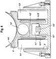
- Fig. 4 shows a drive device equipped with two linear motors is. 4, which correspond to corresponding components from FIG. 3, are identified by the same reference number and an apostrophe.
- the slide 4 ' is via a linear guide 4.1' in a central guide rail 4.3 'out.
- the primary parts 5.1 'and 5.2'der Linear motors are fixed on both sides of the slide 4 'in the carrier 3'.
- the primary parts 5.1 'and 5.2' are opposite to the two Sides of the slide, which are designed as outward-pointing components, Secondary parts 6.1 'and 6.2' made of ferromagnetic material arranged, each carrying a magnetic track 6.1 'or 6.1 ".
- Primary and Secondaries are here in the vertical direction and opposite each other aligned. With this arrangement, the tightening forces compensate each other by arranging the primary and secondary parts in pairs. However, you are still present within the structure of the carriage 4 'so that a very rigid sled structure must be realized. It also arises due to the arrangement in pairs a somewhat increased construction effort.
- the slide length can be shortened to the length of the secondary part be, which results in a weight reduction.
- the charging cradle 4.4 or 4.4 'arranged on the slide 4 or 4' can be achieved that the front end of the charging cradle when braking of the carriage into the cargo space of the weapon (Fig. 2 dashed Presentation). Through this measure, the exit behavior of the floor G noticeably at the moment of the "departure" from the attachment slide 4 improved.
- An electrical supply device for those shown in FIGS. 1 to 4 Fig. 5 shows the drive devices of the projectile attachment.
- the supply device owns one, for example, of the combat vehicle's electrical system connected battery buffer 9.
- battery buffer 9 For as synchronous machines trained linear motors must the existing DC voltage on the for the operation of the linear motor or the linear motors required AC voltage be reshaped. This is done by means of a to the battery buffer 9 connected inverters 8.
- the converter 8 contains high electrical power a short-term memory 8.1, the capacity of which is designed for a preparation process is.
- An electrical measuring system 10 attached to the attachment slide 4 or 4 ′ monitors the course of the preparation process and controls it via a control system 11 targeted the delivery of electrical power from the short-term storage 8.1 to the primary part 5 of the linear motor.
- the regulation can be carried out according to any predefinable control characteristic which the sled accelerates in the various movement phases or is slowed down.
- FIG. 6 shows the path-time profile of the attachment slide in an exemplary manner during the application process with an acceleration phase, a braking phase, a rest phase and a rewind phase.
Landscapes
- Engineering & Computer Science (AREA)
- General Engineering & Computer Science (AREA)
- Linear Motors (AREA)
- Connection Of Motors, Electrical Generators, Mechanical Devices, And The Like (AREA)
- Pharmaceuticals Containing Other Organic And Inorganic Compounds (AREA)
- Manufacturing Of Micro-Capsules (AREA)
- Hard Magnetic Materials (AREA)
- Electric Propulsion And Braking For Vehicles (AREA)
- Aiming, Guidance, Guns With A Light Source, Armor, Camouflage, And Targets (AREA)
- Toys (AREA)
- Motorcycle And Bicycle Frame (AREA)
- Control Of Electric Motors In General (AREA)
Abstract
Description
Claims (14)
- Geschoßansetzer für Artillerie mit einem hinter dem Geschütz angeordneten Schlitten, der eine fluchtend zum Ladungsraum angeordnete Aufnahmemulde mit einem Angriffselement am hinteren Ende für das Geschoß trägt und über eine Führung bewegbar auf einer parallel zur Geschützrohrachse verlaufenden Führungsbahn geführt ist und der mit einer Antriebsvorrichtung zur Beschleunigung in Richtung auf das Geschützrohr gekoppelt ist, wobei Mittel zur Abbremsung des Schlittens in einem vorgegebenen Abstand vor dem hinteren Ende des Geschützrohres vorgesehen sind, dadurch gekennzeichnet, daß die Antriebsvorrichtung mit mindestens einem elektrischen Linearmotor (5-6, 5.1'-6.1', 5.2'-6.2') ausgerüstet ist.
- Geschoßansetzer nach Anspruch 1, dadurch gekennzeichnet, daß der Primärteil (5, 5.1', 5.2") des Linearmotors, an dem die Stromzuführung erfolgt, fest mit der Führungsbahn (4.3, 4.3') verbunden ist, während der Sekundärteil (6, 6.1', 6.2') mit dem Schlitten (4, 4') verbunden ist.
- Geschoßansetzer nach Anspruch 2, dadurch gekennzeichnet, daß der Primärteil (5) des Linearmotors eine vorgegebene größere Länge besitzt als der Sekundärteil (6).
- Geschoßansetzer nach einem der Ansprüche 1 bis 3, dadurch gekennzeichnet, daß der Sekundärteil (6, 6.1', 6.2') des Linearmotors aus einem länglichen, flachen Bauelement aus ferromagnetischem Material mit einer Magnetspur (6.1, 6.11', 6.1") besteht.
- Geschoßansetzer nach einem der Ansprüche 1 bis 4, dadurch gekennzeichnet, daß die Stromversorgungseinrichtung für den Linearmotor einen elektrischen Kurzzeitspeicher (8.1) aufweist.
- Geschoßansetzer nach Anspruch 5, dadurch gekennzeichnet, daß beim Einsatz des Geschoßansetzers in einem Kampffahrzeug die Stromversorgungseinrichtung für den Linearmotor einen an das Bordnetz angeschlossenen Batteriepuffer (9) aufweist.
- Geschoßansetzer nach einem der Ansprüche 5 oder 6, dadurch gekennzeichnet, daß bei einem als Synchronmotor ausgebildeten Linearmotor die Stromversorgungseinrichtung einen Wechselrichter (8) enthält.
- Geschoßansetzer nach einem der Ansprüche 1 bis 7 gekennzeichnet durch eine elektrische Steuereinrichtung (11), durch welche der Bewegungsablauf am Linearmotor in Abhängigkeit von der zurückgelegten Wegstrecke und/oder der Bewegungsrichtung und/oder der Elevation des Geschützrohres gemäß vorgegebenen Werten steuerbar ist.
- Geschoßansetzer nach Anspruch 8, dadurch gekennzeichnet, daß die Steuereinrichtung (11) mit Meßgeräten (10) für die zurückgelegte Wegstrecke und/oder die Bewegungsrichtung und/oder die Elevation des Geschützrohres verbunden ist.
- Geschoßansetzer nach Anspruch 8 oder 9, dadurch gekennzeichnet, daß die Abbremsung der Schlittenbewegung mindestens zum Teil durch generatorische Bremsung mittels des Linearmotors erfolgt.
- Geschoßansetzer nach einem der Ansprüche 1 bis 10, dadurch gekennzeichnet, daß Primärteil (5, 5.1', 5.2') und Sekundärteil (6, 6.1', 6.2') des Linearmotors so angeordnet sind, daß der Sekundärteil nach einer vorgegebenen Wegstrecke den Einwirkungsbereich des Primärteils verläßt.
- Geschoßansetzer nach einem der Ansprüche 1 bis 11, dadurch gekennzeichnet, daß zwischen den Schlitten (4) und das hintere Ende des Geschützrohres (1) eine als Stoßdämpfer (7) ausgebildete Bremsvorrichtung eingeschaltet ist.
- Geschoßansetzer nach einem der Ansprüche 1 bis 12, dadurch gekennzeichnet, daß die Antriebsvorrichtung einen Linearmotor aufweist, dessen Primärteil (5) flach und nach oben weisend unterhalb des Schlittens (4) fest angeordnet ist, während an der Unterseite des Schlittens (4) der als längliches flaches Bauelement ausgebildete Sekundärteil (6) befestigt ist.
- Geschoßansetzer nach einem der Ansprüche 1 bis 12, dadurch gekennzeichnet, daß die Antriebsvorrichtung zwei Linearmotoren aufweist, deren Primärteile (5.1', 5.2') zu beiden Seiten des Schlittens (4') fest angeordnet sind, während an den Seiten des Schlittens (4') jeweils die als nach außen weisende Bauelemente ausgebildeten Sekundärteile (6.1', 6.2') befestigt sind.
Applications Claiming Priority (2)
| Application Number | Priority Date | Filing Date | Title |
|---|---|---|---|
| DE19955234 | 1999-11-17 | ||
| DE19955234A DE19955234A1 (de) | 1999-11-17 | 1999-11-17 | Geschoßansetzer für Artillerie |
Publications (3)
| Publication Number | Publication Date |
|---|---|
| EP1102023A2 true EP1102023A2 (de) | 2001-05-23 |
| EP1102023A3 EP1102023A3 (de) | 2002-02-06 |
| EP1102023B1 EP1102023B1 (de) | 2005-11-16 |
Family
ID=7929307
Family Applications (1)
| Application Number | Title | Priority Date | Filing Date |
|---|---|---|---|
| EP00123207A Expired - Lifetime EP1102023B1 (de) | 1999-11-17 | 2000-10-26 | Geschossansetzer für Artillerie |
Country Status (6)
| Country | Link |
|---|---|
| US (1) | US6467389B1 (de) |
| EP (1) | EP1102023B1 (de) |
| AT (1) | ATE310223T1 (de) |
| DE (2) | DE19955234A1 (de) |
| ES (1) | ES2251340T3 (de) |
| PL (1) | PL193246B1 (de) |
Cited By (2)
| Publication number | Priority date | Publication date | Assignee | Title |
|---|---|---|---|---|
| CN103776296A (zh) * | 2014-01-17 | 2014-05-07 | 中国船舶重工集团公司第七一〇研究所 | 多功能手动装退弹推杆 |
| FR3123977A1 (fr) * | 2021-06-15 | 2022-12-16 | Nexter Systems | Dispositif de mise a poste d'un projectile |
Families Citing this family (5)
| Publication number | Priority date | Publication date | Assignee | Title |
|---|---|---|---|---|
| EP1639309A1 (de) * | 2003-07-02 | 2006-03-29 | Denel (Pty) Ltd | Munitionszufuhrvorrichtung |
| FR2945616B1 (fr) * | 2009-05-13 | 2011-07-29 | Nexter Systems | Dispositif de chargement d'une munition |
| DE102014017554B4 (de) * | 2014-11-28 | 2021-12-23 | Thyssenkrupp Ag | Vorrichtung zum Ausstoßen eines Objekts aus einem Waffenrohr mit einem Linearmotor |
| DE102019203071B4 (de) * | 2019-03-06 | 2022-04-28 | Thyssenkrupp Ag | Brückenlose Waffenmulde |
| DE102019211285B3 (de) * | 2019-07-30 | 2020-09-24 | Thyssenkrupp Ag | Waffenbrücke |
Citations (2)
| Publication number | Priority date | Publication date | Assignee | Title |
|---|---|---|---|---|
| CH664627A5 (de) | 1986-11-20 | 1988-03-15 | Sig Schweiz Industrieges | Beschleunigungseinrichtung fuer eine ladevorrichtung eines geschuetzes. |
| EP0352584A2 (de) | 1988-07-28 | 1990-01-31 | Wegmann & Co. GmbH | Geschossansetzer für Artillerie |
Family Cites Families (8)
| Publication number | Priority date | Publication date | Assignee | Title |
|---|---|---|---|---|
| FR1595414A (de) * | 1968-12-19 | 1970-06-08 | ||
| DE2455994C3 (de) * | 1974-11-27 | 1980-01-10 | Mak Maschinenbau Gmbh, 2300 Kiel | Vorrichtung zum Ausstoßen bzw. Ablaufen von Tauch- und Schwimmkörpern aus Rohren |
| DE2460507C3 (de) * | 1974-12-20 | 1979-12-06 | Walter 6600 Saarbruecken Landsrath | Schießgerät für in einem Rohr zu beschleunigende Geschosse |
| DE3208941C2 (de) * | 1982-03-12 | 1985-10-10 | Rheinmetall GmbH, 4000 Düsseldorf | Vorrichtung zum Übertragen von Energie auf den Verschlußkörper eines Geradzugverschlusses einer automatischen Rohrwaffe |
| US4555972A (en) * | 1982-12-20 | 1985-12-03 | Westinghouse Electric Corp. | Electromagnetic launcher with powder driven projectile insertion |
| US4791850A (en) * | 1986-01-23 | 1988-12-20 | Minovitch Michael Andrew | Electromagnetic launching system for long-range guided munitions |
| DE3644513C1 (de) * | 1986-12-24 | 1992-08-27 | Dornier Gmbh | Munitionszufuehrung |
| DE3940421A1 (de) * | 1989-12-07 | 1991-06-13 | Wegmann & Co | Vorrichtung zur zufuehrung von treibladungen fuer rohrwaffen groesseren kalibers |
-
1999
- 1999-11-17 DE DE19955234A patent/DE19955234A1/de not_active Withdrawn
-
2000
- 2000-10-26 EP EP00123207A patent/EP1102023B1/de not_active Expired - Lifetime
- 2000-10-26 DE DE50011622T patent/DE50011622D1/de not_active Expired - Lifetime
- 2000-10-26 AT AT00123207T patent/ATE310223T1/de active
- 2000-10-26 ES ES00123207T patent/ES2251340T3/es not_active Expired - Lifetime
- 2000-11-08 US US09/708,144 patent/US6467389B1/en not_active Expired - Fee Related
- 2000-11-15 PL PL343880A patent/PL193246B1/pl unknown
Patent Citations (2)
| Publication number | Priority date | Publication date | Assignee | Title |
|---|---|---|---|---|
| CH664627A5 (de) | 1986-11-20 | 1988-03-15 | Sig Schweiz Industrieges | Beschleunigungseinrichtung fuer eine ladevorrichtung eines geschuetzes. |
| EP0352584A2 (de) | 1988-07-28 | 1990-01-31 | Wegmann & Co. GmbH | Geschossansetzer für Artillerie |
Cited By (4)
| Publication number | Priority date | Publication date | Assignee | Title |
|---|---|---|---|---|
| CN103776296A (zh) * | 2014-01-17 | 2014-05-07 | 中国船舶重工集团公司第七一〇研究所 | 多功能手动装退弹推杆 |
| CN103776296B (zh) * | 2014-01-17 | 2015-06-10 | 中国船舶重工集团公司第七一〇研究所 | 多功能手动装退弹推杆 |
| FR3123977A1 (fr) * | 2021-06-15 | 2022-12-16 | Nexter Systems | Dispositif de mise a poste d'un projectile |
| EP4105591A1 (de) * | 2021-06-15 | 2022-12-21 | NEXTER Systems | Vorrichtung zur positionierung eines geschosses |
Also Published As
| Publication number | Publication date |
|---|---|
| US6467389B1 (en) | 2002-10-22 |
| EP1102023A3 (de) | 2002-02-06 |
| ATE310223T1 (de) | 2005-12-15 |
| PL343880A1 (en) | 2001-05-21 |
| EP1102023B1 (de) | 2005-11-16 |
| ES2251340T3 (es) | 2006-05-01 |
| DE50011622D1 (de) | 2005-12-22 |
| DE19955234A1 (de) | 2001-05-23 |
| PL193246B1 (pl) | 2007-01-31 |
Similar Documents
| Publication | Publication Date | Title |
|---|---|---|
| EP3119636B1 (de) | Stromabnehmersystem mit teleskoparm für krane, containerkrane, ertgs und fördereinrichtungen | |
| EP2281742B1 (de) | Lager- und Beschickungseinrichtung für eine Waffe in einem Unterseeboot | |
| EP2195186B1 (de) | Magnetschwebefahrzeug und verfahren zum anheben und/oder absetzen desselben | |
| DE2331607A1 (de) | Vorrichtung zur halterung einer ladung | |
| EP3169966B1 (de) | Waffentransportsystem für ein unterseeboot | |
| DE102009057014A1 (de) | Vorrichtung zum Schließen einer absenkbaren Schütte eines Gepäckfachs | |
| EP2282939B1 (de) | Katapult zum abschiessen eines fluggeräts | |
| EP1102023A2 (de) | Geschossansetzer für Artillerie | |
| DE4328461A1 (de) | Verfahren und Anordnung zum Fördern flächiger Werkstücke | |
| DE3147784C2 (de) | Fördervorrichtung für eine Transferstraße | |
| DE1904053B2 (de) | Stossfaenger fuer kraftfahrzeuge | |
| EP1830153B1 (de) | Treibladungszuführungssystem | |
| DE60025506T2 (de) | Verfahren und vorrichtung zum laden einer artilleriekanone mit einem automatischen ansetzer | |
| EP2794138B1 (de) | Eintreibvorrichtung | |
| DE102015000601A1 (de) | Vorrichtung zum Umschlag von Bauteilen | |
| DE3208942C2 (de) | Maschinenkanone mit zwei zum Vor- und Rücklauf nebeneinander in einem Waffengehäuse angeordneten Waffenrohren | |
| EP1043561B1 (de) | Waffensimulator für ein Kampffahrzeug, insbesondere einen Kampfpanzer | |
| DE3208941C2 (de) | Vorrichtung zum Übertragen von Energie auf den Verschlußkörper eines Geradzugverschlusses einer automatischen Rohrwaffe | |
| DE1264296B (de) | Ladevorrichtung fuer Waffen, wie Maschinengewehre und Kanonen | |
| WO2010108510A1 (de) | Linearachsenantrieb, insbesondere für werkzeugmaschinen | |
| DE19622768A1 (de) | Bedienergeführtes Handhabungsgerät | |
| DE102021129050B3 (de) | Achsvorrichtung mit Energiespeicheranordnung sowie Förderanlage mit der Achsvorrichtung | |
| DE2064733A1 (de) | Koksofenbedienungsmaschine | |
| DE1456404B2 (de) | Betaetigungsvorrichtung fuer eine aufzugs schiebetuer | |
| DD148868A3 (de) | Pressenstrasse |
Legal Events
| Date | Code | Title | Description |
|---|---|---|---|
| PUAI | Public reference made under article 153(3) epc to a published international application that has entered the european phase |
Free format text: ORIGINAL CODE: 0009012 |
|
| AK | Designated contracting states |
Kind code of ref document: A2 Designated state(s): AT BE CH CY DE DK ES FI FR GB GR IE IT LI LU MC NL PT SE |
|
| AX | Request for extension of the european patent |
Free format text: AL;LT;LV;MK;RO;SI |
|
| PUAL | Search report despatched |
Free format text: ORIGINAL CODE: 0009013 |
|
| AK | Designated contracting states |
Kind code of ref document: A3 Designated state(s): AT BE CH CY DE DK ES FI FR GB GR IE IT LI LU MC NL PT SE |
|
| AX | Request for extension of the european patent |
Free format text: AL;LT;LV;MK;RO;SI |
|
| 17P | Request for examination filed |
Effective date: 20020315 |
|
| AKX | Designation fees paid |
Free format text: AT BE CH CY DE DK ES FI FR GB GR IE IT LI LU MC NL PT SE |
|
| 17Q | First examination report despatched |
Effective date: 20030918 |
|
| GRAP | Despatch of communication of intention to grant a patent |
Free format text: ORIGINAL CODE: EPIDOSNIGR1 |
|
| GRAS | Grant fee paid |
Free format text: ORIGINAL CODE: EPIDOSNIGR3 |
|
| GRAA | (expected) grant |
Free format text: ORIGINAL CODE: 0009210 |
|
| AK | Designated contracting states |
Kind code of ref document: B1 Designated state(s): AT BE CH CY DE DK ES FI FR GB GR IE IT LI LU MC NL PT SE |
|
| PG25 | Lapsed in a contracting state [announced via postgrant information from national office to epo] |
Ref country code: IE Free format text: LAPSE BECAUSE OF FAILURE TO SUBMIT A TRANSLATION OF THE DESCRIPTION OR TO PAY THE FEE WITHIN THE PRESCRIBED TIME-LIMIT Effective date: 20051116 Ref country code: FI Free format text: LAPSE BECAUSE OF FAILURE TO SUBMIT A TRANSLATION OF THE DESCRIPTION OR TO PAY THE FEE WITHIN THE PRESCRIBED TIME-LIMIT Effective date: 20051116 |
|
| REG | Reference to a national code |
Ref country code: GB Ref legal event code: FG4D Free format text: NOT ENGLISH |
|
| REG | Reference to a national code |
Ref country code: CH Ref legal event code: EP |
|
| REG | Reference to a national code |
Ref country code: IE Ref legal event code: FG4D Free format text: LANGUAGE OF EP DOCUMENT: GERMAN |
|
| REF | Corresponds to: |
Ref document number: 50011622 Country of ref document: DE Date of ref document: 20051222 Kind code of ref document: P |
|
| GBT | Gb: translation of ep patent filed (gb section 77(6)(a)/1977) |
Effective date: 20051205 |
|
| REG | Reference to a national code |
Ref country code: CH Ref legal event code: NV Representative=s name: A. BRAUN, BRAUN, HERITIER, ESCHMANN AG PATENTANWAE |
|
| PG25 | Lapsed in a contracting state [announced via postgrant information from national office to epo] |
Ref country code: DK Free format text: LAPSE BECAUSE OF FAILURE TO SUBMIT A TRANSLATION OF THE DESCRIPTION OR TO PAY THE FEE WITHIN THE PRESCRIBED TIME-LIMIT Effective date: 20060216 |
|
| REG | Reference to a national code |
Ref country code: SE Ref legal event code: TRGR |
|
| REG | Reference to a national code |
Ref country code: GR Ref legal event code: EP Ref document number: 20050403955 Country of ref document: GR |
|
| PG25 | Lapsed in a contracting state [announced via postgrant information from national office to epo] |
Ref country code: PT Free format text: LAPSE BECAUSE OF FAILURE TO SUBMIT A TRANSLATION OF THE DESCRIPTION OR TO PAY THE FEE WITHIN THE PRESCRIBED TIME-LIMIT Effective date: 20060417 |
|
| REG | Reference to a national code |
Ref country code: ES Ref legal event code: FG2A Ref document number: 2251340 Country of ref document: ES Kind code of ref document: T3 |
|
| ET | Fr: translation filed | ||
| REG | Reference to a national code |
Ref country code: IE Ref legal event code: FD4D |
|
| PLBE | No opposition filed within time limit |
Free format text: ORIGINAL CODE: 0009261 |
|
| STAA | Information on the status of an ep patent application or granted ep patent |
Free format text: STATUS: NO OPPOSITION FILED WITHIN TIME LIMIT |
|
| 26N | No opposition filed |
Effective date: 20060817 |
|
| PG25 | Lapsed in a contracting state [announced via postgrant information from national office to epo] |
Ref country code: MC Free format text: LAPSE BECAUSE OF NON-PAYMENT OF DUE FEES Effective date: 20061031 |
|
| BERE | Be: lapsed |
Owner name: KRAUSS-MAFFEI WEGMANN G.M.B.H. & CO. KG Effective date: 20061031 |
|
| REG | Reference to a national code |
Ref country code: CH Ref legal event code: PFA Owner name: KRAUSS-MAFFEI WEGMANN GMBH & CO. KG Free format text: KRAUSS-MAFFEI WEGMANN GMBH & CO. KG#AUGUST-BODE-STRASSE 1#34127 KASSEL (DE) -TRANSFER TO- KRAUSS-MAFFEI WEGMANN GMBH & CO. KG#AUGUST-BODE-STRASSE 1#34127 KASSEL (DE) |
|
| PG25 | Lapsed in a contracting state [announced via postgrant information from national office to epo] |
Ref country code: LU Free format text: LAPSE BECAUSE OF NON-PAYMENT OF DUE FEES Effective date: 20061026 |
|
| PG25 | Lapsed in a contracting state [announced via postgrant information from national office to epo] |
Ref country code: CY Free format text: LAPSE BECAUSE OF FAILURE TO SUBMIT A TRANSLATION OF THE DESCRIPTION OR TO PAY THE FEE WITHIN THE PRESCRIBED TIME-LIMIT Effective date: 20051116 |
|
| PG25 | Lapsed in a contracting state [announced via postgrant information from national office to epo] |
Ref country code: BE Free format text: LAPSE BECAUSE OF FAILURE TO SUBMIT A TRANSLATION OF THE DESCRIPTION OR TO PAY THE FEE WITHIN THE PRESCRIBED TIME-LIMIT Effective date: 20061031 |
|
| PGFP | Annual fee paid to national office [announced via postgrant information from national office to epo] |
Ref country code: GR Payment date: 20121029 Year of fee payment: 13 Ref country code: IT Payment date: 20121026 Year of fee payment: 13 Ref country code: SE Payment date: 20121024 Year of fee payment: 13 Ref country code: ES Payment date: 20121023 Year of fee payment: 13 |
|
| REG | Reference to a national code |
Ref country code: SE Ref legal event code: EUG |
|
| REG | Reference to a national code |
Ref country code: GR Ref legal event code: ML Ref document number: 20050403955 Country of ref document: GR Effective date: 20140505 |
|
| REG | Reference to a national code |
Ref country code: CH Ref legal event code: PCAR Free format text: NEW ADDRESS: HOLBEINSTRASSE 36-38, 4051 BASEL (CH) |
|
| PG25 | Lapsed in a contracting state [announced via postgrant information from national office to epo] |
Ref country code: GR Free format text: LAPSE BECAUSE OF NON-PAYMENT OF DUE FEES Effective date: 20140505 Ref country code: SE Free format text: LAPSE BECAUSE OF NON-PAYMENT OF DUE FEES Effective date: 20131027 Ref country code: IT Free format text: LAPSE BECAUSE OF NON-PAYMENT OF DUE FEES Effective date: 20131026 |
|
| REG | Reference to a national code |
Ref country code: ES Ref legal event code: FD2A Effective date: 20141107 |
|
| PG25 | Lapsed in a contracting state [announced via postgrant information from national office to epo] |
Ref country code: ES Free format text: LAPSE BECAUSE OF NON-PAYMENT OF DUE FEES Effective date: 20131027 |
|
| REG | Reference to a national code |
Ref country code: FR Ref legal event code: PLFP Year of fee payment: 16 |
|
| REG | Reference to a national code |
Ref country code: FR Ref legal event code: PLFP Year of fee payment: 17 |
|
| PGFP | Annual fee paid to national office [announced via postgrant information from national office to epo] |
Ref country code: FR Payment date: 20161025 Year of fee payment: 17 Ref country code: DE Payment date: 20161031 Year of fee payment: 17 Ref country code: GB Payment date: 20161025 Year of fee payment: 17 Ref country code: CH Payment date: 20161025 Year of fee payment: 17 Ref country code: NL Payment date: 20161025 Year of fee payment: 17 |
|
| PGFP | Annual fee paid to national office [announced via postgrant information from national office to epo] |
Ref country code: AT Payment date: 20161024 Year of fee payment: 17 |
|
| REG | Reference to a national code |
Ref country code: DE Ref legal event code: R119 Ref document number: 50011622 Country of ref document: DE |
|
| REG | Reference to a national code |
Ref country code: CH Ref legal event code: PL |
|
| REG | Reference to a national code |
Ref country code: NL Ref legal event code: MM Effective date: 20171101 |
|
| REG | Reference to a national code |
Ref country code: AT Ref legal event code: MM01 Ref document number: 310223 Country of ref document: AT Kind code of ref document: T Effective date: 20171026 |
|
| GBPC | Gb: european patent ceased through non-payment of renewal fee |
Effective date: 20171026 |
|
| REG | Reference to a national code |
Ref country code: FR Ref legal event code: ST Effective date: 20180629 |
|
| PG25 | Lapsed in a contracting state [announced via postgrant information from national office to epo] |
Ref country code: NL Free format text: LAPSE BECAUSE OF NON-PAYMENT OF DUE FEES Effective date: 20171101 Ref country code: DE Free format text: LAPSE BECAUSE OF NON-PAYMENT OF DUE FEES Effective date: 20180501 Ref country code: GB Free format text: LAPSE BECAUSE OF NON-PAYMENT OF DUE FEES Effective date: 20171026 Ref country code: LI Free format text: LAPSE BECAUSE OF NON-PAYMENT OF DUE FEES Effective date: 20171031 Ref country code: CH Free format text: LAPSE BECAUSE OF NON-PAYMENT OF DUE FEES Effective date: 20171031 |
|
| PG25 | Lapsed in a contracting state [announced via postgrant information from national office to epo] |
Ref country code: AT Free format text: LAPSE BECAUSE OF NON-PAYMENT OF DUE FEES Effective date: 20171026 Ref country code: FR Free format text: LAPSE BECAUSE OF NON-PAYMENT OF DUE FEES Effective date: 20171031 |