EP1097644B1 - Device for processing slaughtered animals or parts thereof - Google Patents
Device for processing slaughtered animals or parts thereof Download PDFInfo
- Publication number
- EP1097644B1 EP1097644B1 EP00203890A EP00203890A EP1097644B1 EP 1097644 B1 EP1097644 B1 EP 1097644B1 EP 00203890 A EP00203890 A EP 00203890A EP 00203890 A EP00203890 A EP 00203890A EP 1097644 B1 EP1097644 B1 EP 1097644B1
- Authority
- EP
- European Patent Office
- Prior art keywords
- slot
- parts
- slaughtered animals
- conveyor
- station
- Prior art date
- Legal status (The legal status is an assumption and is not a legal conclusion. Google has not performed a legal analysis and makes no representation as to the accuracy of the status listed.)
- Expired - Lifetime
Links
Images


Classifications
-
- A—HUMAN NECESSITIES
- A22—BUTCHERING; MEAT TREATMENT; PROCESSING POULTRY OR FISH
- A22C—PROCESSING MEAT, POULTRY, OR FISH
- A22C21/00—Processing poultry
- A22C21/0053—Transferring or conveying devices for poultry
Definitions
- the invention relates to a device for processing slaughtered animals or parts thereof, having a first station and a second station, comprising a conveyor which extends between the first station and the second station and which comprises at least one slot with a width and a course, supply means for supplying the slaughtered animals or parts thereof at the first station to the conveyor, discharge means for discharging the slaughtered animals or parts thereof from the conveyor at the second station, and at least one driven driving member which passes through a path which is substantially parallel to the course of the at least one slot and is designed to move the slaughtered animals or parts thereof from the first station towards the second station, along the at least one slot, wherein the at least one driving member spans at least half the width of the at least one slot.
- a device for transferring product carriers which travel or slide along a first conveyor track, via a connecting conveyor track, to a second conveyor track.
- the product carriers are removed from the first conveyor track with the aid of a switching mechanism.
- the product carriers are moved along the connecting conveyor track by means of arms which are mounted on a rotatably driven disc, are spring-mounted and describe a circular path which is in part parallel to a section of the course of the connecting conveyor track.
- the arms bear against the product carriers and, in doing so, exert a force on the product carriers which makes the product carriers advance along the connecting conveyor track.
- a drawback of the device which is known from FR-A-1 408 850 is that it is not possible for the products which are conveyed by the product carriers, to be transferred from the first conveyor track to the second conveyor track separately from the product carriers.
- a second drawback is that the product carriers to be transferred cannot be temporarily stored and cannot be controllably discharged to the second conveyor track, making the device unsuitable for the selective processing of slaughtered animals or parts thereof.
- the object of the invention is to provide a device of the above-mentioned type which at least partially overcomes the abovementioned drawbacks.
- the invention is characterized by the features of claim 1.
- the slaughtered animals or parts thereof can be supplied to and discharged from the device, for example from or to a conveyor track located along the device, by either mechanical or manual means.
- the at least one driving member can adopt a first position and a second position, in which the slaughtered animals or parts thereof are and are not, respectively, moved from the first station towards the second station.
- the latter will be able to move past the slaughtered animals or parts thereof situated in the at least one slot scarcely without damaging the slaughtered animals or parts thereof.
- the at least one driving member can rotate about an axis which is substantially perpendicular to the path covered by the at least one driving member, so that it is easy to carry out a movement from the first position towards the second position and vice versa.
- the at least one driving member comprises at least one arm which is designed to transmit the movement of the at least one driving member to the slaughtered animals or parts thereof, so that a simple structure of great durability is obtained.
- the at least one driving member is provided with force means which oppose a movement of the at least one driving member from the first position towards the second position, specifically in such a manner that the movement from the first position towards the second position takes place in a controlled way.
- force means which oppose a movement of the at least one driving member from the first position towards the second position, specifically in such a manner that the movement from the first position towards the second position takes place in a controlled way.
- the force means comprise separate spring means, such as compression springs, tension springs or torsion springs, although the force means may also be formed by the at least one driving member itself being flexible and resilient.
- the force means advantageously comprise a controllable piston-cylinder device, so that it is possible to actively adjust the position of the at least one driving member.
- the piston-cylinder device can make the at least one driving member adopt any desired position between the first position and the second position, so that it is possible to set the most favourable position of the at least one driving member with respect to the slaughtered animals or parts thereof which are to be transported.
- the at least one driving member is also provided with a resilient effect which is dependent on the pressure prevailing in the piston-cylinder device.
- driving members which do not span at least half the width of the slot but are formed, for example, by the driven conveyor belts as described in NL-A-7412044.
- either the supply means are designed to selectively supply the slaughtered animals or parts thereof to the at least one slot and/or the discharge means are designed to selectively discharge the slaughtered animals or parts thereof from the at least one slot.
- the device can be used to selectively transfer the slaughtered animals from the first station to the second station.
- the supply means comprise a switching mechanism.
- the switching mechanism may be put into a first switched position, in which the slaughtered animals or parts thereof are supplied to the at least one slot of the conveyor, and into a second switched position, in which the slaughtered animals or parts thereof are not supplied to the at least one slot of the conveyor. If it is assumed that the device interacts with a conveyor in which slaughtered animals or parts thereof are conveyed at or on carrying means past the first station, the slaughtered animals or parts thereof can be selectively supplied to the at least one slot of the conveyor.
- the switching mechanism preferably comprises a switching plate which, in a first position, guides the slaughtered animals or parts thereof towards the at least one slot of the conveyor. In this way, it is possible for the structure and action of the switching mechanism to be of simple design.
- supply-control means and/or discharge-control means are provided, which control the supply and discharge means, respectively, the control being effected on the basis of data relating to the slaughtered animals or parts thereof to be transferred, such as size, weight, contours, colour, abnormalities and the like.
- Providing the device with supply-control means enables the slaughtered animals to be transferred selectively from a conveyor to the device according to the invention on the basis of the said information relating to the slaughtered animals, such as size, weight, contours, colour, abnormalities and the like, so that the slaughtered animals or parts thereof can be selectively transferred from the first station to the second.
- Providing the device according to the invention with discharge-control means enables the slaughtered animals to be discharged selectively in a corresponding way.
- the supply means and/or the discharge means comprise at least one rotatably driven disc which on its circumference is provided with at least one holding slot, which opens out on the outer circumference of the at least one rotatably driven disc and is designed to carry and support in it at least one slaughtered animal or a part thereof.
- a disc of this nature is easy and inexpensive to produce and can be cleaned successfully.
- the slaughtered animals or parts thereof can be moved one by one out of the at least one slot in the conveyor into a holding slot in the at least one disc by the at least one rotatably driven disc and, from this holding slot, can be placed into a part of the slot in which the slaughtered animals or parts thereof can be temporarily stored.
- the at least one rotatably driven disc has at least two holding slots, so that when a slaughtered animal is moved from an occupied holding slot into a part of the slot, the other holding slot is already available for holding a slaughtered animal from the at least one slot of the conveyor, so that it is possible to achieve a high speed of transfer of the slaughtered animals.
- the slaughtered animals or parts thereof may, for example, be selectively supplied to the at least one slot at the first station or may be selectively discharged from the at least one slot at the second station, or both.
- the at least one slot of the conveyor extends substantially in a horizontal plane, so that the slaughtered animals or parts thereof cannot move undesirably within this slot under the influence of the force of gravity.
- the at least one slot of the device according to the invention prefferably has a substantially curved course. This enables a support of the driving members to be designed simply so as to rotate about an axis.
- the at least one slot will be able to tangentially adjoin the conveyor track by means of a suitably curved course in the vicinity of the first and/or second station, so that it is very easy to supply or discharge the slaughtered animals or parts thereof to or from the at least one slot.
- the at least one slot has a substantially straight course.
- an unloading device is provided inside the slot, which device is preferably designed to locally widen the at least one slot. This makes it possible to remove the slaughtered animals or parts thereof from the slot between the first station and the second station while they are being transferred.
- the unloading device comprises a support member which defines a section of the at least one slot and can move substantially transversely with respect to the direction of the slot, in order to locally increase the width of the slot, so that at that location the width of the at least one slot can be increased in such a manner that the slaughtered animals or parts thereof are no longer supported and will fall out of the at least one slot.
- the device according to the invention preferably comprises unloading-control means for controlling the unloading device, for example on the basis of previously recorded data.
- a weighing device is incorporated in the at least one slot for weighing the slaughtered animals or parts thereof. This makes it possible to determine the weight of the slaughtered animals or parts thereof which are situated in the at least one slot, on the basis of which it is possible to select further processing operations to be carried out on the slaughtered animals or parts thereof.
- the unloading-control means record the weight of the slaughtered animals or parts thereof which has been detected by the weighing device and control the unloading device on the basis of this data, for example its support member, so that it becomes possible to selectively remove the slaughtered animals or parts thereof from the at least one slot between the first station and the second station.
- a processing device is provided along the course of the at least one slot, for processing the slaughtered animals or parts thereof.
- the advantage which ensues is that the slaughtered animals or parts thereof are already undergoing a processing step while they are being conveyed in the at least one slot, so that it is possible to dispense with a processing station of this type further on in the line. This saves space. In this way, it is also possible to make good use of the time which the slaughtered animals or parts thereof spend in the slot, in particular if they are temporarily stored therein, for a processing step to be carried out, so that time is saved in an overall processing sequence.
- the processing device comprises at least one frictional surface which is arranged along the at least one slot and is designed to act on part of the slaughtered animals or parts thereof.
- This enables the slaughtered animals or parts thereof, in particular the legs, to rotate at the location of the processing device, with the result that the slaughtered animals or parts thereof animals, in particular the legs, can, for example, be marinated with ease.
- the frictional surface it is preferable for the frictional surface to form part of a driven conveyor belt, a section of which extends along at least a section of the slot.
- the processing device comprises two driven conveyor belts which are arranged on either side of the at least one slot, for clamping a part of the slaughtered animals or parts thereof between them, with the result that they can be handled particularly well.
- the processing device comprises at least two driven conveyor belts which are arranged one behind the other along the at least one slot.
- the direction and/or speed of movement of a first conveyor belt differs from that of a second conveyor belt, so that there is considerable freedom available for moving the slaughtered animals or parts thereof into a desired position with respect to one another (for example at a distance from one another along the slot) and into a desired position for themselves.
- the processing device described above can be used not only as a component of the device according to the invention but also on its own.
- Figure 1 diagrammatically shows a first conveyor 1 and a second conveyor 2, along which product carriers 3 are advanced in a direction indicated by arrow 4 and arrow 5. Slaughtered animals or parts thereof, in particular legs 6 of poultry, are situated in the product carriers 3. The legs 6 can be selectively transferred from the first conveyor 1 to the second conveyor 2 with the aid of the conveyor device, which is denoted overall by reference numeral 7.
- the conveyor device 7 comprises a support 8 in the form of a disc, which is mounted in a frame (not shown) in such a manner that it can rotate about an axis 9.
- the legs 6 may be supplied to the slot 12 via a supply end thereof and can be discharged therefrom via a discharge end of the slot.
- the conveyor device 7 comprises a switching mechanism with a substantially triangular switching plate 13.
- the switching plate 13 is pivotably connected to a frame (not shown).
- the switching plate 13 can adopt various positions, namely a first position 13a, which is indicated by a solid line, and a second position 13b, which is indicated by a dashed line.
- the conveyor device 7 comprises a discharge means 14.
- the discharge means 14 comprises a rotatably driven disc 15 and a stationary waiting slot 16, in which the legs 6 can be temporarily stored.
- the disc 15 On its outer circumference, the disc 15 is provided with two holding slots 17 which are located diametrically opposite one another and are designed to carry and support one leg 6 each, and on its outer circumference, next to the holding slot 17, the disc has two diametrically opposite projections 18.
- the driving members 10 comprise an arm 19 having a first, free end 20 and a second, substantially T-shaped end 21. At the T-shaped end 21, the arm 19 is pivotably coupled to the support 8 via the pivot 11.
- the T-shaped end 21 comprises two projections 22, 23 which run substantially transversely with respect to the arm 19.
- the projection 22 is coupled, via a pivot 24, to a compression spring 26 which is fixedly connected to the support 8 by a connection means 25.
- the conveyor device 7 comprises supply-control means 42 for controlling the position of the switching plate 13 and discharge-control means 52 for controlling the angular position of the rotatably driven disc 15.
- the position of the switching mechanism with switching plate 13 is controlled by the supply-control means 42, as symbolically indicated by dashed line 41, as a result of this data being compared with predetermined criteria, in order that the slaughtered animals or parts 6 thereof can be optionally transferred from the first conveyor 1 into the slot 12.
- the switching mechanism in particular the switching plate 13, is activated in such a manner by the supply-control means 42 that it adopts the position 13b and guides the selected animal or part 6 thereof out of the product carrier into the slot 12.
- data 44 detected using suitable measuring means such as the type, number, position, order or the like, or, for example, a signal from a slot-full detector (not shown in more detail) relating to the slaughtered animals or parts 6 thereof situated in the slot 12, to be fed to the supply-control means.
- suitable measuring means such as the type, number, position, order or the like, or, for example, a signal from a slot-full detector (not shown in more detail) relating to the slaughtered animals or parts 6 thereof situated in the slot 12, to be fed to the supply-control means.
- suitable measuring means such as the type, number, position, order or the like
- a signal from a slot-full detector not shown in more detail
- the driving members 10 arranged on the support 8 rotate in a direction which is symbolically denoted by arrow 27.
- the driving members 10, the arms 19 in particular, move substantially parallel to the path of the slot 12, just below the latter, and as they move they take a slaughtered animal or part 6 thereof with them from the first station towards the second station along the slot 12.
- the compression spring 26 connected to the projection 22 exerts a restoring force on the arm 19, tending to turn the arm 19 in the direction indicated by arrow 27.
- the arm 19 can execute a pivoting movement about the pivot 11, counter to the restoring force of the compression spring 26, the arm 19 being able to adopt a position 19b in which the arm 19 does not move the legs 6 along the slot 12. For example, if a plurality of legs 6 have collected in the slot 12 at the discharge end, the arm 19 pivots in a direction which is opposite to the direction of rotation of the support 8, so that the driving members 10, in particular the arms 19, are able to move past the legs 6 which have collected at the discharge end. This prevents the slaughtered animals or parts 6 thereof which have collected in the vicinity of the discharge end being damaged.
- the compression spring 26 will turn the arms 19 until the projection 23 is resting against a stop 28.
- slaughtered animals or parts 6 thereof situated in the slot 12 are pressed into an available holding slot 17 in the rotatably driven disc 15 by the driving members 10, the holding slot 17 being able to hold precisely one slaughtered animal or part 6 thereof.
- discharge-control means 52 control the rotatably driven disc 15, which is designed for discharging the legs 6 from the slot 12 to the waiting slot 16.
- the control of the rotatably driven disc 15 is symbolically indicated by dashed line 51 and takes place on the basis of data relating to unoccupied product supports 3, which are advanced in conveyor 2, which information is fed to the discharge-control means 52 and has been detected along the conveyor 2 upstream of the discharge slot 16, all this being diagrammatically indicated by dashed line 53.
- This control may be supplemented by control on the basis of the data relating to the legs 6 situated in the slot 12, such as the type, number, position, order and the like, as symbolically indicated by dashed line 44b.
- the discharge-control means 52 actuate the rotatably driven disc 15 in such a manner that the slaughtered animal or part 6 thereof situated in a holding slot 17 is transferred to the stationary waiting slot 16, after which the slaughtered animal or part 6 thereof is picked up by a product carrier 3 which is just moving past.
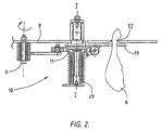
- FIG 2 shows a conveyor device according to the invention in which torsion springs 29 are used instead of the compression springs 26 shown in Figure 1.
- the torsion springs 29 extend substantially in the longitudinal direction of an axis of rotation, which is symbolically indicated by I-I.
- the torsion springs 29 are arranged on the support 8, which can rotate about the axis 9. The way in which the conveyor device according to the invention operates does not change compared to the embodiment shown in Figure 1.
- the slot 12 extends substantially in a horizontal plane and also has a course which runs substantially in the form of part of a circle.
- the slot 12 it is also conceivable for the slot 12 to have a substantially straight course or any arbitary course, in which case the driving members are moved in such a manner that they follow a corresponding path.
- the slot 12 it is also possible for the slot 12 to extend in a plane which is not horizontal, making it possible for the slaughtered animals or parts thereof to be transferred from a first conveyor to a second conveyor which is at a different height.
- Figure 3 shows a support 8a in which the driving members 10a are connected to one another and are mounted on rollers, and can be advanced along the support 8a. This is symbolically indicated by arrow 30.
- the driving members 10a are provided with spring means 31 and pivoting arms 35.
- a configuration of this nature enables the path of the driving members 10a to be adapted easily to, for example, the above-mentioned arbitrary course or variable-height course of the slot 12a.
- Figure 4 shows a support 8b in an alternative embodiment, in which it is composed of a ring with spokes and can rotate in its entirety about an axis 9a.
- the driving members 10b are provided on the circumference of the support 8b and are provided with spring means 31a similar to the spring means 31 shown in Figure 3, and pivoting arms 35a.
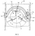
- FIG 5 diagrammatically shows a variant of the conveyor device shown in Figure 1, denoted overall by 507, the conveyor device 507 being provided with two substantially curved slots 512 which run at a distance from one another and are designed to carry and support therein the legs of slaughtered animals 506.
- the conveyor device 507 shown in Figure 5 is provided with a plurality of driving members 10 which are arranged on a rotatably driven support 8 and are pivotably connected to the support 8 via a pivot 11.
- the driving members 10 are shown in two limit positions, namely a first limit position 10a, in solid lines, and a second limit position 10b, in dashed lines. In a first limit position, the driving members 10 span the two slots 512, while in the second limit position 10b the driving members 10 do not span the two slots 512.
- Single-acting or double-acting cylinders 526 are arranged on the support 8 and are pivotably connected to the driving members 10 via an arm 60.
- a cylinder 526 By actuation of a cylinder 526, it is possible for the arm 60 to be retracted or extended. In the fully retracted position of the arm 60, a driving member 10 adopts the second limit position 10b, while in the fully extended state of the arm 60, the driving member 10 adopts the first limit position 10a.
- the cylinders 526 may also, for example, be controlled in such a manner, by control means (not shown), that the driving members 10 can adopt any desired position between the limit positions 10a, 10b.
- the conveyor device 507 interacts with a first conveyor 1, which is diagrammatically depicted, at an entry end to the slot 512, and with a second conveyor 2, which is likewise diagrammatically depicted, at a discharge end of the slots 512.
- Product carriers 3 are moved along the first conveyor 1 and along the second conveyor 2 in the direction of arrows 504 and 505, respectively.
- the product carriers 3 are designed to carry and support the slaughtered animals 506 and, at least in the vicinity of the entry end and in the vicinity of the discharge end, are at an angle, in particular at right angles, to their conveying direction.
- the slaughtered animal 506 then hangs in the slots 512 by its legs and can be conveyed via the slots 512 towards the discharge end, where the slaughtered animal 506 can be discharged to an unoccupied product support 3, which is being advanced along the second conveyor 2.
- the driving members 10 move the slaughtered animals 506 along in the direction of the arrow 27 in the known way, for which purpose the driving members 10 are moved into the first limit position 10a as a result of the arm 60 being extended.
- the slots 512 there are two identical, rotatably driven discs 15, each provided with two diametrically opposite holding slots 17 which are designed to hold a leg of a slaughtered animal 506. If an unoccupied product carrier 3 is situated in the vicinity of the discharge end of the slots 512, the discs are actuated by discharge-control means (not shown), so that the slaughtered animal 506 is taken from the slots 512 and is placed into a double waiting slot 520, and then, with the aid of discharge means (not shown in the figure), is placed into the available product carrier 3.
- discharge-control means not shown
- slaughtered animals 506 are indeed supplied to the slots 512 from the first conveyor 1 but no slaughtered animals 506 are being or can be discharged at the discharge end of the slots 512, a plurality of slaughtered animals 506 will collect at the discharge end.
- the carriers 10 in question are rotated towards or all the way into the second limit position 10b as a result of the relevant cylinder 526 being controlled in a suitable way.
- Figure 6 diagrammatically shows a side view of the conveyor device 507 illustrated in Figure 5, having the support 8, the product carriers 3, which are being moved, in the known way, along the first conveyor track 1, which is illustrated in very diagrammatic form, and the second conveyor track 2, and slaughtered animals 506.
- the supply means comprise a first cylinder 513 having an ejector member 515.
- discharge means which are designed to discharge the slaughtered animals 506 from the waiting slots 520 and comprise a cylinder 514 having an ejector member 516.
- the cylinder 513 As soon as the slaughtered animal 506 is situated at the supply end of the slots 512, is actuated in such a manner that the ejector member 515 is displaced in a direction indicated by arrow 517, so that the slaughtered animal 506 is pressed out of the product carrier 3 and into the slots 512.
- the slaughtered animals 506 are discharged from the slots 512 when the product carrier 3, which is being moved along the second conveyor track 2 and into which the slaughtered animal 506 is to be placed, is situated at the discharge end of the slots 512.
- the cylinder 514 is then actuated in such a manner that the ejector member 516 is displaced in a direction denoted by arrow 518, so that the slaughtered animal 506 is pressed out of the waiting slots 520 and into the available product carrier 3.
- FIG 7 diagrammatically shows a variant of the conveyor device 507 shown in Figure 5, the conveyor device 507 being designed, at the discharge end of the slots 512, without the discharge means shown in Figure 6.
- the rotatably driven discs 15 are displaced towards the second conveyor track 2 compared to the embodiment shown in Figure 5.
- the rotatably driven discs 15 can place the slaughtered animals 506 directly into the product carrier 3 which is being moved in the direction of arrow 505.
- the product carriers adopt the position adopted in Figures 5, 6 and 7 if the conveyor device according to the invention uses two slots.
- the product carriers when the product carriers are situated at the supply end or the discharge end, to be rotated about a vertical axis, so that the position of the product carriers can be adapted to the course of the slots at the location of the supply end or discharge end.
- the slaughtered animals can be supplied to the slots in a manner described in Figure 1, and there is no need to take any measures for synchronizing the movements of the product carriers and the supply means.
- the distance between the recesses in the respective product carriers 504 and 505 shown in Figures 5 and 7 in each case form a pitch. It is not necessarily the case that each type of product carrier has the same pitch. If the distance between the slots 512 at the supply end and the discharge end is allowed to differ, it is very easy to enable the poultry to be transferred between product carriers of different pitches. It is also possible, for example for the purpose of differences in dimensions between successive pairs of poultry, to vary the distance between the slots 512 by making these slots displaceable, preferably slideable, with respect to one another.
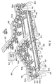
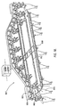
- Figure 8 shows a device 807 according to the invention in a linear embodiment, situated between a first conveyor 801 and a second conveyor 802.
- Product carriers 803 are moved along the first conveyor 801 and the second conveyor 802 in a direction indicated by arrows 804 and 805, respectively.
- legs 806 of slaughtered poultry which need to be transferred from the first conveyor 801 to the second conveyor 802.
- the product carriers 803 comprise a bracket 809 having a first bracket part 809a and a second bracket part 809b, which are arranged pivotably with respect to one another on the product carrier 803.
- the legs 806 In the closed position of the bracket 809, indicated by the reference numeral 803a, the legs 806 are substantially annularly enclosed by bracket 809 and are thus carried and supported in the product support 803.
- the device 807 comprises a stationary support 808 in the form of a plurality of flat plates which are connected to a frame (not shown).
- the support 808 is provided with two identical slots 812 which extend substantially in a straight line between a first conveyor 801 and a second conveyor 802, the slots 812 being designed to carry and support therein the legs 806.
- the two slots 812 which are referred to below as the slot 812 for the sake of simplicity, have a supply end 880 for receiving the legs 806 in the slot 812, and a discharge end 881 for discharging the legs 806 from the slot 812.
- a first and a second rotatable chain-wheel 850, 851 are arranged on the underside of the support 808 near the supply end 880 and the discharge end 881 of the slot 812, at least one chain-wheel 850, 851 being driveable.
- a drive chain 853 is arranged around the chain-wheels 850, 851, the drive chain 853 being substantially parallel to the course of the slots 812. In the configuration shown in Figure 8, the slots 812 extend substantially in a horizontal plane. To prevent the drive chain 853 from sagging, it is possible for guide elements (not shown) which are designed to support the drive chain 853, to be arranged along the course of the drive chain 853.
- a plurality of driving members 810 which are advanced in a direction indicated by arrow 827, are provided at intervals from one another on the drive chain 853. Since the drive chain 853 is guided around the chain-wheels 850, 851, the driving members 810 will move along the course of the slots 812 in a direction corresponding to that indicated by arrow 828.
- the driving members 810 are arranged in such a manner on the drive chain 853 that they are directed radially outwards.
- the dimensions of the driving members 810 and the diameter of the chain-wheels 850, 851 are selected in such a manner that the driving members 810 span all or at least part of the width of the slots 812.
- a leg 806 which is situated inside the slot 812 and in front of a driving member 810 will be carried along with the movement of the driving member 810 and consequently will be moved from the supply end 880 towards the discharge end 881.
- the slot 812 In the vicinity of its discharge end 881, the slot 812 has a rotatably driven disc-like driving member 815 which is designed to discharge the legs 806 from the slot 812 to the discharge end 881, in particular to a waiting slot 816 provided in the vicinity of the discharge end 881.
- the device 807 has a weighing device 860 which is used to weigh the legs 806 while they are being transferred from the supply end 880 to the discharge end 881.
- a leg 806 which is located at the weighing device 860 can be removed from the slots 812 by increasing the width of the corresponding slot 812 at the location of the weighing device 860.
- a slideable plate member 870 is provided, which can slide in a direction indicated by arrow 862. Whether or not a leg 806 is removed from the slot 812 depends on the detected weight.
- the detected weight of the legs 806 is fed to a control device 842, which is diagrammatically represented.
- the detected weight of the leg 806 is compared with, for example, a set value in the control device 842, on the basis of which comparison the control device 842 optionally actuates the weighing device 860 so as to release the leg 806 there. This is indicated by arrow 891.
- the product carriers 803 of the first conveyor 801 are moved towards the supply end 880 of the slot 812, specifically in such a manner that the product carriers 803 are situated just above the support 808.
- the distance between the slots 812 and the pitch of the product carriers 803 of the first conveyor 801 substantially correspond.
- the legs 806 are then no longer carried and supported by the bracket 809, but rather by the slot 812, in particular its supply end 880.
- the product carrier 803 are moved further along the first conveyor 801 in the direction of arrow 804 and, in the process, their first bracket part 809 presses against the leg 806, with the result that the leg 806 is pushed onwards in the slot 812.
- the first conveyor 801 runs upwards after the supply end 880 of the slot 812, so that the product carriers 803 are lifted away and lose contact with the legs in the slot 812. This is indicated by the reference numeral 803c.
- the legs 806 may be temporarily stored between the discharge end of the slots 812 and the weighing station 860 and are then moved out of the slot 812 into a waiting slot 816 by the disc-like driving members 815.
- the legs 806 are released to product carriers 803 which are moving along the second conveyor 802. This takes place in a similar way to that in which the legs 806 are picked up at the supply end 880 of the slot 812, except in the reverse order.
- the second conveyor 802 runs downwards, and the open product carriers 803 are moved downwards. This is indicated by the reference numeral 803d.
- the legs 806 which are to be picked up by the product carriers 803 are situated in the waiting slot 816.
- the open product carrier 803 is placed over that part of the leg 806 which projects above the slot 812 and the first bracket part 809a pushes the leg 806 out of the waiting slot 816. This is indicated by the reference numeral 803e.
- the bracket 809 is closed in a manner which is not shown but is known per se, and the leg 806 has been picked up by the product carrier 803. This is indicated by the reference numeral 803f.
- the weighing device 860 is actuated by the control device 842 in such a manner that the plate member 870, one plate member 870 for each slot 812, slides in the direction of arrow 862.
- the width of the slot 812 is increased at the location of the weighing device 860, so that it is impossible for a slaughtered animal 806 or a part thereof to be supported in the slot 812, and consequently the slaughtered animal 806 or part thereof will fall out of the slot 812 under the influence of the force of gravity, in a direction indicated by arrow 865.
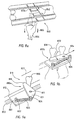
- Figures 9a and 9b show a detailed view of a driving member 810 in a first limit position 810a and a second limit position 810b.
- the driving member 810 is connected to the drive chain 853 via a support 861.
- the driving members 810 comprise an arm 819 which is connected to the support 861 in such a manner that it can pivot about an axis 811.
- the driving member 810 has a projection 821 which, via a pivot 824, is connected to a first end of a tension spring 826, the second end of the tension spring 826 being connected to the support 861 via a projection 822.
- the driving member 810 is situated in the first limit position, in which the leg 806 is being moved in the direction of arrow 827.
- the driving member 810 is in the second limit position.
- the driving members 810 In the direction indicated by the arrow 827 there are a plurality of legs 806 and the legs 806 cannot be conveyed further towards the discharge end 811 of the slot 812.
- the driving members 810 can be rotated in a direction indicated by arrow 832.
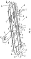
- Figure 10 shows a variant of the preferred embodiment of the device 807 shown in Figure 8, in which the slaughtered animals 806 or parts thereof are not transferred from a first conveyor to a second conveyor, but rather the slaughtered animals 806 or parts thereof, in particular entire carcasses 806, are removed from the product carriers 803, which are moving along the conveyor 801 in the direction of arrow 804, and are placed in the slots 812 in order, for example, to be weighed and are then put back in the same conveyor 801, although shifted one product carrier 803 downstream compared to their original product carrier 803.
- the slaughtered animals 806 or parts thereof can be taken back out of the product carrier 803 for a brief period further downstream, for example for a weighing or correctional treatment, before the slaughtered animals 806 or parts thereof are then hung back in the product carriers 803 shifted one product carrier 803 upstream, so that the product carriers 803 they are in then correspond to the product carriers 803 in which the slaughtered animals 806 or parts thereof were hung originally, i.e. before they passed through the device 807.
- the carcasses 806 are taken out of the product carriers 803 and put into the slots 812 and are picked up from the slots 812 by the product carriers 803 at the supply end 880 and the discharge end 881 of the slots 812 in the same way as that which has already been described above and therefore requires no further explanation.
- the carcasses 806 are weighed by the weighing device 860 arranged in the slot 812.
- Figure 11 likewise shows a variant of the device 807 shown in Figure 8, whereby the first conveyor 801 and the second conveyor 802 convey different kinds of product carriers 803.
- the first conveyor 801 is substantially at right angles to the slots 812 of the device 807, while the second conveyor is located substantially parallel to the slots 812.
- the product carriers 803 of the first conveyor 801 are moved, for example, in a direction indicated by arrow 804a. It is not necessary for the product carriers 803 of the first conveyor 810 and the product carriers 803 from the second conveyor 802 to have the same pitch, and consequently the distance between the slots 812 may vary at the supply end and at the discharge end of the slots 812.
- An expulsion mechanism 840 is arranged along the first conveyor track 801, in the vicinity of the supply end 880 of the slot 812.
- the expulsion mechanism 840 comprises an ejector which can be extended in a direction indicated by arrow 841.
- a product carrier 803 holding legs 806 which have been selected to be transferred from the first conveyor 801 to the second conveyor 802 is situated in front of the supply end 880 of the slot 812, the ejector is extended in the direction of the arrow 841, and the legs 806 are expelled from the product carrier 803 into the respective slots 812.
- the expulsion mechanism 840 may, for example, be designed in accordance with the principles of the ejector member 516 shown in Figure 6.
- Figure 12 shows a device 807 in which legs 806 are being conveyed from the supply end 880 of the slots 812 towards the discharge end 881 thereof in the manner described above.
- the legs 806 are supplied from a product carrier 803 by the expulsion mechanism 840.
- the product carrier 803 is, for example, advanced in a direction indicated by arrow 804b, along a conveyor which is not shown.
- the legs 806 are taken out of the slot 812 in the known way by a product carrier 803 which is moving along a conveyor (not shown), the product carrier 803 being moved, for example, in a direction indicated by arrow 805b.
- the device 807 is provided with two disc-like driving members 815 at the supply end 880 of the slot 812, one driving member 815 for each slot 812, for putting the legs 806 into the slot 812 from the supply end 880.
- the functions of weighing the legs 806 and removing them from the slots 812 are carried out separately by an unloading device.
- the legs 806 are weighed in the weighing device 860, and the detected weight is fed to the control device 842, as indicated by arrow 890.
- the legs 806 can be removed from the slots 812 with the aid of an unloading device 861 provided for this purpose.
- the unloading device 861 For each slot 812, the unloading device 861 has an arm 862 which is arranged on the support 808 so that it can pivot substantially in a horizontal plane. At the unloading device 861, the slot 812 has a widened section 864 in which the legs 806 can be supported by the arm 862. If a leg 806 which, for example on the basis of the detected weight, has been selected for removal from the slot 812 is situated at the unloading device 861, the arm 862 is actuated in such a manner, as indicated by arrow 891, that it rotates in the direction of the arrow 863 and thus leaves the widened section 864 clear, so that the leg 806 will fall out of the slot 812 in a direction indicated by arrow 865.
- the device 807 is provided with a processing device 871, in the case shown a marinating station.
- the processing device 871 comprises two driven conveyor belts 872 arranged along a section of the slot 812.
- the conveyor belts 872 are designed to clamp around part of the legs 806 and to move the legs 806 towards the discharge end 881 of the slot 812.
- the direction and/or speed of movement of the respective conveyor belts 872 may differ, so that a rotational movement can be imposed on the legs 806, for example in a direction indicated by an arrow 873.
- the processing device 871 is a marinating station, as shown, it is in this way possible to ensure that the legs 806 are well covered with marinade.
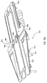
- FIGs 13a and 13b show a variant of the device 807, with a split arranged in the slots 812, so that it is possible to discharge the legs 806 sideways from the slots 812.
- a controllable switching mechanism 813 for each slot 812 is arranged on the support 808.
- the switching mechanism 813 comprises a controllable switching arm 866 which is arranged pivotably on the support 808 and can adopt a first position 866a and a second position 866b, and a rotatably driven, disc-like carrier 867.
- the switching arm 886 and the disc-like carrier 867 are controlled by control means (not shown).
- the legs 806 which are situated in the slot 812 are moved inside the slot in the direction indicated by arrow 827 by the driving members 810.
- a leg 806 has been selected for removal from the slot 812, for example on the basis of the detected weight, colour, dimensions and the like, the course of the slot 812 in the direction of arrow 827 is closed off as a result of the switching arm 866 being rotated from its first position 866a towards its second position 866b, as indicated by arrow 868. As a result, the leg 806 is forced to leave the slot 812 and is placed into a slot 869. To enable the legs 806 to be moved out of the slot 812 into the slot 869, the drive chain 853 is diverted and the drive chain 853 also covers the slot 869. A second, corresponding drive chain 853a is provided along the further course of the slot 812, i.e. that part of the slot 812 which is situated downstream of the slot 869.
- the switching arm 866 adopts its first position 866a, in which the course of the slot 812 is not closed off.
- the driveable carrier 867 is arranged along that section of the slot 812 which lies at the location of the slot 869 and along which the drive chain 853 does not extend.
- a leg 806 which is not to be moved from the slot 812 into the slot 869 is moved in the direction of arrow 827 by the driveable carrier 867 as a result of the driveable carrier 867 being rotated in a direction indicated by arrow 829.
- Legs 806 are being conveyed in the devices 807 shown in Figures 8, 11, 12, 13a and 13b. It will be clear that the embodiments shown are not restricted to conveying legs, but rather that it is also possible to use the devices shown to convey entire carcasses of poultry. It is also true for the device shown in Figure 10 that legs or other parts of slaughtered animals can be conveyed instead of entire carcasses.
- the driving members shown in the figures have an arm which is able to execute a rotary movement about a substantially vertical axis.
- the driving members it is also conceivable for the driving members to be able to execute a translational movement instead of a rotational movement. In that case, the driving members are moved along a line in order to optionally span the at least one slot.
- arms which are pivotably connected to the support and comprise force means such as compression springs, torsion springs or cylinders
- leaf springs which, instead of a pivoting movement, can execute a bending movement when the arms need to pass by slaughtered animals which have collected in the vicinity of the discharge end of the slot or slots without damaging these animals.
- a flexible, finger-like element such as a plucking finger which is normally used to remove feathers from poultry, to be used as the driving member.
Applications Claiming Priority (4)
| Application Number | Priority Date | Filing Date | Title |
|---|---|---|---|
| NL1013502A NL1013502C1 (nl) | 1999-11-05 | 1999-11-05 | Transportinrichting voor het overbrengen van slachtdieren of delen daarvan. |
| NL1013502 | 1999-11-05 | ||
| NL1013974 | 1999-12-28 | ||
| NL1013974A NL1013974C2 (nl) | 1999-11-05 | 1999-12-28 | Inrichting voor het verwerken van slachtdieren of delen daarvan. |
Publications (2)
| Publication Number | Publication Date |
|---|---|
| EP1097644A1 EP1097644A1 (en) | 2001-05-09 |
| EP1097644B1 true EP1097644B1 (en) | 2004-04-21 |
Family
ID=26643086
Family Applications (1)
| Application Number | Title | Priority Date | Filing Date |
|---|---|---|---|
| EP00203890A Expired - Lifetime EP1097644B1 (en) | 1999-11-05 | 2000-11-06 | Device for processing slaughtered animals or parts thereof |
Country Status (9)
| Country | Link |
|---|---|
| US (1) | US6997797B1 (nl) |
| EP (1) | EP1097644B1 (nl) |
| JP (1) | JP4601803B2 (nl) |
| AT (1) | ATE264621T1 (nl) |
| BR (1) | BR0005246B1 (nl) |
| DE (1) | DE60010016T2 (nl) |
| DK (1) | DK1097644T3 (nl) |
| ES (1) | ES2220339T3 (nl) |
| NL (1) | NL1013974C2 (nl) |
Cited By (1)
| Publication number | Priority date | Publication date | Assignee | Title |
|---|---|---|---|---|
| WO2007065205A1 (en) * | 2005-12-07 | 2007-06-14 | Shear Express Pty Ltd | An animal handling system |
Families Citing this family (14)
| Publication number | Priority date | Publication date | Assignee | Title |
|---|---|---|---|---|
| ES2391567T3 (es) * | 2006-11-14 | 2012-11-27 | Linco Food Systems A/S | Aparato para hacer caer aves de corral de ganchos |
| NL2001493C2 (nl) * | 2008-04-17 | 2009-10-20 | Stork P M T B V | Installatie voor het verwerken van slachtdierdelen van slachtdieren. |
| NL2002992C2 (en) * | 2009-06-10 | 2010-12-13 | Foodmate B V | Method and apparatus for automatic meat processing. |
| PL2512254T3 (pl) * | 2009-12-17 | 2019-08-30 | Marel Meat B.V. | Układ i sposób do obróbki zwierząt rzeźnych i/lub ich części |
| NL2008635C2 (nl) * | 2012-04-13 | 2013-10-16 | Marel Stork Poultry Proc Bv | Inrichting voor het wegen van slachtproducten en werkwijze voor toepassing daarvan. |
| US8500523B1 (en) * | 2012-06-07 | 2013-08-06 | Marel Meat Processing Inc. | Cutting system and method of cutting meat parts using the same |
| US9066525B2 (en) * | 2012-07-12 | 2015-06-30 | Marel Meat Processing Inc. | Shoulder positioning conveyor |
| JP6083720B2 (ja) * | 2012-10-10 | 2017-02-22 | リンコ・フード・システムズ・エイ/エス | コンベヤ上の鳥を処理するための方法および装置 |
| CN105338817B (zh) * | 2013-04-26 | 2017-12-29 | 马瑞奥肉类加工公司 | 用于处理畜体部位的系统 |
| NL2011161C2 (en) * | 2013-07-12 | 2015-01-13 | Meyn Food Proc Technology Bv | Poultry processing line comprising a series of poultry carriers and a processing unit or processing units. |
| WO2015095942A1 (pt) * | 2013-12-23 | 2015-07-02 | Silva Dirce Alves Da | Sistema transferidor de linha de produção |
| DK3508066T3 (da) * | 2018-01-03 | 2024-01-29 | Baader Food Systems Denmark As | Arrangement og fremgangsmåde til forarbejdning af fjerkræ |
| NL2024755B1 (en) * | 2020-01-24 | 2021-09-09 | Foodmate Bv | Poultry processing system for processing poultry carcasses or parts thereof |
| JP7473388B2 (ja) | 2020-05-12 | 2024-04-23 | 株式会社前川製作所 | ワーク移載装置 |
Family Cites Families (23)
| Publication number | Priority date | Publication date | Assignee | Title |
|---|---|---|---|---|
| FR1408850A (fr) | 1964-07-07 | 1965-08-20 | Fr De Transports Et Entrepots | Perfectionnements aux systèmes de changement de voie |
| US3643293A (en) * | 1970-10-13 | 1972-02-22 | Pillsbury Co | Poultry transfer apparatus and method |
| NL172295C (nl) | 1974-09-10 | 1985-10-16 | Stork Brabant Bv | Inrichting voor het overbrengen van geslacht gevogelte van een eerste naar een tweede transportbaan. |
| DE2557877C3 (de) * | 1975-12-22 | 1978-10-19 | Gefluegelschlachterei Gebr. Stolle Visbek Ue./Vechta, 2849 Visbek | Vorrichtung zum Abnehmen und Aufgeben von Schlachtgeflügel von bzw. auf Transportbahnen |
| US4178659A (en) * | 1977-10-31 | 1979-12-18 | Stork Gamco, Inc. | Transfer apparatus for poultry processing conveyor |
| US4574428A (en) * | 1984-01-16 | 1986-03-11 | Cornelis Meyn | Poultry transferring device |
| NL8400447A (nl) * | 1984-02-10 | 1985-09-02 | Stork Pmt | Inrichting voor het overbrengen van geslacht gevogelte. |
| US4627007A (en) * | 1984-02-29 | 1986-12-02 | Swift & Company | System for processing poultry carcasses |
| EP0225306A3 (en) * | 1985-12-06 | 1987-08-05 | Lindholst & Co. PTY. LTD. | Automatic "re-hang" apparatus |
| EP0235106B1 (en) * | 1986-02-18 | 1991-07-31 | Lindholst & Co. (Australia) Pty. Limited | Automatic transfer apparatus |
| NL8601179A (nl) * | 1986-05-09 | 1987-12-01 | Stork Pmt | Inrichting voor het uitwerpen van een gevogeltekarkas. |
| NL8602287A (nl) | 1986-09-10 | 1988-04-05 | Stork Pmt | Inrichting voor het selectief overbrengen van aan een transportbaan aangevoerd geslacht gevogelte naar een of meer afvoerstations onder besturing van tenminste een langs de afvoerbaan aangebracht classificatiestation. |
| NL8702887A (nl) * | 1987-12-01 | 1989-07-03 | Stork Pmt | Werkwijze en inrichting voor het bedrijven van een installatie voor het opdelen van geslacht gevogelte en voor het tijdelijk onderbreken van het transport van gevogeltekarkassen of -delen. |
| EP0357843A1 (en) * | 1988-09-09 | 1990-03-14 | Linco Holland Engineering B.V. | Device for transferring slaughtered poultry |
| NL9101856A (nl) * | 1991-11-07 | 1993-06-01 | Meyn Maschf | Werkwijze en inrichting voor het in losse onderdelen scheiden van een uit een vogel verwijderd pakket bestaande uit darmen, lever en hart met longen. |
| US5344360A (en) * | 1992-09-22 | 1994-09-06 | Hazenbroek Jacobus E | Method and apparatus for transferring a bird from one conveyor system to another |
| US5453045A (en) * | 1993-01-21 | 1995-09-26 | Systemate Holland, B.V. | System for transferring birds from one conveyor system to another with intermediate accumulator |
| NL9400665A (nl) * | 1994-04-26 | 1995-12-01 | Meyn Maschf | Werkwijze en inrichting voor het in delen scheiden van een uit een geslachte vogel verwijderd ingewandenpakket. |
| NL1000029C2 (nl) * | 1995-04-04 | 1996-10-07 | Meyn Maschf | Inrichting voor het vanaf een eerste hangtransporteur naar een tweede hangtransporteur overbrengen van geslacht gevogelte. |
| NL1004408C1 (nl) * | 1996-07-16 | 1998-01-21 | Stork Pmt | Inrichting voor het opnemen en afgeven van slachtdieren of delen daarvan. |
| US6033299A (en) * | 1998-09-11 | 2000-03-07 | Tyson Foods, Inc. | Carcass transfer apparatus |
| US6254472B1 (en) * | 2000-01-28 | 2001-07-03 | Meyn Food Processing Technology B.V. | Apparatus for suspending poultry with the legs from a hanging conveyor |
| NL1016572C2 (nl) * | 2000-11-09 | 2002-05-22 | Systemate Group Bv | Inrichting voor het overzetten van karkassen van gevogelte. |
-
1999
- 1999-12-28 NL NL1013974A patent/NL1013974C2/nl not_active IP Right Cessation
-
2000
- 2000-11-02 JP JP2000335414A patent/JP4601803B2/ja not_active Expired - Fee Related
- 2000-11-03 US US09/705,971 patent/US6997797B1/en not_active Expired - Lifetime
- 2000-11-06 ES ES00203890T patent/ES2220339T3/es not_active Expired - Lifetime
- 2000-11-06 BR BRPI0005246-9A patent/BR0005246B1/pt not_active IP Right Cessation
- 2000-11-06 DK DK00203890T patent/DK1097644T3/da active
- 2000-11-06 DE DE60010016T patent/DE60010016T2/de not_active Expired - Lifetime
- 2000-11-06 AT AT00203890T patent/ATE264621T1/de not_active IP Right Cessation
- 2000-11-06 EP EP00203890A patent/EP1097644B1/en not_active Expired - Lifetime
Cited By (1)
| Publication number | Priority date | Publication date | Assignee | Title |
|---|---|---|---|---|
| WO2007065205A1 (en) * | 2005-12-07 | 2007-06-14 | Shear Express Pty Ltd | An animal handling system |
Also Published As
| Publication number | Publication date |
|---|---|
| BR0005246A (pt) | 2001-06-05 |
| DK1097644T3 (da) | 2004-08-16 |
| DE60010016D1 (de) | 2004-05-27 |
| ATE264621T1 (de) | 2004-05-15 |
| JP2001169716A (ja) | 2001-06-26 |
| JP4601803B2 (ja) | 2010-12-22 |
| DE60010016T2 (de) | 2005-04-28 |
| BR0005246B1 (pt) | 2009-07-14 |
| EP1097644A1 (en) | 2001-05-09 |
| NL1013974C2 (nl) | 2001-05-08 |
| US6997797B1 (en) | 2006-02-14 |
| ES2220339T3 (es) | 2004-12-16 |
Similar Documents
| Publication | Publication Date | Title |
|---|---|---|
| EP1097644B1 (en) | Device for processing slaughtered animals or parts thereof | |
| EP0819382B1 (en) | Device for receiving and releasing slaughtered animals or parts thereof | |
| DK168584B1 (da) | Aggregat til selektiv overførsel af slagtet fjerkræ, der tilføres ved hjælp af en transportør, til én eller flere modtagerstationer under kontrol af i det mindste én klassificeringsstation placeret langs afleveringstransportøren | |
| US4658476A (en) | Device for conveying chickens to a slaughtering plant | |
| US4597133A (en) | Device for transferring slaughtered poultry | |
| US5453045A (en) | System for transferring birds from one conveyor system to another with intermediate accumulator | |
| CA2081182C (en) | Apparatus for removing the entrails from the abdominal cavity of poultry | |
| US5344360A (en) | Method and apparatus for transferring a bird from one conveyor system to another | |
| EP0098733B1 (en) | Egg processing system | |
| US4570295A (en) | Apparatus for transferring slaughtered poultry | |
| JPH0536290B2 (nl) | ||
| US4756056A (en) | Poultry transfer apparatus | |
| NL1013502C1 (nl) | Transportinrichting voor het overbrengen van slachtdieren of delen daarvan. | |
| NL1015742C2 (nl) | Werkwijze en inrichting voor het verwerken van te slachten pluimvee. | |
| EP0648694B1 (en) | A conveyor | |
| NL1006002C2 (nl) | Inrichting voor het lossen van kwetsbare producten, zoals eieren en fruit, vanuit een aanvoertransporteur in een onder die aanvoertransporteur geplaatste produktopvanginrichting. | |
| NL1003616C2 (nl) | Inrichting voor het opnemen en afgeven van slachtdieren of delen daarvan. | |
| USRE28666E (en) | Poultry processing method and apparatus | |
| US3482673A (en) | Packaged bakery product orienting method and mechanism | |
| CA1278156C (en) | Poultry transfer apparatus | |
| NL8802253A (nl) | Inrichting voor het uitbenen van vleesstukken voorzien van verwisselbare matrijzen. |
Legal Events
| Date | Code | Title | Description |
|---|---|---|---|
| PUAI | Public reference made under article 153(3) epc to a published international application that has entered the european phase |
Free format text: ORIGINAL CODE: 0009012 |
|
| AK | Designated contracting states |
Kind code of ref document: A1 Designated state(s): AT BE CH CY DE DK ES FI FR GB GR IE IT LI LU MC NL PT SE TR |
|
| AX | Request for extension of the european patent |
Free format text: AL;LT;LV;MK;RO;SI |
|
| 17P | Request for examination filed |
Effective date: 20010806 |
|
| AKX | Designation fees paid |
Free format text: AT BE CH CY DE DK ES FI FR GB GR IE IT LI LU MC NL PT SE TR |
|
| 17Q | First examination report despatched |
Effective date: 20030508 |
|
| GRAP | Despatch of communication of intention to grant a patent |
Free format text: ORIGINAL CODE: EPIDOSNIGR1 |
|
| GRAS | Grant fee paid |
Free format text: ORIGINAL CODE: EPIDOSNIGR3 |
|
| GRAA | (expected) grant |
Free format text: ORIGINAL CODE: 0009210 |
|
| AK | Designated contracting states |
Kind code of ref document: B1 Designated state(s): AT BE CH CY DE DK ES FI FR GB GR IE IT LI LU MC NL PT SE TR |
|
| PG25 | Lapsed in a contracting state [announced via postgrant information from national office to epo] |
Ref country code: CH Free format text: LAPSE BECAUSE OF FAILURE TO SUBMIT A TRANSLATION OF THE DESCRIPTION OR TO PAY THE FEE WITHIN THE PRESCRIBED TIME-LIMIT Effective date: 20040421 Ref country code: LI Free format text: LAPSE BECAUSE OF FAILURE TO SUBMIT A TRANSLATION OF THE DESCRIPTION OR TO PAY THE FEE WITHIN THE PRESCRIBED TIME-LIMIT Effective date: 20040421 Ref country code: AT Free format text: LAPSE BECAUSE OF FAILURE TO SUBMIT A TRANSLATION OF THE DESCRIPTION OR TO PAY THE FEE WITHIN THE PRESCRIBED TIME-LIMIT Effective date: 20040421 Ref country code: BE Free format text: LAPSE BECAUSE OF FAILURE TO SUBMIT A TRANSLATION OF THE DESCRIPTION OR TO PAY THE FEE WITHIN THE PRESCRIBED TIME-LIMIT Effective date: 20040421 Ref country code: CY Free format text: LAPSE BECAUSE OF FAILURE TO SUBMIT A TRANSLATION OF THE DESCRIPTION OR TO PAY THE FEE WITHIN THE PRESCRIBED TIME-LIMIT Effective date: 20040421 Ref country code: TR Free format text: LAPSE BECAUSE OF FAILURE TO SUBMIT A TRANSLATION OF THE DESCRIPTION OR TO PAY THE FEE WITHIN THE PRESCRIBED TIME-LIMIT Effective date: 20040421 Ref country code: FI Free format text: LAPSE BECAUSE OF FAILURE TO SUBMIT A TRANSLATION OF THE DESCRIPTION OR TO PAY THE FEE WITHIN THE PRESCRIBED TIME-LIMIT Effective date: 20040421 |
|
| REG | Reference to a national code |
Ref country code: GB Ref legal event code: FG4D |
|
| REG | Reference to a national code |
Ref country code: CH Ref legal event code: EP |
|
| REG | Reference to a national code |
Ref country code: IE Ref legal event code: FG4D |
|
| REF | Corresponds to: |
Ref document number: 60010016 Country of ref document: DE Date of ref document: 20040527 Kind code of ref document: P |
|
| PG25 | Lapsed in a contracting state [announced via postgrant information from national office to epo] |
Ref country code: SE Free format text: LAPSE BECAUSE OF FAILURE TO SUBMIT A TRANSLATION OF THE DESCRIPTION OR TO PAY THE FEE WITHIN THE PRESCRIBED TIME-LIMIT Effective date: 20040721 Ref country code: GR Free format text: LAPSE BECAUSE OF FAILURE TO SUBMIT A TRANSLATION OF THE DESCRIPTION OR TO PAY THE FEE WITHIN THE PRESCRIBED TIME-LIMIT Effective date: 20040721 |
|
| REG | Reference to a national code |
Ref country code: DK Ref legal event code: T3 |
|
| REG | Reference to a national code |
Ref country code: CH Ref legal event code: PL |
|
| PG25 | Lapsed in a contracting state [announced via postgrant information from national office to epo] |
Ref country code: LU Free format text: LAPSE BECAUSE OF NON-PAYMENT OF DUE FEES Effective date: 20041106 |
|
| PG25 | Lapsed in a contracting state [announced via postgrant information from national office to epo] |
Ref country code: IE Free format text: LAPSE BECAUSE OF NON-PAYMENT OF DUE FEES Effective date: 20041108 |
|
| PG25 | Lapsed in a contracting state [announced via postgrant information from national office to epo] |
Ref country code: MC Free format text: LAPSE BECAUSE OF NON-PAYMENT OF DUE FEES Effective date: 20041130 |
|
| REG | Reference to a national code |
Ref country code: ES Ref legal event code: FG2A Ref document number: 2220339 Country of ref document: ES Kind code of ref document: T3 |
|
| ET | Fr: translation filed | ||
| PLBE | No opposition filed within time limit |
Free format text: ORIGINAL CODE: 0009261 |
|
| STAA | Information on the status of an ep patent application or granted ep patent |
Free format text: STATUS: NO OPPOSITION FILED WITHIN TIME LIMIT |
|
| 26N | No opposition filed |
Effective date: 20050124 |
|
| REG | Reference to a national code |
Ref country code: IE Ref legal event code: MM4A |
|
| PGFP | Annual fee paid to national office [announced via postgrant information from national office to epo] |
Ref country code: ES Payment date: 20051121 Year of fee payment: 6 |
|
| PGFP | Annual fee paid to national office [announced via postgrant information from national office to epo] |
Ref country code: FR Payment date: 20051129 Year of fee payment: 6 |
|
| PGFP | Annual fee paid to national office [announced via postgrant information from national office to epo] |
Ref country code: GB Payment date: 20060928 Year of fee payment: 7 |
|
| PGFP | Annual fee paid to national office [announced via postgrant information from national office to epo] |
Ref country code: IT Payment date: 20061130 Year of fee payment: 7 |
|
| REG | Reference to a national code |
Ref country code: FR Ref legal event code: ST Effective date: 20070731 |
|
| PG25 | Lapsed in a contracting state [announced via postgrant information from national office to epo] |
Ref country code: PT Free format text: LAPSE BECAUSE OF NON-PAYMENT OF DUE FEES Effective date: 20040921 |
|
| REG | Reference to a national code |
Ref country code: ES Ref legal event code: FD2A Effective date: 20061107 |
|
| PG25 | Lapsed in a contracting state [announced via postgrant information from national office to epo] |
Ref country code: ES Free format text: LAPSE BECAUSE OF NON-PAYMENT OF DUE FEES Effective date: 20061107 Ref country code: FR Free format text: LAPSE BECAUSE OF NON-PAYMENT OF DUE FEES Effective date: 20061130 |
|
| GBPC | Gb: european patent ceased through non-payment of renewal fee |
Effective date: 20071106 |
|
| PG25 | Lapsed in a contracting state [announced via postgrant information from national office to epo] |
Ref country code: GB Free format text: LAPSE BECAUSE OF NON-PAYMENT OF DUE FEES Effective date: 20071106 |
|
| PG25 | Lapsed in a contracting state [announced via postgrant information from national office to epo] |
Ref country code: IT Free format text: LAPSE BECAUSE OF NON-PAYMENT OF DUE FEES Effective date: 20071106 |
|
| PGFP | Annual fee paid to national office [announced via postgrant information from national office to epo] |
Ref country code: NL Payment date: 20181126 Year of fee payment: 19 |
|
| PGFP | Annual fee paid to national office [announced via postgrant information from national office to epo] |
Ref country code: DK Payment date: 20181128 Year of fee payment: 19 Ref country code: DE Payment date: 20181128 Year of fee payment: 19 |
|
| REG | Reference to a national code |
Ref country code: DE Ref legal event code: R119 Ref document number: 60010016 Country of ref document: DE |
|
| REG | Reference to a national code |
Ref country code: DK Ref legal event code: EBP Effective date: 20191130 |
|
| REG | Reference to a national code |
Ref country code: NL Ref legal event code: MM Effective date: 20191201 |
|
| PG25 | Lapsed in a contracting state [announced via postgrant information from national office to epo] |
Ref country code: NL Free format text: LAPSE BECAUSE OF NON-PAYMENT OF DUE FEES Effective date: 20191201 |
|
| PG25 | Lapsed in a contracting state [announced via postgrant information from national office to epo] |
Ref country code: DK Free format text: LAPSE BECAUSE OF NON-PAYMENT OF DUE FEES Effective date: 20191130 Ref country code: DE Free format text: LAPSE BECAUSE OF NON-PAYMENT OF DUE FEES Effective date: 20200603 |