EP1096072B1 - Handgeführte Vibrationswalze - Google Patents
Handgeführte Vibrationswalze Download PDFInfo
- Publication number
- EP1096072B1 EP1096072B1 EP00309393A EP00309393A EP1096072B1 EP 1096072 B1 EP1096072 B1 EP 1096072B1 EP 00309393 A EP00309393 A EP 00309393A EP 00309393 A EP00309393 A EP 00309393A EP 1096072 B1 EP1096072 B1 EP 1096072B1
- Authority
- EP
- European Patent Office
- Prior art keywords
- roller
- hydraulic
- roller wheel
- steering
- hand guided
- Prior art date
- Legal status (The legal status is an assumption and is not a legal conclusion. Google has not performed a legal analysis and makes no representation as to the accuracy of the status listed.)
- Expired - Lifetime
Links
Images


Classifications
-
- E—FIXED CONSTRUCTIONS
- E01—CONSTRUCTION OF ROADS, RAILWAYS, OR BRIDGES
- E01C—CONSTRUCTION OF, OR SURFACES FOR, ROADS, SPORTS GROUNDS, OR THE LIKE; MACHINES OR AUXILIARY TOOLS FOR CONSTRUCTION OR REPAIR
- E01C19/00—Machines, tools or auxiliary devices for preparing or distributing paving materials, for working the placed materials, or for forming, consolidating, or finishing the paving
- E01C19/22—Machines, tools or auxiliary devices for preparing or distributing paving materials, for working the placed materials, or for forming, consolidating, or finishing the paving for consolidating or finishing laid-down unset materials
- E01C19/23—Rollers therefor; Such rollers usable also for compacting soil
- E01C19/28—Vibrated rollers or rollers subjected to impacts, e.g. hammering blows
- E01C19/282—Vibrated rollers or rollers subjected to impacts, e.g. hammering blows self-propelled, e.g. with an own traction-unit
- E01C19/283—Vibrated rollers or rollers subjected to impacts, e.g. hammering blows self-propelled, e.g. with an own traction-unit pedestrian-controlled, e.g. with safety arrangements for operator
Definitions
- the present invention relates to a hand guided vibrating roller for compacting the ground by vibrating a pair of roller wheels provided at the front and rear of a body.
- Vibrating rollers are compacting machines with roller wheels that are vibrated by a vibration generating apparatus provided at the inside of the roller wheel or the body to apply a vibratory force together with its weight to enhance the compacting effects.
- Hand guided vibrating rollers are comparatively small and lightweight among the vibrating rollers and non ride-on type machines. The operating performance of the hand guided vibrating roller is superior in the initial compaction of the asphalt pavement, the compaction of the shoulder of a road, a sidewalk, a narrow alley and others, so that the hand guided vibrating roller is widely used in the municipal road maintenance and the environmental maintenance.
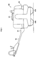
- Fig. 1 shows a conventional hand guided vibrating roller 90.
- the hand guided vibrating roller 90 comprises an engine 91, a machine 92 mounting a hydraulic pump (not shown) and others, a front roller wheel 93A and a rear roller wheel 93B arranged in parallel to support the machine 92, a hydraulic motor (not shown) for transmitting a driving force to the front roller wheel 93A and the rear roller wheel 93B by a pressure oil from the hydraulic pump, and a steering rod 95 connected to a rear end of the machine 92 over a connecting bracket 94.
- the hand guided vibrating roller 90 travels in the area to be compacted with the roller wheels 93A, 93B vibrating.
- steering n the direction needs to be changed
- a worker pushes or pulls the steering rod 95 to the left or the right to face the whole hand guided vibrating roller to the desired direction.
- the hand guided vibrating roller 90 masses 500kg to 1000kg.
- the worker holds the steering rod 95 with both hands and operates it with all his strength, which can only be handled by a skillful worker and which requires a lot of labor.
- the steering rod 95 is made longer to make the turning force smaller; however, the required force is still large.
- the steering rod 95 is made longer, because the steering rod 95 cannot be controlled in the compaction of the narrow road and narrow ditch, the steering cannot be performed.
- the worker needs to move on the compacted area right after the compaction while holding the steering rod 95, which may lower the quality of the compacted area.
- US 3814531 discloses an earth compacting machine utilizing inline vibratory roller drums.
- US 3901617 discloses a self-propelled vibratory compactor having at one end a steel roller drum and at the other a yokemounted, high-flotation pneumatic rubber tire.
- the present invention provides a hand guided vibrating roller according to claim 1.
- the supporting frame is rotatively supported by a slewing rim bearing provided right above the roller wheel, hydraulic hoses connecting the hydraulic pump with the hydraulic motor for driving the roller wheel can be inserted through the hollow portion formed at the circumference of the center of pivot of the slewing rim bearing, so that the hydraulic hoses can be piped efficiently. Therefore, the damage of the hydraulic hoses caused by the dynamic bending and tension of the hydraulic hoses due to the rotation of the supporting frame can be prevented. As a result, the durability and reliability of the hydraulic hoses can be improved.
- roller wheel can be rotated through the supporting frame by an actuator, so that the steering is not hand-operated and the fatigues due to the steering can be relieved and further the safety can be improved.
- a hydraulic cylinder may be used as the actuator.
- the supporting frame can readily be rotated by the expansion and the contraction of a cylinder rod of the hydraulic cylinder.
- a fixing member having a through hole for the hydraulic hoses may be fitted in the hollow portion of the slewing rim bearing.
- the through holes for the hydraulic hoses can be any number and any shape unless they hold the movement of the hydraulic hoses.
- the material of the fixing member is not limited but it is preferably made of rubber or synthetic resin.
- the fixing member for the hydraulic hoses can be fitted in the hollow portion, and the hydraulic hoses can be inserted into the through holes. Then, the movement of the hydraulic hoses can be held. Therefore, the hydraulic hoses can be prevented from touching the inner face of the slewing rim bearing, which protects the hydraulic hoses.
- the hand guided vibrating roller of the present invention may comprise a pressure oil supplying means connected to the hydraulic cylinder with a hydraulic hose having a directional control valve, and a directional control valve operating means for switching the directional control valve provided at a drive operating unit attached to the steering rod.
- the drive operating unit is a part for making the hand guided vibrating roller travel forward and backward, terminate, and perform the steering.
- a solenoid directional control valve herein after called a solenoid switching valve
- the hand-operated directional control valve herein after called a hand-operated switching valve
- the hydraulic cylinder can be connected to the pressure supplying means with the hydraulic hose having the directional control valve, and the directional control valve operating means can be integrated with the drive operating unit attached to the steering rod, so that the hand guided vibrating roller is superior in the operating performance.
- the directional control valve may be a solenoid directional control valve, and a solenoid directional control valve operating means for switching the solenoid directional control valve is provided at a forward-backward movement lever attached to the drive operating unit.
- the operating performance of the hand guided vibrating roller can be improved.
- the hand guided vibrating roller of the present invention may further comprise an automatic roller wheel neutralizing apparatus including a rotating position detecting means for detecting the rotating position of the roller wheel rotated in one direction around a vertical axis, and a neutral position restoring means for restoring the roller wheel to the straight forward traveling state by rotating the roller wheel in the direction opposite to the current rotating direction based on the rotating position detected by the rotating position detecting means.
- an automatic roller wheel neutralizing apparatus including a rotating position detecting means for detecting the rotating position of the roller wheel rotated in one direction around a vertical axis, and a neutral position restoring means for restoring the roller wheel to the straight forward traveling state by rotating the roller wheel in the direction opposite to the current rotating direction based on the rotating position detected by the rotating position detecting means.
- the roller wheel of the hand guided vibrating roller can automatically be made in the straight forward traveling state by operating the automatic roller wheel neutralizing apparatus without the complicated operations.
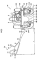
- Fig. 2 shows a hand guided vibrating roller H of the first embodiment of the present invention.
- the hand guided vibrating roller H comprises a pair of front and rear roller wheels R1 and R2 provided in parallel and a machine 30 supported by the pair of the front and rear roller wheels R1, R2.
- the machine 30 comprises left and right body frames 31A, 31B, a load holding plate 33 provided above the left and right body frames 31A, 31B over a rubber vibration isolator 36, and an upper beam 32 connected to the under portion of the left and right body frames 31A, 31B.
- the devices such as the engine E on the plate 33 are prevented from the excessive vibrations by the action of the rubber vibration isolator 36.
- front roller wheel R1 and the rear roller wheel R2 are provided to a supporting frame 10 and the body frames 31A, 31B over left and right supporting frames 21A, 21B so as to be slidable, respectively. Furthermore, there are left and right mirror plates facing to the other in the front and rear roller wheels R1, R2 (only the right mirror plate R1a of the roller wheel R1 is shown).
- a hydraulic motor M1 hydraulic motors for driving the roller wheel
- M1 hydraulic motors for driving the roller wheel
- the rotation of the hydraulic motor M1 is achieved by engaging a driving gear (not shown) provided to an output shaft of the hydraulic motor M1 with a rotating gear (not shown) provided to a wheel shaft of the roller wheel R1, which transmits the driving force to the front roller wheel R1.
- the rear roller wheel R2 receives the driving force in the same way as in the front roller wheel R1.
- a steering rod 40 is provided elongating from the rear end of the machine 30 through a connecting bracket 41.
- the steering rod 40 can be folded at a movable pin 42, which can reduce the storage space.
- the supporting frame 10 for supporting the front roller wheel R1 comprises a slewing rim bearing 50 and a steering cylinder 55, so that it can freely be rotated around the vertical axis. This construction will be described in detail referring to Figs. 3 , 4 .
- the supporting frame 10 comprises left and right supporting frames 11A, 11B, a lower beam 12 across the upper portions of the supporting frames 11A, 11B, and a bearing support 13 connected at the position above the lower beam 12 and right above the central portion of the front roller wheel R1.
- the front roller wheel R1 is rotatively supported by the left and right supporting frames 11A, 11B.
- the ball bearing type slewing rim bearing 50 is provided between the upper beam 32 of the machine 30 and the bearing support 13 so that the supporting frame 10 is supported so as to be rotated around the axis of a perpendicular line passing the center of rotation 50a of the slewing rim bearing 50.
- the bearing support 13 comprises a hole 13a for a securing pin to secure the rotating position of the slewing rim bearing 50 at an end.
- the end of the steering cylinder 55 (hydraulic cylinder) is provided at a bracket 27 fixed at the left body frame 31A, and the end of the cylinder rod 56 of the steering cylinder 55 is provided at the left end of the lower beam 12.
- the cylinder rod 56 is constructed to be retractable owing to the supply of the pressure oil from a charging pump 62 of a hydraulic motor driving hydraulic circuit Y2 (see Fig. 6 ).
- the cylinder rod 56 has the suitable length so that the expansion length changes the rotation angle ⁇ of the front roller wheel R1 (see Figs. 8A-8F ).
- the length is determined so that when the cylinder rod 56 expands most, the front roller wheel R1 is rotated 15 degrees clockwise and that when the cylinder rod 56 contracts most, the front roller wheel R1 is rotated 15 degrees counterclockwise.
- the rotation angle of the front roller wheel R1 is zero degree (hereafter called a neutral position), which means that the front roller wheel R1 is in the straight forward traveling state.
- the rotation angle ⁇ means an angle formed between a basic line m passing through the center of rotation 50a of the slewing rim bearing 50 and orthogonal to the left and right body frames 31A, 31B and an axis n with respect to the supporting frame 10 of the front roller wheel R1.
- the supporting frame 10 Since the supporting frame 10 is thus constructed, the supporting frame 10 can be rotated by the expansion and contraction of the cylinder rod 56 of the steering cylinder 55, so that the front roller wheel R1 supported by the supporting frame 10 can be rotated around the vertical axis.
- the hydraulic pump P is connected to the hydraulic motors M1, M2 through flexible hydraulic hoses .
- the hydraulic motors M1, M2 are driven by the operation of the hydraulic pump P.
- the hydraulic pump P is connected to hose lines 66A, 66B (hydraulic hoses).
- the hose line 66A pipes to the front roller wheel R1 to connect the hydraulic motor M1 contained in the front roller wheel R1.
- the hose line 66B pipes to the rear roller wheel R2 to connect the hydraulic motor M2 contained in the rear roller wheel R2.
- the front and rear hydraulic motors M1, M2 are connected through a hose line 67.
- the hydraulic hoses are connected to the right supporting frames 11B, 21B without exposing to the outside.
- the hose lines 66A, 67 which are connected to the front roller wheel R1 and which are bundled to be prevented from touching the inner surface of the slewing rim bearing 50 are inserted through the hollow portion 51 formed by the bearing support 13, the slewing rim bearing 50 and the upper beam frame 32, and clamped between the hollow portion 51 and the right supporting frame 11B so as not to touch the front roller wheel R1. Accordingly, since hose lines 66A, 67 are inserted through the hollow portion 51, the hose lines 66A, 67 can be piped near the center of rotation 50a efficiently. Therefore, the damage of the hose lines 66A, 67 caused by the repeated bending and tension of the hose lines 66A, 67 due to the rotation of the supporting frame 10, and the hand guided vibrating roller H can be miniaturized.
- the drive operating unit 70 for making the hand guided vibrating roller H travel forward and backward, stop, perform the vibrating operation, and perform the steering to the left or right direction.
- the drive operating unit 70 comprises a control handle 71 provided upright at the rear end of the steering rod 40, and a control box B arranged near the control handle 71.
- a forward-backward movement lever 72 there arranged a forward-backward movement lever 72, a throttle lever 73, a safety operation knob 74, a vibration switch 77 for operating a vibration clutch 76, a horn switch 79 for operating a horn 78 (see Fig. 7 ) and others.
- the forward-backward movement lever 72 As the forward-backward movement lever 72 is tilted forward or backward, the hand guided vibrating roller H travels forward or backward. Further, as shown in Fig. 5 , the forward-backward movement lever 72 has a steering switch 75 (means of operating solenoid directional control valve) including a left steering switch 75A, a right steering switch 75B, and a neutral switch 75C.
- a steering switch 75 (means of operating solenoid directional control valve) including a left steering switch 75A, a right steering switch 75B, and a neutral switch 75C.
- a solenoid switching valve 65 which will be describe later (see Fig. 6 ) provided at the hydraulic hoses connected between the steering cylinder 55 and the hydraulic pump P can be operated.
- the steering hydraulic circuit Y1 is provided with the hydraulic motor driving hydraulic circuit Y2.
- the hydraulic motor driving hydraulic circuit Y2 connects the hydraulic pump P (variable capacity type) driven by the engine E to the hydraulic motors M1, M2 with the hydraulic hoses.
- the charging pump 62 connected with the oil tank 63 changes the predetermined amount of oil and supplies the oil for the oil leakage in the hydraulic motor driving hydraulic circuit Y2.
- the hydraulic pump P can change the flow of the pressure oil in the reverse direction. Owing to the flowing direction of the pressure oil, the rotating direction of the front and rear roller wheels R1, R2 can be changed through the hydraulic motors M1, M2. Furthermore, when the forward-backward movement lever 72 is in the neutral position, the oil supply from the hydraulic pump P is terminated.
- the steering hydraulic circuit Y1 is a circuit for connecting the oil tank 63 to the charging pump 62 and the steering cylinder 55 with the hydraulic hoses.
- the pressure oil is supplied from the charging pump 62 (means of supplying pressure oil) to one of the rooms of the steering cylinder 55.
- the solenoid switching valve 65 excites and degausses left and right solenoids 65A, 65B by turning on or off left and right steering switches 75A, 75B attached to the forward-backward movement lever 72, thereby to switch the hydraulic circuits. Furthermore, the supply of pressure oil to the steering cylinder 55 can be terminated by operating the neutral switch 75C.
- the cylinder rod 56 contracts when the left solenoid 65A is energized while the cylinder rod 56 expands when the right solenoid 65B is energized.
- left steering switch 75A and the right steering switch 75B send the oil to the steering cylinder 55 only when they are pushed. On the other hand, when they are not pushed, the oil sending to the steering cylinder 55 is terminated.
- the drain hose line connecting the hydraulic motors M1, M2 with the oil tank 63 is not provided; however, a drain hose line 68 shown by a dotted line in Fig. 6 which shows a hand guided vibrating roller H' of the second embodiment of the present invention may be provided.
- the charging pump 62 for sending the oil to the hydraulic motor driving hydraulic circuit Y2 is used as the constituting element of the pressure oil supplying means for sending oil to the steering cylinder 55, so that another hydraulic pump or others for sending oil to the steering cylinder 55 is not required.
- another hydraulic pump can be used therefor.
- the solenoid switching valve 65 is used as a directional control valve; however, the hand-operated switching valve may be used as the directional control valve.
- a steering lever (means of operating a directional control valve) is provided to the steering rod 40 and the steering lever is connected to the hand-operated switching valve with a control cable, which can obtain the same achievement.
- roller wheel R1 which is rotative with the slewing rim bearing 50 is called a directional roller wheel R1.
- the automatic roller wheel neutralizing apparatus T is an apparatus for automatically restoring the directional roller wheel R1 to the straight forward traveling state when the directional roller wheel R1 is rotated in one direction clockwise or counterclockwise, which is operated by pushing the neutral switch 75C of the steering switch 75.
- the automatic roller wheel neutralizing apparatus T comprises a rotating position detecting means for detecting the rotating position of the directional roller wheel R1, and a neutral position restoring means for restoring the directional roller wheel R1 in the straight forward traveling state.
- the rotating position detecting means comprises a guide plate 26 bolted to the bearing support 13 of the supporting frame 10, and two left and right limit switches 25A, 25B attached to the upper beam 32 of the machine 30 over the brackets 28A, 28B.
- the guide plate 26 is a curved member concentric with the center of rotation 50a of the slewing rim bearing 50 and includes a notch 26a (see Figs. 8A, 8B , 8C ) for releasing the conducting state of the left and right limit switches 25A, 25B at the outer circumference.
- the notch 26a is formed to have the length corresponding to the maximum rotating angle of the directional roller wheel R1 at the center of the central portion of the guide plate (in the present embodiment, the portion corresponding to the clockwise direction of 15 degrees and the counterclockwise direction of 15 degrees).
- the guide plate 26 is placed at the position where the notch 26a is in the bilateral symmetry with the base line m when the directional roller wheel R1 is in the straight forward traveling state. Further, the guide plate 26 is arranged so that in a case of the rotating angle e of zero degree, the left and right limit switches 25A, 25B are placed at both ends of the notch 26a.
- the conducting state of the left and right limit switches 25A, 25B are both released. Further, in the case that the directional roller wheel R1 is rotated counterclockwise or clockwise, the left or right switch 25A or 25B is conducted. Therefore, the rotation of the directional roller wheel R1 can be detected from the conducting state of the left or right limit switch 25A or 25B.
- the neutral position restoring means is means of restoring the directional roller wheel R1 to the straight forward traveling state by rotating it in the direction opposite to the rotating direction of the rotating position detected by the rotating position detecting means.
- the electric circuit constituting the neutral position restoring means will be explained.
- the steering switch 75 together with the vibration switch 77 and the horn switch 79 is connected to a plus terminal of a battery 80 over a starting switch 81.
- the left and right steering switches 75A, 75B and the neutral switch 75C which constitute the steering switch 75 are connected in parallel, and the outputs of the left and right steering switches 75A, 75B are connected to the inputs of the left and right solenoids 65A, 65B, respectively.
- the output of the neutral switch 75C is diverged and connected to the inputs of the left and right limit switches 25A, 25B, and the outputs of the limit switches 25A, 25B are connected to the inputs of the left and right solenoids 65A, 65B, respectively.
- the directional wheel roller R1 in a case that the directional wheel roller R1 is rotated in one direction, the clockwise or counterclockwise direction (for example, in the case of the clockwise rotation, see Figs. 8E, 8F ), as the neutral switch 75C is pushed, the limit switch (left limit switch 25A) is conducted, and the solenoid (left solenoid 65A) acting to prevent the rotation is energized. Accordingly, the passage of the solenoid switching valve 65 is switched, and the cylinder rod 56 contracts. Then, the directional roller wheel R1 is rotated in the direction (counterclockwise direction) opposite to the rotating direction.
- the directional roller wheel R1 is rotated clockwise but in a case of the counterclockwise rotation, the operation is the same as above.
- the automatic roller wheel neutralizing apparatus T is an apparatus for automatically restoring the directional roller wheel R1 to the straight forward traveling state and comprises the rotating position detecting means and the neutral position restoring means.
- both means are formed in the integral configuration; however, each can be used independently.
- a position sensor for detecting the position of the cylinder rod 56 can be provided in the steering cylinder 55, which achieves the same operation as in the above-described embodiment.
- an electric circuit (rotating position restoring means) for energizing the left solenoid 65A or the right solenoid 65B until the directional roller wheel R1 is in the neutral position on the basis of the length of the cylinder rod 56 may be formed, thereby to restore the cylinder rod 56 to the neutral position.
- the length L of the rear portion of the hand guided vibrating roller H is a horizontal length L from the rear end face of the control handle 71 (holding portion) of the steering rod 40 to the rear end face of the rear roller wheel R2 (see Fig. 2 ).
- the length L is preferably from 0.7m to 1.25m.
- the steering rod 40 since the steering rod 40 is not used in the steering, the steering rod 40 does not have to be provided, or a very short steering rod may be used. However, in such a case, during the compacting operation, if the worker comes too closer to the rear roller wheel R2, the rear roller wheel R2 may step on his foot or the worker may be injured accidentally due to the vibration or the reaction of the steering rod. Therefore, the preferred range of the length L of the rear portion is determined for the safety purpose.
- a starter switch (not shown) provided at the steering rod 40 of the hand guided vibrating roller H is turned on to drive the engine E.
- the forward-backward movement lever 72 is operated to travel the hand guided vibrating roller H in the desired direction.
- the vibration may be started if required.
- the steering switch for the desired direction of the steering e.g., the right steering switch 75B is pushed.
- the right solenoid 65B is energized and the passage of the solenoid switching valve 65 is switched to send the oil to the steering cylinder 55.
- the cylinder rod 56 expands and the front roller wheel R1 is rotated clockwise over the supporting frame 10 (see Figs. 8E, 8F ).
- the neutral switch 75C is pushed to operate the automatic roller wheel neutralizing apparatus T (see Figs. 8C, 8D ).
- the left steering switch 75A is pushed.
- the left solenoid 65A is energized and the passage of the solenoid switching valve 65 is switched.
- the cylinder rod 56 contracts and the front roller wheel R1 is rotated counterclockwise over the supporting frame 10 (see Figs. 8A, 8B ).
- the conventional operation that the worker holds the steering rod with both hands to operate it with all his strength is not needed.
- the worker can operate the steering with one hand and one finger, so that the hand guided vibrating roller has the improved operating performance.
- the forward-backward movement lever 72 is hand-operated; however, an electric circuit for controlling the rotating direction of the front and rear roller wheels R1, R2 and means of operating the electric circuit can be provided and the steering switch and the means of operating the electric circuit may be remote-controlled, which further improves the usefulness of the operation.
- a hand guided vibrating roller H' according to the second embodiment of the present invention is different from the one of the first embodiment in the presence of a supporting structure for the hydraulic hoses and the drain hose line 68 in the hollow portion of the slewing rim bearing 50.
- the slewing rim bearing 50 comprises an inner ring 50A' placed above the circular bearing support 13 welded at the center of the lower beam 12, an outer ring 50B' outside the inner ring 50A' and a rotating unit 50C' provided there between.
- the inner ring 50A' is fixed at the lower beam 12 with a bolt 52A and the outer ring 50B' is fixed at the upper beam 32 with the bolt 52B, and both can be rotated around the center of rotation 50a.
- the fixing member 54 is a cylindrical member having the outer diameter as same as the inner diameter of the inner ring 50A' and has a locking step G at the bottom with the smaller diameter. The locking step G is locked with the end 13a of the bearing support 13 to be inserted in the hollow portion 51'.
- the through hole 54a has a suitable size for holding the movement of the hydraulic hoses.
- the hose lines 66A, 67 which are the hydraulic hoses and the drain hose line 68 connecting the hydraulic motor M1 with the oil tank 63 are inserted and held in the through hole 54a. Accordingly, the hose lines 66A, 67 and the drain hose line 68 are prevented from touching the inner ring 50A' of the slewing rim bearing 50, which protects the hose lines.
- the fixing member 54 can hold the movement of the hose lines 66A, 67 and the drain hose line 68, which is very useful.
- the through hole for the fixing member 54 is not limited to the circular hole. It may be a triangular-shaped through hole 54B (see a fixing member 54B of Fig. 11A ). Further, plural through holes may be formed and each hydraulic hose is inserted in one through hole. For example, as shown in Fig. 11B , one through hole is formed by a narrow groove 54c' cut from the fixing member 54C towards the circumference and a small circular hole 54c adjacent to the narrow groove 54c'. In this case, when the drain hose line is not provided as in the first embodiment, the number of the through holes is the number of the hydraulic hoses.
- the fixing member may be divided into an upper portion 54D and a lower portion 54D' and the same through holes 54d, 54d' are formed in each portion.
- the hydraulic hoses or drain hose line are inserted in the through holes 54d, 54d'.
- one of the upper and lower portions 54D, 54D' is rotated (e.g., the upper portion 54D) (see Figs. 12C, 12D ) to adjust the space between the through holes 54d, 54d' to hold the hydraulic hoses or drain hose line (see Figs. 12E, 12F ).
- the directional roller wheel is the front roller wheel R1 but it may be the rear roller wheel R2 or it may be both of the front and rear roller wheels R1 and R2.
- the steering switch 75 as the solenoid switching valve operating means is provided to the forward-backward movement lever 72 but it can be provided to other portion.
- the fixing member for the hydraulic hoses can be used to fix the cable of the electric product and wiring.
- the directional roller wheel can be rotated through the supporting frame by an actuator such as the hydraulic cylinder, the steering is not hand-operated and the fatigues of the steering can be relieved and the safety can be improved. Further, the worker does not need to operate the steering rod by hand to rotate the supporting frame, so that the long steering rod is not needed and the length of the rear portion of the hand guided vibrating roller can be made short comparing to the conventional hand guided vibrating roller (conventionally the length is about 1.4m).
- the length of the rear portion of the roller can be made small, so that the steering can be performed efficiently in the compacting operation of the narrow road or the narrow ditch.
- the hydraulic cylinder is connected to the pressure oil supplying means with the hydraulic hoses having the directional control valve, and the directional control valve operating means for operating the switch of the directional control valve is provided to the drive operating unit of the steering rod, so that the steering can be performed by operating only the drive operating unit. Accordingly, the conventional operation that the worker holds the steering rod with both hands to operate it with all his strength is not needed. The worker can operate the steering with one hand and one finger, so that the hand guided vibrating roller has the improved operating performance.
- the hand guided vibrating roller can be operated from the side of the steering rod, so that it can be operated outside the work area under the compacting operation, which can improve the quality of the compacted area.
- the directional roller wheel of the hand guided vibrating roller is automatically made in the straight forward traveling state, so that the operating performance can sharply be enhanced.
- the fixing member for the hydraulic hoses is fitted in the hollow portion to hold the movement of the hydraulic hoses inserted therein, so that the hydraulic hoses are prevented from touching the inner face of the slewing rim bearing, which protects the hydraulic hoses.
Landscapes
- Engineering & Computer Science (AREA)
- Architecture (AREA)
- Civil Engineering (AREA)
- Structural Engineering (AREA)
- Road Paving Machines (AREA)
- Handcart (AREA)
Claims (5)
- Handgeführte vibrierende Walze (H), die Folgendes umfasst:ein Paar vordere (R1) und hintere (R2) Walzenräder, die parallel zueinander bereitgestellt sind;eine Maschine (30), die durch das Paar vordere und hintere Walzenräder (R1, R2) gelagert wird,eine Hydraulikpumpe (P), die an der Maschine (30) angebracht ist,einen Hydraulikmotor (M1, M2), der in jedem Walzenrad bereitgestellt ist, um die Walzenräder anzutreiben,eine Lenkstange (40), die sich von dem hinteren Abschnitt der Maschine (30) erstreckt,einen Trägerrahmen (10), der um eine vertikale Achse frei drehbar ist und zumindest eines der Walzenräder lagert, undeinen Aktuator (55, 56), um den Trägerrahmen (10) zu drehen;dadurch gekennzeichnet, dass der Trägerrahmen (10) drehbar durch ein Drehkranzlager (50) gelagert wird, das unmittelbar oberhalb des gelagerten Walzenrads bereitgestellt ist, und die Hydraulikpumpe (P) und der Hydraulikmotor zum Antrieb des gelagerten Walzenrads durch Hydraulikschläuche (66A, 67, 68) verbunden sind, die in einen hohlen Abschnitt (51, 51') des Drehkranzlagers (50) eingeführt sind.
- Handgeführte vibrierende Walze nach Anspruch 1, worin ein Befestigungselement (54) mit einem oder mehreren Durchgangslöchern (54a, 54b, 54c, 54d, 54d') für die Hydraulikschläuche in den hohlen Abschnitt (51, 51') des Drehkranzlagers (50) eingepasst ist.
- Handgeführte vibrierende Walze nach Anspruch 1 oder 2, worin der Aktuator ein Hydraulikzylinder (55) mit einer Zylinderstange (56) ist und der Trägerrahmen (10) durch die Ausdehnung und Kontraktion der Zylinderstange (56) des Aktuators gedreht wird, wobei ein Mittel zur Zufuhr von Drucköl zu dem Hydraulikzylinder durch einen Hydraulikschlauch mit einem Richtungsschaltungsmagnetventil (65) mit dem Hydraulikzylinder verbunden ist und wobei ein Betätigungsmittel (75A, 75B) für das Richtungsschaltungsmagnetventil zum Umschalten des Richtungsschaltungsmagnetventils an einem Vorwärts-/Rückwärtsbewegungshebel (72) bereitgestellt ist, der an einer Antriebsbetriebseinheit (70) der Lenkstange (40) angebracht ist.
- Handgeführte vibrierende Walze nach Anspruch 3, worin die handgeführte vibrierende Walze eine automatische Vorrichtung zur Wiederherstellung der Nullstellung (T) umfasst, die Folgendes umfasst:ein Rotationspositionsdetektionsmittel zur Detektion der Rotationsposition des gelagerten Walzenrads, das um eine vertikale Achse in eine Richtung gedreht wird, undein Nullstellungsrückstellmittel, um das gelagerte Walzenrad in den Zustand rückzustellen, in dem es sich geradeaus nach vorwärts bewegt, indem das Walzenrad auf Grundlage der durch das Rotationspositionsdetektionsmittel detektierten Rotationsposition in die der aktuellen Rotationsrichtung entgegengesetzte Richtung gedreht wird.
- Handgeführte vibrierende Walze nach Anspruch 1, worin das Drehkranzlager (50) Folgendes umfasst: einen inneren Ring (50A'), der oberhalb eines kreisförmigen Lagerträgers (13) angeordnet ist, der in der Mitte eines unteren Balkens (12) angeschweißt ist, wobei der innere Ring (50A') an dem unteren Balken (12) befestigt ist; einen äußeren Ring (50B') außerhalb des inneren Rings, wobei der äußere Ring (50B') an einem oberen Balken (32) befestigt ist, und eine Rotationseinheit (50C'), die zwischen diesen bereitgestellt ist, wobei der hohle Abschnitt (51, 51') innerhalb des inneren Rings (50A') angeordnet ist.
Applications Claiming Priority (4)
| Application Number | Priority Date | Filing Date | Title |
|---|---|---|---|
| JP30647599 | 1999-10-28 | ||
| JP30647599 | 1999-10-28 | ||
| JP2000286916 | 2000-09-21 | ||
| JP2000286916A JP3725769B2 (ja) | 1999-10-28 | 2000-09-21 | ハンドガイドローラ |
Publications (3)
| Publication Number | Publication Date |
|---|---|
| EP1096072A2 EP1096072A2 (de) | 2001-05-02 |
| EP1096072A3 EP1096072A3 (de) | 2003-02-12 |
| EP1096072B1 true EP1096072B1 (de) | 2012-08-15 |
Family
ID=26564732
Family Applications (1)
| Application Number | Title | Priority Date | Filing Date |
|---|---|---|---|
| EP00309393A Expired - Lifetime EP1096072B1 (de) | 1999-10-28 | 2000-10-25 | Handgeführte Vibrationswalze |
Country Status (4)
| Country | Link |
|---|---|
| US (1) | US6409425B1 (de) |
| EP (1) | EP1096072B1 (de) |
| JP (1) | JP3725769B2 (de) |
| NZ (1) | NZ507698A (de) |
Cited By (2)
| Publication number | Priority date | Publication date | Assignee | Title |
|---|---|---|---|---|
| DE102017000951A1 (de) | 2017-02-02 | 2018-08-02 | Bomag Gmbh | Handgeführte Bodenverdichtungswalze mit Lenkbetriebsmodus und Verfahren zur Lenkung einer handgeführten Bodenverdichtungswalze |
| WO2023086309A1 (en) * | 2021-11-10 | 2023-05-19 | Milwaukee Electric Tool Corporation | Plate compactor |
Families Citing this family (19)
| Publication number | Priority date | Publication date | Assignee | Title |
|---|---|---|---|---|
| DE10210049B4 (de) * | 2002-03-07 | 2004-03-25 | Abg Allgemeine Baumaschinen-Gesellschaft Mbh | Verdichtungswalze |
| US7416365B2 (en) * | 2003-06-18 | 2008-08-26 | Mikasa Sangyo Co., Ltd. | Safety device for backward movement of vibration roller |
| US7857544B2 (en) * | 2008-10-03 | 2010-12-28 | Caterpillar Inc | Extension plate for a compactor |
| US8376655B2 (en) * | 2008-10-03 | 2013-02-19 | Caterpillar Paving Products Inc. | Compactor with smooth hose routing |
| US7853373B2 (en) * | 2009-02-10 | 2010-12-14 | Precise Path Robotics, Inc. | System for steering a traction drum driven mobile object |
| DE102011115008A1 (de) * | 2011-10-06 | 2013-04-11 | Wacker Neuson Produktion GmbH & Co. KG | Elektrowerkzeug mit Schutzhaube |
| US8414220B1 (en) * | 2012-02-09 | 2013-04-09 | Josei Techno Co., Ltd. | Apparatus for flattening floor |
| JP5916588B2 (ja) * | 2012-11-09 | 2016-05-11 | 日立建機株式会社 | 転圧機械 |
| JP6223146B2 (ja) * | 2013-11-26 | 2017-11-01 | 酒井重工業株式会社 | 振動締固め機械のロール支持構造および組み付け方法 |
| CA2868740C (en) * | 2014-05-22 | 2017-01-10 | Vibco, Inc. | Vibratory pothole packer |
| JP6371238B2 (ja) * | 2015-02-27 | 2018-08-08 | 株式会社日立建機カミーノ | ハンドガイドローラ |
| US9593453B2 (en) * | 2015-03-27 | 2017-03-14 | Wacker Neuson Production Americas Llc | Walk-behind compaction roller incorporating noise reduction measures |
| US9717184B1 (en) * | 2016-07-11 | 2017-08-01 | American-Iowa Manufacturing Inc. | Mechanical drive roller |
| US10662591B2 (en) | 2018-01-05 | 2020-05-26 | Vibco, Inc. | Forward and reversible self-propelled vibratory pothole packer |
| CN108824135A (zh) * | 2018-06-07 | 2018-11-16 | 黄绍规 | 一种建筑用沥青浇筑装置 |
| KR102288139B1 (ko) * | 2019-01-22 | 2021-08-12 | 한국도로공사 | 포터블 포장 기구 및 이를 구비한 도로포장 장치 |
| CN111188245B (zh) * | 2020-01-13 | 2022-02-08 | 廊坊市交通公路工程有限公司 | 一种用于沥青混凝土压实度实时连续检测的振动压路机 |
| CN111379207B (zh) * | 2020-03-26 | 2021-11-05 | 张晓奎 | 一种用于混凝土道路施工的手持式抹光设备 |
| CN112681074B (zh) * | 2020-12-23 | 2022-08-26 | 澧县永兴商品混凝土有限责任公司 | 一种用于道路施工的移动式混凝土振捣装置 |
Family Cites Families (8)
| Publication number | Priority date | Publication date | Assignee | Title |
|---|---|---|---|---|
| CH454201A (de) * | 1966-03-18 | 1968-04-15 | Edgar Steck Ferdinand | Strassenwalze |
| US3737243A (en) * | 1971-09-07 | 1973-06-05 | Ingersoll Rand Co | Soil and pavement compacting machine |
| US3814531A (en) * | 1971-12-13 | 1974-06-04 | Koehring Co | Articulated roller assembly |
| US3901617A (en) * | 1972-01-14 | 1975-08-26 | Hyster Co | Self-propelled vibratory compactor vehicle |
| US4109742A (en) * | 1977-02-24 | 1978-08-29 | Iowa Manufacturing Company | Steering and width controls for expandable tandem rollers |
| SE502269C2 (sv) * | 1994-01-31 | 1995-09-25 | Dynapac Heavy Equipment Ab | Styrsystem för vägvältar |
| JP3365960B2 (ja) * | 1998-07-07 | 2003-01-14 | 株式会社タイキョク | 手動操舵式ハンドガイドローラ |
| JP2000170117A (ja) | 1998-12-10 | 2000-06-20 | Katsuji Obara | ハンドガイドローラ |
-
2000
- 2000-09-21 JP JP2000286916A patent/JP3725769B2/ja not_active Expired - Lifetime
- 2000-10-20 NZ NZ507698A patent/NZ507698A/en not_active IP Right Cessation
- 2000-10-25 EP EP00309393A patent/EP1096072B1/de not_active Expired - Lifetime
- 2000-10-30 US US09/698,194 patent/US6409425B1/en not_active Expired - Lifetime
Cited By (2)
| Publication number | Priority date | Publication date | Assignee | Title |
|---|---|---|---|---|
| DE102017000951A1 (de) | 2017-02-02 | 2018-08-02 | Bomag Gmbh | Handgeführte Bodenverdichtungswalze mit Lenkbetriebsmodus und Verfahren zur Lenkung einer handgeführten Bodenverdichtungswalze |
| WO2023086309A1 (en) * | 2021-11-10 | 2023-05-19 | Milwaukee Electric Tool Corporation | Plate compactor |
Also Published As
| Publication number | Publication date |
|---|---|
| US6409425B1 (en) | 2002-06-25 |
| JP2001193010A (ja) | 2001-07-17 |
| JP3725769B2 (ja) | 2005-12-14 |
| EP1096072A2 (de) | 2001-05-02 |
| NZ507698A (en) | 2001-09-28 |
| EP1096072A3 (de) | 2003-02-12 |
Similar Documents
| Publication | Publication Date | Title |
|---|---|---|
| EP1096072B1 (de) | Handgeführte Vibrationswalze | |
| JP3953261B2 (ja) | コンクリート仕上げトロエル及びその操縦方法 | |
| US5713418A (en) | Vibratory compactor | |
| US7237630B2 (en) | Steering arrangement for a work machine | |
| WO2022190650A1 (ja) | 建設機械 | |
| JP2727050B2 (ja) | 可変振幅振動ローラの起振装置 | |
| KR100600832B1 (ko) | 핸드 가이드 로울러 | |
| JP3639375B2 (ja) | 操向機能を有する締固め機械 | |
| JPH09242123A (ja) | 建設機械の操作装置 | |
| JP3771402B2 (ja) | 油圧走行車両の走行制御装置 | |
| JPH07197415A (ja) | 振動ローラの起振方法およびその装置 | |
| JP2794270B2 (ja) | 可変振幅振動ローラの起振装置 | |
| US20240034403A1 (en) | Compaction Machine Steering System | |
| JP3450202B2 (ja) | エンドミルカッタ式作業車両 | |
| JPH0971263A (ja) | クローラ式走行車の走行操作装置 | |
| JP6944025B2 (ja) | 作業車両 | |
| JP2600986Y2 (ja) | 操作レバー操作装置 | |
| JPH0154482B2 (de) | ||
| JPH10276575A (ja) | 自走式グリ−ン転圧用車両 | |
| JPH07228485A (ja) | 建設機械における走行体の伸縮検出装置 | |
| JPH048635A (ja) | 自走式作業車両 | |
| JP6112424B2 (ja) | 作業機械 | |
| JP3216121B2 (ja) | ハンドガイド式転圧機械 | |
| JP4170880B2 (ja) | 旋回作業機 | |
| CA1059878A (en) | Skid-steered tractor vehicle combined steering lever and auxiliary control with self-centering mechanism |
Legal Events
| Date | Code | Title | Description |
|---|---|---|---|
| PUAI | Public reference made under article 153(3) epc to a published international application that has entered the european phase |
Free format text: ORIGINAL CODE: 0009012 |
|
| AK | Designated contracting states |
Kind code of ref document: A2 Designated state(s): AT BE CH CY DE DK ES FI FR GB GR IE IT LI LU MC NL PT SE |
|
| AX | Request for extension of the european patent |
Free format text: AL;LT;LV;MK;RO;SI |
|
| PUAL | Search report despatched |
Free format text: ORIGINAL CODE: 0009013 |
|
| AK | Designated contracting states |
Designated state(s): AT BE CH CY DE DK ES FI FR GB GR IE IT LI LU MC NL PT SE |
|
| AX | Request for extension of the european patent |
Extension state: AL LT LV MK RO SI |
|
| 17P | Request for examination filed |
Effective date: 20030612 |
|
| AKX | Designation fees paid |
Designated state(s): DE FR GB IT SE |
|
| 17Q | First examination report despatched |
Effective date: 20050614 |
|
| 17Q | First examination report despatched |
Effective date: 20050614 |
|
| GRAP | Despatch of communication of intention to grant a patent |
Free format text: ORIGINAL CODE: EPIDOSNIGR1 |
|
| GRAS | Grant fee paid |
Free format text: ORIGINAL CODE: EPIDOSNIGR3 |
|
| GRAA | (expected) grant |
Free format text: ORIGINAL CODE: 0009210 |
|
| AK | Designated contracting states |
Kind code of ref document: B1 Designated state(s): DE FR GB IT SE |
|
| REG | Reference to a national code |
Ref country code: GB Ref legal event code: FG4D |
|
| REG | Reference to a national code |
Ref country code: DE Ref legal event code: R096 Ref document number: 60047419 Country of ref document: DE Effective date: 20121011 |
|
| REG | Reference to a national code |
Ref country code: SE Ref legal event code: TRGR |
|
| PLBE | No opposition filed within time limit |
Free format text: ORIGINAL CODE: 0009261 |
|
| STAA | Information on the status of an ep patent application or granted ep patent |
Free format text: STATUS: NO OPPOSITION FILED WITHIN TIME LIMIT |
|
| 26N | No opposition filed |
Effective date: 20130516 |
|
| REG | Reference to a national code |
Ref country code: DE Ref legal event code: R097 Ref document number: 60047419 Country of ref document: DE Effective date: 20130516 |
|
| PGFP | Annual fee paid to national office [announced via postgrant information from national office to epo] |
Ref country code: GB Payment date: 20131023 Year of fee payment: 14 |
|
| PGFP | Annual fee paid to national office [announced via postgrant information from national office to epo] |
Ref country code: IT Payment date: 20131028 Year of fee payment: 14 |
|
| GBPC | Gb: european patent ceased through non-payment of renewal fee |
Effective date: 20141025 |
|
| PG25 | Lapsed in a contracting state [announced via postgrant information from national office to epo] |
Ref country code: GB Free format text: LAPSE BECAUSE OF NON-PAYMENT OF DUE FEES Effective date: 20141025 |
|
| PG25 | Lapsed in a contracting state [announced via postgrant information from national office to epo] |
Ref country code: IT Free format text: LAPSE BECAUSE OF NON-PAYMENT OF DUE FEES Effective date: 20141025 |
|
| REG | Reference to a national code |
Ref country code: FR Ref legal event code: PLFP Year of fee payment: 17 |
|
| PGFP | Annual fee paid to national office [announced via postgrant information from national office to epo] |
Ref country code: FR Payment date: 20160919 Year of fee payment: 17 |
|
| REG | Reference to a national code |
Ref country code: FR Ref legal event code: ST Effective date: 20180629 |
|
| PG25 | Lapsed in a contracting state [announced via postgrant information from national office to epo] |
Ref country code: FR Free format text: LAPSE BECAUSE OF NON-PAYMENT OF DUE FEES Effective date: 20171031 |
|
| PGFP | Annual fee paid to national office [announced via postgrant information from national office to epo] |
Ref country code: SE Payment date: 20191010 Year of fee payment: 20 Ref country code: DE Payment date: 20191015 Year of fee payment: 20 |
|
| REG | Reference to a national code |
Ref country code: DE Ref legal event code: R071 Ref document number: 60047419 Country of ref document: DE |