EP1093151A2 - Massenspektrometer, Massenspektrometrie und Überwachungssystem - Google Patents
Massenspektrometer, Massenspektrometrie und Überwachungssystem Download PDFInfo
- Publication number
- EP1093151A2 EP1093151A2 EP00120100A EP00120100A EP1093151A2 EP 1093151 A2 EP1093151 A2 EP 1093151A2 EP 00120100 A EP00120100 A EP 00120100A EP 00120100 A EP00120100 A EP 00120100A EP 1093151 A2 EP1093151 A2 EP 1093151A2
- Authority
- EP
- European Patent Office
- Prior art keywords
- ion
- chamber
- opening portion
- electrode
- gas
- Prior art date
- Legal status (The legal status is an assumption and is not a legal conclusion. Google has not performed a legal analysis and makes no representation as to the accuracy of the status listed.)
- Granted
Links
Images


Classifications
-
- H—ELECTRICITY
- H01—ELECTRIC ELEMENTS
- H01J—ELECTRIC DISCHARGE TUBES OR DISCHARGE LAMPS
- H01J49/00—Particle spectrometers or separator tubes
- H01J49/02—Details
- H01J49/10—Ion sources; Ion guns
- H01J49/16—Ion sources; Ion guns using surface ionisation, e.g. field-, thermionic- or photo-emission
- H01J49/168—Ion sources; Ion guns using surface ionisation, e.g. field-, thermionic- or photo-emission field ionisation, e.g. corona discharge
-
- H—ELECTRICITY
- H01—ELECTRIC ELEMENTS
- H01J—ELECTRIC DISCHARGE TUBES OR DISCHARGE LAMPS
- H01J49/00—Particle spectrometers or separator tubes
- H01J49/02—Details
- H01J49/04—Arrangements for introducing or extracting samples to be analysed, e.g. vacuum locks; Arrangements for external adjustment of electron- or ion-optical components
- H01J49/0422—Arrangements for introducing or extracting samples to be analysed, e.g. vacuum locks; Arrangements for external adjustment of electron- or ion-optical components for gaseous samples
-
- G—PHYSICS
- G01—MEASURING; TESTING
- G01N—INVESTIGATING OR ANALYSING MATERIALS BY DETERMINING THEIR CHEMICAL OR PHYSICAL PROPERTIES
- G01N30/00—Investigating or analysing materials by separation into components using adsorption, absorption or similar phenomena or using ion-exchange, e.g. chromatography or field flow fractionation
- G01N30/02—Column chromatography
- G01N30/62—Detectors specially adapted therefor
- G01N30/72—Mass spectrometers
- G01N30/7233—Mass spectrometers interfaced to liquid or supercritical fluid chromatograph
- G01N30/724—Nebulising, aerosol formation or ionisation
Definitions
- the present invention relates to an ion source, a mass spectrometer and mass spectrometry employing the ion source, and monitoring system employing the same or a monitor employing the ion source.
- sample ionizing method is an atmospheric pressure chemical ionization employing corona discharge.
- corona discharge As disclosed in Japanese Patent Application Laid-Open No. 51-8996 (1976), this is a method to introduce a sample in a corona discharge region generated at the tip end of a needle electrode by applying a high voltage for ionizing the sample.
- the sample is also ionized by ion molecule reaction (secondary ionization) to result in high efficiency ionization of sample molecule.
- the proposed method is to use a primary ion generated in a separately provided corona discharge region and to efficiently perform secondary ionization of the sample molecule not passing through the corona discharge region by ion molecule reaction.
- This method is particularly effectively for objective sample, such as silane gas, which cannot be directly ionized using corona discharge for extreme contamination of ion source by discharge product.
- Japanese Patent Application Laid-Open No. 3-179252 (1991) discloses a gas flow direction.
- a liquid sample flows through a hollow needle electrode, a fine droplet of the liquid sample ionized at the tip end of the needle is efficiently vaporized by a dry gas flowing in opposition.
- dispersion of ionized sample is suppressed to improve maintenance efficiency.
- Japanese Patent Application Laid-Open No. 3-179252 (1991) does not disclose a problem in stability of discharge and solution of the problem.
- ion of the component presenting in large amount or the ion originated from the component presenting in large amount may reach the detector to cause a large current to flow at a burst to damage the detector to gradually degrade an amplification factor of a current.
- Japanese Patent Application Laid-Open No. 3-179252 (1991) is related to the ion source for analyzing the liquid sample but has no disclosure for analysis of gas.
- the components in the gas to be measured may be deposited on the tip end of the needle to make corona discharge unstable to cause difficulty in continuous measurement for a long period.
- the method disclosed in Japanese Patent Application Laid-Open No. 6-210091 (1994) nothing has been discussed with respect to continuous operation over a long period in the extent of one month.
- Another object of the present invention is to provide an ion source which can maintain stable discharge for a long period, and a device employing the same.
- a direction connecting a needle electrode and a partitioning wall having an opening for taking the generated ion into a mass spectrometric portion, namely a direction along which the ion is drawn from a discharge region , and a direction of flow of a sample gas are differentiated.
- NO 3 - is easily generated via the NO as intermediate. Thus, ion having high strength can be monitored. Since NO 3 - has high acidity, it will not react with CP. Accordingly, what is monitored when concentration of N 2 is quite high in comparison with CP, is mostly NO 3 - , and little (CP-H) - is monitored.
- the present invention provides a mass spectrometer and a mass spectrometry.
- the mass spectrometer having an ion source performing ionization of a sample by generating a corona discharge at a tip end of a needle electrode by applying a high voltage to said needle electrode
- the ion source is constructed to form an angle between a direction extend ion across the needle electrode and the opening portion for taking the generated ion into the mass spectrometric portion, namely a direction along which the ion is drawn from the discharge region, and a direction of flow of the sample gas greater than or equal 90° (in other view, a direction extending across the tip end of the needle electrode and the first opening for feeding the ion to the mass spectrometric portion and a direction extending across the center of the first opening portion and the tip end of the needle electrode form an angle less than or equal to 90° .
- the flow of the discharge current flows.
- the discharge current may not be lowered to permit continuous discharge.
- the radius of curvature of the tip end of the needle electrode due to effect of space charge of the negative ion, the field intensity is lowered to result in lowering of the discharge current.
- the discharge mode may transit from the corona discharge to spark discharge to make discharge mode unstable to not suited for analysis.
- the negative ion possibly cause space charge is dispersed to restrict lowering of the field intensity of the tip end of the needle electrode.
- the maintenance timing of the needle electrode can be known properly.
- An ion source according to the present invention will be discussed in terms of application to a dioxin monitor.
- a mass spectrometer employing an ion source according to the present invention is directly connected to an incinerator or the like and can perform continuous monitoring components of an exhaust has from the incinerator or the like. Particularly, it becomes possible to significantly reduce generation amount of dioxins by measuring dioxins or chlorobenzens, chlorophenols, hydrocarbons as precursor discharged from the incinerator and by controlling combustion condition of the incinerator depending upon the result of measurement.
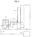
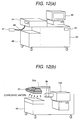
- Figs. 1 and 2 are illustration showing a construction of an embodiment of a monitoring system according to the present invention.
- the monitoring system is constructed with a gas sampling part 31 sampling a sample gas from a flue gas duct 30 of the incinerator 90, a monitor 32 detecting a measurement objective substance in a sample gas, and a combustion control device 69 for reflecting the result of detection to combustion control, and so forth.
- the monitor portion corresponds to a mass spectrometer employing the ion source according to the present invention.
- the gas sampling part 31 is constructed with an exhaust gas inlet pipe 63, a filter 64 and an exhaust gas outlet pipe 65 for feeding the sampled gas to the monitor 32 stably, without loss due to absorption or condensation of the measurement objective substance at the midway and in a constant flow rate, or to return to the flue gas duct 30. Therefore, the overall gas sampling part 31 is heated at a temperature in a range of about 100 °C to about 300 °C.
- the filter 64 is designed for avoiding penetration of dust or the like contained in the exhaust has of the incinerator into the monitor 32 and is provided in the vicinity of the flue gas duct 30 so as to reduce contamination of the exhaust gas inlet pipe 63, the monitor 32 and so forth as much as possible.
- the measurement objective substance in the fed sample gas is selectively and efficiently ionized, and mass spectrometric analysis of the generated ion is performed in the mass spectrometer 100 for continuously detecting the measurement objective substance.
- a relationship between an amount of preliminarily prepared substance and an ion current value (analytical curve), presenting amount of the objective substance cab be derived.
- analytical curve for example, in case of 2,3-dichlorophenol (molecular weight is 162 and mass number of monitored ion is 161), variation of ion strength in relation to concentration of the sample gas is measured to generate the analytical curve.
- a concentration data of the sample gas is estimated.
- Obtained data is further cleaned up to be stored together with concentration of the component and other parameter, and in conjunction therewith, to be output to a CRT or a printer.
- the obtained data is also fed to a combustion control unit 69 as data for controlling combustion in a garbage incineration plant via a signal line 68, for performing combustion control in the incinerator 90.
- Chlorobenzens as precusor of dioxin captures one electron to generate molecular ion M - .
- Chlorophenols provides a pseudo molecular ion (M-H) - .
- M - can be monitored.
- Dioxins provides (M-Cl) - , (M-Cl+O) - and so on in addition to molecular ion M - . By selectively detecting these characteristic peak, high sensitivity measurement with high selectivity can be performed.
- an ion trap mass spectrometer When an ion trap mass spectrometer is used, further higher selectivity can be obtained in comparison with the normal mass spectrometer. It is a MS/MS method, in which an energy is infused to the molecular ion captured within the ion trap mass spectrometer to cause collision with a buffer gas (He or the like) within the electrode to cause dissociation of the molecular ion.
- a buffer gas He or the like
- an ion releasing one or two chlorine atoms from molecular ion is monitored by the MS/MS method. For example, in case of 2, 4-dichlorophonol, upon ionizing using negative corona discharge, negative ion of (M-H) - (M: molecule, H: hydrogen) is generated.
- a negative ion released one chlorine atom is generated. Monitoring this negative ion may provide quite high selectivity. By determining quantity of negative ion amount released one chlorine atom from the peak intensity, amount of dichlorophenol in the exhaust gas can be estimated. When a plurality of kinds of molecular species to be measured are present, this measurement process may be repeated. In case of dioxins, COCl releasing process is monitored in addition to chlorine releasing process. Particularly, releasing of COCl is the process monitored only in dioxins. Conversely, when this process is monitored, it can be said that presence of TCDD or toxic dioxins is proven.
- dioxin and its associated compounds contained in the exhaust gas discharged during metal refining process or atmospheric air may also be monitored by the similar device and similar method.
- the monitoring device how much dioxins is contained in the exhaust gas of the incinerator or the like and how much fluctuation is caused can be known directly to achieve real time dioxin monitoring.
- the exhaust gas is discharged through various spaces of different temperatures and through various chemical processes caused in the exhaust gas. Even in each of such complicate processes, generation and decomposition of dioxin and so forth can be traced. Naturally, it is thus becomes possible to obtain information for modification and optimization of process condition for reducing dioxins.
- the device and method are effective in view of highly efficient ionization and expansion of life time.
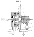
- Fig. 3 shows a construction of the ion source characterized by substantially opposing an introducing direction of the sample to the corona discharge region and withdrawing direction of the ion by the corona discharge in corona discharge generated at the tip end of the needle electrode by application of high voltage, and is a partially enlarged view of Fig. 1. Placement of the introducing direction of the sample to the corona discharge region and withdrawing direction of the ion by the corona discharge is significantly different point to the prior art.
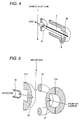
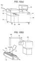
- Fig. 4 is an illustration showing a part of three-dimensional construction of the ion source.
- the sample introduced through a sample feed piping 1 is once introduced into the ion drift region 2.
- the ion drift region 2 is placed in substantially atmospheric pressure condition.
- a part of the sample introduced into the ion drift region 2 is introduced into a corona discharge region 3, and remaining is discharged out of the ion source through a sample output piping 4.
- the sample introduced into the corona discharge region 3 is introduced into a corona discharge region 6 generated at the tip end of the needle electrode 5 by applying a high voltage and ionized therein.
- the sample is introduced in a direction substantially opposing to flow of ion drifting toward the counter electrode 7 from the needle electrode 5.
- the generated ion is introduced into the ion drift region 2 through an opening portion 8 of the counter electrode 7.
- Ion introduced through the first ion sampling aperture 9 is introduced into the mass spectrometer 100 under vacuum condition through a second ion sampling aperture 11 and third ion sampling aperture 12.
- a region where the first ion sampling aperture 9, second ion sampling aperture 11 and third ion sampling aperture 12 are present, is a differential exhaust region for connecting the ion drift region 2 in substantially atmospheric pressure condition and the mass spectrometer under vacuum condition.
- an ion outlet piping 13 from the ion source and a flow controller 14 of ion source are provided in the corona discharge region 3.
- a sample flow rate passing through the ion outlet piping 13 from the ion source and a sample flow rate passing through the flow controller 14 of ion source can be determined by a capacity of intake pump 70, such as a diaphragm pump, and a conductance of piping provided downstream thereof.
- one of characteristics of the ion source of the present invention is that the intake pump 70 for introducing the sample into the corona discharge region is provided on the side of the ion outlet piping 13 from the ion source or the flow controller 14 of ion source instead of the sample feed piping 1. Namely, absorption or the like of the sample in the suction pump 70 which can be a problem in the case where the intake pump 70 is arranged on the side of the sample feed piping 1.
- the sample introduced through the sample feed piping 1 is once introduced into the ion drift region 2.
- a part of the sample introduced into the ion drift region 2 is introduced into the corona discharge region 3 (3a is a main body there of, 3b, 3c, 3d are the same), and remainder is discharge out of the ion source through the sample output piping 4.
- the flow rate of the sample passing through the ion outlet piping 13 from the ion source is about 10 to 2000 ml/min.
- 1/4 inches stainless electrolytic polishing piping or stainless piping coated with fused quartz on the inner peripheral surface may be used.
- the sample introduced into the corona discharge region 3 is introduced into the corona discharge region 6 generated at the tip end of the needle electrode 5 by application of the high voltage for ionization.
- positive ion about 1 to 6 kV is applied to the needle electrode 5
- negative ion about -1 to -6 kV is applied to the needle electrode 5.
- An electric field is formed for shifting the ion generated at the tip end of the needle electrode 5 in the direction of the counter electrode 7.
- a distance between the tip end of the needle electrode 5 and the counter electrode 7a (about 3 mm) is shorter than a distance between the tip end of the needle electrode 5 and the outer wall of the corona discharge region 3a located therearound (about 5mm).
- the sample is introduced in the direction substantially opposing to the flow of the ion drifted toward the counter electrode 7 (distance between the needle electrode 5 and the counter electrode 7 is about 3 mm) from the needle electrode 5.
- the ion generated in the corona discharge region at the tip end of the needle electrode 5 is introduced into the ion drift region 2 through the opening portion 8 (about 2 mm of diameter) of the counter electrode 7 (about 30 mm of diameter, 2 mm of thickness).
- the ion is drifted by the electric field to efficiently introduce into the first ion sampling aperture 9.
- a direction extending through the tip end of the needle electrode 5 and the center of the opening portion 8 for introducing the generated ion into the mass spectrometer and a direction to introduce the sample from the opening portion 8 to flow becomes 0° (opposing).
- the opening portion (ion outlet portion 12) from which the sample gas is discharged is located at a position inclined toward the tip end of the needle electrode.
- a voltage difference to be applied between the counter electrode 7 and the first ion sampling aperture 9 is variable depending upon the distance therebetween, but when the distance between the electrodes is about 1 to 10 mm, the voltage difference is about 10V to 2000V in absolute value. If the distance between the electrodes is too short, discharge becomes unstable, and if the distance between the electrode is too long, possibility of collision of the ion onto the partitioning wall is increased to reduce ion amount passing through the opening portion 8 to lower sensitivity.
- the voltage of the counter electrode 7 is set to be higher than that of the first ion sampling aperture 9. In practice, the voltage of the counter electrode 7 is about 100 to 2000V and the voltage of the first ion sampling aperture 9 is about 10 to 200V.
- the voltage to be applied to the counter electrode 7 is about -100 to -2000V and the voltage to be applied to the first ion sampling aperture 9 is about -10 to -200V.
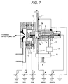
- the voltage to be applied to each electrode is shown in Fig. 7.
- the distance between the tip end of the needle electrode 5 and the counter electrode 7a is 3 mm and the distance between the counter electrode 7 and the first ion sampling aperture 9 is 7 mm. It is important that the sample feed piping 1, the corona discharge region 3 and so forth are grounded in viewpoint of prevention of electrical shock. While for the needle electrode 5 for corona discharge, a constant voltage power source is used as shown in Fig. 7, in addition, it is effective to use a constant current power source in viewpoint of maintaining the discharge current constant. On the other hand, it is important to control the flow rate of the sample introduced into the corona discharge region 6 for measuring the ion stably and in high precision.
- the ion outlet piping 13 from the ion source and the flow controller 14 of ion source are provided to perform flow rate control in a range of about 10 to 2000 ml/min.
- a cartridge heater or ceramic heater is used for heating in a range of about 50 to 400 °C. This temperature is variable depending upon the sample to be measured.
- reference numeral 71 denotes inner cylinder and 72, 73 denote insulators.
- mass spectrometer Upon analysis of the generated ion, various kinds of mass spectrometer can be used. The following discussion will be given for the case where ion accumulation type ion trapping mass spectrometer is used. Similar is true even in the case where quadrupole mass spectrometer performing mass separation using a high frequency electric field, magnetic sector type mass spectrometer using mass diffusion in the magnetic field and other mass spectrometers is used.
- the negative ion generated by the ion source used in the present invention is passes through the first ion sampling aperture 9 (about 0.3 mm diameter, about 0.5 mm length), the second ion sampling aperture 11 (about 0.3 mm diameter, about 0.5 mm length) and third ion sampling aperture 12 (about 0.3 mm diameter, about 0.5 mm length) provided in a flange type electrode 10 headed by a heater (not shown). These apertures are headed about 100 to 300 °C by the heater (not shown). Between the first ion sampling aperture 9, the second ion sampling aperture 11 and the third ion sampling aperture 12, a voltage can be applied to improve transmission coefficient.
- the differential discharge portion is normally discharged by roughing a vacuum pump, such as a rotary pump, a scroll pump, a mechanical booster pump or so forth. It is also possible to use a turbo molecule pump for discharging in this region.
- a vacuum pump such as a rotary pump, a scroll pump, a mechanical booster pump or so forth.
- turbo molecule pump for discharging in this region.
- FIG. 1 there is shown a case where the scroll pump 70 (discharge capacity about 900 l/min) is used in the discharge of the differential discharge portion, and the turbo molecule pump 30 (discharge capacity about 200 to 300 l/min) is used.
- a scroll pump 29 is used as a pump discharging back pressure side of the turbo molecule pump 30.
- a pressure between the second ion sampling aperture 11 and the third ion sampling aperture 12 is in a range of 0.1 to 10 Torr. It is also possible to form the differential discharge portion using two apertures of the first ion sampling aperture 9 and the third ion sampling aperture 12. In this case, in comparison with the foregoing case, since inflow gas amount is increased, some measure, such as increasing discharge speed of the vacuum pump or increasing distance between the apertures mat be required. On the other hand, in this case, it is important to apply voltage between both apertures.
- the generated ion is concentrated to a focusing lens 15.
- the focusing lens 15 Einzel lens normally consisted of three electrodes and so forth is used.
- the ion further passes through an electrode 16 with the slit.
- the focusing lens 15 the ion passing through the third ion sampling aperture 12 is focused to the slit portion. Not focused neutral particle or the like collides on this slit portion to be difficult to pass toward the mass spectrometer side.
- Ion passed through the electrode 16 with the slit is deflected and focused by the double cylindrical type lens 19 having an inner electrode 17 having a large number of opening portions and an outer electrode 18.
- the ion passed through the double cylindrical type lens 19 is introduced into the ion trapping mass spectrometer.
- An enlarged view of the ion trapping mass spectrometer which is constructed with a gate electrode 20, end cap electrodes 21a and 21b, a ring electrode 22, shielding electrodes 23a,23b, 23c and 23d, spacer rings 24a and 24b, an ion extract lens 25, is shown in Fig. 5.
- the gate electrode 20 serves for preventing introduction of the ion into the mass spectrometer from outside upon extracting the ion captured in the ion trapping mass spectrometer, out of the ion trapping mass spectrometer. As shown in Fig.
- the ion introduced into the ion trapping mass spectrometer through a ion sampling aperture 27 collides with a buffer gas, such helium or the like, also introduced into the ion trapping mass spectrometer to make the raceway track smaller. Then, by scanning the high frequency voltage applied between the end cap electrodes 21a and 21b and the ring electrode 22, ion is discharged out of the ion trapping mass spectrometer from the ion sampling aperture 28 per mass number and is detected by an ion detector 26 via the ion extract lens 25. The detected ion is amplified by an amplifier 42, and then transferred to a data processor 43.
- a buffer gas such helium or the like
- a pressure in the ion trapping mass spectrometer upon introduction of the buffer gas is about 10 -3 to 10 -4 Torr.
- the mass spectrometer 100 is controlled by a mass spectrometer control portion.
- One of merits of the ion trapping mass spectrometer has a property of capturing ion to expand an accumulation period even if concentration of the sample is lean. Accordingly, even when the sample concentration is low, high ratio condensation of the ion in the ion trapping mass spectrometer becomes possible to permit simplify pre-process, such as condensation of the sample or the like, in significant extent.
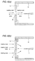
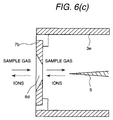
- Figs. 6(a), 6(b) and 6(c) show several shapes of the counter electrodes 7.
- the ion and the sample are introduced into the corona discharge region in manners as shown in Figs. 6(a), 6(b) and 6(c).
- Fig. 6(a) shows a ordinary disc-shaped counter electrode, in which the ion and the sample are introduced into the corona charge portion from the opening portion 8b.
- Fig. 6(b) shows the counter electrode having a plurality of opening portions 8c, in which the ion passes through the opening portion in the center portion and the sample passes through the opening portions in the circumferential portion.
- Fig. 6(c) shows the case where the peripheral wail of the opening portion 8d is tapered, by which the ion passing through the opening portion 8d can be easily accelerated.
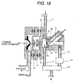
- Fig. 18 shows a construction, in which a direction of flow of the sample gas from the region of corona discharge and a direction of extracting the ion are different similarly to Fig. 3.
- the construction shown in Fig. 18 may be employed. Even in this case, by causing corona discharge between the tip end of the needle and the counter electrode 7a, similar effect as that achieved by the construction shown in Fig. 3 can be achieved.
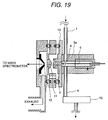
- Fig. 19 shows an example where the direction of flow of the sample from the corona discharge region 6 and the direction of extracting the ion are different but does not in opposition.
- the direction of flow of the sample is differentiated from the direction of the like connecting the tip end of the needle and the opening portion 9 in the extent of 90° .
- the ion and neutral molecule move in mutually perpendicular directions.
- Similar effect can be obtained by providing gradient differentiating moving direction other than opposite or perpendicular direction.
- Fig. 20 shows a construction, in which the ion source of Fig. 3 is extended.
- the gas is flown in the direction opposite to moving direction of the ion.
- the negative ion caused at the tip end of the needle can be sufficiently dispersed to maintain stable corona discharge for a long period by increasing flow velocity of the gas.
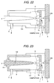
- Fig. 21 shows an embodiment, in which the needle electrode to be applied the high voltage is covered with an insulator.
- the ion source casing 8 is formed with a metal in view of machining, it is possible to cause discharge between the body of the needle electrode and the ion source casing. If discharge between the needle electrode and the counter electrode 7a fails, the amount of ion to pass through the aperture of the counter electrode is significantly reduced to lower sensitivity of the mass spectrometer.
- the needle electrode is covered by the insulator so as not to cause discharge on the peripheral surface of the body of the needle electrode as shown in Fig. 21, or the ion source casing is formed with insulator as shown in Fig. 22.
- the distance between the needle electrode 5 and the counter electrode 7a is about 3 mm, a distance between the side surface of the needle electrode and the ion source casing is more than or equal to 5 mm.
- Fig. 8 shows an alternative embodiment of Fig. 3.
- the shown embodiment is basically similar to Fig. 3.
- the like components will be identified like reference numerals and discussion for such common component will be omitted in order to avoid redundant disclosure for keeping the disclosure simple enough to facilitate clear understanding of the present invention.
- Fig. 3 shows the case where one ion drift region is provided. However, it is also possible to provide a plurality of ion drift regions.
- Fig. 8 shows the embodiment where second ion drift region 38 is provided in addition to the first ion drift portion 2, at a position adjacent to the latter.
- a reactant gas such as air
- O 2 - passes through the counter electrode 7a and the ion drift region 2.
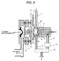
- Fig. 9 is an alternative embodiment of Fig. 3.
- the shown embodiment is basically the same as that of Fig. 3.
- the like components will be identified like reference numerals and discussion for such common component will be omitted in order to avoid redundant disclosure for keeping the disclosure simple enough to facilitate clear understanding of the present invention.
- a counter gas outlet electrode 72 is provided in front of the first ion sampling aperture 9.
- a distance between the first ion sampling aperture 9 and the counter gas outlet electrode 72 is 0.1 to 5 mm.
- an opening portion of about 2 mm diameter is formed to permit the air introduced through a counter flow gas inlet 71 to flow toward the counter electrode 7a. Comparing with the diameter (about 0.25 mm) of the first ion sampling aperture 9, the center of the counter gas outlet electrode 72 is greater.
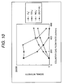
- One of important parameters of the ion source to be used in the present invention is a flow rate of the sample to be introduced into the corona discharge region 3 from the sample feed piping 1.
- the flow rate of the sample to be introduced into the corona discharge region 3 from the sample feed piping 1 is shown in Fig. 10.
- negative corona discharge current is 5 ⁇ A
- a distance between the counter electrode and the ion sampling aperture is 7 mm
- a voltage therebetween is 800V.
- a linear velocity of an intermediate (NO) generated in the corona discharge region is also increased. Accordingly, the fact that presence period of the intermediate in the corona discharge region is shortened, can be appreciated. As a result, generation of NO 3 - can be restricted to significantly increase ion strength of the dichlorophenol (corresponding to (DCP-H) - in the drawing).
- the merit of increasing of flow rate of the sample to be introduced into the corona discharge region is as set forth above.
- a CO 3 - signal intensity is lowered when the sample flow rate becomes greater than or equal to 300 ml/min.
- a signal intensity of O 2 - and (DCP-H) - become greater than either of those of NO 3 - and CO 3 - to achieve higher precision measurement.
- signal intensity can be controlled.
- Figs. 11(a), 11(b) and 11(c) show difference of mass spectra obtained when the conventional ion source is used and when the present invention is used using dichlorophenol (concentration 5 ⁇ g/Nm 3 ) in the air.
- negative corona discharge current is 5 ⁇ A
- a distance between the counter electrode and the ion sampling aperture is 7 mm and a voltage therebetween is 800V (voltage applied to the counter electrode is -850V and voltage applied to the ion sampling aperture is -50V).
- Figs. 11(b) and 11(c) show mass spectra obtained when the flow rates of the sample to be introduced into the corona discharge region are respectively 200 and 500 ml/mm, respectively.
- Figs. 12 and 13 show construction of an explosive detector 33 for detecting explosive or drug in a public facility, such as an airport. Upon detection of explosive, such as nitro compound, a system using the mass spectrometer having the ion source according to the present invention is effective. In Fig. 14, mass spectra of TNT and RDX as nitro compounds are shown, it can be appreciated that M - or (M+NO 2 ) - is monitored.
- Fig. 12(a) shows the case where a suction probe for sucking the sample gas through sample gas inlet 44, a inlet piping 46 and inlet opening 47.
- Fig. 12(b) shows the case where a duct 53 connected to a sample gas feed piping 52 and the corona discharge region 3.
- the object for inspection 54 is moved at a position below the sample gas feed piping 52 by a conveyer 57 containing in a inspection scanner 55, a vapor of the explosive is sucked with respect to the inspection object 54.
- the ion generated through the sample gas feed piping 52 and the corona discharge region 3 is detected by the mass spectrometer 100.
- it is effective to heat the inspection object at a temperature higher than the room temperature (about 40 to 60 °C) by a heater 57.
- the moved inspection object 54 is held on a support 56 after inspection.
- the explosive as typified by nitro compound easily becomes negative ion by negative corona discharge similarly to the organic chlorine-based chemical compound. Therefore, the shown system is effective for detecting explosive. Normally, in a display device 45 in the explosive detector 33, variation in time of the generated ion strength (mass chromatograph) and so forth are displayed. When explosive, such as TNT is present in the vapor to be analyzed, the ion strength corresponding to the molecular amount of TNT is increased. When abnormality is not detected by this explosive detector 33, the luggage may pass through. If abnormality is detected, detailed re-inspection is performed.
- the explosive in case of a plastic bomb, if the explosive is present in the luggage as a thick mass, it can be detected by an X-ray inspection device. However, if the plastic bomb is in a thin sheet form, most of X-ray may pass through to possibly overlooked by the X-ray inspection device and thus is difficult to detect. At this time, by using the explosive detector, the explosive can be detected as far as the vapor leaks within the luggage or out of the luggage. Thus, probability of detection of the explosive can be significantly increased in comparison with the X-ray inspection device.
- the explosive detector having the ion source according to the present invention is more advantageous than the X-ray inspection device.
- the ion source according to the present invention is further applicable as the ion source to be used in a liquid chromatograph mass spectrometer.
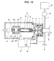
- a construction of the liquid chromatograph mass spectrometer is shown in Fig. 16. Namely, an eluate from the liquids chromatograph 36 is vaporized by an appropriate vaporizer (comprising a conduit 59 for spraying by heating or by gas). Then, the vapor is introduced into the ion source of the present invention to ionization, and the generated ion is detected by the mass spectrometer.
- an appropriate vaporizer comprising a conduit 59 for spraying by heating or by gas.
- the vapor is introduced into the ion source of the present invention to ionization, and the generated ion is detected by the mass spectrometer.
- heating type vaporizer 37 is employed.
- a metal block is welled to the conduit 59.
- the metal block 60 can be controlled a temperature by a thermocouple 62 and a cartridge heater 61.
- the eluate from the liquid chromatograph 36 is converted into a fine liquid droplet in the terminal at the end of the conduit 59.
- the present invention since the direction of flow of the sample relative to the corona discharge region and the direction to extract the ion by corona discharge are different. Therefore, a presence period of the intermediate in the corona discharge region can be shortened. Therefore, the ion of the objective sample can be efficiently generated. Also, according to the present invention, high selectivity and high sensitivity measurement of the ion of the sample becomes possible. In addition, even when deposition is deposited at the tip end of the needle electrode, discharge can be maintained stably for a long period, for example 2 months or more.
Priority Applications (1)
| Application Number | Priority Date | Filing Date | Title |
|---|---|---|---|
| EP10009000A EP2296167B1 (de) | 1999-09-20 | 2000-09-15 | Ionenquelle, Massenspektrometer, Detektor und Überwachungssystem |
Applications Claiming Priority (4)
| Application Number | Priority Date | Filing Date | Title |
|---|---|---|---|
| JP26604499A JP4054493B2 (ja) | 1999-09-20 | 1999-09-20 | イオン源 |
| JP26604499 | 1999-09-20 | ||
| JP2000247937 | 2000-08-10 | ||
| JP2000247937A JP4126150B2 (ja) | 2000-08-10 | 2000-08-10 | 質量分析装置 |
Publications (3)
| Publication Number | Publication Date |
|---|---|
| EP1093151A2 true EP1093151A2 (de) | 2001-04-18 |
| EP1093151A3 EP1093151A3 (de) | 2006-05-03 |
| EP1093151B1 EP1093151B1 (de) | 2010-09-01 |
Family
ID=26547283
Family Applications (2)
| Application Number | Title | Priority Date | Filing Date |
|---|---|---|---|
| EP00120100A Expired - Lifetime EP1093151B1 (de) | 1999-09-20 | 2000-09-15 | Ionenquelle, Massenspektrometer, Massenspektrometrie und Überwachungssystem |
| EP10009000A Expired - Lifetime EP2296167B1 (de) | 1999-09-20 | 2000-09-15 | Ionenquelle, Massenspektrometer, Detektor und Überwachungssystem |
Family Applications After (1)
| Application Number | Title | Priority Date | Filing Date |
|---|---|---|---|
| EP10009000A Expired - Lifetime EP2296167B1 (de) | 1999-09-20 | 2000-09-15 | Ionenquelle, Massenspektrometer, Detektor und Überwachungssystem |
Country Status (4)
| Country | Link |
|---|---|
| US (2) | US6686592B1 (de) |
| EP (2) | EP1093151B1 (de) |
| DE (1) | DE60044892D1 (de) |
| IL (1) | IL138540A0 (de) |
Cited By (7)
| Publication number | Priority date | Publication date | Assignee | Title |
|---|---|---|---|---|
| EP1275956A2 (de) * | 2001-07-05 | 2003-01-15 | Hitachi, Ltd. | Sicherheitssystem und Methode für ein Sicherheitsservicegeschäft |
| EP1376095A1 (de) * | 2002-06-24 | 2004-01-02 | Hitachi, Ltd. | System zur Feststellung von gefährlichem Stoff |
| EP2387791A1 (de) * | 2009-01-14 | 2011-11-23 | Sociedad Europea De Analisis Diferencial De Movilidad S.L. | Verbesster ionisator für dampfanalyse mittels entkopplung des ionisationsbereichs vom analysator |
| WO2013144679A3 (en) * | 2011-11-16 | 2014-12-11 | Owlstone Limited | Corona ionization device and method |
| GB2521027B (en) * | 2013-09-20 | 2017-11-01 | Micromass Ltd | Ion inlet assembly |
| US10026600B2 (en) | 2011-11-16 | 2018-07-17 | Owlstone Medical Limited | Corona ionization apparatus and method |
| EP3047507B1 (de) * | 2013-09-20 | 2019-06-26 | Micromass UK Limited | Schnittstelle für ionenquelle und vakuumgehäuse |
Families Citing this family (22)
| Publication number | Priority date | Publication date | Assignee | Title |
|---|---|---|---|---|
| EP1093151B1 (de) * | 1999-09-20 | 2010-09-01 | Hitachi, Ltd. | Ionenquelle, Massenspektrometer, Massenspektrometrie und Überwachungssystem |
| JP3701182B2 (ja) * | 2000-08-24 | 2005-09-28 | 株式会社日立製作所 | 出入管理方法及び出入管理システム |
| AU2003297655B2 (en) * | 2002-12-02 | 2007-09-20 | Griffin Analytical Technologies, Inc. | Processes for designing mass separators and ion traps, methods for producing mass separators and ion traps. mass spectrometers, ion traps, and methods for analysing samples |
| JP4337584B2 (ja) * | 2004-03-10 | 2009-09-30 | 株式会社日立製作所 | 質量分析装置及びイオン源 |
| WO2006002027A2 (en) | 2004-06-15 | 2006-01-05 | Griffin Analytical Technologies, Inc. | Portable mass spectrometer configured to perform multidimensional mass analysis |
| JP4492267B2 (ja) * | 2004-09-16 | 2010-06-30 | 株式会社日立製作所 | 質量分析装置 |
| GB2439261B (en) | 2005-04-25 | 2011-02-23 | Griffin Analytical Technologies Llc | Analytical apparatuses and methods |
| US8469700B2 (en) * | 2005-09-29 | 2013-06-25 | Rosemount Inc. | Fouling and corrosion detector for burner tips in fired equipment |
| JP4507281B2 (ja) | 2006-03-30 | 2010-07-21 | 富士フイルム株式会社 | 画像表示装置、撮像装置および画像表示方法 |
| US7804076B2 (en) * | 2006-05-10 | 2010-09-28 | Taiwan Semiconductor Manufacturing Co., Ltd | Insulator for high current ion implanters |
| US7992424B1 (en) | 2006-09-14 | 2011-08-09 | Griffin Analytical Technologies, L.L.C. | Analytical instrumentation and sample analysis methods |
| US8017919B2 (en) * | 2007-12-28 | 2011-09-13 | Newaire, Inc. | Multi-electrode negative ion generator |
| GB2472638B (en) * | 2009-08-14 | 2014-03-19 | Edwards Ltd | Vacuum system |
| JP5041495B2 (ja) * | 2010-11-01 | 2012-10-03 | シャープ株式会社 | イオン発生装置 |
| EP2660590A1 (de) * | 2010-12-27 | 2013-11-06 | Shiseido Co., Ltd. | Massenspektrometrisches verfahren, massenspektrometer und massenspektrometriesystem |
| JP5992715B2 (ja) * | 2012-04-05 | 2016-09-14 | シャープ株式会社 | イオン発生装置 |
| WO2014084015A1 (ja) | 2012-11-29 | 2014-06-05 | 株式会社日立ハイテクノロジーズ | ハイブリッドイオン源、質量分析計及びイオンモビリティ装置 |
| EP4181170A1 (de) | 2013-09-20 | 2023-05-17 | Micromass UK Limited | Ioneneinlassanordnung |
| US10060838B2 (en) | 2015-04-09 | 2018-08-28 | Ut-Battelle, Llc | Capture probe |
| US9632066B2 (en) | 2015-04-09 | 2017-04-25 | Ut-Battelle, Llc | Open port sampling interface |
| CN106480436B (zh) * | 2015-08-31 | 2021-02-19 | 中国科学院大连化学物理研究所 | 一种镀层电喷针的制备方法 |
| US11125657B2 (en) * | 2018-01-30 | 2021-09-21 | Ut-Battelle, Llc | Sampling probe |
Citations (4)
| Publication number | Priority date | Publication date | Assignee | Title |
|---|---|---|---|---|
| US4531056A (en) * | 1983-04-20 | 1985-07-23 | Yale University | Method and apparatus for the mass spectrometric analysis of solutions |
| JPH02135655A (ja) * | 1988-11-16 | 1990-05-24 | Hitachi Ltd | 大気圧イオン化質量分析計 |
| US5485016A (en) * | 1993-04-26 | 1996-01-16 | Hitachi, Ltd. | Atmospheric pressure ionization mass spectrometer |
| JPH11218521A (ja) * | 1998-02-02 | 1999-08-10 | Mitsubishi Heavy Ind Ltd | ダイオキシン分析装置及びダイオキシン計測システム |
Family Cites Families (18)
| Publication number | Priority date | Publication date | Assignee | Title |
|---|---|---|---|---|
| US4023398A (en) | 1975-03-03 | 1977-05-17 | John Barry French | Apparatus for analyzing trace components |
| JPS5725944B2 (de) | 1975-05-12 | 1982-06-01 | ||
| JPS59230244A (ja) | 1984-05-17 | 1984-12-24 | ザ・ガバ−ニング・カウンセル・オブ・ザ・ユニバ−シテイ・オブ・トロント | 痕跡成分を真空室内で分析する方法 |
| JPH07118295B2 (ja) * | 1985-10-30 | 1995-12-18 | 株式会社日立製作所 | 質量分析計 |
| JP2756581B2 (ja) | 1989-05-15 | 1998-05-25 | 日本真空技術株式会社 | 液体クロマトグラフィ質量分析計用イオン源 |
| JP2872746B2 (ja) | 1990-05-02 | 1999-03-24 | 賢三 平岡 | エレクトロスプレー式質量分析装置 |
| US5218203A (en) * | 1991-03-22 | 1993-06-08 | Georgia Tech Research Corporation | Ion source and sample introduction method and apparatus using two stage ionization for producing sample gas ions |
| US5331218A (en) | 1992-07-13 | 1994-07-19 | Allegro Microsystems, Inc. | Switched-capacitor notch filter with programmable notch width and depth |
| JP3324810B2 (ja) | 1993-01-19 | 2002-09-17 | ブラザー工業株式会社 | ミシン |
| JP3367719B2 (ja) | 1993-09-20 | 2003-01-20 | 株式会社日立製作所 | 質量分析計および静電レンズ |
| JP2774774B2 (ja) * | 1994-06-14 | 1998-07-09 | 東京都 | 高速液体クロマトグラフィーと質量分析計を組み合わせた定量分析装置、およびその試料イオン化用コロナ放電電極針 |
| JPH08261989A (ja) | 1995-03-24 | 1996-10-11 | Osaka Oxygen Ind Ltd | シラン系ガス中のシロキサンの計測方法 |
| US6189461B1 (en) * | 1996-12-06 | 2001-02-20 | Nkk Corporation | Burning apparatus and method for restricting the occurrence of dioxins |
| US6032513A (en) * | 1997-06-30 | 2000-03-07 | Texas Instruments Incorporated | Apparatus and method for measuring contaminants in semiconductor processing chemicals |
| JP3819146B2 (ja) | 1998-04-20 | 2006-09-06 | 株式会社日立製作所 | モニタ装置 |
| JP3904322B2 (ja) * | 1998-04-20 | 2007-04-11 | 株式会社日立製作所 | 分析装置 |
| JP2000028579A (ja) | 1998-07-08 | 2000-01-28 | Hitachi Ltd | 試料ガス採取装置及び危険物探知装置 |
| EP1093151B1 (de) * | 1999-09-20 | 2010-09-01 | Hitachi, Ltd. | Ionenquelle, Massenspektrometer, Massenspektrometrie und Überwachungssystem |
-
2000
- 2000-09-15 EP EP00120100A patent/EP1093151B1/de not_active Expired - Lifetime
- 2000-09-15 EP EP10009000A patent/EP2296167B1/de not_active Expired - Lifetime
- 2000-09-15 DE DE60044892T patent/DE60044892D1/de not_active Expired - Lifetime
- 2000-09-18 IL IL13854000A patent/IL138540A0/xx unknown
- 2000-09-18 US US09/663,796 patent/US6686592B1/en not_active Expired - Lifetime
-
2003
- 2003-09-02 US US10/651,997 patent/US6838664B2/en not_active Expired - Fee Related
Patent Citations (4)
| Publication number | Priority date | Publication date | Assignee | Title |
|---|---|---|---|---|
| US4531056A (en) * | 1983-04-20 | 1985-07-23 | Yale University | Method and apparatus for the mass spectrometric analysis of solutions |
| JPH02135655A (ja) * | 1988-11-16 | 1990-05-24 | Hitachi Ltd | 大気圧イオン化質量分析計 |
| US5485016A (en) * | 1993-04-26 | 1996-01-16 | Hitachi, Ltd. | Atmospheric pressure ionization mass spectrometer |
| JPH11218521A (ja) * | 1998-02-02 | 1999-08-10 | Mitsubishi Heavy Ind Ltd | ダイオキシン分析装置及びダイオキシン計測システム |
Non-Patent Citations (2)
| Title |
|---|
| GRAVENDEEL B ET AL: "Clustered negative ions in atmospheric negative corona discharges in the Trichel regime" JOURNAL OF PHYSICS. B. ATOMIC AND MOLECULAR PHYSICS, INSTITUTE OF PHYSICS, LONDON, GB, vol. 20, 1987, pages 6337-6361, XP002221637 ISSN: 0022-3700 * |
| PATENT ABSTRACTS OF JAPAN vol. 014, no. 371 (E-0963), 10 August 1990 (1990-08-10) & JP 02 135655 A (HITACHI LTD), 24 May 1990 (1990-05-24) * |
Cited By (11)
| Publication number | Priority date | Publication date | Assignee | Title |
|---|---|---|---|---|
| EP1275956A2 (de) * | 2001-07-05 | 2003-01-15 | Hitachi, Ltd. | Sicherheitssystem und Methode für ein Sicherheitsservicegeschäft |
| EP1275956A3 (de) * | 2001-07-05 | 2004-02-18 | Hitachi, Ltd. | Sicherheitssystem und Methode für ein Sicherheitsservicegeschäft |
| US7091870B2 (en) | 2001-07-05 | 2006-08-15 | Hitachi, Ltd. | Security system and method of security service business |
| EP1376095A1 (de) * | 2002-06-24 | 2004-01-02 | Hitachi, Ltd. | System zur Feststellung von gefährlichem Stoff |
| US6806450B2 (en) | 2002-06-24 | 2004-10-19 | Hitachi, Ltd. | Hazardous material detection system |
| US6940067B2 (en) | 2002-06-24 | 2005-09-06 | Hitachi, Ltd. | Hazardous material detection system |
| EP2387791A1 (de) * | 2009-01-14 | 2011-11-23 | Sociedad Europea De Analisis Diferencial De Movilidad S.L. | Verbesster ionisator für dampfanalyse mittels entkopplung des ionisationsbereichs vom analysator |
| WO2013144679A3 (en) * | 2011-11-16 | 2014-12-11 | Owlstone Limited | Corona ionization device and method |
| US10026600B2 (en) | 2011-11-16 | 2018-07-17 | Owlstone Medical Limited | Corona ionization apparatus and method |
| GB2521027B (en) * | 2013-09-20 | 2017-11-01 | Micromass Ltd | Ion inlet assembly |
| EP3047507B1 (de) * | 2013-09-20 | 2019-06-26 | Micromass UK Limited | Schnittstelle für ionenquelle und vakuumgehäuse |
Also Published As
| Publication number | Publication date |
|---|---|
| EP2296167A1 (de) | 2011-03-16 |
| US6838664B2 (en) | 2005-01-04 |
| US6686592B1 (en) | 2004-02-03 |
| EP2296167B1 (de) | 2012-11-07 |
| DE60044892D1 (de) | 2010-10-14 |
| EP1093151B1 (de) | 2010-09-01 |
| IL138540A0 (en) | 2001-10-31 |
| US20040036020A1 (en) | 2004-02-26 |
| EP1093151A3 (de) | 2006-05-03 |
Similar Documents
| Publication | Publication Date | Title |
|---|---|---|
| EP1093151B1 (de) | Ionenquelle, Massenspektrometer, Massenspektrometrie und Überwachungssystem | |
| US4849628A (en) | Atmospheric sampling glow discharge ionization source | |
| JP3660279B2 (ja) | 試料イオン化装置及び質量分析計 | |
| US8372183B2 (en) | Detection system for airborne particles | |
| JP3904322B2 (ja) | 分析装置 | |
| US7164124B2 (en) | Mass spectrometric apparatus and ion source | |
| US6677582B2 (en) | Ion source and mass spectrometer | |
| US7332345B2 (en) | Chemical sensor system | |
| JP4054493B2 (ja) | イオン源 | |
| US20100132561A1 (en) | Electrostatic charging and collection | |
| US6943343B2 (en) | Chemical agent detection apparatus and method | |
| JP2001351569A (ja) | ガス測定用オンラインモニター装置 | |
| JP3907796B2 (ja) | 電子捕獲型検出装置及び電子捕獲型検出方法 | |
| EP0292974A2 (de) | Entladungsionisierungsquelle zum Analysieren der Atmosphäre | |
| JP2006058318A (ja) | 試料ガス採取装置及び危険物探知装置 | |
| JP4062341B2 (ja) | イオン化質量分析計,分析方法およびそれを用いた計測システム | |
| JP4291398B2 (ja) | 質量分析装置および危険物探知装置 | |
| JP4303264B2 (ja) | 分析装置 | |
| JP4197676B2 (ja) | モニタリングシステム | |
| JP3819146B2 (ja) | モニタ装置 |
Legal Events
| Date | Code | Title | Description |
|---|---|---|---|
| PUAI | Public reference made under article 153(3) epc to a published international application that has entered the european phase |
Free format text: ORIGINAL CODE: 0009012 |
|
| AK | Designated contracting states |
Kind code of ref document: A2 Designated state(s): AT BE CH CY DE DK ES FI FR GB GR IE IT LI LU MC NL PT SE |
|
| AX | Request for extension of the european patent |
Free format text: AL;LT;LV;MK;RO;SI |
|
| PUAL | Search report despatched |
Free format text: ORIGINAL CODE: 0009013 |
|
| AK | Designated contracting states |
Kind code of ref document: A3 Designated state(s): AT BE CH CY DE DK ES FI FR GB GR IE IT LI LU MC NL PT SE |
|
| AX | Request for extension of the european patent |
Extension state: AL LT LV MK RO SI |
|
| RIC1 | Information provided on ipc code assigned before grant |
Ipc: H01J 49/04 20060101AFI20010213BHEP Ipc: G01N 27/68 20060101ALI20060315BHEP |
|
| 17P | Request for examination filed |
Effective date: 20060331 |
|
| 17Q | First examination report despatched |
Effective date: 20060728 |
|
| AKX | Designation fees paid |
Designated state(s): DE FR GB |
|
| 17Q | First examination report despatched |
Effective date: 20060728 |
|
| RIC1 | Information provided on ipc code assigned before grant |
Ipc: G01N 27/68 20060101ALI20091211BHEP Ipc: H01J 49/04 20060101ALI20091211BHEP Ipc: H01J 49/16 20060101AFI20091211BHEP |
|
| RTI1 | Title (correction) |
Free format text: ION SOURCE, MASS SPECTROMETER, MASS SPECTROMETRY, AND MONITORING SYSTEM |
|
| GRAP | Despatch of communication of intention to grant a patent |
Free format text: ORIGINAL CODE: EPIDOSNIGR1 |
|
| GRAS | Grant fee paid |
Free format text: ORIGINAL CODE: EPIDOSNIGR3 |
|
| GRAA | (expected) grant |
Free format text: ORIGINAL CODE: 0009210 |
|
| AK | Designated contracting states |
Kind code of ref document: B1 Designated state(s): DE FR GB |
|
| REG | Reference to a national code |
Ref country code: GB Ref legal event code: FG4D |
|
| REF | Corresponds to: |
Ref document number: 60044892 Country of ref document: DE Date of ref document: 20101014 Kind code of ref document: P |
|
| PLBE | No opposition filed within time limit |
Free format text: ORIGINAL CODE: 0009261 |
|
| STAA | Information on the status of an ep patent application or granted ep patent |
Free format text: STATUS: NO OPPOSITION FILED WITHIN TIME LIMIT |
|
| 26N | No opposition filed |
Effective date: 20110606 |
|
| REG | Reference to a national code |
Ref country code: DE Ref legal event code: R097 Ref document number: 60044892 Country of ref document: DE Effective date: 20110606 |
|
| REG | Reference to a national code |
Ref country code: FR Ref legal event code: PLFP Year of fee payment: 16 |
|
| REG | Reference to a national code |
Ref country code: FR Ref legal event code: PLFP Year of fee payment: 17 |
|
| REG | Reference to a national code |
Ref country code: FR Ref legal event code: PLFP Year of fee payment: 18 |
|
| REG | Reference to a national code |
Ref country code: FR Ref legal event code: PLFP Year of fee payment: 19 |
|
| PGFP | Annual fee paid to national office [announced via postgrant information from national office to epo] |
Ref country code: FR Payment date: 20190815 Year of fee payment: 20 Ref country code: DE Payment date: 20190903 Year of fee payment: 20 |
|
| PGFP | Annual fee paid to national office [announced via postgrant information from national office to epo] |
Ref country code: GB Payment date: 20190912 Year of fee payment: 20 |
|
| REG | Reference to a national code |
Ref country code: DE Ref legal event code: R071 Ref document number: 60044892 Country of ref document: DE |
|
| REG | Reference to a national code |
Ref country code: GB Ref legal event code: PE20 Expiry date: 20200914 |
|
| PG25 | Lapsed in a contracting state [announced via postgrant information from national office to epo] |
Ref country code: GB Free format text: LAPSE BECAUSE OF EXPIRATION OF PROTECTION Effective date: 20200914 |