BACKGROUND OF THE INVENTION
The present invention relates to an ion source, a mass
spectrometer and mass spectrometry employing the ion source, and
monitoring system employing the same or a monitor employing the ion
source.
Conventionally, as a method for detecting a minor component in a
gas or a liquid in high sensitivity, it has been performed a method for
detecting an ion generated by ionization of a measuring object in high
sensitivity by means of a mass spectrometer.
There are various methods for ionizing a sample. One of various
sample ionizing method is an atmospheric pressure chemical ionization
employing corona discharge. As disclosed in Japanese Patent
Application Laid-Open No. 51-8996 (1976), this is a method to introduce
a sample in a corona discharge region generated at the tip end of a needle
electrode by applying a high voltage for ionizing the sample. At this time,
in addition to the case where the sample is directly ionized by corona
discharge (primary ionization), the sample is also ionized by ion molecule
reaction (secondary ionization) to result in high efficiency ionization of
sample molecule.
On the other hand, as disclosed in Japanese Patent Application
Laid-Open No. 6 -310091 (1994), among ionization method by corona
discharge, there has been proposed a method for ionizing without
directly introducing a sample gas into a corona discharge region.
Namely, the proposed method is to use a primary ion generated in a
separately provided corona discharge region and to efficiently perform
secondary ionization of the sample molecule not passing through the
corona discharge region by ion molecule reaction. This method is
particularly effectively for objective sample, such as silane gas, which
cannot be directly ionized using corona discharge for extreme
contamination of ion source by discharge product.
Furthermore, there is a method disclosed in U. S. Patent No.
4,023,398 to French et al. In the shown example, there is disclosed a
technology, in which a curtain gas is blown between the corona
discharge region and an aperture for introducing ion into vacuum in
order to prevent introduction of a carrier gas into a mass spectrometric
portion under vacuum condition for transporting the sample. Thereby,
discharge efficiency can be improved when a vacuum discharge system
such as a cryopump is used.
Furthermore, Japanese Patent Application Laid-Open No. 3-179252
(1991) discloses a gas flow direction. In this method, a liquid
sample flows through a hollow needle electrode, a fine droplet of the
liquid sample ionized at the tip end of the needle is efficiently vaporized
by a dry gas flowing in opposition. On the other hand, dispersion of
ionized sample is suppressed to improve maintenance efficiency.
However, Japanese Patent Application Laid-Open No. 3-179252 (1991)
does not disclose a problem in stability of discharge and solution of the
problem.
In the prior art disclosed in the above-identified Japanese Patent
Application Laid-Open No. 51-8996 (1976) and Japanese Patent
Application Laid-Open No. 3-179252 (1991), when the concentration of a
measuring sample is low (for example, upon measurement of minor
component in the air or upon measuring minor component in the liquid),
intensity of ion of the component presenting in greater amount in
comparison with the ion of the measuring sample, or ion originated from
a component presenting in large amount (for example, ion or the like
generated by ion molecule reaction), becomes extremely high.
Accordingly, when a sensitivity of a detector is set adapting to ion of the
measuring sample in fine amount, ion of the component presenting in
large amount or the ion originated from the component presenting in
large amount may reach the detector to cause a large current to flow at a
burst to damage the detector to gradually degrade an amplification factor
of a current.
On the other hand, when molecule corresponding to component
presenting in large amount or molecule corresponding to ion originated
from the component presenting in large amount can be ionized easier
than molecule of the objective sample, generation efficiency of the ion of
the objective sample is lowered to result in lowering of sensitivity.
Furthermore, in case of ion trap type mass spectrometer performing
mass spectrometric analysis of the accumulated ion by scanning a high
frequency voltage after accumulating the ion, ion less than or equal to a
mass number corresponding to amplitude of the high frequency voltage
to be applied may directly reach the detector after passing through an ion
trap mass spectrometric portion. Accordingly, when ion is present in
large amount, the detector is damaged to gradually degrade amplification
of current.
On the other hand, Japanese Patent Application Laid-Open No.
3-179252 (1991) is related to the ion source for analyzing the liquid
sample but has no disclosure for analysis of gas.
Further, the method disclosed in U. S. Patent No. 4,023,398,
while introduction of the carrier gas into vacuum by using the curtain
gas, the obtained mass spectrum is nothing different from the prior art.
Therefore, the problem similar to the prior art can be encountered.
Furthermore, in the prior art set forth above, the components in
the gas to be measured may be deposited on the tip end of the needle to
make corona discharge unstable to cause difficulty in continuous
measurement for a long period. In case of the method disclosed in
Japanese Patent Application Laid-Open No. 6-210091 (1994), nothing
has been discussed with respect to continuous operation over a long
period in the extent of one month.
SUMMARY OF THE INVENTION
Accordingly, it is an object of the present invention to provide an
ion source using a corona discharge for efficiently generating ion of a
sample and a device employing the same.
Another object of the present invention is to provide an ion source
which can maintain stable discharge for a long period, and a device
employing the same.
1) Means for Improving Ion Generation Efficiency
At first, as means for improving ion generation efficiency. in
corona discharge generated at the tip end of needle electrode by applying
high voltage, a direction connecting a needle electrode and a partitioning
wall having an opening for taking the generated ion into a mass
spectrometric portion, namely a direction along which the ion is drawn
from a discharge region , and a direction of flow of a sample gas are
differentiated. Thereby, generation efficiency of ion of the objective
sample can be significantly improved.
By taking the construction as set forth above, the following effect
is caused. For example, primary ion molecular reaction in the case
where chlorophenols in dry air is monitored using negative corona
discharge becomes as follow:
O2 + e- → O2 -
(negative corona discharge)
O2 + N2 → 2NO
(negative corona discharge)
O2 - + NO → NO3 -
O2 - + (CP) → (CP-H)- + HO2
Here, (CP-H)- represents a negative ion removed proton from CP. As can
be appreciated from the foregoing expression, basically, O2 - generated by
negative corona discharge intervenes reaction. By reaction of N2 and O2
under corona discharge, NO3 - is easily generated via the NO as
intermediate. Thus, ion having high strength can be monitored. Since
NO3 - has high acidity, it will not react with CP. Accordingly, what is
monitored when concentration of N2 is quite high in comparison with CP,
is mostly NO3 -, and little (CP-H)- is monitored.
Among such reaction process, when reaction of O2 - + NO → NO3 - can
be restricted, reduction of O2 - can be suppressed. By this, O2 - + CP
→ (CP-H)- + HO2 is progressed. Thus, NO3 - possibly generated in large
amount can be significantly reduced. Accordingly, generation amount
of the objective (CP-H) can be increased. For restricting generation of
NO3 -, it is important not to form overlapping regions of O2 - and NO. One
approach for this is to differentiate the direction of ion movement and the
direction of the intermediate to flow by the electric field to make the
present period of the intermediate in the corona discharge region
extremely short. Particularly, when the foregoing two directions are
opposite, significant effect can be achieved. At this time, the reaction
process set forth above, the presence of the intermediate NO can be
ignored. Accordingly, the foregoing reaction is substantially:
O2 + e- → O2-
(negative corona discharge)
O2 - + CP → (CP-H)- + HO2
This mode of reaction is quite desirable in view point of monitoring of
(CP-H)- at high precision.
2) Means for Maintaining Discharge Period for Long Period
The present invention provides a mass spectrometer and a mass
spectrometry. In the mass spectrometer having an ion source
performing ionization of a sample by generating a corona discharge at a
tip end of a needle electrode by applying a high voltage to said needle
electrode, the ion source is constructed to form an angle between a
direction extend ion across the needle electrode and the opening portion
for taking the generated ion into the mass spectrometric portion, namely
a direction along which the ion is drawn from the discharge region, and a
direction of flow of the sample gas greater than or equal 90° (in other
view, a direction extending across the tip end of the needle electrode and
the first opening for feeding the ion to the mass spectrometric portion
and a direction extending across the center of the first opening portion
and the tip end of the needle electrode form an angle less than or equal to
90° .
With the construction set forth above, in addition to improvement
of ion generation efficiency of the measurement objective substance,
stable discharge can be maintained for a long period. One of the
reasons is set out hereinafter.
The reason why stable discharge can be maintained for a long
period will be discussed in terms of negative corona discharge.
The reason why stable discharge cannot be maintained for a long
period when gas flow does not present in the discharge region. Then
components in the gas is deposited on the tip end of the needle electrode
to make curvature greater to cause instability of discharge. In such
case, fluctuation is caused in the current value of discharge to make
ionization unstable and the ion strength measured by the mass
spectrometer also fluctuates. In order to make analysis with high
reliability, maintenance to frequently change the needle electrode and
sharpening the tip end of the needle electrode is required.
When negative corona discharge is used, an electron is
discharged from the tip end of the needle electrode applied negative high
pressure to collide with neutral molecule in the gas to cause ionization.
The ionizing region is quite close to the tip end (within 1 mm). The
negative ion generated is moved toward the counter electrode by the
electrical field between the needle electrode and the counter electrode.
The phenomenon that the radius of curvature at the tip end of the needle
electrode becomes greater, results in fluctuation of the discharge current
value for the following reason.
By repeating the foregoing 1) to 4), the flow of the discharge
current flows. When the radius of curvature of the tip end of the needle
electrode is small, even if the field intensity is weaken, the discharge
current may not be lowered to permit continuous discharge. However, if
the radius of curvature of the tip end of the needle electrode, due to effect
of space charge of the negative ion, the field intensity is lowered to result
in lowering of the discharge current. When the voltage is lowered in
order to prevent lowering of the discharge current, the discharge mode
may transit from the corona discharge to spark discharge to make
discharge mode unstable to not suited for analysis.
When flow of the gas is caused in the ionizing region, the negative
ion possibly cause space charge is dispersed to restrict lowering of the
field intensity of the tip end of the needle electrode.
Accordingly, by generating the gas flow in the tip end region of the
needle electrode, to maintain stable discharge even when the radius of
curvature of the tip end of the needle electrode becomes large for
deposition in certain extent.
When the sample gas is flown from the route side of the needle the
region actively cause ionization in the vicinity of the tip end of the needle
electrode falls into the disturbed condition to cause difficulty in
efficiently disperse the space charge.
On the other hand, by providing a function for monitoring the
discharge current value and the amplitude of the current value becomes
greater than or equal to a certain value, an alarm for exchanging the
needle , the maintenance timing of the needle electrode can be known
properly.
BRIEF DESCRIPTION OF THE DRAWINGS
The present invention will be understood more fully from the
detailed description given hereinafter and from the accompanying
drawings of the preferred embodiment of the present invention, which,
however, should not be taken to be limitative to the invention, but are for
explanation and understanding only.
Fig. 1 is an illustration showing an example intended to perform
dioxin monitoring by means of a mass spectrometer having an ion source
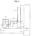
according to the present invention; Fig. 2 is an illustration showing an example intended to perform
dioxin monitoring by means of a mass spectrometer having an ion source
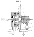
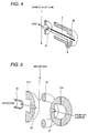
according to the present invention; Fig. 3 is a detailed illustration of the ion source; Fig. 4 is an explanatory illustration of the ion source according to
the present invention; Fig. 5 is an illustration showing a construction of an ion trap
portion of a mass spectrometer; Fig. 6(a) is an illustration showing an opposing relationship
between an ion and a sample; Fig. 6(b) is an illustration showing an opposing relationship
between an ion and a sample; Fig. 6(c) is an illustration showing an opposing relationship
between an ion and a sample; Fig. 7 is an illustration showing an example of voltage application
in the ion source; Fig. 8 is an illustration showing a construction of an alternative
embodiment of Fig. 3; Fig. 9 is an illustration showing a construction of an alternative
embodiment of Fig. 3; Fig. 10 is a characteristic chart; Fig. 11(a) is an illustration showing an example of mass spectrum
obtained by the ion source of the present invention; Fig. 11(b) is an illustration showing an example of mass spectrum
obtained by the ion source of the present invention; Fig. 11(c) is an illustration showing an example of mass spectrum
obtained by the ion source of the present invention; Fig. 12(a) is a constructional illustration showing one
embodiment of explosive detection having the ion source according to the
present invention; Fig. 12(b) is a constructional illustration showing one
embodiment of explosive detection having the ion source according to the
present invention; Fig. 12(c) is a constructional illustration showing one
embodiment of explosive detection having the ion source according to the
present invention; Fig. 13(a) is a constructional illustration showing one
embodiment of explosive detection having the ion source according to the
present invention; Fig. 13(b) is a constructional illustration showing one
embodiment of explosive detection having the ion source according to the
present invention; Fig. 14 is an illustration showing an example of mass spectrum to
be obtained from the ion source of the present invention; Fig. 15 is an illustration showing a detection algorithm in
explosive detection; Fig. 16 is a sectional illustration showing one example of a mass
spectrometer with the ion source according to the present invention; Fig. 17 is a constructional illustration of an example of a
vaporizer to be employed in the liquid chromatographic mass
spectrometer; Fig. 18 is an illustration showing a construction of an alternative
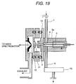
embodiment of Fig. 3; Fig. 19 is an illustration showing a construction of an alternative
embodiment of Fig. 3; Fig. 20 is a constructional illustration extended the ion source
portion of Fig. 3; Fig. 21 is an illustration showing a construction of an alternative
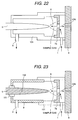
embodiment of Fig. 20; Fig. 22 is an illustration showing a construction of an alternative
embodiment of Fig. 20; and Fig. 23 is an illustration showing a construction of an alternative
embodiment of Fig. 20.
DESCRIPTION OF THE PREFERRED EMBODIMENTS
The present invention will be discussed hereinafter in detail in
terms of the preferred embodiment of the present invention with
reference to the accompanying drawings. In the following description,
numerous specific details are set forth in order to provide a thorough
understanding of the present invention. It will be obvious, however, to
those skilled in the art that the present invention may be practiced
without these specific details. In other instance, well-known structure
are not shown in detail in order to avoid unnecessary obscurity of the
present invention.
Application to Dioxin Monitor
An ion source according to the present invention will be
discussed in terms of application to a dioxin monitor.
A mass spectrometer employing an ion source according to the
present invention is directly connected to an incinerator or the like and
can perform continuous monitoring components of an exhaust has from
the incinerator or the like. Particularly, it becomes possible to
significantly reduce generation amount of dioxins by measuring dioxins
or chlorobenzens, chlorophenols, hydrocarbons as precursor discharged
from the incinerator and by controlling combustion condition of the
incinerator depending upon the result of measurement.
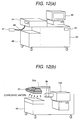
Figs. 1 and 2 are illustration showing a construction of an
embodiment of a monitoring system according to the present invention.
In this case, the monitoring system is constructed with a gas sampling
part 31 sampling a sample gas from a flue gas duct 30 of the incinerator
90, a monitor 32 detecting a measurement objective substance in a
sample gas, and a combustion control device 69 for reflecting the result
of detection to combustion control, and so forth. The monitor portion
corresponds to a mass spectrometer employing the ion source according
to the present invention.
The gas sampling part 31 is constructed with an exhaust gas inlet
pipe 63, a filter 64 and an exhaust gas outlet pipe 65 for feeding the
sampled gas to the monitor 32 stably, without loss due to absorption or
condensation of the measurement objective substance at the midway
and in a constant flow rate, or to return to the flue gas duct 30.
Therefore, the overall gas sampling part 31 is heated at a temperature in
a range of about 100 °C to about 300 °C. The filter 64 is designed for
avoiding penetration of dust or the like contained in the exhaust has of
the incinerator into the monitor 32 and is provided in the vicinity of the
flue gas duct 30 so as to reduce contamination of the exhaust gas inlet
pipe 63, the monitor 32 and so forth as much as possible. In the
monitor 32, the measurement objective substance in the fed sample gas
is selectively and efficiently ionized, and mass spectrometric analysis of
the generated ion is performed in the mass spectrometer 100 for
continuously detecting the measurement objective substance.
From an ion current value in a mass number originated from the
measurement objective substance, a relationship between an amount of
preliminarily prepared substance and an ion current value (analytical
curve), presenting amount of the objective substance cab be derived.
For example, in case of 2,3-dichlorophenol (molecular weight is 162 and
mass number of monitored ion is 161), variation of ion strength in
relation to concentration of the sample gas is measured to generate the
analytical curve. On the basis of this, from the monitored ion strength,
a concentration data of the sample gas is estimated. Obtained data is
further cleaned up to be stored together with concentration of the
component and other parameter, and in conjunction therewith, to be
output to a CRT or a printer. On the other hand, the obtained data is
also fed to a combustion control unit 69 as data for controlling
combustion in a garbage incineration plant via a signal line 68, for
performing combustion control in the incinerator 90.
Chlorobenzens as precusor of dioxin captures one electron to
generate molecular ion M-. Chlorophenols provides a pseudo molecular
ion (M-H)-. In case of trichlorophenol containing three chlorine atoms,
M- can be monitored. Dioxins provides (M-Cl)-, (M-Cl+O)- and so on in
addition to molecular ion M-. By selectively detecting these characteristic
peak, high sensitivity measurement with high selectivity can be
performed.
For estimating dioxin concentration from concentration of
chlorobenzens, chlorophenols, preliminarily derived correlation is used.
Since correlation is slightly different depending upon system, type and so
forth of the incinerator or the like, it is preferable to preliminarily obtain
data of correlation per incinerator, to which the monitor is installed in
order to estimate the dioxin concentration at higher precision.
When an ion trap mass spectrometer is used, further higher
selectivity can be obtained in comparison with the normal mass
spectrometer. It is a MS/MS method, in which an energy is infused to
the molecular ion captured within the ion trap mass spectrometer to
cause collision with a buffer gas (He or the like) within the electrode to
cause dissociation of the molecular ion. In case of organic chlorine-based
chemical compound, an ion releasing one or two chlorine atoms
from molecular ion is monitored by the MS/MS method. For example,
in case of 2, 4-dichlorophonol, upon ionizing using negative corona
discharge, negative ion of (M-H)- (M: molecule, H: hydrogen) is generated.
Dissociating this negative ion by MS/MS method, a negative ion released
one chlorine atom is generated. Monitoring this negative ion may
provide quite high selectivity. By determining quantity of negative ion
amount released one chlorine atom from the peak intensity, amount of
dichlorophenol in the exhaust gas can be estimated. When a plurality of
kinds of molecular species to be measured are present, this
measurement process may be repeated. In case of dioxins, COCl
releasing process is monitored in addition to chlorine releasing process.
Particularly, releasing of COCl is the process monitored only in dioxins.
Conversely, when this process is monitored, it can be said that presence
of TCDD or toxic dioxins is proven. In case of the organic chlorine-based
chemical compound, when number of chlorine is increased,
chemically stable substance is formed. Therefore, in case of dioxins
having large number of chlorine, dioxin precusor or the like, it is effective
to dissociate foreign matter overlapping the measuring objective ion
instead of the measuring objective ion, to measure the measuring
objective ion in high sensitivity.
In the foregoing example, discussion has been given mainly for
the case where the atmospheric pressure chemical ionization method of
negative ionizing mode. Various components are contained in the
exhaust gas. Concerning hydrocarbon type compound of aromatic
compound represented by benzene or the like, measurement of
atmospheric pressure chemical ionization method in positive ionization
mode becomes possible. For example, in case of benzene or
monochlorobenzene, ion species of M+ is generated by the atmospheric
pressure chemical ionization method in positive ionization mode.
Accordingly, in actual sample gas measurement, by alternately
measuring positive and negative ionization modes, it is possible to
increase information amount in the sample gas.
Here, discussion has been given for monitoring of dioxin and
compounds associated therewith in the exhaust gas mainly discharged
from the garbage processing facility. However, dioxin and its associated
compounds contained in the exhaust gas discharged during metal
refining process or atmospheric air may also be monitored by the similar
device and similar method. By the monitoring device, how much
dioxins is contained in the exhaust gas of the incinerator or the like and
how much fluctuation is caused can be known directly to achieve real
time dioxin monitoring. Furthermore, from initiation of combustion in
the incinerator to be discharged from an exhaust flue to the atmosphere,
the exhaust gas is discharged through various spaces of different
temperatures and through various chemical processes caused in the
exhaust gas. Even in each of such complicate processes, generation
and decomposition of dioxin and so forth can be traced. Naturally, it is
thus becomes possible to obtain information for modification and
optimization of process condition for reducing dioxins. Also, upon
analyzing fine component in other gas, the device and method are
effective in view of highly efficient ionization and expansion of life time.
Fig. 3 shows a construction of the ion source characterized by
substantially opposing an introducing direction of the sample to the
corona discharge region and withdrawing direction of the ion by the
corona discharge in corona discharge generated at the tip end of the
needle electrode by application of high voltage, and is a partially enlarged
view of Fig. 1. Placement of the introducing direction of the sample to
the corona discharge region and withdrawing direction of the ion by the
corona discharge is significantly different point to the prior art. Fig. 4 is
an illustration showing a part of three-dimensional construction of the
ion source.
The sample introduced through a sample feed piping 1 is once
introduced into the ion drift region 2. The ion drift region 2 is placed in
substantially atmospheric pressure condition. A part of the sample
introduced into the ion drift region 2 is introduced into a corona
discharge region 3, and remaining is discharged out of the ion source
through a sample output piping 4. The sample introduced into the
corona discharge region 3 is introduced into a corona discharge region 6
generated at the tip end of the needle electrode 5 by applying a high
voltage and ionized therein. At this time, the sample is introduced in a
direction substantially opposing to flow of ion drifting toward the counter
electrode 7 from the needle electrode 5. The generated ion is introduced
into the ion drift region 2 through an opening portion 8 of the counter
electrode 7. At this time, by applying a voltage between the counter
electrode 7 and the first ion sampling aperture 9, ion is drifted to be
efficiently introduced into the first ion sampling aperture 9. Ion
introduced through the first ion sampling aperture 9 is introduced into
the mass spectrometer 100 under vacuum condition through a second
ion sampling aperture 11 and third ion sampling aperture 12. A region
where the first ion sampling aperture 9, second ion sampling aperture 11
and third ion sampling aperture 12 are present, is a differential exhaust
region for connecting the ion drift region 2 in substantially atmospheric
pressure condition and the mass spectrometer under vacuum condition.
On the other hand, it is important to control flow rate of the sample to be
introduced into a corona discharge region 6 for measuring the ion stably
and in high precision. Therefore, an ion outlet piping 13 from the ion
source and a flow controller 14 of ion source are provided in the corona
discharge region 3. On the other hand, in view of prevention of
absorption of the sample in the ion drift region 2 and the corona
discharge region 3, it is important to heat these regions. A sample flow
rate passing through the ion outlet piping 13 from the ion source and a
sample flow rate passing through the flow controller 14 of ion source can
be determined by a capacity of intake pump 70, such as a diaphragm
pump, and a conductance of piping provided downstream thereof. As
set forth above, one of characteristics of the ion source of the present
invention is that the intake pump 70 for introducing the sample into the
corona discharge region is provided on the side of the ion outlet piping 13
from the ion source or the flow controller 14 of ion source instead of the
sample feed piping 1. Namely, absorption or the like of the sample in
the suction pump 70 which can be a problem in the case where the
intake pump 70 is arranged on the side of the sample feed piping 1.
Hereinafter, further detailed embodiment will be discussed.
The sample introduced through the sample feed piping 1 is once
introduced into the ion drift region 2. A part of the sample introduced
into the ion drift region 2 is introduced into the corona discharge region 3
(3a is a main body there of, 3b, 3c, 3d are the same), and remainder is
discharge out of the ion source through the sample output piping 4. For
the sample introduced through the sample feed piping 1, the flow rate of
the sample passing through the ion outlet piping 13 from the ion source
is about 10 to 2000 ml/min. It should be noted that, as the sample feed
piping 1 and the sample output piping 4, 1/4 inches stainless electrolytic
polishing piping or stainless piping coated with fused quartz on the inner
peripheral surface may be used. The sample introduced into the corona
discharge region 3 is introduced into the corona discharge region 6
generated at the tip end of the needle electrode 5 by application of the
high voltage for ionization. When positive ion is generated, about 1 to 6
kV is applied to the needle electrode 5, and when negative ion is
generated, about -1 to -6 kV is applied to the needle electrode 5. At this
time, it is important to cause discharge between the tip end of the needle
electrode 5 and the counter electrode 7a instead of between the tip end of
the needle electrode 5 and an outer wall of the corona discharge region
3a located therearound. An electric field is formed for shifting the ion
generated at the tip end of the needle electrode 5 in the direction of the
counter electrode 7. Accordingly, a distance between the tip end of the
needle electrode 5 and the counter electrode 7a (about 3 mm) is shorter
than a distance between the tip end of the needle electrode 5 and the
outer wall of the corona discharge region 3a located therearound (about
5mm). At this time, the sample is introduced in the direction
substantially opposing to the flow of the ion drifted toward the counter
electrode 7 (distance between the needle electrode 5 and the counter
electrode 7 is about 3 mm) from the needle electrode 5. The ion
generated in the corona discharge region at the tip end of the needle
electrode 5 is introduced into the ion drift region 2 through the opening
portion 8 (about 2 mm of diameter) of the counter electrode 7 (about 30
mm of diameter, 2 mm of thickness). At this time, by applying a voltage
between the counter electrode 7 and the first ion sampling aperture 9,
the ion is drifted by the electric field to efficiently introduce into the first
ion sampling aperture 9. In this case, a direction extending through the
tip end of the needle electrode 5 and the center of the opening portion 8
for introducing the generated ion into the mass spectrometer and a
direction to introduce the sample from the opening portion 8 to flow
becomes 0° (opposing). On the other hand, the opening portion (ion
outlet portion 12) from which the sample gas is discharged, is located at
a position inclined toward the tip end of the needle electrode.
A voltage difference to be applied between the counter electrode 7
and the first ion sampling aperture 9 is variable depending upon the
distance therebetween, but when the distance between the electrodes is
about 1 to 10 mm, the voltage difference is about 10V to 2000V in
absolute value. If the distance between the electrodes is too short,
discharge becomes unstable, and if the distance between the electrode is
too long, possibility of collision of the ion onto the partitioning wall is
increased to reduce ion amount passing through the opening portion 8 to
lower sensitivity. Upon measurement of the positive ion, the voltage of
the counter electrode 7 is set to be higher than that of the first ion
sampling aperture 9. In practice, the voltage of the counter electrode 7
is about 100 to 2000V and the voltage of the first ion sampling aperture 9
is about 10 to 200V. Conversely, upon measurement of the negative ion,
opposite to the case of positive ion measurement, the voltage to be
applied to the counter electrode 7 is about -100 to -2000V and the
voltage to be applied to the first ion sampling aperture 9 is about -10 to
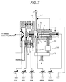
-200V. When the negative ion is measured, in the ion source of the
present invention, an example of the voltage to be applied to each
electrode is shown in Fig. 7.
At this time, the distance between the tip end of the needle
electrode 5 and the counter electrode 7a is 3 mm and the distance
between the counter electrode 7 and the first ion sampling aperture 9 is 7
mm. It is important that the sample feed piping 1, the corona discharge
region 3 and so forth are grounded in viewpoint of prevention of electrical
shock. While for the needle electrode 5 for corona discharge, a constant
voltage power source is used as shown in Fig. 7, in addition, it is effective
to use a constant current power source in viewpoint of maintaining the
discharge current constant. On the other hand, it is important to
control the flow rate of the sample introduced into the corona discharge
region 6 for measuring the ion stably and in high precision. Therefore,
in the corona discharge region 3, the ion outlet piping 13 from the ion
source and the flow controller 14 of ion source are provided to perform
flow rate control in a range of about 10 to 2000 ml/min. In view of
prevention of absorption of sample in the ion drift region 2 and the
corona discharge region 3, it is important to uniformly heat these regions.
For this purpose, a cartridge heater or ceramic heater is used for heating
in a range of about 50 to 400 °C. This temperature is variable
depending upon the sample to be measured.
It should be noted that the reference numeral 71 denotes inner
cylinder and 72, 73 denote insulators.
Detailed discussion will be given hereinafter with respect to the
mass spectrometer and so forth. Upon analysis of the generated ion,
various kinds of mass spectrometer can be used. The following
discussion will be given for the case where ion accumulation type ion
trapping mass spectrometer is used. Similar is true even in the case
where quadrupole mass spectrometer performing mass separation using
a high frequency electric field, magnetic sector type mass spectrometer
using mass diffusion in the magnetic field and other mass spectrometers
is used.
The negative ion generated by the ion source used in the present
invention is passes through the first ion sampling aperture 9 (about 0.3
mm diameter, about 0.5 mm length), the second ion sampling aperture
11 (about 0.3 mm diameter, about 0.5 mm length) and third ion
sampling aperture 12 (about 0.3 mm diameter, about 0.5 mm length)
provided in a flange type electrode 10 headed by a heater (not shown).
These apertures are headed about 100 to 300 °C by the heater (not
shown). Between the first ion sampling aperture 9, the second ion
sampling aperture 11 and the third ion sampling aperture 12, a voltage
can be applied to improve transmission coefficient. Also, due to
collision of the residual molecule, cleavage of ionized cluster generated
by adiabatic expansion is caused to generate ion of the sample molecule.
The differential discharge portion is normally discharged by roughing a
vacuum pump, such as a rotary pump, a scroll pump, a mechanical
booster pump or so forth. It is also possible to use a turbo molecule
pump for discharging in this region. In Fig. 1, there is shown a case
where the scroll pump 70 (discharge capacity about 900 l/min) is used in
the discharge of the differential discharge portion, and the turbo
molecule pump 30 (discharge capacity about 200 to 300 l/min) is used.
As a pump discharging back pressure side of the turbo molecule pump
30, a scroll pump 29 is used. A pressure between the second ion
sampling aperture 11 and the third ion sampling aperture 12 is in a
range of 0.1 to 10 Torr. It is also possible to form the differential
discharge portion using two apertures of the first ion sampling aperture
9 and the third ion sampling aperture 12. In this case, in comparison
with the foregoing case, since inflow gas amount is increased, some
measure, such as increasing discharge speed of the vacuum pump or
increasing distance between the apertures mat be required. On the
other hand, in this case, it is important to apply voltage between both
apertures.
After passing the third ion sampling aperture 12, the generated
ion is concentrated to a focusing lens 15. As the focusing lens 15,
Einzel lens normally consisted of three electrodes and so forth is used.
The ion further passes through an electrode 16 with the slit. By the
focusing lens 15, the ion passing through the third ion sampling
aperture 12 is focused to the slit portion. Not focused neutral particle or
the like collides on this slit portion to be difficult to pass toward the mass
spectrometer side. Ion passed through the electrode 16 with the slit is
deflected and focused by the double cylindrical type lens 19 having an
inner electrode 17 having a large number of opening portions and an
outer electrode 18. In the double cylindrical type lens 19, deflection and
focusing is performed using the electric field of the outer electrode 18
exsudated from the opening portion of the inner electrode. The detail
has been disclosed in Japanese Patent Application Laid-Open No. Heisei
7-85834 (corresponding to U. S. Patent No. 5,481,107 to Ose et al. The
disclosure of Japanese Patent Application Laid-Open No. 7-85834
(1995) will be herein incorporated by reference.
The ion passed through the double cylindrical type lens 19 is
introduced into the ion trapping mass spectrometer. An enlarged view
of the ion trapping mass spectrometer which is constructed with a gate
electrode 20, end cap electrodes 21a and 21b, a ring electrode 22,
shielding electrodes 23a,23b, 23c and 23d, spacer rings 24a and 24b, an
ion extract lens 25, is shown in Fig. 5. The gate electrode 20 serves for
preventing introduction of the ion into the mass spectrometer from
outside upon extracting the ion captured in the ion trapping mass
spectrometer, out of the ion trapping mass spectrometer. As shown in
Fig. 5, the ion introduced into the ion trapping mass spectrometer
through a ion sampling aperture 27 collides with a buffer gas, such
helium or the like, also introduced into the ion trapping mass
spectrometer to make the raceway track smaller. Then, by scanning the
high frequency voltage applied between the end cap electrodes 21a and
21b and the ring electrode 22, ion is discharged out of the ion trapping
mass spectrometer from the ion sampling aperture 28 per mass number
and is detected by an ion detector 26 via the ion extract lens 25. The
detected ion is amplified by an amplifier 42, and then transferred to a
data processor 43. A pressure in the ion trapping mass spectrometer
upon introduction of the buffer gas, is about 10-3 to 10-4 Torr. The mass
spectrometer 100 is controlled by a mass spectrometer control portion.
One of merits of the ion trapping mass spectrometer has a property of
capturing ion to expand an accumulation period even if concentration of
the sample is lean. Accordingly, even when the sample concentration is
low, high ratio condensation of the ion in the ion trapping mass
spectrometer becomes possible to permit simplify pre-process, such as
condensation of the sample or the like, in significant extent.
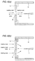
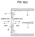
Figs. 6(a), 6(b) and 6(c) show several shapes of the counter
electrodes 7. The ion and the sample are introduced into the corona
discharge region in manners as shown in Figs. 6(a), 6(b) and 6(c). Fig.
6(a) shows a ordinary disc-shaped counter electrode, in which the ion
and the sample are introduced into the corona charge portion from the
opening portion 8b. Fig. 6(b) shows the counter electrode having a
plurality of opening portions 8c, in which the ion passes through the
opening portion in the center portion and the sample passes through the
opening portions in the circumferential portion. Fig. 6(c) shows the case
where the peripheral wail of the opening portion 8d is tapered, by which
the ion passing through the opening portion 8d can be easily accelerated.
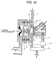
Fig. 18 shows a construction, in which a direction of flow of the
sample gas from the region of corona discharge and a direction of
extracting the ion are different similarly to Fig. 3. However, when an
orientation of the needle is to be modified, the construction shown in Fig.
18 may be employed. Even in this case, by causing corona discharge
between the tip end of the needle and the counter electrode 7a, similar
effect as that achieved by the construction shown in Fig. 3 can be
achieved.
Fig. 19 shows an example where the direction of flow of the
sample from the corona discharge region 6 and the direction of extracting
the ion are different but does not in opposition. In case of Fig. 19, the
direction of flow of the sample is differentiated from the direction of the
like connecting the tip end of the needle and the opening portion 9 in the
extent of 90° . In this case, the ion and neutral molecule move in
mutually perpendicular directions. However, by increasing flow velocity
of the sample gas, similar effect to that achieved by the construction
shown in Fig. 3 can be achieved. Similar effect can be obtained by
providing gradient differentiating moving direction other than opposite or
perpendicular direction.
Fig. 20 shows a construction, in which the ion source of Fig. 3 is
extended. By forming gas flow at the tip end of the needle, stable corona
discharge can be maintained for a long period. In this case, with taking
ion generation efficiency into account, the gas is flown in the direction
opposite to moving direction of the ion. As shown in Fig. 19, even when
the direction of gas flow at the tip end of the needle is not opposite
direction to the moving direction of the ion, the negative ion caused at the
tip end of the needle can be sufficiently dispersed to maintain stable
corona discharge for a long period by increasing flow velocity of the gas.
Fig. 21 shows an embodiment, in which the needle electrode to be
applied the high voltage is covered with an insulator. When the ion
source casing 8 is formed with a metal in view of machining, it is possible
to cause discharge between the body of the needle electrode and the ion
source casing. If discharge between the needle electrode and the
counter electrode 7a fails, the amount of ion to pass through the
aperture of the counter electrode is significantly reduced to lower
sensitivity of the mass spectrometer. In order to prevent this, the needle
electrode is covered by the insulator so as not to cause discharge on the
peripheral surface of the body of the needle electrode as shown in Fig. 21,
or the ion source casing is formed with insulator as shown in Fig. 22. In
the alternative, it is also effective to provide sufficient distance between
the ion source casing 3 and the needle electrode 5. As a rough standard,
it is preferred that when the distance between the needle electrode 5
and the counter electrode 7a is about 3 mm, a distance between the side
surface of the needle electrode and the ion source casing is more than or
equal to 5 mm.
On the other hand, as shown in Fig. 23, when the side surface of
the needle electrode is coated by gold plating or hard chrome plating
except for the tip end of the needle, discharge is hardly caused on the
body of the needle electrode, and normal discharge between the needle
electrode and the counter electrode can be easily caused to maintain
stable discharge for a long period. Further, when corrosive gas, such as
hydrogen chloride, is used, the needle electrode formed as set forth above
is effective in view point of corrosion resistance.
Fig. 8 shows an alternative embodiment of Fig. 3. The shown
embodiment is basically similar to Fig. 3. In the following disclosure,
the like components will be identified like reference numerals and
discussion for such common component will be omitted in order to avoid
redundant disclosure for keeping the disclosure simple enough to
facilitate clear understanding of the present invention.
Fig. 3 shows the case where one ion drift region is provided.
However, it is also possible to provide a plurality of ion drift regions. Fig.
8 shows the embodiment where second ion drift region 38 is provided in
addition to the first ion drift portion 2, at a position adjacent to the latter.
One example of the operation is as follow. The sample gas is introduced
through the sample feed piping 1b and is discharged from the sample
outlet piping 4b. At this time, a reactant gas, such as air, is introduced
through a reactant gas inlet piping 39. When a part of the reactant gas
is introduced into the corona discharge region, on the basis of principle
discussed in the foregoing embodiment (1), mainly O2 - passes through
the counter electrode 7a and the ion drift region 2. To the sample gas
introduced through the sample feed piping 1b, for example, air
containing chlorophenol or the like, O2 - is driven through the second
counter electrode 66, the ion of the chlorophenol is generated. Electric
fields are provided between the counter electrode 7 and the second
counter electrode 66 and between the second counter electrode 66 and
the first ion sampling aperture 9. An inter-electrode distance between
the counter electrode 7 and the second counter electrode 66 and the
distance between the second counter electrode 66 and the first ion
sampling aperture 9 are both about 1 to 10 mm. In measurement of the
negative ion, when about -10V is applied to the first ion sampling
aperture 9, about -1 kV, -2 kV are applied to the counter electrode 7 and
the second counter electrode 66, respectively. These voltages controls a
retention period of O2 - in the ion drift region 2, namely reaction time. In
the case where reaction of O2 - in the ion drift region 2 is problem, the
retention period may be shortened by set voltage higher. The ion is
introduced into the mass spectrometer through the first ion sampling
aperture 9. Significant merit of construction set forth above is that
when the sample gas is the exhaust gas of the incinerator, the exhaust
gas is not introduced into the corona discharge region directly. Threrby,
contamination of the needle electrode can be prevented to permit use for
a long period.
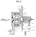
Fig. 9 is an alternative embodiment of Fig. 3. The shown
embodiment is basically the same as that of Fig. 3. In the following
disclosure, the like components will be identified like reference numerals
and discussion for such common component will be omitted in order to
avoid redundant disclosure for keeping the disclosure simple enough to
facilitate clear understanding of the present invention.
In case of Fig. 3, ion is drifted between the counter electrode 7a
and the first ion sampling aperture 9. In contrast to this, in addition to
the construction set forth above, a counter gas outlet electrode 72 is
provided in front of the first ion sampling aperture 9. A distance
between the first ion sampling aperture 9 and the counter gas outlet
electrode 72 is 0.1 to 5 mm. At the center of the counter gas outlet
electrode 72, an opening portion of about 2 mm diameter is formed to
permit the air introduced through a counter flow gas inlet 71 to flow
toward the counter electrode 7a. Comparing with the diameter (about
0.25 mm) of the first ion sampling aperture 9, the center of the counter
gas outlet electrode 72 is greater. At this time, between the counter gas
outlet electrode 72 and the first ion sampling aperture 9, the ion is
drifted toward the first ion sampling aperture 9 by the electric field.
When the distance between the first ion sampling aperture 9 and the
counter gas outlet electrode 72 is 0.5 mm, a voltage difference between
the electrodes is about 10 to 500V. With taking such construction, a
particle containing liquid droplet, dust hardly enter into the first ion
sampling aperture 9 to efficiently introduce only ion.
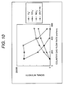
One of important parameters of the ion source to be used in the
present invention is a flow rate of the sample to be introduced into the
corona discharge region 3 from the sample feed piping 1. By setting and
controlling the flow rate to be greater than or equal to a certain value, the
ion of the sample can be stably measured in high sensitivity. A
relationship between the flow rate of the sample to be introduced into the
corona discharge region 3 from the sample feed piping 1 and ion strength
of dichlorophenol or the like is shown in Fig. 10. At this time, negative
corona discharge current is 5 µA, a distance between the counter
electrode and the ion sampling aperture is 7 mm and a voltage
therebetween is 800V. As can be appreciated from the drawing, by
setting the flow rate to be introduced into the corona discharge region
from the sample feed piping to be greater than or equal to about 100
ml/min, ion strength of the dichlorophenol (corresponding to (DCP-H)-)
in the drawing) can be significantly increased. On the other hand,
strengths of NO3 - (ion corresponding to mass number 62), CO3 - or N2O2 - (ion
corresponding to mass number 60) are reduced according to
increasing of the flow rate. In the ion source according to the present
invention, usefulness of setting the flow rate of the sample to be
introduced into the corona discharge region, greater than or equal to a
certain value (for example, 100 ml/min) can be appreciated herefrom.
According to increase of the flow rate of the sample to be
introduced into the corona discharge region, a linear velocity of an
intermediate (NO) generated in the corona discharge region is also
increased. Accordingly, the fact that presence period of the
intermediate in the corona discharge region is shortened, can be
appreciated. As a result, generation of NO3 - can be restricted to
significantly increase ion strength of the dichlorophenol (corresponding
to (DCP-H)- in the drawing). The merit of increasing of flow rate of the
sample to be introduced into the corona discharge region is as set forth
above.
A CO3 - signal intensity is lowered when the sample flow rate
becomes greater than or equal to 300 ml/min. When the flow rate
becomes greater than or equal to 400 ml/min, a signal intensity of O2 - and
(DCP-H)- become greater than either of those of NO3 - and CO3 - to
achieve higher precision measurement. As set forth above, by
controlling counter gas flow, signal intensity can be controlled.
By employing the ion source of the present invention, fine
component in the air can be detected in high sensitivity. Figs. 11(a),
11(b) and 11(c) show difference of mass spectra obtained when the
conventional ion source is used and when the present invention is used
using dichlorophenol (concentration 5 µg/Nm3) in the air. At this time,
negative corona discharge current is 5 µA, a distance between the
counter electrode and the ion sampling aperture is 7 mm and a voltage
therebetween is 800V (voltage applied to the counter electrode is -850V
and voltage applied to the ion sampling aperture is -50V). In the
conventional ion source, while extremely strong NO3 - is monitored, only
little amount of negative ion (CP-H)- originated from chlorophenol can be
monitored (Fig. 11(a)). In contrast to this, in the ion source of the
present invention, it can be appreciated that in addition to relative
strength of (CP-H)- relative to NO3 -, absolute sensitivity is improved
significantly (Figs. 11(b) and 11(c)).
Here, Figs. 11(b) and 11(c) show mass spectra obtained when the
flow rates of the sample to be introduced into the corona discharge region
are respectively 200 and 500 ml/mm, respectively.
Application to Explosive Detector
Next, discussion will be given for application of the ion source
according to the present invention to an explosive detector.
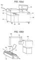
Figs. 12 and 13 show construction of an explosive detector 33 for
detecting explosive or drug in a public facility, such as an airport. Upon
detection of explosive, such as nitro compound, a system using the mass
spectrometer having the ion source according to the present invention is
effective. In Fig. 14, mass spectra of TNT and RDX as nitro compounds
are shown, it can be appreciated that M- or (M+NO2)- is monitored.
Upon detection of the explosive, presence of explosive is checked
by using a probe or duct sucking a sample gas, for sucking, ionizing and
detecting the vapor of explosive leaking from luggage 35 or cargo in off-line
or on-line. Fig. 12(a) shows the case where a suction probe for
sucking the sample gas through sample gas inlet 44, a inlet piping 46
and inlet opening 47. On the other hand, Fig. 12(b) shows the case
where a duct 53 connected to a sample gas feed piping 52 and the corona
discharge region 3. On the other hand, it is also possible to take holding
pass or passport as object for inspection 54, as shown in Fig. 13. At this
time, the object for inspection 54 is moved at a position below the sample
gas feed piping 52 by a conveyer 57 containing in a inspection scanner
55, a vapor of the explosive is sucked with respect to the inspection
object 54. The ion generated through the sample gas feed piping 52 and
the corona discharge region 3 is detected by the mass spectrometer 100.
At this time, it is effective to heat the inspection object at a temperature
higher than the room temperature (about 40 to 60 °C) by a heater 57.
The moved inspection object 54 is held on a support 56 after inspection.
The explosive as typified by nitro compound, easily becomes
negative ion by negative corona discharge similarly to the organic
chlorine-based chemical compound. Therefore, the shown system is
effective for detecting explosive. Normally, in a display device 45 in the
explosive detector 33, variation in time of the generated ion strength
(mass chromatograph) and so forth are displayed. When explosive,
such as TNT is present in the vapor to be analyzed, the ion strength
corresponding to the molecular amount of TNT is increased. When
abnormality is not detected by this explosive detector 33, the luggage
may pass through. If abnormality is detected, detailed re-inspection is
performed. By providing a certain threshold value in the ion intensity
corresponding to the molecular amount of TNT, if the ion strength is
increased beyond the threshold value, judgment is made that TNT is
present, in the vapor. At this time, an algorithm is employed to regard as
signal when the presence of TNT is monitored for a predetermined period
or longer, in order to discriminate from mere spike noise. By adding
such algorithm, malfunction can be reduced. The condition is
illustrated in Fig. 15. At this time, as a final display, the following case
can be considered. An indicator of the substance corresponding to the
ion to be detected is displayed on the display, and according to the
algorithm set forth above, if A is detected, A is blinked to indicate
detection of A. At this time, it may be possible to additionally provide
indicator indicating extent of concentration (which ay be an information
indicative the amount is large or small, simply) or alarm. This is
common idea for other dangerous substances. Namely, in case of a
plastic bomb, if the explosive is present in the luggage as a thick mass, it
can be detected by an X-ray inspection device. However, if the plastic
bomb is in a thin sheet form, most of X-ray may pass through to possibly
overlooked by the X-ray inspection device and thus is difficult to detect.
At this time, by using the explosive detector, the explosive can be
detected as far as the vapor leaks within the luggage or out of the luggage.
Thus, probability of detection of the explosive can be significantly
increased in comparison with the X-ray inspection device. Also, in case
of re-inspection, whether the substance in the luggage is explosive or not
can be instantly checked by analysis of the vapor, and kind of explosive
can also be detected. Therefore, in such case, the explosive detector
having the ion source according to the present invention is more
advantageous than the X-ray inspection device.
On the other hand, similar idea is applicable for detection of
medical substances, such as drug or the like. In this case, utilizing the
property of the material, such as drug, stimulant drug or the like
containing nitrogen to have high affinity with proton, the positive ion
originated from the drug is detected utilizing positive corona discharge.
Primary form of the ion generated from the drug or the like, is the form
where proton is added to the molecule of (M+H)+.
It is important to provide casters 50 for the explosive detector
make it movable. It is also important to provide a simply monitor
control portion 49 to facilitate start up of the device.
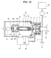
Application to Liquid Chromatography
The ion source according to the present invention is further
applicable as the ion source to be used in a liquid chromatograph mass
spectrometer. A construction of the liquid chromatograph mass
spectrometer is shown in Fig. 16. Namely, an eluate from the liquids
chromatograph 36 is vaporized by an appropriate vaporizer (comprising a
conduit 59 for spraying by heating or by gas). Then, the vapor is
introduced into the ion source of the present invention to ionization, and
the generated ion is detected by the mass spectrometer. Employing the
ion source of the present invention, since the sample can be ionized at
high efficiency, sensitivity in detection can significantly enhanced. In
Fig. 17, heating type vaporizer 37 is employed. Namely, a metal block is
welled to the conduit 59. The metal block 60 can be controlled a
temperature by a thermocouple 62 and a cartridge heater 61. The
eluate from the liquid chromatograph 36 is converted into a fine liquid
droplet in the terminal at the end of the conduit 59.
As set forth above, according to the present invention, since the
direction of flow of the sample relative to the corona discharge region and
the direction to extract the ion by corona discharge are different.
Therefore, a presence period of the intermediate in the corona discharge
region can be shortened. Therefore, the ion of the objective sample can
be efficiently generated. Also, according to the present invention, high
selectivity and high sensitivity measurement of the ion of the sample
becomes possible. In addition, even when deposition is deposited at the
tip end of the needle electrode, discharge can be maintained stably for a
long period, for example 2 months or more.
Although the present invention has been illustrated and
described with respect to exemplary embodiment thereof, it should be
understood by those skilled in the art that the foregoing and various
other changes, omissions and additions may be made therein and
thereto, without departing from the spirit and scope of the present
invention. Therefore, the present invention should not be understood
as limited to the specific embodiment set out above but to include all
possible embodiments which can be embodied within a scope
encompassed and equivalents thereof with respect to the feature set out
in the appended claims.