EP1090716B1 - Gezielte Linsenform Messvorrichtung und Brillenglaslinsen Bearbeitungsvorrichtung mit derselben - Google Patents
Gezielte Linsenform Messvorrichtung und Brillenglaslinsen Bearbeitungsvorrichtung mit derselben Download PDFInfo
- Publication number
- EP1090716B1 EP1090716B1 EP00121963A EP00121963A EP1090716B1 EP 1090716 B1 EP1090716 B1 EP 1090716B1 EP 00121963 A EP00121963 A EP 00121963A EP 00121963 A EP00121963 A EP 00121963A EP 1090716 B1 EP1090716 B1 EP 1090716B1
- Authority
- EP
- European Patent Office
- Prior art keywords
- base
- lens
- movement
- feeler
- calibration
- Prior art date
- Legal status (The legal status is an assumption and is not a legal conclusion. Google has not performed a legal analysis and makes no representation as to the accuracy of the status listed.)
- Expired - Lifetime
Links
Images


Classifications
-
- B—PERFORMING OPERATIONS; TRANSPORTING
- B24—GRINDING; POLISHING
- B24B—MACHINES, DEVICES, OR PROCESSES FOR GRINDING OR POLISHING; DRESSING OR CONDITIONING OF ABRADING SURFACES; FEEDING OF GRINDING, POLISHING, OR LAPPING AGENTS
- B24B9/00—Machines or devices designed for grinding edges or bevels on work or for removing burrs; Accessories therefor
- B24B9/02—Machines or devices designed for grinding edges or bevels on work or for removing burrs; Accessories therefor characterised by a special design with respect to properties of materials specific to articles to be ground
- B24B9/06—Machines or devices designed for grinding edges or bevels on work or for removing burrs; Accessories therefor characterised by a special design with respect to properties of materials specific to articles to be ground of non-metallic inorganic material, e.g. stone, ceramics, porcelain
- B24B9/08—Machines or devices designed for grinding edges or bevels on work or for removing burrs; Accessories therefor characterised by a special design with respect to properties of materials specific to articles to be ground of non-metallic inorganic material, e.g. stone, ceramics, porcelain of glass
- B24B9/14—Machines or devices designed for grinding edges or bevels on work or for removing burrs; Accessories therefor characterised by a special design with respect to properties of materials specific to articles to be ground of non-metallic inorganic material, e.g. stone, ceramics, porcelain of glass of optical work, e.g. lenses, prisms
- B24B9/144—Machines or devices designed for grinding edges or bevels on work or for removing burrs; Accessories therefor characterised by a special design with respect to properties of materials specific to articles to be ground of non-metallic inorganic material, e.g. stone, ceramics, porcelain of glass of optical work, e.g. lenses, prisms the spectacles being used as a template
-
- B—PERFORMING OPERATIONS; TRANSPORTING
- B24—GRINDING; POLISHING
- B24B—MACHINES, DEVICES, OR PROCESSES FOR GRINDING OR POLISHING; DRESSING OR CONDITIONING OF ABRADING SURFACES; FEEDING OF GRINDING, POLISHING, OR LAPPING AGENTS
- B24B17/00—Special adaptations of machines or devices for grinding controlled by patterns, drawings, magnetic tapes or the like; Accessories therefor
- B24B17/10—Special adaptations of machines or devices for grinding controlled by patterns, drawings, magnetic tapes or the like; Accessories therefor involving electrical transmission means only, e.g. controlled by magnetic tape
Definitions
- the present invention relates to a target-lens-shape measuring device for measuring a target lens shape (a traced outline) of a template (a pattern), a dummy lens, a lens frame of an eyeglass frame, or the like, and an eyeglass-lens processing apparatus having the target-lens-shape measuring device.
- the target lens shape (the traced outline) is generally measured by detecting the amount of movement of a frame feeler (a stylus) which is brought into contact with a frame groove of a lens frame of an eyeglass frame, or a template feeler (a tracing pin) which is brought into contact with a side surface of a template or dummy lens (hereafter, each of these feelers will be simply referred to as the feeler).
- a frame feeler a stylus
- a template feeler a tracing pin
- a method for detecting the amount of movement of the feeler is carried out in the following manner: A rack-and-pinion mechanism or a mechanism including a wire (or a belt) and pulleys combined together is used to convert the linear movement of the feeler into rotational motion, and the amount of the rotation motion is detected by a rotation detector such as an encoder, thereby obtaining the amount of movement of the feeler.
- the above-described detection method suffers from a problem in that a deviation may occur between the actual amount of movement of the feeler and the amount of movement of the feeler detected on the basis of an output from the encoder, resulting in an inaccurate result of measurement. Further, the same problem is also applied to the mechanism including the wire (or the belt), and pulleys.
- a target-lens-shape measuring device which makes it possible to conduct highly accurate calibration with respect to the amount of movement of the feeler over a wide-ranging stroke without the use of a special measuring instrument or jig.
- Another object of the invention is to provide an eyeglass-lens processing apparatus having such target-lens-shape measuring device.
- the present invention provides a target lens shape measuring device according to the appended claims.
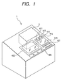
- Fig. 1 is a diagram illustrating the external configuration of an eyeglass-lens processing apparatus (a lens edger, the same is applied hereafter) in accordance with the invention.
- a target-lens-shape measuring device i.e. an eyeglass-frame-shape measuring device (a frame tracer, the same is applied hereafter), 2 is incorporated in an upper right-hand rear portion of a main body 1 of the apparatus.
- the target-lens-shape measuring device 2 is disposed in such a manner as to be inclined toward a front side along the inclination of the upper surface of the casing of the main body 1 so as to facilitate the setting of an eyeglass frame on a frame holding section 200 which will be described later.
- a switch panel section 410 having switches for operating the target-lens-shape measuring device 2 and a display 415 for displaying processing information and the like are disposed in front of the target-lens-shape measuring device 2.
- reference numeral 420 denotes a switch panel section having various switches for inputting processing conditions and the like and for giving instructions for processing
- numeral 402 denotes an openable window for a processing chamber.
- Fig. 2 is a perspective view illustrating the arrangement of a lens processing section 800 disposed in the casing of the main body 1.
- a carriage unit 700 is mounted on a base 10, and a subject lens LE clamped by a pair of lens chuck shafts 702L and 702R of a carriage 701 is ground by a group of abrasive wheels 602 attached to a rotating shaft 601.
- the rotating shaft 601 is rotatably attached to the base 10 by a spindle 603.
- a pulley 604 is attached to an end of the rotating shaft 601, and is linked through a belt 605 to a pulley 607 which is attached to a rotating shaft of an abrasive-wheel rotating motor 606.
- the lens LE is subjected to grinding process by variably controlling an axis-to-axis distance between the lens chuck shafts 702L, 702R and the abrasive wheel rotating shaft 601 with a main control section 160 (see Fig. 17).
- a lens-shape measuring section 500 is provided in the rear of the carriage 701.
- Fig. 3 is a plan view of the frame holding section 200
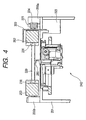
- Fig. 4 is a cross-sectional view taken along line A - A in Fig. 3 and illustrating an essential portion.
- a front slider 202 and a rear slider 203 for holding an eyeglass frame are slidably placed on a pair of guide rails 204 and 205 arranged on the right- and left-hand sides of a holding section base 201.
- Pulleys 207 and 208 are rotatably attached respectively to a front-side block 206a and a rear-side block 206b that support the guide rail 204.
- An endless wire 209 is suspended on the pulleys 207 and 208.
- An upper side of the wire 209 is secured to a pin 210 attached to a right end member 203R extending from the rear slider 203, while a lower side of the wire 209 is secured to a pin 211 attached to a right end member 202R extending from the front slider 202.
- a spring 213 is stretched between the rear-side block 206b and the right end member 202R using a mounting plate 212, so that the front slider 202 is constantly urged in the direction in which the spring 213 contracts.
- the front slider 202 and the rear slider 203 are slid in a symmetrically opposing manner with respect to a reference line L1 at the center therebtween, and are constantly pulled in directions toward that center (reference line L1) by the spring 213.
- the frame is clamped by clamp pins 230 arranged at total four locations, i.e. by clamp pins 230 at right and left two locations of the front slider 202 and clamp pins 230 at right and left locations of the rear slider 203, so as to be held in a reference plane for measurement.
- clamp pins 230 are effected by driving a clamp motor 223 which is fixed on the reverse side of the holding section base 201.
- a worm gear 224 attached to a rotating shaft of the motor 223 is in mesh with a wheel gear 221 of a shaft 220 which is rotatably held between the block 206a and the block 206b, so that the rotation of the motor 223 is transmitted to the shaft 220.
- the shaft 220 is passed through the right end member 202R and the right end member 203R.
- an unillustrated wire for opening and closing the clamp pins 230 is attached to the shaft 220, and as the wire is pulled by the rotation of the shaft 220, the opening and closing operation of the clamp pins 230 are effected simultaneously.
- an unillustrated similar wire is also attached to the shaft 220, and the opening and closing operation of the clamp pins 230 are effected simultaneously by the rotation of the shaft 220.
- brake pads for securing the opening and closing of the front slider 202 and the rear slider 203 due to the rotation of the shaft 220 are respectively provided inside the right end member 202R and the right end member 203R.
- an attaching plate 300 for attaching a template holder 310 (described later), which is used at the time of measuring a template (a pattern, the same is applied hereafter) 350 (or a dummy lens), is fixed at the center on the front side of the holding section base 201 as shown in Fig. 4.
- the attaching plate 300 has an inverse L-shaped cross section, and the template holder 310 is used upon being placed on the upper surface of the attaching plate 300.
- a magnet 301 is provided in the center of the upper surface of the attaching plate 300, and two holes 302 for positioning the template holder 310 are formed in the attaching plate 300 on the left- and right-hand sides of the magnet 301.
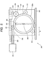
- Fig. 5 is a plan view of the measuring section 240.
- a transversely movable base 241 is supported in such a manner as to be transversely slidable along two rails 242 and 243 which are axially supported by the holding section base 201 and extend in the transverse direction (in the arrow B direction).
- the transverse movement of the transversely movable base 241 is effected by the driving of a pulse motor 244 attached to the holding section base 201.
- a feed screw 245 is connected to a rotating shaft of the motor 244, and as the feed screw 245 meshes with a female threaded member 246 fixed on the lower side of the transversely movable base 241, the transversely movable base 241 is moved in the transverse direction (in the arrow B direction) by the forward and reverse rotation of the motor 244.
- a rotating base 250 is rotatably held on the transversely movable base 241 by rollers 251 provided at three positions.
- a geared portion 250a is formed around a circumference of the rotating base 250, and an angular or tapered guide rail 250b projecting in a radially outward direction is formed below the geared portion 250a.
- This guide rail 250b is brought into contact with a V-shaped groove of each roller 251, and the rotating base 250 rotates while being held by the three rollers 251.
- the geared portion 250a of the rotating base 250 meshes with an idle gear 252, and the idle gear 252 meshes with a gear 253 attached to a rotating shaft of a pulse motor 254 secured to the lower side of the transversely movable base 241.
- a pulse motor 254 secured to the lower side of the transversely movable base 241.
- a feeler unit 255 is attached to the underside of the rotating base 250.
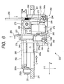
- Fig. 6 is a side elevational view for explaining the feeler unit 255
- Fig. 7 is a view taken in the direction of arrow C in Fig. 6.
- a fixed block 256 is fixed to the underside of the rotating base 250.
- a guide rail receiver 256a is attached to a side surface of the fixed block 256 in such a manner as to extend in the planar direction of the rotating base 250.
- a transversely movable supporting base 260 having a slide rail 261 is attached to the guide rail receiver 256a to be slidable in the lateral direction (in the arrow F direction).
- a DC motor 257 for moving the transversely movable supporting base 260 and an encoder 258 for detecting the amount of its movement are attached to a side of the fixed block 256 which is opposite to its side where the guide rail receiver 256a is attached.
- a gear 258a attached to a rotating shaft of the encoder 258 meshes with a rack 262 fixed to a lower portion of the transversely movable supporting base 260 so that the amount of the movement of the transversely movable supporting base 260 is detected based on the rotation thereof.
- the rotation of a gear 257a attached to the rotating shaft of the motor 257 is transmitted through an idle gear 259 to the gear 258a to move the rack 262, thereby moving the transversely movable supporting base 260 in the lateral direction (in the arrow F direction) in Fig. 6.
- a vertically movable supporting base 265 is supported by the transversely movable supporting base 260 to be movable in the vertical direction (in the arrow G direction).
- a slide rail (not shown) attached to the vertically movable supporting base 265 is slidably held on a guide rail receiver 266 attached to the transversely movable supporting base 260 and extending in the vertical direction.
- a vertically extending rack 268 is secured to the vertically movable supporting base 265, and a gear 272a of an encoder 272 attached to the transversely movable supporting base 260 by means of a fixing metal plate meshes with the rack 268.
- the amount of the movement of the vertically movable supporting base 264 is detected by the encoder 272.
- the rotation of a gear 270a which is attached to a rotating shaft of a DC motor 270, is transmitted through an idle gear 271 to the gear 272a to move the rack 268, thereby moving the vertically movable supporting base 265 in the vertical direction (in the arrow G direction).
- a downward load of the vertically movable supporting base 265 is reduced by a power spring 275 attached to the transversely movable supporting base 260, thereby rendering the vertical movement of the vertically movable supporting base 265 smooth.
- a shaft 276 is rotatably held on the vertically movable supporting base 265, an L-shaped attaching member 277 is provided at its upper end, and a feeler (a stylus, the same is applied hereafter), i.e. a frame feeler, 280 is fixed to an upper portion of the attaching member 277.
- the tip of the feeler 280 is aligned with a rotational axis of the shaft 276, and the tip of the feeler 280 is to be brought into contact with a frame groove of the frame.
- a limiting member 281 is attached to a lower end of the shaft 276.
- This limiting member 281 has a substantially hollow cylindrical shape, and a protrusion 281a is formed on its side surface along the vertical direction (the arrow G direction), while another protrusion 281a is formed on the opposite side opposite with respect to the paper surface of Fig. 6.
- these two protrusions 281a respectively abut against notched surfaces 265a (the illustrated notched surface 265a, and a similar notched surface 265a that is provided on the opposite side with respect to the paper surface of Fig. 6) formed in the vertically movable supporting base 265, the rotation of the shaft 276 (i.e., the rotation of the feeler 280) is limited to a certain range.
- An obliquely cut slanting surface is formed on a lower portion of the limiting member 281.
- this slanting surface abuts against a slanting surface of a block 263 secured to the transversely movable supporting base 260.
- the rotation of the limiting member 281 is guided to the state shown in Fig. 6, thereby correcting the orientation of the tip of the feeler 280.
- a measuring shaft (a tracing pin, the same is applied hereafter), i.e. a template feeler, 290 for template measurement is held on a right-hand side portion of the transversely movable supporting base 260 to be slidable in the vertical direction (in the arrow G direction).
- a pin 291 extending toward the paper surface as viewed in Fig. 6 is attached to a lower end of the measuring shaft 290, and a spring 292 is stretched between this pin 291 and an upper portion of the transversely movable supporting base 260, thereby constantly urging the measuring shaft 290 in the upward direction.
- the pin 291 is provided with a lock mechanism 293.
- the lock mechanism 293 has a fixing plate 295 which rotates about a shaft 294 as well as a coil spring 296 which urges the fixing plate 295 in the rightward direction in Fig. 6. If the measuring shaft 290 is pushed into the interior of the movable supporting base 260 against the urging force of the spring 292, the pin 291 rotates the fixing plate 295 in the leftward direction in Fig. 6 while abutting against the fixing plate 295. Further, if the measuring shaft 290 is pushed in, the pin 291 is located below the fixing plate 295, and the fixing plate 295 is returned to the right side by the urging force of the coil spring 296.
- the pin 291 enters below a notched portion of the fixing plate 295, and the measuring shaft 290 is locked in a state of being accommodated inside the transversely movable supporting base 260.
- the pushing in of the top portion of the measuring shaft 290 causes the pin 291 to be disengaged from the notched portion while being guided by a guide plate 295a formed on the fixing plate 295, and the measuring shaft 290 is raised to an upper predetermined position by the urging force of the spring 292.
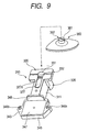
- Fig. 8 is a perspective view of the template holder 310 in a state in which a template holding portion 320 for mounting a template 350 thereon is oriented upward.
- Fig. 9 is a perspective view of the template holder 310 in a state in which a cup holding portion 330 for mounting a dummy lens thereon is oriented upward.
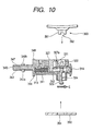
- Fig. 10 is a longitudinal cross-sectional view of the template holder 310.
- the template holding portion 320 and the cup holding portion 330 are provided integrally on opposite surfaces, respectively, of a main body block 311 of the template holder 310 so that the template holding portion 320 and the cup holding portion 330 can be selectively used by inverting the template holder 310.
- Pins 321a and 321b are implanted on the template holding portion 320, an opening 322 is provided in the center, and a movable pin 323 projects from the opening 322.
- the movable pin 323 is fixed to a movable shaft 312 inserted in the main body block 311, and the movable shaft 312 is constantly urged in the direction of arrow E in Fig. 10 by a spring 313.
- a button 314 for performing a pushing operating is attached to a distal end of the movable shaft 312 projecting from the main body block 311. Further, a recessed portion 324 is formed on the front side (right-hand side in Fig. 10) of the movable pin 323.
- a hole 331 for inserting a basal part 361 of a cup 360 with a dummy lens fixed thereon is formed in the cup holding portion 330, and a projection 332 for fitting to a key groove 362 formed in the basal part 361 is formed inside the hole 331.
- a sliding member 327 is fixed to the movable shaft 312 inserted in the main body block 311, and its front-side end face 327a is circular-arc shaped (a circular arc of the same diameter as that of the hole 331).
- the template 350 is positioned such that a central hole 351 formed in the template 350 is fitted over the movable pin 323 while two small holes 352 provided on both sides of the central hole 351 are engaged with the pins 321a and 321b. Subsequently, if the button 314 pushed in toward the main body block 311 side is released, the movable pin 323 is returned in the direction of arrow E by the urging force of the spring 313, and its recessed portion 324 abuts against the wall of the central hole 351 in the template 350, thereby fixing the template 350.
- the button 314 is manually pushed in to open the sliding member 327
- the key groove 362 of the basal part 361 is fitted to the projection 332.
- the sliding member 327 together with the movable shaft 312 is returned toward the hole 331 by the urging force of the spring 313.
- the basal part 361 of the cup 360 inserted in the hole 331 is pressed by the circular-arc shaped end face 327a, the cup 360 is fixed in the cup holding portion 330.
- a fitting portion 340 for fitting the template holder 310 to the attaching plate 300 of the holding section base 201 is provided on the rear side of the main body block 311, and its obverse side (the template holding portion 320 side is assumed to be the obverse side) has the same configuration as the reverse side.
- Pins 342a, 342b and 346a, 346b for insertion into the two holes 302 formed in the upper surface of the attaching plate 300 are respectively implanted on the obverse surface 341 and the reverse surface 345 of the fitting portion 340.
- iron plates 343 and 347 are respectively embedded in the obverse surface 341 and the reverse surface 345.
- Flanges 344 and 348 are respectively formed on the obverse surface 341 and the reverse surface 345 of the fitting portion 340.
- the template holding portion 320 side is oriented downward, and the pins 342a and 342b on the fitting portion 340 are engaged in the holes 302 in the attaching plate 300.
- the iron plate 343 is attracted by the magnet 301 provided on the upper surface of the attaching plate 300, the template holder 310 can be easily fixed immovaly to the upper surface of the attaching plate 300.
- the flange 344 of the template holder 310 abuts against a recessed surface 202a formed in the center of the front slider 202 to maintain the open state of the front slider 202 and the rear slider 203.
- the frame is placed between the clamp pins 230. Since centripetal forces for moving toward the reference line L1 are constantly acting in the front slider 202 and the rear slider 203 owing to the spring 213, the distance between the two sliders 202 and 203 is thereby narrowed, and the frame is held with the reference line L1 as the center.
- a both-eye tracing switch 412 of the switch panel section 410 is pressed. Then, a control unit 150 on the target-lens-shape measuring device 2 drives the motor 223, and as the shaft 220 is rotated, the clamp pins at four locations are closed to clamp and fix the frame. Subsequently, the measuring section 240 is operated to measure the target lens shape.
- the control unit 150 moves the transversely movable base 241 in advance by driving the motor 244 so that the feeler 280 is located at a predetermined position on the right lens frame portion of the frame. Subsequently, the vertically movable supporting base 265 is raised by driving the motor 270 to allow the feeler 280 to be located at the height of the measurement reference plane. The amount of movement at the time the feeler 280 is raised from a lowest-point position can be obtained from the detection by the encoder 272, and the control unit 150 causes the feeler 280 to be located at the height of the measurement reference plane on the basis of the detection information of the encoder 272.
- the control unit 150 drives the motor 257 to move the transversely movable supporting base 260, and thereby allows the tip of the feeler 280 to be inserted in the frame groove of the lens frame.
- the driving current (driving torque) to the motor 257 can be controlled to provide a predetermined driving force. Therefore, it is possible to impart a weak pressing force of such a degree that the frame is not deformed and that the feeler 280 is not dislocated.
- the motor 254 is rotated in accordance with each predetermined unit number of rotational pulses to rotate the feeler unit 255 together with the rotating base 250.
- the transversely movable supporting base 260 together with the feeler 280 is moved transversely (in the direction of arrow F) in accordance with the radius vector of the frame groove, and the amount of its movement is detected by the encoder 258. That is, the amount of movement of the feeler 280 in the direction of the radius vector with respect to the target lens shape is detected by the encoder 258.
- the vertically supporting base 265 together with the feeler 280 is moved vertically (in the direction of arrow G) along the warp (curve) of the frame groove, and its amount of movement is detected by the encoder 272.
- the control unit 150 drives the motor 244 to move the transversely movable base 241 so that the feeler 280 is located at a predetermined position on the left lens frame portion of the frame, and the target lens shape of the left lens frame portion is measured in a similar manner.
- the target lens shape data measured as described above is transferred to a data memory 161 on the processing apparatus side, and is used as processing information.
- the measuring shaft 290 instead of the feeler 280 is used to trace the periphery of the template or the dummy lens, so that the amount of movement of the measuring shaft 290 in the direction of the radius vector is detected by the encoder 258 in the same way as the above-described frame measurement, and the target lens shape of the template is measured on the basis of the amount of movement thus detected and the rotation angle ⁇ of the motor 254.
- the template or the dummy lens is mounted to the template holding portion 320 or the cup holding portion 330 of the template holder 310 in the above-described procedure.
- the front slider 202 is pulled toward the front side, and the template holder 310 is fixed onto the upper surface of the attaching plate 300. Since the flange 344 (348) of the template holder 310 is engaged in the recessed surface 202a of the front slider 202, the open state of the front slider 202 and the rear slider 203 is fixed.
- the open state of the front slider 202 is detected by a sensor plate and a sensor 235 so that the template measurement mode is detected.
- a right trace switch 413 on the switch panel section 410 is pressed, whereas in a case where it is for the left use, a left trace switch 411 is pressed.
- the apex portion of the measuring shaft 290 is pressed to raise the measuring shaft 290.
- the control unit 150 drives the motor 244 to position the transversely movable base 241 at the measuring position in the center. Subsequently, the motor 257 is driven to move the transversely movable supporting base 260 such that the measuring shaft 290 is oriented toward the central side. In a state in which the measuring shaft 290 abuts against the end face of the template (or the dummy lens), the motor 254 is rotated in accordance with each predetermined unit number of rotational pulses to rotate the feeler unit 255. The measuring shaft 290 is moved in accordance with the radius vector of the template, and the amount of its movement is detected by the encoder 258.
- the amount of movement of the feeler (the feeler 280 or the measuring shaft 290) in the radius vector direction is obtained on the basis of the output signal (number of pulses) from the encoder 258.
- the accuracy of the obtained amount largely depends on the processing accuracy (structural precision) of the gear 258a attached to the rotating shaft of the encoder 258 as well as the rack 262.
- the axis of the gear 258a is eccentric to the rotating shaft of the encoder 258, a periodically changing error is contained in the detected amount of movement of the transversely movable supporting base 260. This hinders measurement of the target lens shape with high accuracy.
- the moving mechanism using the feed screw is generally capable of realizing high-accuracy movement at remarkably lower cost as compared with the moving mechanism using the rack and the gear (pinion). Accordingly, in the present device, the linearity calibration with respect to the amount of movement of the transversely movable supporting base 260 (the feeler 280 and the measuring shaft 290) is conducted using the movement of the transversely movable base 241 by the feed screw 245.
- this calibration will be given of this calibration with reference to Figs. 11 to 16.
- Fig. 11 is a diagram explaining the flow of the linearity calibration.
- Fig. 12 is a diagram explaining the operation of the linearity calibration.
- reference numeral 901 denotes a limiting plate for limiting the movement of the feeler 280 in the leftward direction (in the B1 direction) of Fig. 12.
- the limiting plate 901 has a shape modeled like an eyeglass frame in order to enable the calibration with respect to the entire target lens shape.
- a measurement groove 901a is provided to the reverse side of the limiting plate 901 in a central portion thereof to provide to a step portion. The calibration is conducted with the feeler 280 kept in abutment against the measurement groove 901a.
- the limiting plate 901 is clamped and fixed by the clamp pins 230 in the similar manner to the case where the frame is fixed.
- a program for calibration preliminarily stored in the control unit 150 is executed.
- the control unit 150 drives the motor 257 to move the transversely movable supporting base 260 to a movement limit position in the rightward direction (in the B2 direction) in Fig. 12A (this movement limit position corresponds to a movement home position shown in Fig. 6). Further, a count value of the encoder 258 by this movement is cleared to be the original point.
- the rotating base 250 is rotated by the motor 254 so that the direction in which the transversely movable supporting base 260 is moved (F direction) and the direction in which the transversely movable base 241 is moved (B direction) are set to be identical to each other.
- the transversely movable supporting base 260 is moved in the leftward direction (in the B1 direction) by the motor 257 until the feeler 280 abuts against the measurement groove 901a, and a value (number of pulses) outputted from the encoder 258 at this time is obtained.
- the transversely movable base 241 is moved in the leftward direction (in the B1 direction) by driving the motor 244 until the value of the encoder 258 obtained is returned to the original point. This causes the transversely movable supporting base 260 to be set at the movement home position (at the position shown in Fig. 12A).
- the transversely movable base 241 is moved until the value of the encoder 258 is returned to the value of the original point + a (the value before the original value by a predetermined number of pulses), that is, until the transversely movable supporting base 260 is set to be a position slightly before the movement home position.
- the linearity measurement is conducted as described below. While a predetermined driving torque is generated under control of the driving current to the motor 257 to hold the feeler 280 in abutment against the limiting plate 901, the transversely movable base 241 is moved rightward (in the B2 direction) by driving the motor 244. During this movement, the number of pulses of the motor 244 for moving the transversely movable base 241 is consecutively stored every time the value (number of pulses) outputted from the encoder 258 changes. Based on this procedure, a calibration table for the amount of movement of the transversely movable supporting base 260 with respect to the value of the encoder 258 is prepared.
- the completion of measurement is determined as follows.
- the transversely movable supporting base 260 having the feeler 280 is moved leftward relative to the fixed block 256.
- the transversely movable supporting base 260 reaches the movement limit position (the position shown in Fig. 12B) in the leftward direction (in the B1 direction), and further the transversely movable base 241 is moved in the rightward direction (in the B2 direction)
- the feeler 280 is released from the limiting plate 901, so that the value of the encoder 258 ceases to change.
- control unit 150 detects that measurement data over the entire stroke by which the transversely movable supporting base 260 is moved (the number of pulses of the motor 244 with respect to the value of the encoder 258) has been obtained, thereby finishing the linearity measurement.
- the amount of movement of the transversely movable base 241 with respect to the number of pulses of the motor 244 is a known value obtainable from a design specification, namely from the pitch of the feed screw 245 and the amount of rotation of the feed screw corresponding to the number of pulses of the motor 244. Accordingly, if the number of pulses of the motor 244 is obtained, the amount of the movement of the transversely movable base 241, that is, the amount of movement of the transversely movable supporting base 260 with respect to the value of the encoder 258, is obtained. To prepare the calibration table, the control unit 150 converts the number of pulses of the motor 244 into an actual distance of movement, and stores the distance in a memory 151.
- the calibration table for the amount of movement of the transversely movable supporting base 260 with respect to the value of the encoder 258 is prepared as described above, the calibration table is referred to during the actual measurement of the target lens shape. Accordingly, the target lens shape can be measured with high accuracy even though the measuring mechanism uses the rack and the pinion.
- the calibration table stored in the memory (RAM) 151 may be stored in a nonvolatile memory 152 as it is, and may be used by being transferred to the memory 151 side during the starting of the device. To save the capacity of the memory, however, the following procedure may be taken, for example.
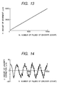
- a relationship as shown in Fig. 13 stands between the number (N) of pulses of the encoder 258 and the amount (Y) of movement of the transversely movable supporting base 260 obtained from the motor 244 in the calibration table thus prepared.
- N the number of pulses of the encoder 258
- Y the amount of movement of the transversely movable supporting base 260 obtained from the motor 244 in the calibration table thus prepared.
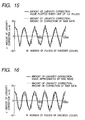
- a new table is prepared, indicating the amount of linearity correction, y, in relation to number of pulses, N.
- This table is shown in Fig. 14.
- the table of the amount of correction as shown in Fig. 13 is prepared again through calculation from the above formula for determining Y' and the table of the amount of linearity correction as shown in Fig. 14, and the thus prepared table is stored in the memory 151 for use in measurement.
- the amount of linearity correction y may be approximated such that values in the amount of linearity correction y are intermittently stored at fixed intervals, i.e. every unit number of pulses (for example, every 100 pulses), and the rest of values between the adjacent stored values are linearly interpolated as shown by the solid line in Fig. 15. Furthermore, as shown in Fig. 16, if the amount of linearity correction y with respect to the number of pulses N is stored in the form of an arithmetic expression in which it is approximated by a sine wave, the memory capacity of the nonvolatile memory 152 can be saved even further. The way of obtaining and storing data is appropriately selected, taking into account the required level of accuracy.
- the target lens shape can be measured with high accuracy.
Landscapes
- Engineering & Computer Science (AREA)
- Mechanical Engineering (AREA)
- Chemical & Material Sciences (AREA)
- Ceramic Engineering (AREA)
- Inorganic Chemistry (AREA)
- Eyeglasses (AREA)
- A Measuring Device Byusing Mechanical Method (AREA)
- Grinding And Polishing Of Tertiary Curved Surfaces And Surfaces With Complex Shapes (AREA)
Claims (17)
- Ziellinsenform-Messvorrichtung (2) zum Messen einer Ziellinsenform, die zum Bearbeiten einer Brillenlinse verwendet wird, wobei die Vorrichtung umfasst:wobei die zweite Erfassungseinrichtung eine höhere Erfassungsgenauigkeit aufweist als die erste Erfassungseinrichtung;eine Halteeinrichtung (200, 310) zum Halten eines Linsenrahmens eines Brillenrahmens, einer Schablone oder einer Dummy-Linse in einem vorbestimmten Zustand;eine Haltebasis (241, 250, 260, 265) zum Halten eines Fühlers (280, 290), damit dieser in einer Radiusvektorrichtung der Ziellinsenform beweglich ist;eine erste Erfassungseinrichtung (258, 258a, 262) zum Erfassen der Bewegung des Fühlers in der Radiusvektorrichtung;eine Recheneinrichtung (150), die ausgelegt ist, um Radiusvektordaten der Ziellinsenform auf der Grundlage des Erfassungsergebnisses von der ersten Erfassungseinrichtung zu erhalten;eine Bewegungseinrichtung (244, 245, 246) zum relativen Bewegen der Haltebasis in der Radiusvektorrichtung der Ziellinsenform in Bezug auf die Halteeinrichtung;eine zweite Erfassungseinrichtung (244) zum Erfassen der Bewegung der Haltebasis durch die Bewegungseinrichtung,
eine Kalibrierungseinrichtung (150), dadurch gekennzeichnet, dass die Kalibrierungseinrichtung ausgelegt ist, um Kalibrierungsdaten auf der Grundlage des Erfassungsergebnisses von der zweiten Erfassungseinrichtung während der Bewegung der Haltebasis durch die Bewegungseinrichtung zu erhalten und zu speichern, und ausgelegt ist, um das Erfassungsergebnis von der ersten Erfassungseinrichtung oder ein Rechenergebnis von der Recheneinrichtung auf der Grundlage der gespeicherten Kalibrierungsdaten zu kalibrieren. - Vorrichtung nach Anspruch 1, wobei die erste Erfassungseinrichtung eine Zahnstange und ein Ritzel zum gemeinsamen Umwandeln der linearen Bewegung des Fühlers in der Radiusvektorrichtung in eine drehende Bewegung und einen Codeumsetzer zum Erfassen eines Ausmaßes der Drehung des Ritzels umfasst.
- Vorrichtung nach Anspruch 1, wobei die Bewegungseinrichtung einen Motor und einen Gewindemechanismus zum Umwandeln der Drehbewegung durch den Motor in eine lineare Bewegung der Haltebasis in der Radiusvektorrichtung umfasst.
- Vorrichtung nach Anspruch 3, wobei die zweite Erfassungseinrichtung ein Ausmaß der Bewegung der Haltebasis auf der Grundlage der Drehinformation des Motors erfasst.
- Vorrichtung nach Anspruch 1, wobei die Bewegungseinrichtung üblicherweise als eine Einrichtung zum Bewegen des Fühlers von einem Messzentrum des Linsenrahmens zu einem Messzentrum eines anderen Linsenrahmens des Brillenrahmens benutzt wird, um diese Linsenrahmen nacheinander zu messen.
- Vorrichtung nach Anspruch 1, ferner umfassend:wobei der Fühler mit dem Anschlagelement in Anschlag gebracht wird, wenn die Kalibrierungsdaten erhalten werden, und die Bewegungseinrichtung bewegt die Haltebasis in einer Richtung entgegengesetzt zu einer Richtung, in welcher der Fühler mit dem Anschlagelement in Anschlag gebracht wird.ein Anschlagelement;
- Vorrichtung nach Anspruch 1, wobei die Kalibrierungseinrichtung das Erfassungsergebnis von der zweiten Erfassungseinrichtung während der Bewegung der Haltebasis durch die Bewegungseinrichtung als die Kalibrierungsdaten zum Kalibrieren des Erfassungsergebnisses von der ersten Erfassungseinrichtung oder als Rechenergebnis von der Recheneinrichtung speichert.
- Vorrichtung nach Anspruch 7, wobei die Kalibrierungseinrichtung die Kalibrierungsdaten in der Form einer Tabelle speichert.
- Vorrichtung nach Anspruch 7, wobei die Kalibrierungseinrichtung das Erfassungsergebnis von der zweiten Erfassungseinrichtung während der Bewegung der Haltebasis in einer vorbestimmten Entfernung durch die Bewegungseinrichtung und eine Rechenformel zur Interpolation des Erfassungsergebnisses als die Kalibrierungsdaten speichert.
- Vorrichtung nach Anspruch 1, wobei die Kalibrierungseinrichtung Korrekturdaten auf der Grundlage der Erfassungsergebnisse von der ersten und der zweiten Erfassungseinrichtung während der Bewegung der Haltebasis durch die Bewegungseinrichtung erhält und die Korrekturdaten als die Kalibrierungsdaten zum Kalibrieren des Erfassungsergebnisses von der ersten Erfassungseinrichtung oder des Rechenergebnisses von der Recheneinrichtung speichert.
- Vorrichtung nach Anspruch 10, wobei die Kalibrierungseinrichtung die Korrekturdaten in der Form einer Tabelle speichert.
- Vorrichtung nach Anspruch 10, wobei die Kalibrierungseinrichtung die Korrekturdaten auf der Grundlage der Erfassungsergebnisse von der ersten und der zweiten Erfassungseinrichtung während der Bewegung der Haltebasis in einer vorbestimmten Entfernung durch die Bewegungseinrichtung und eine Rechenformel zur Interpolation der Korrekturdaten als die Kalibrierungsdaten speichert.
- Vorrichtung nach Anspruch 1, wobei die Haltebasis umfasst:eine quer bewegliche Stützbasis, welche den Fühler hält;eine drehende Basis, welche die quer bewegliche Stützbasis hält, damit diese in der Radiusvektorrichtung beweglich ist; undeine quer bewegliche Basis, welche die drehende Basis hält, damit diese drehbar ist.
- Vorrichtung nach Anspruch 13, wobei
die erste Erfassungseinrichtung eine Bewegung der quer beweglichen Stützbasis als die Bewegung des Fühlers in der Radiusvektorrichtung erfasst; und
die zweite Erfassungseinrichtung eine Bewegung der quer beweglichen Basis als die Bewegung der Haltebasis in der Radiusvektorrichtung erfasst. - Vorrichtung nach Anspruch 1, wobei die Haltebasis den Fühler hält, damit dieser in der Radiusvektorrichtung und in einer Richtung senkrecht zur Radiusvektorrichtung beweglich ist.
- Vorrichtung nach Anspruch 15, wobei die Haltebasis umfasst:eine vertikal bewegliche Stützbasis, welche den Fühler hält;eine quer bewegliche Stützbasis, welche die vertikal bewegliche Stützbasis hält, damit diese vertikal beweglich ist;eine drehende Basis, welche die quer bewegliche Stützbasis hält, damit diese in der Radiusvektorrichtung beweglich ist; undeine quer bewegliche Basis, welche die drehende Basis hält, damit diese drehbar ist.
- Brillenlinsen-Bearbeitungsvorrichtung, ausgestattet mit der Ziellinsenform-Messvorrichtung des Anspruchs 1, zum Bearbeiten der Brillenlinse auf der Grundlage der erhaltenen Ziellinsenform, wobei die Vorrichtung umfasst:eine Linsenbearbeitungseinrichtung mit einer drehbaren Schleifscheibe und einer Linsendrehwelle, welche die Linse hält und dreht; undeine Steuereinrichtung zum Steuern der Linsenbearbeitungseinrichtung auf der Grundlage der erhaltenen Ziellinsenform.
Applications Claiming Priority (2)
| Application Number | Priority Date | Filing Date | Title |
|---|---|---|---|
| JP28686599A JP4194192B2 (ja) | 1999-10-07 | 1999-10-07 | 玉型形状測定装置 |
| JP28686599 | 1999-10-07 |
Publications (3)
| Publication Number | Publication Date |
|---|---|
| EP1090716A2 EP1090716A2 (de) | 2001-04-11 |
| EP1090716A3 EP1090716A3 (de) | 2003-10-22 |
| EP1090716B1 true EP1090716B1 (de) | 2005-05-04 |
Family
ID=17710024
Family Applications (1)
| Application Number | Title | Priority Date | Filing Date |
|---|---|---|---|
| EP00121963A Expired - Lifetime EP1090716B1 (de) | 1999-10-07 | 2000-10-09 | Gezielte Linsenform Messvorrichtung und Brillenglaslinsen Bearbeitungsvorrichtung mit derselben |
Country Status (5)
| Country | Link |
|---|---|
| US (1) | US6427350B1 (de) |
| EP (1) | EP1090716B1 (de) |
| JP (1) | JP4194192B2 (de) |
| DE (1) | DE60019865T2 (de) |
| ES (1) | ES2241535T3 (de) |
Families Citing this family (18)
| Publication number | Priority date | Publication date | Assignee | Title |
|---|---|---|---|---|
| JP2002168614A (ja) * | 2000-09-14 | 2002-06-14 | Topcon Corp | 型板保持具 |
| US7090559B2 (en) * | 2003-11-19 | 2006-08-15 | Ait Industries Co. | Ophthalmic lens manufacturing system |
| JP4708035B2 (ja) * | 2005-01-06 | 2011-06-22 | 株式会社ニデック | 眼鏡レンズ加工装置 |
| JP4614279B2 (ja) * | 2005-08-31 | 2011-01-19 | Hoya株式会社 | 眼鏡枠形状測定装置の校正治具 |
| FR2898527B1 (fr) * | 2006-03-15 | 2009-01-16 | Essilor Int | Procede de percage d'une lentille ophtalmique adapte a obtenir la forme et la dimension souhaitees d'un trou a percer dans ladite lentille |
| FR2909578B1 (fr) * | 2006-12-08 | 2009-07-24 | Briot Internat Sa | Procede d'etalonnage d'un ensemble mecanique. |
| FR2910136B1 (fr) * | 2006-12-18 | 2009-02-27 | Essilor Int | Procede de correction de la geometrie d'une couche palpee approchant un brin longitudinal d'un drageoir de monture de lunettes et procede d'acquisition de la geometrie d'un contour d'un tel drageoir |
| WO2008093332A2 (en) * | 2007-01-30 | 2008-08-07 | Zvi Feldman | Systems and methods for producing clip-ons for a primary eyewear |
| JP4974251B2 (ja) * | 2007-02-28 | 2012-07-11 | Hoya株式会社 | 眼鏡枠形状測定装置の校正方法、校正データ作成装置、眼鏡枠形状測定装置、及び、眼鏡枠形状測定校正システム |
| JP5143541B2 (ja) * | 2007-12-19 | 2013-02-13 | 株式会社トプコン | 玉型形状測定装置 |
| JP5139792B2 (ja) * | 2007-12-19 | 2013-02-06 | 株式会社トプコン | 玉型形状測定装置 |
| JP5204527B2 (ja) * | 2008-03-28 | 2013-06-05 | 株式会社トプコン | 玉型形状測定装置 |
| FR2934060B1 (fr) * | 2008-07-18 | 2010-09-24 | Briot Int | Appareil de palpage d'une monture de verres optiques et procede de palpage associe |
| JP5435918B2 (ja) * | 2008-09-30 | 2014-03-05 | 株式会社トプコン | 玉型形状測定方法及びその装置 |
| JP5500579B2 (ja) * | 2009-09-30 | 2014-05-21 | 株式会社ニデック | 眼鏡レンズ加工装置の較正用センサユニット |
| JP5500583B2 (ja) * | 2009-09-30 | 2014-05-21 | 株式会社ニデック | 眼鏡レンズ加工装置 |
| JP5500584B2 (ja) * | 2010-03-02 | 2014-05-21 | 株式会社ニデック | 眼鏡レンズ加工装置 |
| US9535269B2 (en) * | 2013-06-24 | 2017-01-03 | Nidek Co., Ltd. | Eyeglass frame shape measuring apparatus |
Family Cites Families (13)
| Publication number | Priority date | Publication date | Assignee | Title |
|---|---|---|---|---|
| JPH01217086A (ja) | 1988-02-25 | 1989-08-30 | Mitsui Mining & Smelting Co Ltd | 塗料組成物 |
| JP2761590B2 (ja) | 1989-02-07 | 1998-06-04 | 株式会社ニデック | 眼鏡レンズ研削加工機 |
| JP2845945B2 (ja) | 1989-06-07 | 1999-01-13 | 株式会社日立製作所 | マグネトロン |
| JP2925685B2 (ja) | 1990-08-02 | 1999-07-28 | 株式会社ニデック | フレーム形状測定装置 |
| JP2918657B2 (ja) | 1990-08-09 | 1999-07-12 | 株式会社ニデック | 眼鏡レンズ研削加工機 |
| US5333412A (en) * | 1990-08-09 | 1994-08-02 | Nidek Co., Ltd. | Apparatus for and method of obtaining processing information for fitting lenses in eyeglasses frame and eyeglasses grinding machine |
| JP2907974B2 (ja) | 1990-08-28 | 1999-06-21 | 株式会社ニデック | 眼鏡フレームトレース装置 |
| JP3011526B2 (ja) | 1992-02-04 | 2000-02-21 | 株式会社ニデック | レンズ周縁加工機及びレンズ周縁加工方法 |
| JPH07223153A (ja) * | 1994-02-07 | 1995-08-22 | Topcon Corp | フレーム形状測定装置 |
| US6006592A (en) | 1996-11-22 | 1999-12-28 | Kabushiki Kaisha Topcon | Apparatus for measuring the contour of a lens-shaped template formed to be fit in a lens frame of an eyeglass frame |
| EP0844047B1 (de) | 1996-11-22 | 2002-07-17 | Kabushiki Kaisha Topcon | Vorrichtung zum Messen des Umfangs einer linsenförmigen Schablone gefertigt zur Montage in den Rahmen eines Brillengestells |
| JPH1148114A (ja) * | 1997-07-31 | 1999-02-23 | Nidek Co Ltd | 眼鏡枠測定方法及びその装置並びにそれらを備える眼鏡レンズ研削加工装置 |
| US6249991B1 (en) * | 1999-03-17 | 2001-06-26 | National Optronics, Incorporated | Control system for eyeglass tracer |
-
1999
- 1999-10-07 JP JP28686599A patent/JP4194192B2/ja not_active Expired - Fee Related
-
2000
- 2000-10-09 EP EP00121963A patent/EP1090716B1/de not_active Expired - Lifetime
- 2000-10-09 DE DE60019865T patent/DE60019865T2/de not_active Expired - Lifetime
- 2000-10-09 ES ES00121963T patent/ES2241535T3/es not_active Expired - Lifetime
- 2000-10-10 US US09/684,833 patent/US6427350B1/en not_active Expired - Lifetime
Also Published As
| Publication number | Publication date |
|---|---|
| EP1090716A3 (de) | 2003-10-22 |
| US6427350B1 (en) | 2002-08-06 |
| DE60019865T2 (de) | 2006-02-16 |
| ES2241535T3 (es) | 2005-11-01 |
| JP4194192B2 (ja) | 2008-12-10 |
| DE60019865D1 (de) | 2005-06-09 |
| EP1090716A2 (de) | 2001-04-11 |
| JP2001105293A (ja) | 2001-04-17 |
Similar Documents
| Publication | Publication Date | Title |
|---|---|---|
| EP1090716B1 (de) | Gezielte Linsenform Messvorrichtung und Brillenglaslinsen Bearbeitungsvorrichtung mit derselben | |
| US6325700B1 (en) | Eyeglass-frame-shape measuring device and eyeglass-lens processing apparatus having the same | |
| US7681321B2 (en) | Eyeglass frame shape measuring apparatus | |
| US6478657B1 (en) | Eyeglass lens processing apparatus | |
| US6409574B1 (en) | Eyeglass-lens processing apparatus | |
| JP4772342B2 (ja) | 眼鏡レンズ加工装置 | |
| US6702653B2 (en) | Eyeglass lens processing apparatus | |
| US5959199A (en) | Apparatus for measuring the contour of a lens-shaped template formed to be fit in a lens frame of an eyeglass frame | |
| KR101917394B1 (ko) | 안경 프레임 형상 측정 장치 | |
| US6350190B1 (en) | Template holder, target lens shape measuring device having the holder, and eyeglass lens processing apparatus having the device | |
| US6719609B2 (en) | Eyeglass lens processing apparatus | |
| US6006592A (en) | Apparatus for measuring the contour of a lens-shaped template formed to be fit in a lens frame of an eyeglass frame | |
| EP1074340B1 (de) | Gerät zum Messen der Sollform einer Linze und Brillenlinze Bearbeitungsvorrichtung mit demselben | |
| US6497482B1 (en) | Target lens shape measuring device and eyeglass-lens processing apparatus having the same | |
| JP2000317795A (ja) | 型板ホルダー及び玉型形状測定装置 | |
| JPH09117849A (ja) | 被加工レンズコバ厚測定装置 | |
| EP1366857B1 (de) | Vorrichtung zum Bearbeiten von Brillengläsern | |
| JP2514999Y2 (ja) | フレーム形状測定装置 | |
| JP2989208B2 (ja) | メガネの幾何学中心測定器 | |
| JP2512940Y2 (ja) | フレ―ム形状測定装置 |
Legal Events
| Date | Code | Title | Description |
|---|---|---|---|
| PUAI | Public reference made under article 153(3) epc to a published international application that has entered the european phase |
Free format text: ORIGINAL CODE: 0009012 |
|
| AK | Designated contracting states |
Kind code of ref document: A2 Designated state(s): AT BE CH CY DE DK ES FI FR GB GR IE IT LI LU MC NL PT SE |
|
| AX | Request for extension of the european patent |
Free format text: AL;LT;LV;MK;RO;SI |
|
| PUAL | Search report despatched |
Free format text: ORIGINAL CODE: 0009013 |
|
| RIC1 | Information provided on ipc code assigned before grant |
Ipc: 7B 24B 9/14 A Ipc: 7G 02C 13/00 B Ipc: 7B 24B 51/00 B Ipc: 7B 24B 47/22 B |
|
| AK | Designated contracting states |
Kind code of ref document: A3 Designated state(s): AT BE CH CY DE DK ES FI FR GB GR IE IT LI LU MC NL PT SE |
|
| AX | Request for extension of the european patent |
Extension state: AL LT LV MK RO SI |
|
| 17P | Request for examination filed |
Effective date: 20040108 |
|
| AKX | Designation fees paid |
Designated state(s): DE ES FR GB |
|
| GRAP | Despatch of communication of intention to grant a patent |
Free format text: ORIGINAL CODE: EPIDOSNIGR1 |
|
| GRAS | Grant fee paid |
Free format text: ORIGINAL CODE: EPIDOSNIGR3 |
|
| GRAA | (expected) grant |
Free format text: ORIGINAL CODE: 0009210 |
|
| AK | Designated contracting states |
Kind code of ref document: B1 Designated state(s): DE ES FR GB |
|
| REG | Reference to a national code |
Ref country code: GB Ref legal event code: FG4D |
|
| REG | Reference to a national code |
Ref country code: IE Ref legal event code: FG4D |
|
| REF | Corresponds to: |
Ref document number: 60019865 Country of ref document: DE Date of ref document: 20050609 Kind code of ref document: P |
|
| REG | Reference to a national code |
Ref country code: ES Ref legal event code: FG2A Ref document number: 2241535 Country of ref document: ES Kind code of ref document: T3 |
|
| ET | Fr: translation filed | ||
| PLBE | No opposition filed within time limit |
Free format text: ORIGINAL CODE: 0009261 |
|
| STAA | Information on the status of an ep patent application or granted ep patent |
Free format text: STATUS: NO OPPOSITION FILED WITHIN TIME LIMIT |
|
| 26N | No opposition filed |
Effective date: 20060207 |
|
| PGFP | Annual fee paid to national office [announced via postgrant information from national office to epo] |
Ref country code: ES Payment date: 20121019 Year of fee payment: 13 |
|
| PGFP | Annual fee paid to national office [announced via postgrant information from national office to epo] |
Ref country code: FR Payment date: 20131009 Year of fee payment: 14 Ref country code: DE Payment date: 20131002 Year of fee payment: 14 Ref country code: GB Payment date: 20131009 Year of fee payment: 14 |
|
| REG | Reference to a national code |
Ref country code: ES Ref legal event code: FD2A Effective date: 20141107 |
|
| PG25 | Lapsed in a contracting state [announced via postgrant information from national office to epo] |
Ref country code: ES Free format text: LAPSE BECAUSE OF NON-PAYMENT OF DUE FEES Effective date: 20131010 |
|
| REG | Reference to a national code |
Ref country code: DE Ref legal event code: R119 Ref document number: 60019865 Country of ref document: DE |
|
| GBPC | Gb: european patent ceased through non-payment of renewal fee |
Effective date: 20141009 |
|
| PG25 | Lapsed in a contracting state [announced via postgrant information from national office to epo] |
Ref country code: GB Free format text: LAPSE BECAUSE OF NON-PAYMENT OF DUE FEES Effective date: 20141009 Ref country code: DE Free format text: LAPSE BECAUSE OF NON-PAYMENT OF DUE FEES Effective date: 20150501 |
|
| REG | Reference to a national code |
Ref country code: FR Ref legal event code: ST Effective date: 20150630 |
|
| PG25 | Lapsed in a contracting state [announced via postgrant information from national office to epo] |
Ref country code: FR Free format text: LAPSE BECAUSE OF NON-PAYMENT OF DUE FEES Effective date: 20141031 |