EP1081434A1 - Vorrichtung zur Erzeugung einer rotierenden Strömung - Google Patents
Vorrichtung zur Erzeugung einer rotierenden Strömung Download PDFInfo
- Publication number
- EP1081434A1 EP1081434A1 EP00117240A EP00117240A EP1081434A1 EP 1081434 A1 EP1081434 A1 EP 1081434A1 EP 00117240 A EP00117240 A EP 00117240A EP 00117240 A EP00117240 A EP 00117240A EP 1081434 A1 EP1081434 A1 EP 1081434A1
- Authority
- EP
- European Patent Office
- Prior art keywords
- nozzles
- wall
- opposite
- walls
- flow channel
- Prior art date
- Legal status (The legal status is an assumption and is not a legal conclusion. Google has not performed a legal analysis and makes no representation as to the accuracy of the status listed.)
- Granted
Links
- UGFAIRIUMAVXCW-UHFFFAOYSA-N Carbon monoxide Chemical compound [O+]#[C-] UGFAIRIUMAVXCW-UHFFFAOYSA-N 0.000 claims abstract description 35
- 239000003546 flue gas Substances 0.000 claims abstract description 35
- 238000002485 combustion reaction Methods 0.000 claims abstract description 11
- 230000007704 transition Effects 0.000 claims abstract description 7
- 238000002347 injection Methods 0.000 claims description 45
- 239000007924 injection Substances 0.000 claims description 45
- 238000004056 waste incineration Methods 0.000 claims description 4
- 238000000605 extraction Methods 0.000 claims 1
- 239000000203 mixture Substances 0.000 description 15
- 239000002699 waste material Substances 0.000 description 3
- OKTJSMMVPCPJKN-UHFFFAOYSA-N Carbon Chemical compound [C] OKTJSMMVPCPJKN-UHFFFAOYSA-N 0.000 description 2
- 239000000463 material Substances 0.000 description 2
- 238000005507 spraying Methods 0.000 description 2
- 230000033228 biological regulation Effects 0.000 description 1
- 239000000571 coke Substances 0.000 description 1
- 230000001276 controlling effect Effects 0.000 description 1
- 238000001816 cooling Methods 0.000 description 1
- 230000001419 dependent effect Effects 0.000 description 1
- 239000000446 fuel Substances 0.000 description 1
- 230000014759 maintenance of location Effects 0.000 description 1
- 238000005457 optimization Methods 0.000 description 1
- 238000004064 recycling Methods 0.000 description 1
- 230000001105 regulatory effect Effects 0.000 description 1
- 239000007921 spray Substances 0.000 description 1
- 230000008646 thermal stress Effects 0.000 description 1
- 238000011144 upstream manufacturing Methods 0.000 description 1
- XLYOFNOQVPJJNP-UHFFFAOYSA-N water Chemical compound O XLYOFNOQVPJJNP-UHFFFAOYSA-N 0.000 description 1
Images


Classifications
-
- F—MECHANICAL ENGINEERING; LIGHTING; HEATING; WEAPONS; BLASTING
- F23—COMBUSTION APPARATUS; COMBUSTION PROCESSES
- F23G—CREMATION FURNACES; CONSUMING WASTE PRODUCTS BY COMBUSTION
- F23G5/00—Incineration of waste; Incinerator constructions; Details, accessories or control therefor
- F23G5/44—Details; Accessories
-
- F—MECHANICAL ENGINEERING; LIGHTING; HEATING; WEAPONS; BLASTING
- F23—COMBUSTION APPARATUS; COMBUSTION PROCESSES
- F23J—REMOVAL OR TREATMENT OF COMBUSTION PRODUCTS OR COMBUSTION RESIDUES; FLUES
- F23J15/00—Arrangements of devices for treating smoke or fumes
- F23J15/003—Arrangements of devices for treating smoke or fumes for supplying chemicals to fumes, e.g. using injection devices
-
- F—MECHANICAL ENGINEERING; LIGHTING; HEATING; WEAPONS; BLASTING
- F23—COMBUSTION APPARATUS; COMBUSTION PROCESSES
- F23L—SUPPLYING AIR OR NON-COMBUSTIBLE LIQUIDS OR GASES TO COMBUSTION APPARATUS IN GENERAL ; VALVES OR DAMPERS SPECIALLY ADAPTED FOR CONTROLLING AIR SUPPLY OR DRAUGHT IN COMBUSTION APPARATUS; INDUCING DRAUGHT IN COMBUSTION APPARATUS; TOPS FOR CHIMNEYS OR VENTILATING SHAFTS; TERMINALS FOR FLUES
- F23L9/00—Passages or apertures for delivering secondary air for completing combustion of fuel
- F23L9/02—Passages or apertures for delivering secondary air for completing combustion of fuel by discharging the air above the fire
-
- F—MECHANICAL ENGINEERING; LIGHTING; HEATING; WEAPONS; BLASTING
- F23—COMBUSTION APPARATUS; COMBUSTION PROCESSES
- F23G—CREMATION FURNACES; CONSUMING WASTE PRODUCTS BY COMBUSTION
- F23G2202/00—Combustion
- F23G2202/10—Combustion in two or more stages
- F23G2202/106—Combustion in two or more stages with recirculation of unburned solid or gaseous matter into combustion chamber
-
- F—MECHANICAL ENGINEERING; LIGHTING; HEATING; WEAPONS; BLASTING
- F23—COMBUSTION APPARATUS; COMBUSTION PROCESSES
- F23L—SUPPLYING AIR OR NON-COMBUSTIBLE LIQUIDS OR GASES TO COMBUSTION APPARATUS IN GENERAL ; VALVES OR DAMPERS SPECIALLY ADAPTED FOR CONTROLLING AIR SUPPLY OR DRAUGHT IN COMBUSTION APPARATUS; INDUCING DRAUGHT IN COMBUSTION APPARATUS; TOPS FOR CHIMNEYS OR VENTILATING SHAFTS; TERMINALS FOR FLUES
- F23L2900/00—Special arrangements for supplying or treating air or oxidant for combustion; Injecting inert gas, water or steam into the combustion chamber
- F23L2900/07002—Injecting inert gas, other than steam or evaporated water, into the combustion chambers
Definitions
- the invention relates to a device for generating a rotating flow in a flow channel, the a flue gas exhaust from an incinerator, in particular a waste incineration plant, according to the Preamble of claim 1.
- Such devices are used to by means of injected the composition of the media by the Removed flow channel of an incinerator Flue gas mixture and its temperature as well as its Regulate dwell time.
- composition, Temperature and dwell time are not only regulated but pre-set everything be evened out. That way optimal afterburning of the flue gas mixture guaranteed and can achieve the desired, low Emission values are observed. For this is one complete mixing of the flue gas mixture necessary. By generating rotating currents in the flow channel with the help of devices corresponding nozzle arrangements are tried to achieve complete mixing.
- a generic device is for example from US-A-5 252 298.
- the arranged in one level Nozzles are tangent to one in the middle of the Flow channel imaginary circular line aligned so that a rotating flow is generated in the flow channel.
- the flow rate by means of each other in the flow channel controlled opposite arranged nozzles in such a way that at least two oppositely rotating currents in the Flow channel arise.
- the problem with these known rotating currents is that in the middle the flow creates an almost vortex-free eye, so that no complete mixing and therefore no uniform composition, temperature distribution and Retention time is obtained.
- the object of the present invention is therefore a to provide economical device with which is a complete mixing of flue gas mixtures is obtained in the flow channel of an incinerator. This task is accomplished by a device according to the features of claim 1.
- first nozzles according to claim 1 Due to the special arrangement of first nozzles according to claim 1 in an injection plane in at least one first wall section per wall, which is obliquely opposite the at least one first wall section of the opposite wall, and by the alignment of the first nozzles in the injection plane in such a way that that in the injection plane lying angle between the wall and an injected jet is at least approximately 90 °, on the one hand a rotating flow is generated in the flow channel and on the other hand very good mixing of the flue gas mixture is achieved.
- diagonally opposite means that the first wall sections for swirling the flowing material in the projection, for example in the direction of the jet flowing in through the first nozzles, do not overlap or only partially overlap.
- first nozzles are distributed over first wall sections with a length l of 50% and more ensures that jets of injected media reach the center of the flow channel by the sum L of the lengths of the first wall sections of a wall being at least approximately 40% up to 80% of the total wall width b, ie by First nozzles extend only over a portion of the width b of the wall, material and assembly costs for the nozzles are saved, while the efficiency of the mixing is maintained.
- Injection level in addition to the first nozzles in one second wall section at an angle ⁇ with respect to first nozzles and obliquely towards the center of the Flow channel aligned second nozzles provided, which further improves the mixing.
- first and special ones per wall preferably also a plurality of second wall sections with first ones or second nozzles provided so that vortex areas with counter-rotating vortices are generated, which the Mixing improved even further.
- each of the second nozzles can have one Injection component a different angle ⁇ compared to Have spraying plane or spray all second nozzles with a injection component into the same by the angle ⁇ plane tilted in relation to the injection plane in the Flow channel. That is how the rays are these nozzles are adjustable so that they are helical flow into each other.
- first Nozzles arranged in a first wall section.
- first wall sections there are the first wall sections in the circumferential direction against the rotating flow at the beginning of each Wall so that it is from the first wall section of the adjacent wall are spaced and not each other touch.
- This distribution of the first wall sections and their length of more than 0.5b can be a very good one generate rotating flow and by injecting all four sides to the center of the flow channel optimal mixing of the flue gas mixture to reach.
- the nozzles on all four walls can also in two parallel to each other in the direction of flow spaced injection levels may be arranged, each other opposing nozzles are arranged in one plane.
- Fresh secondary air and / or are advantageous recirculated flue gas injected are advantageous recirculated flue gas injected. If fresh Secondary air and recirculated flue gas are injected, annular gap nozzles are preferably provided. There is the core jet of the annular gap nozzles from recirculated Flue gas and the ring jet from fresh secondary air.
- a control system with which is particularly advantageous Help the throughput of the media to be sprayed at least for opposite walls arranged nozzles can be controlled independently.
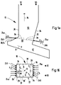
- 1a to 4a are of a waste incineration plant each a section of a flue gas outlet 10 and a combustion chamber 12 and a transition area 20 between Combustion chamber 12 and flue gas outlet 10 with a flame blanket 14 shown in section along the flue gas outlet 10.
- Flue gas mixtures is a rectangular flow channel 18 provided that the transition region 20 from the Combustion chamber 12 for the flue gas outlet 10 and the flue gas outlet 10 includes.
- the basic flow direction of the Flue gas mixture is indicated by an arrow 16.
- 1b to 4b are cross-sections to Flow channel 18 shown in the area of an injection plane 22, in which nozzle 24 for injecting sprayable media are arranged.
- the nozzles 24 and their orientation are in all representations represented by arrows.
- the direction of waste flow is indicated by an arrow 9.
- All of the embodiments shown in FIGS. 1 a to 4 b have first wall sections 28 with a length l 1 of at least approximately 40% to 80% of the wall width b of a wall 26 on at least two walls 26 lying opposite one another.
- the first wall sections 28 lie with the central longitudinal axis 32 of the flow channel 18 as a symmetrical axis of symmetry with respect to one another and are delimited on one side by the adjacent wall 26.
- First nozzles 24a are arranged in a row in an injection plane 22 in the first wall sections 28, which are opposite one another in a point-symmetrical manner.
- the first nozzles 24a are aligned in the injection plane 22 so that they inject into it, the angle ⁇ lying in the injection plane between the injected jet 30 and the wall 26 being approximately 90 °. This arrangement of nozzles 24 enables thorough mixing of the flue gas mixture which is excited to rotate in the flow channel 18 and flows in the direction 16.
- the injection plane 22 lies in the area of the flame blanket 14, which is arranged in the transition area 20 between the flue gas outlet 10 and the combustion chamber 12.
- the flame blanket 14 is either itself penetrated by nozzles 24, as shown in all four examples, and / or it is via nozzles 24a ', 24b'', which are arranged in walls (26) laterally below the flame blanket (14), with sprayable media 2 to 4, as shown in FIGS. 2 to 4. In this way, the flame blanket 14 can be cooled by the injected media.
- first wall sections 28 with a length l 1 of approximately 40% to 50% of the wall width b are provided on two mutually opposite walls 26.
- second wall section 34 of length l 2 in addition to the row of the first nozzles 24a in the first wall section 28, there are second nozzles 24b which are oriented at an angle ⁇ with respect to the first nozzles 24a obliquely towards the center of the flow channel 18 represented by the central longitudinal axis 32 are.
- the angle ⁇ is about 25 ° in this example, but it can be between 20 ° and 50 °.
- the lengths l 1 and l 2 of the two wall sections 28, 34 add up to the entire wall width b in this example, but this need not necessarily be the case.
- the second nozzles 24b are aligned in a common plane 36 which is tilted by the angle ⁇ relative to the injection plane 22.
- the angle ⁇ is about 10 ° in this example, but can vary and be between 5 ° and 15 °.
- the second nozzles 24b are aligned in such a way that the jets 30 generated by them flow helically into one another.
- the second nozzles 24b can also be tilted with individual angles ⁇ relative to the injection plane 22.
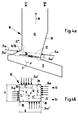
- FIGS. 2a to 2c An embodiment is shown in which on all four walls 26 of the Flow channel 18 first nozzles 24a in a first Wall section 28 and second nozzles 24b in a second Wall section 34 analogous to that in FIGS. 1a and 1b illustrated embodiment are arranged.
- the first Wall sections 28 are opposed in the circumferential direction of the rotating flow at the beginning of a wall 26 arranged.
- the nozzles 24a, 24b and 24a ', 24a' ', 24b', 24b '' are parallel in two, in the direction of flow spaced-apart injection planes 22 and 22 * arranged, with nozzles 24 on opposite one another Walls 26 in a common injection plane 22, 22 * are arranged.
- the distance d between the injection planes 22, 22 * can be between 0.4m and 3m.
- first wall sections 28 with first nozzles 24a are arranged in a single injection plane 22 on all four walls 26 of the flow channel 18.
- the length l 1 of the first wall sections 28 is well above 0.5b, preferably 0.55b to 0.75b.
- the rest of each wall 26 remaining over the entire wall width b is free of nozzles 24.
- This arrangement and alignment of the first nozzles 24a make it possible to jet 30 into the center of the generated rotating flow, so that a complete mixing of the flue gas mixture takes place .
- the nozzles 24a instead of in one single injection level 22 (see. Fig. 3a, 3b) in two to arrange parallel injection planes 22 and 22 * as shown in Figures 4a, 4b.
- All nozzles are designed so that media to be injected with a pressure of 500 Pa to 5000 Pa can be injected.
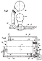
- annular gap nozzle 24 * is shown as it for example for injecting fresh secondary air and recirculated flue gas is provided.
- first feed line 40 for supplying a first Medium, in this case recirculated flue gas, into one trained as a core nozzle 42 and a core jet producing nozzle part and a second feed line 44 for the supply of a second medium, in this case fresh secondary air, in an annular gap 46 trained and producing a ring beam Nozzle part.
- a control system 48 Via a control system 48, as shown in FIG. 6 for Annular gap nozzles 24 * is shown, the different conditions as they are on different Sides of the flow channel 18 can prevail, better Be taken into account.
- the throughputs of the Media to be injected are via the control system 48 and the valves 54 in the example shown for the regarding Waste flow 9 upstream half 52 and the Half 50 of the flow channel 18 located downstream independently controllable.
- nozzles 24 for secondary air and nozzles 24 for recirculated flue gas are preferably provided. These nozzles 24 can either be arranged mixed in a row next to one another or also in two rows one above the other, so that there is a separate injection plane 22 for each nozzle type 24. If annular gap nozzles 24 * are provided, the core jet consists of flue gas and the ring jet consists of secondary air, as described for FIG. 5.
- the device also in incinerators and Use waste incineration plants where the Transition area 20 between combustion chamber 12 and Flue gas discharge 10 characterized by a constriction is.
- Further injection levels 22 can also be located deeper in the Combustion chamber 12 or further up in the flue gas outlet 10 be provided.
- flue gas and Secondary air can also use other media such as water vapor Activated carbon, hearth coke (HOK), waste z. B. in the frame a recycling of residues, fuels etc. injected become.
- the device can be used.
- In the same Direction of rotation like the first nozzles 24a can burners 2m to 3m above the injection level 22 at two each other opposite walls 26 may be arranged.
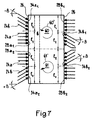
- FIG. 7 shows a further embodiment of the device according to the invention, in which two vortices 60 ', 61' rotating in opposite directions are generated.
- the device emerges from the device shown in FIG. 2b by reflection on the lower wall 26, ie the first and second nozzles shown there are doubled.
- the walls 26 of the device each have two first wall sections 28a1 and 28a2 or 28b1 and 28b2 with first nozzles 24a.
- the first nozzles 24a of the first wall sections 28a2, 28b2 in the lower half of the cross section are arranged obliquely opposite one another and produce a clockwise rotating vortex 61 '. This is reinforced by the second nozzles 24b of the second wall areas 34a2, 34b2.
- the second nozzles 24b radiate in a direction which is offset by +/- ⁇ from the jet direction of the first nozzles.
- These second wall areas 34a2, 34b2 are also diagonally opposite one another.
- the wall areas in the lower half of the cross section shown define a first swirl area 61.
- a second swirl area 60 is defined by the first and second wall sections 28a1, 28b1, 34a1, 34b1 in the upper part of FIG.
- the second vortex 60 'there rotates counterclockwise.
- the first wall sections 28a1, 28a2, 28b1, 28b2 each have a length l 1 .
- the first wall sections 28a1 and 28b1 (second vertebra 60 ') or 28a2 and 28b2 (second vertebra 61') lying diagonally opposite one another determine the direction of rotation of the vertebra 60 ', 61'.
- the second nozzles 24b then jet in such a way that they intensify the rotation, ie tangentially in the direction of rotation to an imaginary circle around the center of the vortex 60 'or 61'.
Landscapes
- Engineering & Computer Science (AREA)
- Mechanical Engineering (AREA)
- General Engineering & Computer Science (AREA)
- Chemical & Material Sciences (AREA)
- Combustion & Propulsion (AREA)
- Chemical Kinetics & Catalysis (AREA)
- General Chemical & Material Sciences (AREA)
- Incineration Of Waste (AREA)
- Chimneys And Flues (AREA)
Abstract
Description
- Fig. 1a, b
- eine erste Ausführungsform der erfindungsgemässen Vorrichtung mit an zwei einander gegenüberliegenden Wänden eines rechteckigen Strömungskanals angeordneten ersten Düsen und zweiten Düsen, wobei Fig. 1a den Schnitt längs des Strömungskanals und Fig. 1b einen Schnitt quer zum Strömungskanal zeigt;
- Fig. 2a, b, c
- eine zweite Ausführungsform der Vorrichtung mit einer Anordnung der Düsen analog derjenigen aus den Fig. 1a und 1b, wobei jedoch an den anderen zwei Wänden des rechteckigen Strömungskanals ebenfalls Düsen angeordnet sind und zwar in einer zweiten, zur ersten Eindüsebene in Strömungsrichtung beabstandeten, parallelen Eindüsebene und die Darstellung in Fig. 2a analog zu der aus Fig. 1a und die Darstellungen in den Fig. 2b und 2c analog derjenigen aus 1b sind.;
- Fig. 3a, b
- eine dritte Ausführungsform der Vorrichtung mit ersten Düsen an allen vier Wänden des rechteckigen Strömungskanals in einer Eindüsebene mit Darstellung analog den Fig. 1a und 1b;
- Fig. 4a, b,
- eine vierte Ausführungsform der Vorrichtung mit ersten Düsen an allen vier Wänden des rechteckigen Strömungskanals, wobei die Düsen in zwei voneinander in Strömungsrichtung beabstandete, parallelen Eindüsebenen verteilt sind und zwar jeweils einander gegenüberliegende erste Düsen in einer Eindüsebene und mit Darstellung analog den Fig. 1a und 1b;
- Fig. 5
- ein Beispiel für eine Ringspaltdüse;
- Fig. 6
- ein Steuerungssystem für die getrennte Steuerung der Durchsatzmenge für an verschiedenen Wänden angeordnete Düsen;
- Fig. 7
- eine weitere Ausführungsform der Vorrichtung zur Erzeugung von wenigstens zwei gegenläufig rotierenden Wirbeln.
Claims (16)
- Vorrichtung zur Erzeugung einer rotierenden Strömung in einem rechteckigen Strömungskanal (18), der einen Rauchgasabzug (10) einer Verbrennungsanlage, insbesondere einer Müllverbrennungsanlage, umfasst, mit mehreren in einer Eindüsebene (22) an zwei einander gegenüberliegenden, den Strömungskanal (18) begrenzenden Wänden (26) mit Wandbreite b angeordneten Düsen (24) für verdüsbare Medien, dadurch gekennzeichnet, dass der Strömungskanal (18) einen Übergangsbereich (20) von einer Brennkammer (12) der Verbrennungsanlage zum Rauchgasabzug (10) umfasst und dass jeweils in wenigstens einem ersten Wandabschnitt (28, 28a1, 28a2, 28b1, 28b2) der beiden einander gegenüberliegenden Wände (26) erste Düsen (24a) in einer Reihe derart ausgerichtet sind, dass sie in die Eindüsebene (22) eindüsen und der in der Eindüsebene (22) liegende Winkel γ zwischen der Wand (26) und einem eingedüsten Strahl (30) wenigstens annähernd 90° beträgt, wobei die Summe L der Längen l der ersten Wandabschnitte (28, 28a1, 28a2, 28b1, 28b2) wenigstens annähernd 0.4b < L < 0.8b beträgt und der wenigstens eine erste Wandabschnitt (28, 28a1, 28a2) der einen Wand dem wenigstens einen ersten Wandabschnitt (28, 28b1, 28b2) der gegenüberliegenden Wand schräg gegenüberliegt.
- Vorrichtung nach Anspruch 1, dadurch gekennzeichnet, dass die gegenüberliegenden Wände jeweils einen ersten Wandabschnitt (28) aufweisen, die mit der Mittellängsachse (32) des Strömungskanals (18) als Symmetrieachse einander punktsymmetrisch gegenüberliegen und auf einer Seite durch die benachbarte Wand (26) begrenzt werden.
- Vorrichtung nach Anspruch 1 oder 2, dadurch gekennzeichnet, dass jeweils in der Eindüsebene (22) in wenigstens einem zweiten Wandabschnitt (34, 34a1, 34a2, 34b1, 34b2) der beiden gegenüberliegenden Wände (26) zweite Düsen (24b) angeordnet sind, wobei für den in der Eindüsebene liegenden Winkel β zwischen den von den ersten und den zweiten Düsen (24a, 24b) eingedüsten Strahlen gilt, dass |β|> 0° ist, vorzugsweise 20°<|β|<50°, und vorzugsweise der wenigstens eine zweite Wandabschnitt (34, 34a1, 34a2, 34b1, 34b2) der einen Wand dem wenigstens einen zweiten Wandabschnitt (34, 34a1, 34a2, 34b1, 34b2) der gegenüberliegenden Wand schräg gegenüberliegt.
- Vorrichtung nach Anspruch 3, dadurch gekennzeichnet, dass zur Erzeugung von einem rotierenden Wirbel jede der beiden gegenüberliegenden Wände einen ersten (28) und einen zweiten Wandabschnitt (34) aufweist und die ersten und die zweiten Wandabschnitte mit der Mittellängsachse (32) des Strömungskanals (18) als Symmetrieachse einander jeweils punktsymmetrisch gegenüberliegen und auf einer Seite durch die benachbarte Wand (26') begrenzt werden.
- Vorrichtung nach einem der Ansprüche 1 bis 3, dadurch gekennzeichnet, dass zur Erzeugung von wenigstens zwei gegenläufig rotierenden Wirbeln jede der beiden gegenüberliegenden Wände wenigstens zwei erste Wandabschnitte (28, 28a1, 28a2, 28b1, 28b2) aufweist.
- Vorrichtung nach Anspruch 5, dadurch gekennzeichnet, dass jede der beiden gegenüberliegenden Wände zusätzlich zwei zweite Wandabschnitte aufweist, wobei jeweils ein erster (28a1, 28a2) und ein zweiter (34a1, 34a2) Wandabschnitt der einen Wand mit den direkt gegenüberliegenden zweiten (34b1, 34b2) bzw. ersten (28b1, 28b2) Wandabschnitten der gegenüberliegenden Wand einen Wirbelbereich (60, 61) bilden und wobei die von den zweiten Düsen (24b) eingedüsten Strahlen in einem ersten Wirbelbereich (61) um +|β| und in einem zweiten Wirbelbereich (60) um -|β| gegen die von den ersten Düsen (24a) eingedüsten Strahlen geneigt sind.
- Vorrichtung nach einem der Ansprüche 3 bis 6, dadurch gekennzeichnet, dass die zweiten Düsen (24b) des zweiten Wandabschnittes (34) mit einer Eindüskomponente in einem Winkel α, der vorzugsweise zwischen 5° und 15° liegt, bezüglich der Eindüsebene (22) und vorzugsweise in eine gemeinsamen Ebene (36) in Richtung der Strömung im Strömungskanal (18) ausgerichtet sind.
- Vorrichtung nach einem der vorangegangenen Ansprüche, dadurch gekennzeichnet, dass alle vier Wände (26) des Strömungskanals (18) einen ersten Wandabschnitt (28) mit ersten Düsen (24a) aufweisen, wobei die ersten Wandabschnitte (28) in Umfangsrichtung entgegen der rotierenden Strömung jeweils am Beginn einer Wand (26) und vom ersten Wandabschnitt (28) der benachbarten Wand (26) beabstandet angeordnet sind.
- Vorrichtung nach Anspruch 8, dadurch gekennzeichnet, dass die Düsen (24) aller vier Wände (26) in derselben Eindüsebene (22) liegen.
- Vorrichtung nach Anspruch 8, dadurch gekennzeichnet, dass die Düsen (24) in zwei parallelen, in Strömungsrichtung voneinander beabstandeten Eindüsebenen (22, 22*) angeordnet sind, wobei einander gegenüberliegende Düsen in der selben Eindüsebene (22, 22*) liegen.
- Vorrichtung nach einem der Ansprüche 5 oder 6, dadurch gekennzeichnet, dass einander schräg bzw. punktsymmetrisch gegenüberliegende Wandabschnitte (28, 34) annähernd die gleiche Länge 1 aufweisen.
- Vorrichtung nach einem der vorangegangenen Ansprüche, dadurch gekennzeichnet, dass der Speisedruck mit dem die verdüsbaren Medien in die Düsen gelangen zwischen 500Pa und 5000Pa liegt und dass mittels eines Steuerungssystems (48) die Durchsatzmenge für an verschiedenen Wänden (26) angeordnete Düsen (24) vorzugsweise unabhängig voneinander steuerbar ist.
- Vorrichtung nach einem der vorangegangenen Ansprüche, dadurch gekennzeichnet, dass als Düsen (24) Ringspaltdüsen (24*) vorgesehen sind.
- Vorrichtung nach einem der vorangegangenen Ansprüche, dadurch gekennzeichnet, dass Düsen (24) zum Verdüsen von Sekundärluft und rezirkuliertem Rauchgas vorgesehen sind.
- Vorrichtung nach Anspruch 9 und 10, dadurch gekennzeichnet, dass der Kernstrahl der Ringspaltdüsen aus rezirkuliertem Rauchgas und der Ringstrahl aus Sekundärluft besteht.
- Vorrichtung nach einem der vorangegangenen Ansprüche, dadurch gekennzeichnet, dass wenigstens eine Eindüsebene (22) im Bereich einer im Übergangsbereich (20) angeordneten Flammdecke (14) liegt, so dass die Flammdecke (14) entweder von Düsen (24, 38) durchsetzt ist und/oder die Düsen (24, 38) in Wänden (26) seitlich unterhalb der Flammdecke (14) so angeordnet sind, dass sie die Flammdecke (14) eindüsend kühlen.
Applications Claiming Priority (2)
| Application Number | Priority Date | Filing Date | Title |
|---|---|---|---|
| CH158599 | 1999-08-30 | ||
| CH01585/99A CH694305A5 (de) | 1999-08-30 | 1999-08-30 | Vorrichtung zur Erzeugung einer rotierenden Stroemung. |
Publications (3)
| Publication Number | Publication Date |
|---|---|
| EP1081434A1 true EP1081434A1 (de) | 2001-03-07 |
| EP1081434B1 EP1081434B1 (de) | 2004-10-13 |
| EP1081434B2 EP1081434B2 (de) | 2008-12-31 |
Family
ID=4213860
Family Applications (1)
| Application Number | Title | Priority Date | Filing Date |
|---|---|---|---|
| EP00117240A Expired - Lifetime EP1081434B2 (de) | 1999-08-30 | 2000-08-14 | Vorrichtung zur Erzeugung einer rotierenden Strömung |
Country Status (8)
| Country | Link |
|---|---|
| US (1) | US6938561B1 (de) |
| EP (1) | EP1081434B2 (de) |
| JP (1) | JP3750014B2 (de) |
| KR (1) | KR100465934B1 (de) |
| CH (1) | CH694305A5 (de) |
| CZ (1) | CZ297291B6 (de) |
| DE (1) | DE50008206D1 (de) |
| TW (1) | TW454082B (de) |
Cited By (4)
| Publication number | Priority date | Publication date | Assignee | Title |
|---|---|---|---|---|
| WO2003083370A1 (en) * | 2002-04-03 | 2003-10-09 | Seghers Keppel Technology Group Nv | Method and device for controlling injection of primary and secondary air in an incineration system |
| EP1319894A3 (de) * | 2001-12-11 | 2003-11-26 | Fritz Dr.-Ing. Schoppe | Verfahren zum Verbrennen von Abfällen und Vorrichtung zum Behandeln der Abgase einer Abfallverbrennung |
| EP2505919A1 (de) * | 2011-03-29 | 2012-10-03 | Hitachi Zosen Inova AG | Verfahren zur Optimierung des Ausbrands von Abgasen einer Verbrennungsanlage durch Homogenisierung der Abgase über dem Brennbett mittels Abgas-Einspritzung |
| DE102016002899A1 (de) * | 2016-03-09 | 2017-09-14 | Johannes Kraus | (Naturzug)Feuerraum mit verbessertem Ausbrand |
Families Citing this family (11)
| Publication number | Priority date | Publication date | Assignee | Title |
|---|---|---|---|---|
| AU2003203838B2 (en) * | 2002-04-26 | 2008-02-07 | Le Mac Australia Holdings Pty Ltd | Shrink sleeve |
| KR100657147B1 (ko) * | 2004-12-08 | 2006-12-12 | 두산중공업 주식회사 | 공해 물질 저감을 위한 혼합 촉진구조 및 이를 이용한혼합촉진방법 |
| FR2910113B1 (fr) * | 2006-12-14 | 2009-02-13 | Veolia Proprete Sa | Four d'incineration a recuperation d'energie optimisee |
| US20090151609A1 (en) * | 2007-12-15 | 2009-06-18 | Hoskinson Gordon H | Incinerator with pivoting grating system |
| KR100903778B1 (ko) * | 2008-12-03 | 2009-06-19 | 한국기계연구원 | 순산소석탄연소 로내고온탈황용 석회석 평면분사장치 |
| KR101032608B1 (ko) * | 2010-11-30 | 2011-05-06 | 현대건설주식회사 | 유기성 폐기물 처리장치 |
| JP2015068517A (ja) * | 2013-09-27 | 2015-04-13 | 日立造船株式会社 | 焼却炉における燃焼運転方法および焼却炉 |
| JP6797084B2 (ja) * | 2017-06-27 | 2020-12-09 | 川崎重工業株式会社 | 二次燃焼用気体供給方法、二次燃焼用気体供給構造、及び廃棄物焼却炉 |
| CN109405276B (zh) * | 2018-09-30 | 2021-07-27 | 农业部规划设计研究院 | 一种秸秆捆烧锅炉清洁供暖系统 |
| JP6620213B2 (ja) * | 2018-11-28 | 2019-12-11 | 株式会社神鋼環境ソリューション | 二次燃焼設備 |
| WO2025228764A1 (en) | 2024-04-29 | 2025-11-06 | Kanadevia Inova Ag | Waste incineration plant and method for operating the same |
Citations (4)
| Publication number | Priority date | Publication date | Assignee | Title |
|---|---|---|---|---|
| US5252298A (en) * | 1991-04-23 | 1993-10-12 | Noell, Inc. | Device for cleaning gases |
| WO1995035409A1 (en) * | 1994-06-20 | 1995-12-28 | Kvaerner Pulping Ab | Recovery boiler with rotating secondary air below and a constriction above the level at which the liquor is injected |
| DE19648639A1 (de) * | 1996-10-10 | 1998-04-23 | Steinmueller Gmbh L & C | Verfahren zum Verbrennen von Brennstoff auf einem Rost und Rostfeuerung zur Durchführung des Verfahrens |
| DE19705938A1 (de) * | 1997-02-17 | 1998-08-20 | Abb Research Ltd | Verfahren zum Eindüsen von Sekundärluft und/oder Tertiärluft sowie von rezirkulierenden Rauchgasen in einem Kessel sowie Vorrichtung zur Durchführung des Verfahrens |
Family Cites Families (17)
| Publication number | Priority date | Publication date | Assignee | Title |
|---|---|---|---|---|
| US3788796A (en) * | 1973-05-09 | 1974-01-29 | Babcock & Wilcox Co | Fuel burner |
| JPS55105104A (en) | 1979-02-07 | 1980-08-12 | Babcock Hitachi Kk | Low-nox burner |
| JPS5893609U (ja) * | 1981-12-18 | 1983-06-24 | 三菱重工業株式会社 | 燃料ガスの燃焼装置 |
| US4570551A (en) * | 1984-03-09 | 1986-02-18 | International Coal Refining Company | Firing of pulverized solvent refined coal |
| JPS6218802A (ja) | 1985-07-18 | 1987-01-27 | Mitsubishi Electric Corp | 円偏波ホ−ンアンテナ装置 |
| DE3531571A1 (de) * | 1985-09-04 | 1987-03-05 | Steinmueller Gmbh L & C | Verfahren zum verfeuern von brennstoffen unter reduzierung der stickoxidbelastung und feuerung zur durchfuehrung des verfahrens |
| US5020456A (en) * | 1990-02-28 | 1991-06-04 | Institute Of Gas Technology | Process and apparatus for emissions reduction from waste incineration |
| JPH076621B2 (ja) | 1990-06-21 | 1995-01-30 | 株式会社クボタ | 焼却炉の二次空気吹込み方法 |
| US5078064B1 (en) * | 1990-12-07 | 1999-05-18 | Gas Res Inst | Apparatus and method of lowering no emissions using diffusion processes |
| JPH0526421A (ja) * | 1991-07-19 | 1993-02-02 | Sanki Eng Co Ltd | ごみ焼却炉のごみ燃焼方法 |
| JP2758090B2 (ja) * | 1991-10-21 | 1998-05-25 | 株式会社クボタ | 焼却炉におけるco制御方法 |
| JPH06272836A (ja) * | 1993-03-22 | 1994-09-27 | Takuma Co Ltd | 焼却炉におけるco低減方法 |
| JP3383959B2 (ja) | 1993-10-07 | 2003-03-10 | 三機工業株式会社 | ごみ焼却炉のごみ燃焼方法及びその装置 |
| JPH10205734A (ja) | 1997-01-14 | 1998-08-04 | Takuma Co Ltd | ストーカ式燃焼炉における2次空気の供給方法 |
| JPH10288325A (ja) | 1997-04-16 | 1998-10-27 | N K K Plant Kensetsu Kk | ごみ焼却炉燃焼排ガス中のダイオキシン類発生抑制方法 |
| JPH1151367A (ja) | 1997-08-01 | 1999-02-26 | Suzuki Tsutomu | 焼却炉の燃焼方法、及び焼却炉の燃焼室構造 |
| DE19939672B4 (de) † | 1999-08-20 | 2005-08-25 | Alstom Power Boiler Gmbh | Feuerungssystem sowie Verfahren zur Wärmeerzeugung durch Verbrennung |
-
1999
- 1999-08-30 CH CH01585/99A patent/CH694305A5/de not_active IP Right Cessation
-
2000
- 2000-08-02 TW TW089115525A patent/TW454082B/zh not_active IP Right Cessation
- 2000-08-14 EP EP00117240A patent/EP1081434B2/de not_active Expired - Lifetime
- 2000-08-14 DE DE2000508206 patent/DE50008206D1/de not_active Expired - Lifetime
- 2000-08-29 KR KR10-2000-0050424A patent/KR100465934B1/ko not_active Expired - Fee Related
- 2000-08-30 US US09/650,533 patent/US6938561B1/en not_active Expired - Lifetime
- 2000-08-30 CZ CZ20003153A patent/CZ297291B6/cs not_active IP Right Cessation
- 2000-08-30 JP JP2000260826A patent/JP3750014B2/ja not_active Expired - Lifetime
Patent Citations (4)
| Publication number | Priority date | Publication date | Assignee | Title |
|---|---|---|---|---|
| US5252298A (en) * | 1991-04-23 | 1993-10-12 | Noell, Inc. | Device for cleaning gases |
| WO1995035409A1 (en) * | 1994-06-20 | 1995-12-28 | Kvaerner Pulping Ab | Recovery boiler with rotating secondary air below and a constriction above the level at which the liquor is injected |
| DE19648639A1 (de) * | 1996-10-10 | 1998-04-23 | Steinmueller Gmbh L & C | Verfahren zum Verbrennen von Brennstoff auf einem Rost und Rostfeuerung zur Durchführung des Verfahrens |
| DE19705938A1 (de) * | 1997-02-17 | 1998-08-20 | Abb Research Ltd | Verfahren zum Eindüsen von Sekundärluft und/oder Tertiärluft sowie von rezirkulierenden Rauchgasen in einem Kessel sowie Vorrichtung zur Durchführung des Verfahrens |
Cited By (10)
| Publication number | Priority date | Publication date | Assignee | Title |
|---|---|---|---|---|
| EP1319894A3 (de) * | 2001-12-11 | 2003-11-26 | Fritz Dr.-Ing. Schoppe | Verfahren zum Verbrennen von Abfällen und Vorrichtung zum Behandeln der Abgase einer Abfallverbrennung |
| WO2003083370A1 (en) * | 2002-04-03 | 2003-10-09 | Seghers Keppel Technology Group Nv | Method and device for controlling injection of primary and secondary air in an incineration system |
| EP1726877A1 (de) * | 2002-04-03 | 2006-11-29 | Keppel Seghers Holdings Pte Ltd | Verfahren und vorrichtung zur regelung der primär- und sekundärlufteinspritzung einer müllverbrennungsanlage |
| CN100402925C (zh) * | 2002-04-03 | 2008-07-16 | 吉宝西格斯控股私人有限公司 | 焚烧固体材料的方法和装置 |
| EP2505919A1 (de) * | 2011-03-29 | 2012-10-03 | Hitachi Zosen Inova AG | Verfahren zur Optimierung des Ausbrands von Abgasen einer Verbrennungsanlage durch Homogenisierung der Abgase über dem Brennbett mittels Abgas-Einspritzung |
| WO2012130446A1 (de) | 2011-03-29 | 2012-10-04 | Hitachi Zosen Inova Ag | Verfahren zur optimierung des ausbrands von abgasen einer verbrennungsanlage |
| EP2691701B1 (de) | 2011-03-29 | 2017-08-23 | Hitachi Zosen Inova AG | Verfahren zur optimierung des ausbrands von abgasen einer verbrennungsanlage |
| EP2691701B2 (de) † | 2011-03-29 | 2024-03-20 | Hitachi Zosen Inova AG | Verfahren zur optimierung des ausbrands von abgasen einer verbrennungsanlage |
| DE102016002899A1 (de) * | 2016-03-09 | 2017-09-14 | Johannes Kraus | (Naturzug)Feuerraum mit verbessertem Ausbrand |
| DE102016002899B4 (de) * | 2016-03-09 | 2020-03-12 | Johannes Kraus | Feuerraum mit verbessertem Ausbrand |
Also Published As
| Publication number | Publication date |
|---|---|
| JP2001099415A (ja) | 2001-04-13 |
| EP1081434B1 (de) | 2004-10-13 |
| JP3750014B2 (ja) | 2006-03-01 |
| TW454082B (en) | 2001-09-11 |
| CZ20003153A3 (cs) | 2001-08-15 |
| KR20010050249A (ko) | 2001-06-15 |
| EP1081434B2 (de) | 2008-12-31 |
| DE50008206D1 (de) | 2004-11-18 |
| KR100465934B1 (ko) | 2005-01-13 |
| CZ297291B6 (cs) | 2006-10-11 |
| CH694305A5 (de) | 2004-11-15 |
| US6938561B1 (en) | 2005-09-06 |
Similar Documents
| Publication | Publication Date | Title |
|---|---|---|
| DE69412484T2 (de) | Verbrennungskammer eines gasturbinenmotors | |
| EP0433790B1 (de) | Brenner | |
| DE4426351B4 (de) | Brennkammer für eine Gasturbine | |
| EP0436113B1 (de) | Verfahren zum Betrieb einer Feuerungsanlage | |
| EP1081434B1 (de) | Vorrichtung zur Erzeugung einer rotierenden Strömung | |
| EP0392158B1 (de) | Verfahren zum Betrieb einer Feuerungsanlage mit fossilen Brennstoffen | |
| CH680084A5 (de) | ||
| EP0718561A2 (de) | Brennkammer | |
| EP0724114A2 (de) | Brenner | |
| EP0629817A2 (de) | Feuerungsanlage | |
| DE4330083A1 (de) | Verfahren zum Betrieb eines Vormischbrenners | |
| EP0394800B1 (de) | Vormischbrenner für die Heissgaserzeugung | |
| EP0742411B1 (de) | Luftzuströmung zu einer Vormischbrennkammer | |
| EP0394911A1 (de) | Feuerungsanlage | |
| EP0483554B1 (de) | Verfahren zur Minimierung der NOx-Emissionen aus einer Verbrennung | |
| EP0777082A2 (de) | Vormischbrenner | |
| DE3939197C3 (de) | Verfahren und Vorrichtung zur Minderung der Stickoxid-Konzentration im Abgasstrom von Verbrennungsprozessen | |
| EP0961905B1 (de) | Vorrichtung und verfahren zum verbrennen von brennstoff | |
| DE2932378A1 (de) | Brennkammer fuer gasturbinentriebwerke | |
| EP0829678B1 (de) | Kanalbrenner und Verfahren zum Aufheizen eines strömenden Gases | |
| EP0518072A1 (de) | Brenner zum Betrieb einer Brennkraftmaschine, einer Brennkammer einer Gasturbogruppe oder einer Feuerungsanlage | |
| EP1286115A1 (de) | Thermische Nachverbrennungsanlage | |
| DE19917662C2 (de) | Brenner für flüssigen und/oder gasförmigen Brennstoff | |
| EP0545114B1 (de) | Einrichtung für eine Prozesswärmeerzeugung | |
| EP0866269B1 (de) | Kesselanlage für eine Wärmeerzeugung |
Legal Events
| Date | Code | Title | Description |
|---|---|---|---|
| PUAI | Public reference made under article 153(3) epc to a published international application that has entered the european phase |
Free format text: ORIGINAL CODE: 0009012 |
|
| 17P | Request for examination filed |
Effective date: 20001212 |
|
| AK | Designated contracting states |
Kind code of ref document: A1 Designated state(s): CH DE FR IT LI NL SE |
|
| AX | Request for extension of the european patent |
Free format text: AL;LT;LV;MK;RO;SI |
|
| AKX | Designation fees paid |
Free format text: CH DE FR IT LI NL SE |
|
| 17Q | First examination report despatched |
Effective date: 20030811 |
|
| GRAP | Despatch of communication of intention to grant a patent |
Free format text: ORIGINAL CODE: EPIDOSNIGR1 |
|
| GRAS | Grant fee paid |
Free format text: ORIGINAL CODE: EPIDOSNIGR3 |
|
| GRAA | (expected) grant |
Free format text: ORIGINAL CODE: 0009210 |
|
| AK | Designated contracting states |
Kind code of ref document: B1 Designated state(s): CH DE FR IT LI NL SE |
|
| REG | Reference to a national code |
Ref country code: CH Ref legal event code: EP |
|
| REG | Reference to a national code |
Ref country code: CH Ref legal event code: NV Representative=s name: PATENTANWAELTE SCHAAD, BALASS, MENZL & PARTNER AG |
|
| REF | Corresponds to: |
Ref document number: 50008206 Country of ref document: DE Date of ref document: 20041118 Kind code of ref document: P |
|
| REG | Reference to a national code |
Ref country code: SE Ref legal event code: TRGR |
|
| PLBI | Opposition filed |
Free format text: ORIGINAL CODE: 0009260 |
|
| ET | Fr: translation filed | ||
| PLAX | Notice of opposition and request to file observation + time limit sent |
Free format text: ORIGINAL CODE: EPIDOSNOBS2 |
|
| 26 | Opposition filed |
Opponent name: ALSTOM POWER BOILER GMBH Effective date: 20050708 |
|
| NLR1 | Nl: opposition has been filed with the epo |
Opponent name: ALSTOM POWER BOILER GMBH |
|
| PLAF | Information modified related to communication of a notice of opposition and request to file observations + time limit |
Free format text: ORIGINAL CODE: EPIDOSCOBS2 |
|
| PLBB | Reply of patent proprietor to notice(s) of opposition received |
Free format text: ORIGINAL CODE: EPIDOSNOBS3 |
|
| REG | Reference to a national code |
Ref country code: SE Ref legal event code: RPEO |
|
| PUAH | Patent maintained in amended form |
Free format text: ORIGINAL CODE: 0009272 |
|
| STAA | Information on the status of an ep patent application or granted ep patent |
Free format text: STATUS: PATENT MAINTAINED AS AMENDED |
|
| 27A | Patent maintained in amended form |
Effective date: 20081231 |
|
| AK | Designated contracting states |
Kind code of ref document: B2 Designated state(s): CH DE FR IT LI NL SE |
|
| REG | Reference to a national code |
Ref country code: CH Ref legal event code: AEN Free format text: AUFRECHTERHALTUNG DES PATENTES IN GEAENDERTER FORM |
|
| NLR2 | Nl: decision of opposition |
Effective date: 20081231 |
|
| NLR3 | Nl: receipt of modified translations in the netherlands language after an opposition procedure | ||
| REG | Reference to a national code |
Ref country code: FR Ref legal event code: PLFP Year of fee payment: 17 |
|
| REG | Reference to a national code |
Ref country code: FR Ref legal event code: PLFP Year of fee payment: 18 |
|
| PGFP | Annual fee paid to national office [announced via postgrant information from national office to epo] |
Ref country code: CH Payment date: 20170727 Year of fee payment: 18 Ref country code: IT Payment date: 20170828 Year of fee payment: 18 |
|
| PGFP | Annual fee paid to national office [announced via postgrant information from national office to epo] |
Ref country code: SE Payment date: 20170821 Year of fee payment: 18 |
|
| REG | Reference to a national code |
Ref country code: FR Ref legal event code: PLFP Year of fee payment: 19 |
|
| REG | Reference to a national code |
Ref country code: CH Ref legal event code: PL |
|
| REG | Reference to a national code |
Ref country code: SE Ref legal event code: EUG |
|
| PG25 | Lapsed in a contracting state [announced via postgrant information from national office to epo] |
Ref country code: LI Free format text: LAPSE BECAUSE OF NON-PAYMENT OF DUE FEES Effective date: 20180831 Ref country code: CH Free format text: LAPSE BECAUSE OF NON-PAYMENT OF DUE FEES Effective date: 20180831 |
|
| PG25 | Lapsed in a contracting state [announced via postgrant information from national office to epo] |
Ref country code: SE Free format text: LAPSE BECAUSE OF NON-PAYMENT OF DUE FEES Effective date: 20180815 |
|
| PG25 | Lapsed in a contracting state [announced via postgrant information from national office to epo] |
Ref country code: IT Free format text: LAPSE BECAUSE OF NON-PAYMENT OF DUE FEES Effective date: 20180814 |
|
| PGFP | Annual fee paid to national office [announced via postgrant information from national office to epo] |
Ref country code: NL Payment date: 20190821 Year of fee payment: 20 |
|
| PGFP | Annual fee paid to national office [announced via postgrant information from national office to epo] |
Ref country code: DE Payment date: 20190822 Year of fee payment: 20 Ref country code: FR Payment date: 20190822 Year of fee payment: 20 |
|
| REG | Reference to a national code |
Ref country code: DE Ref legal event code: R071 Ref document number: 50008206 Country of ref document: DE |
|
| REG | Reference to a national code |
Ref country code: NL Ref legal event code: MK Effective date: 20200813 |