EP1081262A1 - Verfahren und Vorrichtung zur Herstellung von in Längsrichtung angeordneten Vliesstoffen - Google Patents
Verfahren und Vorrichtung zur Herstellung von in Längsrichtung angeordneten Vliesstoffen Download PDFInfo
- Publication number
- EP1081262A1 EP1081262A1 EP00402382A EP00402382A EP1081262A1 EP 1081262 A1 EP1081262 A1 EP 1081262A1 EP 00402382 A EP00402382 A EP 00402382A EP 00402382 A EP00402382 A EP 00402382A EP 1081262 A1 EP1081262 A1 EP 1081262A1
- Authority
- EP
- European Patent Office
- Prior art keywords
- air stream
- filaments
- speed air
- nonwoven fabric
- wall surface
- Prior art date
- Legal status (The legal status is an assumption and is not a legal conclusion. Google has not performed a legal analysis and makes no representation as to the accuracy of the status listed.)
- Granted
Links
- 239000004745 nonwoven fabric Substances 0.000 title claims abstract description 112
- 238000004519 manufacturing process Methods 0.000 title claims abstract description 36
- 238000000034 method Methods 0.000 title claims description 50
- 230000007246 mechanism Effects 0.000 claims abstract description 130
- 238000009987 spinning Methods 0.000 claims abstract description 29
- 230000000694 effects Effects 0.000 claims description 16
- 239000003595 mist Substances 0.000 claims description 8
- 238000001816 cooling Methods 0.000 claims description 7
- 230000002238 attenuated effect Effects 0.000 claims description 6
- 239000000463 material Substances 0.000 claims description 5
- 238000002844 melting Methods 0.000 claims description 4
- 230000008018 melting Effects 0.000 claims description 4
- 230000008569 process Effects 0.000 description 39
- 230000002093 peripheral effect Effects 0.000 description 22
- VZSRBBMJRBPUNF-UHFFFAOYSA-N 2-(2,3-dihydro-1H-inden-2-ylamino)-N-[3-oxo-3-(2,4,6,7-tetrahydrotriazolo[4,5-c]pyridin-5-yl)propyl]pyrimidine-5-carboxamide Chemical compound C1C(CC2=CC=CC=C12)NC1=NC=C(C=N1)C(=O)NCCC(N1CC2=C(CC1)NN=N2)=O VZSRBBMJRBPUNF-UHFFFAOYSA-N 0.000 description 12
- 239000007921 spray Substances 0.000 description 11
- 230000000052 comparative effect Effects 0.000 description 8
- 229920005989 resin Polymers 0.000 description 8
- 239000011347 resin Substances 0.000 description 8
- 239000000835 fiber Substances 0.000 description 7
- XLYOFNOQVPJJNP-UHFFFAOYSA-N water Substances O XLYOFNOQVPJJNP-UHFFFAOYSA-N 0.000 description 7
- 230000008859 change Effects 0.000 description 6
- -1 polyethylene Polymers 0.000 description 4
- 230000008901 benefit Effects 0.000 description 3
- 229920000642 polymer Polymers 0.000 description 3
- AFCARXCZXQIEQB-UHFFFAOYSA-N N-[3-oxo-3-(2,4,6,7-tetrahydrotriazolo[4,5-c]pyridin-5-yl)propyl]-2-[[3-(trifluoromethoxy)phenyl]methylamino]pyrimidine-5-carboxamide Chemical compound O=C(CCNC(=O)C=1C=NC(=NC=1)NCC1=CC(=CC=C1)OC(F)(F)F)N1CC2=C(CC1)NN=N2 AFCARXCZXQIEQB-UHFFFAOYSA-N 0.000 description 2
- 230000015572 biosynthetic process Effects 0.000 description 2
- 229920001971 elastomer Polymers 0.000 description 2
- 238000010438 heat treatment Methods 0.000 description 2
- 239000000314 lubricant Substances 0.000 description 2
- 229920000139 polyethylene terephthalate Polymers 0.000 description 2
- 239000005020 polyethylene terephthalate Substances 0.000 description 2
- MKYBYDHXWVHEJW-UHFFFAOYSA-N N-[1-oxo-1-(2,4,6,7-tetrahydrotriazolo[4,5-c]pyridin-5-yl)propan-2-yl]-2-[[3-(trifluoromethoxy)phenyl]methylamino]pyrimidine-5-carboxamide Chemical compound O=C(C(C)NC(=O)C=1C=NC(=NC=1)NCC1=CC(=CC=C1)OC(F)(F)F)N1CC2=C(CC1)NN=N2 MKYBYDHXWVHEJW-UHFFFAOYSA-N 0.000 description 1
- NIPNSKYNPDTRPC-UHFFFAOYSA-N N-[2-oxo-2-(2,4,6,7-tetrahydrotriazolo[4,5-c]pyridin-5-yl)ethyl]-2-[[3-(trifluoromethoxy)phenyl]methylamino]pyrimidine-5-carboxamide Chemical compound O=C(CNC(=O)C=1C=NC(=NC=1)NCC1=CC(=CC=C1)OC(F)(F)F)N1CC2=C(CC1)NN=N2 NIPNSKYNPDTRPC-UHFFFAOYSA-N 0.000 description 1
- 239000004952 Polyamide Substances 0.000 description 1
- 239000004698 Polyethylene Substances 0.000 description 1
- 239000004743 Polypropylene Substances 0.000 description 1
- 239000004372 Polyvinyl alcohol Substances 0.000 description 1
- 239000004820 Pressure-sensitive adhesive Substances 0.000 description 1
- 230000000903 blocking effect Effects 0.000 description 1
- 238000010924 continuous production Methods 0.000 description 1
- 238000000151 deposition Methods 0.000 description 1
- 238000010586 diagram Methods 0.000 description 1
- 230000005611 electricity Effects 0.000 description 1
- 238000004049 embossing Methods 0.000 description 1
- 239000004744 fabric Substances 0.000 description 1
- 239000010408 film Substances 0.000 description 1
- 239000012530 fluid Substances 0.000 description 1
- 229920002313 fluoropolymer Polymers 0.000 description 1
- 230000006872 improvement Effects 0.000 description 1
- 239000007788 liquid Substances 0.000 description 1
- 230000004048 modification Effects 0.000 description 1
- 238000012986 modification Methods 0.000 description 1
- 239000000123 paper Substances 0.000 description 1
- 229920006350 polyacrylonitrile resin Polymers 0.000 description 1
- 229920002647 polyamide Polymers 0.000 description 1
- 229920000728 polyester Polymers 0.000 description 1
- 229920000573 polyethylene Polymers 0.000 description 1
- 229920001155 polypropylene Polymers 0.000 description 1
- 229920002635 polyurethane Polymers 0.000 description 1
- 239000004814 polyurethane Substances 0.000 description 1
- 229920002451 polyvinyl alcohol Polymers 0.000 description 1
- 229920000915 polyvinyl chloride Polymers 0.000 description 1
- 239000004800 polyvinyl chloride Substances 0.000 description 1
- 230000005855 radiation Effects 0.000 description 1
- 230000003014 reinforcing effect Effects 0.000 description 1
- 238000005096 rolling process Methods 0.000 description 1
- 238000005070 sampling Methods 0.000 description 1
- 239000002904 solvent Substances 0.000 description 1
- 238000005507 spraying Methods 0.000 description 1
- 238000003892 spreading Methods 0.000 description 1
- 230000007480 spreading Effects 0.000 description 1
- 230000003068 static effect Effects 0.000 description 1
- 229920005992 thermoplastic resin Polymers 0.000 description 1
- 238000004804 winding Methods 0.000 description 1
Images


Classifications
-
- D—TEXTILES; PAPER
- D04—BRAIDING; LACE-MAKING; KNITTING; TRIMMINGS; NON-WOVEN FABRICS
- D04H—MAKING TEXTILE FABRICS, e.g. FROM FIBRES OR FILAMENTARY MATERIAL; FABRICS MADE BY SUCH PROCESSES OR APPARATUS, e.g. FELTS, NON-WOVEN FABRICS; COTTON-WOOL; WADDING ; NON-WOVEN FABRICS FROM STAPLE FIBRES, FILAMENTS OR YARNS, BONDED WITH AT LEAST ONE WEB-LIKE MATERIAL DURING THEIR CONSOLIDATION
- D04H3/00—Non-woven fabrics formed wholly or mainly of yarns or like filamentary material of substantial length
- D04H3/02—Non-woven fabrics formed wholly or mainly of yarns or like filamentary material of substantial length characterised by the method of forming fleeces or layers, e.g. reorientation of yarns or filaments
-
- D—TEXTILES; PAPER
- D04—BRAIDING; LACE-MAKING; KNITTING; TRIMMINGS; NON-WOVEN FABRICS
- D04H—MAKING TEXTILE FABRICS, e.g. FROM FIBRES OR FILAMENTARY MATERIAL; FABRICS MADE BY SUCH PROCESSES OR APPARATUS, e.g. FELTS, NON-WOVEN FABRICS; COTTON-WOOL; WADDING ; NON-WOVEN FABRICS FROM STAPLE FIBRES, FILAMENTS OR YARNS, BONDED WITH AT LEAST ONE WEB-LIKE MATERIAL DURING THEIR CONSOLIDATION
- D04H3/00—Non-woven fabrics formed wholly or mainly of yarns or like filamentary material of substantial length
- D04H3/08—Non-woven fabrics formed wholly or mainly of yarns or like filamentary material of substantial length characterised by the method of strengthening or consolidating
- D04H3/16—Non-woven fabrics formed wholly or mainly of yarns or like filamentary material of substantial length characterised by the method of strengthening or consolidating with bonds between thermoplastic filaments produced in association with filament formation, e.g. immediately following extrusion
-
- D—TEXTILES; PAPER
- D04—BRAIDING; LACE-MAKING; KNITTING; TRIMMINGS; NON-WOVEN FABRICS
- D04H—MAKING TEXTILE FABRICS, e.g. FROM FIBRES OR FILAMENTARY MATERIAL; FABRICS MADE BY SUCH PROCESSES OR APPARATUS, e.g. FELTS, NON-WOVEN FABRICS; COTTON-WOOL; WADDING ; NON-WOVEN FABRICS FROM STAPLE FIBRES, FILAMENTS OR YARNS, BONDED WITH AT LEAST ONE WEB-LIKE MATERIAL DURING THEIR CONSOLIDATION
- D04H3/00—Non-woven fabrics formed wholly or mainly of yarns or like filamentary material of substantial length
- D04H3/02—Non-woven fabrics formed wholly or mainly of yarns or like filamentary material of substantial length characterised by the method of forming fleeces or layers, e.g. reorientation of yarns or filaments
- D04H3/03—Non-woven fabrics formed wholly or mainly of yarns or like filamentary material of substantial length characterised by the method of forming fleeces or layers, e.g. reorientation of yarns or filaments at random
- D04H3/033—Non-woven fabrics formed wholly or mainly of yarns or like filamentary material of substantial length characterised by the method of forming fleeces or layers, e.g. reorientation of yarns or filaments at random reorientation immediately after yarn or filament formation
-
- D—TEXTILES; PAPER
- D04—BRAIDING; LACE-MAKING; KNITTING; TRIMMINGS; NON-WOVEN FABRICS
- D04H—MAKING TEXTILE FABRICS, e.g. FROM FIBRES OR FILAMENTARY MATERIAL; FABRICS MADE BY SUCH PROCESSES OR APPARATUS, e.g. FELTS, NON-WOVEN FABRICS; COTTON-WOOL; WADDING ; NON-WOVEN FABRICS FROM STAPLE FIBRES, FILAMENTS OR YARNS, BONDED WITH AT LEAST ONE WEB-LIKE MATERIAL DURING THEIR CONSOLIDATION
- D04H3/00—Non-woven fabrics formed wholly or mainly of yarns or like filamentary material of substantial length
- D04H3/02—Non-woven fabrics formed wholly or mainly of yarns or like filamentary material of substantial length characterised by the method of forming fleeces or layers, e.g. reorientation of yarns or filaments
- D04H3/04—Non-woven fabrics formed wholly or mainly of yarns or like filamentary material of substantial length characterised by the method of forming fleeces or layers, e.g. reorientation of yarns or filaments in rectilinear paths, e.g. crossing at right angles
Definitions
- the present invention relates to a nonwoven fabric of longitudinally aligned filaments, a nonwoven fabric produced by longitudinally stretching such a nonwoven fabric of longitudinally aligned filaments, and a method of and an apparatus for manufacturing such nonwoven fabrics.
- Nonwoven fabrics according to the present invention are excellent in mechanical strength and dimensional stability, and can be used as a material web for nonwoven fabrics that are strong in one direction and perpendicularly crossed nonwoven fabrics.
- Nonwoven fabrics manufactured by these processes are referred to as spunbonded nonwoven fabrics in a wide sense.
- the nonwoven fabrics manufactured by these processes are the mainstream of nonwoven fabrics as they are economical and mass-producible.
- the spunbonded nonwoven fabrics in a wide sense are randomly nonwoven fabrics in which filaments are randomly aligned. Many of those spunbonded nonwoven fabrics are of small mechanical strength and have no dimensional stability.
- the inventors of the present invention have devised a process of stretching a nonwoven fabric and a process of manufacturing a nonwoven fabric which comprise laminated perpendicularly crossed nonwoven fabrics in order to eliminate the drawbacks of conventional nonwoven fabrics (see Japanese patent publication No. 36948/92 and Japanese laid-open patent publication No. 204767/98 for details).
- Japanese patent publication No. 25541/84 discloses a process of aligning filaments in one direction by inclining a conveyor to the direction in which the filaments are ejected.
- Japanese laid-open patent publication No. 3604/95 reveals a process of depositing filaments ejected with an air stream on an air-permeable conveyor and controlling the air stream with an air stream blocking device disposed behind the conveyor for thereby spreading the filaments in the longitudinal direction to improve alignability of the filaments.
- Another object of the present invention is to provide a method of and an apparatus for manufacturing a longitudinally stretched nonwoven fabric by further stretching a longitudinally aligned nonwoven fabric longitudinally for increased mechanical strength.
- a method of manufacturing a longitudinally aligned nonwoven fabric comprises the steps of preparing a group of nozzles for extruding a plurality of filaments, and a conveyor for collecting and delivering the filaments extruded from the group of nozzles, carrying the filaments extruded from the group of nozzles with a high-speed air stream to attenuate the filaments, and periodically changing the direction of the high-speed air stream in the machine direction of the conveyor.
- An apparatus for manufacturing a longitudinally aligned nonwoven fabric comprises a spinning mechanism for extruding a plurality of filaments from nozzles, a high-speed air stream generating mechanism for generating a high-speed air stream to carry the filaments extruded from the nozzles to attenuate the filaments, a conveyor for collecting and delivering the filaments attenuated by the high-speed air stream, and at least one air stream vibrating mechanism for periodically changing the direction of the high-speed air stream in the machine direction of the conveyor.
- the filaments extruded from the nozzles are attenuated by the high-speed air stream and collected on the conveyor. Since the direction of the high-speed air stream is periodically changed in the machine direction of the conveyor, i.e., in the longitudinal direction, the filaments carried by the high-speed air stream are periodically vibrated in the longitudinal direction, and partially folded over themselves in the longitudinal direction as they are collected on the conveyor. As a consequence, a nonwoven fabric in which filaments are well aligned is produced.
- a spunbond process in a wide sense is employed because the spunbond process is the most refined spinning process and excellent both economically and for its mass-producibility.
- the spunbond process in the wide sense resides in that molten filaments, i.e., filaments molten with heat, rather than being dissolved in a solvent, are drafted at a high magnification and attenuated by a high-speed air stream whose speed is close to the sonic speed.
- the alignment of the filaments can be improved by periodically changing the direction of the high-speed air stream used to attenuate the filaments in the machine direction of the conveyor, and that the direction of the high-speed air stream can easily be changed based on the Coanda effect.
- an air stream vibrating mechanism is disposed in a region where the high-speed air stream flows, the air stream vibrating mechanism having a wall surface, at least one of the direction of the wall surface with respect to the direction of the high-speed air stream and the distance of the wall surface from the direction of the high-speed air stream being variable, or alternatively, an air stream vibrating mechanism is disposed which has a wall surface inclined to the direction of the high-speed air stream, the distance between the wall surface and the air stream axis of the high-speed air stream being variable.
- the filaments carried and attenuated by the high-speed air stream can be cooled before their molecules are aligned in the longitudinal direction.
- the nonwoven fabric when the nonwoven fabric is subsequently stretched in the longitudinal direction, the nonwoven fabric can be stretched to an increased extent.
- the method of manufacturing a longitudinally stretched nonwoven fabric comprises the steps of manufacturing a longitudinally aligned nonwoven fabric by the above method of manufacturing a longitudinally aligned nonwoven fabric, and longitudinally stretching the longitudinally aligned nonwoven fabric.
- the apparatus for manufacturing a longitudinally stretched nonwoven fabric comprises the above apparatus for manufacturing a longitudinally aligned nonwoven fabric, and a device for longitudinally stretching the longitudinally aligned nonwoven fabric manufactured by the apparatus for manufacturing a longitudinally aligned nonwoven fabric.
- the term "longitudinal direction” means the machine direction in which the nonwoven fabric is manufactured, i.e., the direction in which the nonwoven fabric is fed, and the term “transverse direction” means the direction perpendicular to the longitudinal direction, i.e., the direction transversely across the nonwoven fabric.
- a apparatus for manufacturing a nonwoven fabric having a spinning unit mainly comprising a melt-blow die 1 and a conveyor 7, and a stretching unit comprising a pair of stretching rollers 12a, 12b and pair of withdrawal nip rollers 16a, 16b.
- the melt-blow die 1 has a plurality of nozzles 3 in its lower distal end which are arrayed in a direction perpendicular to the sheet of Fig. 1.
- a molten resin 2 delivered from a gear pump (not shown) is extruded from the nozzles 3 to form a plurality of filaments 11.
- the melt-blow die 1 is shown in cross section for a better understanding of its internal structure, and only one of the nozzles 3 is illustrated.
- the melt-blow die 1 has a pair of air reservoirs 5a, 5b disposed one on each side of the nozzles 3.
- Air heated to a temperature equal to or higher than the melting point of the resin is introduced under pressure into the air reservoirs 5a, 5b, from which the air is ejected from slits 6a, 6b that communicate with the air reservoirs 5a, 5b and are open at the distal end of the melt-blow die 1.
- the high-speed air stream keeps the filaments 11 that are extruded from the nozzles 3 in a draftable molten state.
- the high-speed air stream applies frictional forces to the filaments 11 to draft the filaments 11 for thereby attenuating the filaments 11.
- the above mechanism is the same as the mechanism employed in the normal melt-blow process.
- the high-speed air stream has a temperature that is higher than the spinning temperature of the filaments 11 by 80°C or more, or preferably 120°C or more.
- the temperature of the filaments 11 immediately after they are extruded can be made sufficiently higher than the melting point of the filaments 11 by increasing the temperature of the high-speed air stream, the molecular orientation of the filaments 11 can be reduced.
- the conveyor 7 is disposed downwardly of the melt-blow die 1.
- the conveyor 7 is trained around a conveyor roller 13 that is rotatable by an actuator (not shown) and other rollers When the conveyor roller 13 is rotated about its own axis, the conveyor 7 is driven to deliver the filaments 11 extruded from the nozzles 3 to the right in Fig. 1.
- An air stream vibrating mechanism 9 in the form of a rotatable bar having an elliptic cross section is disposed in the vicinity of the melt-blow die 1 in a region where the high-speed air stream is produced from the slits 6a, 6b.
- the air stream vibrating mechanism 9 has a shaft 9a extending substantially perpendicularly to the direction in which the filaments 11 are fed on the conveyor 7, i.e., substantially parallel to the transverse direction of a nonwoven fabric to be manufactured.
- the shaft 9a is rotated about its own axis
- the air stream vibrating mechanism 9 is rotated about the shaft 9a in the direction indicated by the arrow A.
- the air stream vibrating mechanism 9 disposed in the region where the high-speed air stream flows is rotated, the direction in which the filaments 11 flow can be changed.
- the filaments 11 flow along the high-speed air stream which is a combined flow of the air ejected from the slits 6a, 6b.
- the high-speed air stream flows in a direction substantially perpendicular to the plane in which the filaments 11 are fed by the conveyor 7.
- the air stream vibrating mechanism 9 changes the direction of the flow of the filaments 11 based on the Coanda effect.
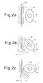
- the elliptic end of the air stream vibrating mechanism 9 has a major axis substantially parallel to the axis 10 of the high-speed air stream, and the air stream vibrating mechanism 9 has a peripheral wall surface 9b spaced from the air stream axis 10 by a maximum distance.
- the Coanda effect due to the peripheral wall surface 9b of the air stream vibrating mechanism 9 is minimum, and the high-speed air stream flows substantially along the air stream axis 10, and the filaments 11 also flow substantially along the air stream axis 10.
- the air stream vibrating mechanism 9 When the air stream vibrating mechanism 9 is turned about the shaft 9a to tilt the major axis 9c of the elliptic end of the air stream vibrating mechanism 9 with respect to the air stream axis 10, as shown in Fig. 2b, the distance between the peripheral wall surface 9b and the air stream axis 10 becomes progressively smaller, and the Coanda effect grows larger. Since the air stream vibrating mechanism 9 is in the form of a rotatable bar having an elliptic cross section, the distance between the peripheral wall surface 9b and the air stream axis 10 is progressively greater downstream in the direction of the high-speed air stream. Therefore, the high-speed air stream tends to flow along the peripheral wall surface 9b, attracting the filaments 11 toward the air stream vibrating mechanism 9.
- the air stream vibrating mechanism 9 When the air stream vibrating mechanism 9 is further turned about the shaft 9a to direct the major axis 9c perpendicularly to the air stream axis 10, as shown in Fig. 2c, the distance between the peripheral wall surface 9b and the air stream axis 10 becomes minimum. At this time, the Coanda effect is maximum. Downstream of the position where the peripheral wall surface 9b is closest to the air stream axis 10, the angle of the peripheral wall surface 9b with respect to the air stream axis 10 is greater than the angle shown in Fig. 2b. Consequently, the filaments 11 are more attracted toward the air stream vibrating mechanism 9 than they are in Fig. 2b.
- the filaments 11 can periodically be vibrated in the range shown in Figs. 2a through 2c. Since the shaft 9a of the air stream vibrating mechanism 9 extends substantially perpendicularly to the direction in which the filaments 11 are fed on the conveyor 7, the filaments 11 are vibrated in the direction in which the filaments 11 are fed on the conveyor 7, i.e., in their longitudinal direction.
- the air stream vibrating mechanism 9 rotates in the same direction as the flow of the filaments 11.
- the air stream vibrating mechanism 9 may rotate in the opposite direction to the flow of the filaments 11 insofar as the air stream vibrating mechanism 9 can periodically change the distance between the air stream and the peripheral wall surface 9b.
- the air stream vibrating mechanism may have its peripheral wall surface moved by vibration, rather than rotation.
- the width of the air stream vibrating mechanism 9, i.e., the length thereof parallel to the shaft 9a, should preferably be greater than the width of the group of filaments 11 produced by the melt-blow die 1 (see Fig. 1) by 100 mm or greater. If the width of the air stream vibrating mechanism 9 were smaller than the above size, then it would fail to sufficiently change the direction of the high-speed air stream at the opposite ends of the group of filaments 11, tending to longitudinally align the filaments 11 insufficiently at the opposite ends of the group of filaments 11.
- the minimum distance between the peripheral wall surface 9b and the air stream axis 10 is 25 mm or less, or preferably 15 mm or less. If the minimum distance between the air stream vibrating mechanism 9 and the air stream axis 10 were greater than the above distance, the effect of attracting the high-speed air stream to the air stream vibrating mechanism 9 would be too small to vibrate the filaments 11 sufficiently.
- the extent to which the filaments 11 are vibrated depends on the speed of the high-speed air stream and the rotational speed of the air stream vibrating mechanism 9. Specifically, if variations of the distance of the peripheral wall surface 9b of the air stream vibrating mechanism 9 from the air stream axis 10 of the high-speed air stream are considered to be vibrations of the peripheral wall surface 9b of the air stream vibrating mechanism 9, then there exists the particular frequency, of the peripheral wall surface 9b which makes maximum the extent to which the filaments 11 are vibrated. The particular number of vibrations differs depending on spinning conditions.
- the air stream vibrating mechanism 9 is rotated in order to maximize the extent to which the filaments 11 are vibrated.
- the speed of the high-speed air stream is 10 m/sec. or higher, or preferably 15 m/sec. or higher. If the speed of the high-speed air stream were smaller than the above value, the high-speed air stream would fail to be sufficiently attracted to the air stream vibrating mechanism 9, with the result that the filaments 11 would not sufficiently be vibrated.
- a spray nozzle 8 is disposed between the melt-blow die 1 and the conveyor 7.
- the spray nozzle 8 sprays a mist of water into the high-speed air stream to cool the filaments 11 to solidify the filaments 11 quickly. Only one spray nozzle 8 is illustrated though a plurality of spray nozzles 8 are employed.
- the solidified filaments 11 are stacked on the conveyor 7 while being vibrated in the longitudinal direction, and partially folded over themselves in the longitudinal direction and successively collected on the conveyor 7.
- the filaments 11 on the conveyor 7 are delivered to the right by the conveyor 7, nipped by the stretching roller 12a heated to a stretching temperature and a presser rollerl4, and transferred onto the stretching roller 12a. Thereafter, the filaments 11 are nipped by the stretching roller 12b and a presser rubber roller 15, and transferred onto the stretching roller 12b. The filaments 11 are now held in close contact with the stretching rollers 12a, 12b. Since the filaments 11 are delivered in close contact with the stretching rollers 12a, 12b, the adjacent ones of the filaments 11 that are partially folded over themselves in the longitudinal direction are fused to each other, thereby producing a web.
- the web produced while being delivered in close contact with the stretching rollers 12a, 12b is withdrawn by the withdrawal nip rollers 16a, 16b.
- the rear withdrawal nip rollerl6b is made of rubber.
- the peripheral speed of the withdrawal nip rollers 16a, 16b is greater than the peripheral speed of the stretching rollers 12a, 12b, so that the web is stretched longitudinally into a longitudinally stretched nonwoven fabric 18.
- the air stream vibrating mechanism 9 changes the direction of the high-speed air stream in the longitudinal direction to vibrate the filaments 11 in the longitudinal direction and stack the filaments 11 on the conveyor 7. Therefore, the longitudinal alignability of the filaments 11 is improved, and the length by the filaments 11 are folded over themselves on the conveyor 7 can be increased.
- the length by the filaments 11 are folded over themselves on the conveyor 7 is about 100 mm.
- the filaments 11 can easily folded over themselves on the conveyor 7 by a length of 300 mm or more.
- the above alignment of the filaments 11 is effective to increase the mechanical strength of the filaments 11 in the longitudinal direction.
- the alignability of the filaments 11 in the longitudinal direction can further be improved by stretching the web in the longitudinal direction.
- the better the alignability of the filaments 11 in the longitudinal direction the higher the probability that the filaments 11 are substantially stretched when the web is stretched in the longitudinal direction, and the greater the mechanical strength of the finally stretched web. If the alignment of the filaments 11 were poor, then only the distance between the folded structures of the filaments 11 and the distance between the filaments 11 would be increased by stretching the web, and the probability that the filaments 11 are substantially stretched would be lowered, failing to attain a sufficient mechanical strength after stretching the web.
- the increased length by the filaments 11 are folded over themselves on the conveyor 7 is effective not only in aligning the filaments 11 in the longitudinal direction, but also in making it possible to stretch the web to achieve a sufficient mechanical strength even if the stretching distance is long in a proximity stretching process, described later on.
- the time in which the filaments reach the conveyor i.e., the cooling time
- the distance between the nozzles and the conveyor is about 300 mm.
- the time in which the filaments reach the conveyor 7 is so long that the filaments can well be cooled without the need for increasing the distance between the nozzles and the conveyor.
- the produced longitudinally aligned nonwoven fabric 18 may further be stretched or subsequently treated for heating or partial bonding such as heat embossing or the like, if necessary.
- the alignability of the filaments is further improved by stretching the produced web in the longitudinal direction. Therefore, the spinning device may produce a web of filaments of good alignability. To that end, it is necessary to cool the filaments sufficiently quickly to produce a web of filaments that have small stretching stresses and are stretched largely. The most effective way to meet such a requirement is to spray a mist of water from the spray nozzle 8 to introduce the mist into the high-speed air stream, as described above.
- Adding a lubricant, referred to as a spinning/stretching lubricant, for imparting stretching and static electricity removing properties to the mist is effective to improve the subsequent stretching of the web, reducing fibers, and increasing the mechanical strength and elongation of the stretched web.
- the fluid ejected from the spray nozzle 8 may not necessarily contain water insofar as it can cool the filaments 11, but may be cooled air.
- the stretching magnification of the web differs depending on the type of the polymer of the filaments which make up the web, the spinning device and the aligning device for the web, the desired mechanical strength and elongation in the longitudinal and transverse directions, etc. Regardless of which type and device are employed, the stretching magnification is selected to achieve the desired high stretching ability and mechanical strength of the web.
- the filaments can be attenuated, thus providing a nonwoven fabric of fine denier whose feel and filter characteristics are improved.
- stretching magnification used herein may not necessarily mean the stretching magnification of each filament as is the case with the stretching of ordinary long-fiber filament yarn.
- the apparatus has only one air stream vibrating mechanism 9.
- the apparatus may have a plurality of air stream vibrating mechanisms 9 for increasing the extent to which the filaments 11 are vibrated.
- Polymers that are suitable for the filaments according to the present invention comprise thermoplastic resins including polyethylene, polypropylene, polyester, polyamide, polyvinyl chloride resins, polyurethane, fluoroplastics, and modified resins thereof.
- resins for use with wet- or dry-type spinning device such as polyvinyl alcohol resins, polyacrylonitrile resins, etc.
- filaments comprising different types of polymers and conjugate filaments as disclosed in International Publication WO96/17121 by the present applicant may also be used.
- the web may be increased in width while the longitudinal alignment of the filaments are being maintained. With the web width increased, the filaments are obliquely crossed.
- the filaments according to the present invention are long-fiber filaments.
- the long-fiber filaments may be essentially long fibers whose average length exceeds 100 mm. If the diameter of filaments immediately after they are spun were 50 ⁇ m or more, the filaments would be stiff and would not be intertwined sufficiently. According to the present invention, the diameter of filaments is preferably 30 ⁇ m or less, or more preferably 25 ⁇ m or less. If a nonwoven fabric of increased mechanical strength is desired, then the diameter of filaments after being stretched should preferably be 5 ⁇ m or more. The diameter and length of filaments are measured by enlarged microscopic photography.
- the spinning device for the filaments 11 has been described as the melt-blow process that is a spunbond process in a wide sense. An embodiment that employs a spunbond process in a narrow sense will be described below.
- Fig. 3 schematically shows an apparatus for manufacturing a nonwoven fabric according to a spunbond process in a narrow sense.
- a plurality of filaments 22 spun from a spunbond die 21 having a plurality of spinning holes are stretched by air 24 ejected from an ejector 23, and guided by a high-speed air stream accelerated by a nozzle 23a of the ejector 23 and stacked onto a conveyor 27.
- the conveyor 27 is driven by a conveyor roller 25 to deliver the filaments 22 to the right in Fig. 3.
- An air stream vibrating mechanism 29 having an elliptic cross section is disposed between the ejector 23 and the conveyor 27 in a region where the high-speed air stream flows.
- the air stream vibrating mechanism 29 has the same structure as the air stream vibrating mechanism shown in Fig. 1.
- the air stream vibrating mechanism 29 rotates in the direction indicated by the arrow A as shown in Figs. 2a through 2c, it periodically changes the direction of the high-speed air stream in the direction in which the filaments 22 are fed by the conveyor 27.
- the filaments 22 discharged from the ejector 23 flow along the high-speed air stream whose direction changes periodically, are partially folded over themselves in the longitudinal direction, collected on the conveyor 27, and delivered by the conveyor 27.
- the filaments 22 that are longitudinally aligned and collected on the conveyor 27 are subsequently embossed with heat, if necessary, resulting in a product.
- the spinning device according to the present invention carries out a spunbond process in a narrow sense or a spunlace process, then the molecular orientation of the filaments 11 may have already been performed. According to the present invention, even in such a case, the alignment of the filaments can greatly be improved for producing a nonwoven fabric which is strong in the longitudinal direction.
- the filaments have no elongation and their stretching tension is high, making it difficult to subsequently stretch the filaments at a high magnification.
- it is effective to cool the filaments immediately below the nozzle to reduce the molecular orientation of the filaments, as disclosed in Japanese laid-open patent publication No. 204767/98.
- One spinning device for producing a spunbond nonwoven fabric in a narrow sense comprises a process of bringing filaments into collision with a collision plate (see Japanese patent publications Nos. 4026/74 and 24261/93, for example).
- the collision plate serves to split and spread the filaments to reduce the anisotropy of the web on the conveyor.
- the air stream vibrating mechanism according to the present invention serves to increase the anisotropy of the web, i.e., align the filaments well in one direction. Therefore, the air stream vibrating mechanism differs from the collision plate as to its object and effect.
- the air stream vibrating mechanism according to the present invention also differs from the collision plate as to its operation because the air stream vibrating mechanism is not brought into direct contact with the filaments, but changes the direction of the high-speed air stream in its region, and changes the position of the wall surface thereof in very short periods.
- stretching device other than the stretching device shown in Fig. 1, for stretching the web produced by the spinning device in the longitudinal direction can be employed.
- the web is primarily stretched in multiple stages though it may be stretched in one stage.
- the web is stretched in the first stage for preliminary stretching immediately after spinning.
- the second and subsequent stretching stages are used as main stretching stages.
- a proximity stretching process is suitable for use in the first stretching state of the multiple-stage stretching process.
- the proximity stretching process is a stretching process in which the web is stretched by the difference between the surface speeds of two adjacent rollers, and the stretching distance, i.e., the distance from a point where the web starts being stretched to a point where the web ends being stretched, is sufficiently smaller than the width of the web.
- the stretching distance is 100 mm or less.
- the proximity stretching process was effective enough though the stretching distance was several hundreds mm.
- the stretching device can be designed with ease, and the filaments in the web are prevented from being fixedly wound on the rollers.
- heat is generated usually by heating the stretching rollers, and the stretching points are additionally heated by hot air or infrared radiation.
- the heat source in the proximity stretching process may be hot water, steam, or the like.
- the proximity stretching process not only the proximity stretching process, but also various device for stretching ordinary webs, i.e., a cluster of fibers or filaments of nonwoven fabrics, may be used in the second and subsequent stretching stages.
- various device for stretching ordinary webs i.e., a cluster of fibers or filaments of nonwoven fabrics
- roller stretching, hot-water stretching, steam stretching, hot-plate stretching, rolling stretching, etc. may be used.
- the proximity stretching process may not necessarily be required because the individual filaments already extend long in the longitudinal direction in the first stretching stage.
- Air stream vibration mechanisms of any structures may be employed insofar as they can periodically change the direction of the high-speed air stream to draft the filaments in the longitudinal direction.
- Figs. 4a and 4b show an air stream vibrating mechanism having a rotatable cylindrical bar.
- the air stream vibrating mechanism has a cylindrical body 31 as a main component.
- Shafts 32a, 32b are integrally mounted on respective opposite ends of the cylindrical body 31 coaxially with the axis thereof.
- the shafts 32a, 32b are rotatably supported and rotated by an actuator, not shown, for thereby rotating the cylindrical body 31 about its own axis.
- the cylindrical body 31 has two projections 33 integrally mounted on a circumferential wall surface thereof and having tip ends constructed as curved surfaces.
- the projections 33 are positioned in diametrically opposite relation across the cylindrical body 31 and extend in the axial direction of the cylindrical body 31.
- the circumferential wall surface of the cylindrical body 31 and the projections 33 alternately face the air-stream axis of the high-speed air stream.
- the distance between the circumferential wall surface and the air-stream axis is sufficiently large, not affecting the flow of the high-speed air stream.
- the air stream vibrating mechanism further rotates, causing one of the projections 33 to start facing the air stream axis, the distance between the circumferential wall surface and the air-stream axis becomes progressively smaller, and the high-speed air stream flows along the surface of the projection 33 due to the Coanda effect. Therefore, the filaments flowing along the high-speed air stream are attracted to the air stream vibrating mechanism. As a result, the filaments are periodically vibrated in the same manner as with the arrangement shown in Fig. 1.
- the circumferential wall surface of the cylindrical body 31 may have a plurality of holes 34 defined therein along the axis thereof ejecting air therefrom.
- the direction of the high-speed air stream may be changed away from the air stream vibrating mechanism for thereby increasing the extent to which the filaments are vibrated.
- one of the shafts 32a comprises a hollow shaft, and air is supplied from the shaft 32a into the cylindrical body 31.
- the projections 33 may have holes defined therein, and air may be attracted from the holes to introduce part of the high-speed air stream, making it easy for the high-speed air stream to flow along the projections thereby to increase the extent to which the filaments are vibrated.
- Figs. 5a and 5b shows an air stream vibrating mechanism having a triangular cross-sectional shape.
- the air stream vibrating mechanism shown in Figs. 5a and 5b has a rotatable bar 41 in the shape of a triangular prism.
- the rotatable bar 41 is rotated to change the direction of the high-speed air stream.
- the air stream vibrating mechanism having a triangular cross-sectional shape is illustrated.
- the air stream vibrating mechanism may have a rotatable bar of a regular polygonal cross-sectional shape such as a regular square or pentagonal cross-sectional shape.
- Those rotatable bars offer the same advantages as described above as they can periodically change the distance between the air stream axis of the high-speed air stream and the wall surface of the air stream vibrating mechanism.
- Figs. 6a and 6b show an air stream vibrating mechanism having a square cross-sectional shape.
- the air stream vibrating mechanism shown in Figs. 6a and 6b is a modification of the air stream vibrating mechanism shown in Figs. 5a and 5b.
- the air stream vibrating mechanism shown in Figs. 6a and 6b has a rotatable bar 51 in the shape of a quadrangular prism.
- the rotatable bar 51 has edges 51a each machined into a curved surface which allows adjacent side wall surfaces to blend smoothly into each other. When an edge 51a moves toward and away from the air stream axis of the high-speed air stream, the direction of the high-speed air stream smoothly changes.
- the side wall surfaces may also be curved to offer the same advantage as described above.
- Fig. 7 shows in side elevation an air stream vibrating mechanism for changing the direction of the high-speed air stream by swinging movement, rather than rotation.
- a plate 61 having a principal surface 61a which faces the high-speed air stream is supported at its lower end on a shaft extending parallel to the transverse direction of a nonwoven fabric to be manufactured.
- the plate 61 is thus angularly movable about a point p on its lower end.
- the plate 61 is coupled at a vertically intermediate point thereon to a connecting rod 63 which is connected to a rotatable member 62 rotatable about a rotatable shaft r.
- the connecting rod 63 has an end connected swingably to the rotatable member 62 at an eccentric point s thereon, and an opposite end connected swingably to the plate 62 at the vertically intermediate point q.
- the plate 61 When the rotatable member 62 rotates, the plate 61 is angularly moved about the point p in an angular range between a dot-and-dash-line position and a two-dot-and-dash-line position.
- the angular range of the plate 61 i.e., the distance between the rotatable shaft r and the eccentric point s and the distance between the points p, q are selected such that when the upper end of the plate 61 is displaced most remotely from the air stream axis, the principal surface 61a of the plate 61 lies substantially parallel to the air stream axis. Therefore, when the plate 61 is in the dot-and-dash-line position, the high-speed air stream has its direction unchanged.
- the plate 61 As the upper end of the plate 61 is moved toward the air stream axis, tilting the principal surface 61a of the plate 61, the high-speed air stream tends to flow along the main surface 61a, changing its direction to the right. Therefore, when the plate 61 is angularly moved, the direction of the high-speed air stream is periodically changed.
- Fig. 8 shows an air stream vibrating mechanism which is angularly movable for changing the direction of the high-speed air stream.
- the air stream vibrating mechanism shown in Fig. 8 differs from the air stream vibrating mechanism shown in Fig. 7 in that a plate 71 is swingably movable about a point o on its upper end, rather than its lower end.
- the air stream vibrating mechanism shown in Fig. 8 is the same as the air stream vibrating mechanism shown in Fig.
- the plate 71 is connected to a rotatable member 72 by a connecting rod 73, the connecting rod 73 is connected to the plate 71 at the point q, and the connecting rod 73 is connected to the rotatable member 72 at the eccentric point s.
- the plate 71 is angularly movable about the point o in an angular range between a dot-and-dash-line position and a two-dot-and-dash-line position.
- the plate 71 When the plate 71 is thus angularly moved, the plate 71 does not pull the high-speed air stream, but pushes the high-speed air stream for thereby periodically changing the direction of the high-speed air stream.
- each of the plates 61, 71 comprises a flat plate.
- curved plates may be used in order to increase the extent to which the high-speed air stream is vibrated, i.e., the extent to which the filaments are vibrated.
- the apparatus has only one air stream vibrating mechanism.
- the apparatus may have a plurality of air stream vibrating mechanisms which are simultaneously operated to increase the extent to which the filaments are vibrated or control the point where the filaments are placed onto the collecting device.
- Fig. 9 shows an apparatus for manufacturing a nonwoven fabric, the apparatus having two parallel air stream vibrating mechanisms each having an elliptic cross-sectional shape.
- the apparatus shown in Fig. 9 comprises a melt-blow die 81, a pair of air stream vibrating mechanisms 89a, 89b, a pair of cooling boxes 89, and a conveyor 87.
- a stretching unit is omitted from illustration in Fig. 9.
- Each of the air stream vibrating mechanisms 89a, 89b comprises a rotatable bar having an elliptic cross-sectional shape.
- the air stream vibrating mechanisms 89a, 89b have respective rotatable shafts extending perpendicularly to the direction in which filaments 91 are fed on the conveyor 87, and disposed parallel to each other symmetrically with respect to the air stream axis of the high-speed air stream produced by a melt-blow die 82.
- the dot-and-dash line in Fig. 9 indicates the air stream axis.
- the air stream vibrating mechanisms 89a, 89b have vertexes which are angularly out of phase with each other by 90°, and are rotated in synchronism with each other.
- the cooling boxes 89 are disposed downwardly of the air stream vibrating mechanisms 89a, 89b and each have a spray nozzle 88 for spraying a mist of water into the high-speed air stream to cool the filaments 91 and a flow rectifying plate 90.
- the conveyor 87 comprises a mesh conveyor with a suction box 92 for attracting the filaments 91 being disposed behind a region where the filaments 91 are collected.
- the suction box 92 allows the conveyor 87 to collect the filaments 91 reliably.
- the air stream vibrating mechanisms 89a, 89b are rotated synchronously out of phase with each other by 90°, the air stream vibrating mechanisms 89a, 89b alternately pull and push the filaments 91 due to the Coanda effect as described above with reference to Figs. 2a through 2c.
- the Coanda effect provided by both the air stream vibrating mechanisms 89a, 89b more effectively takes place, the extent to which the filaments 91 are vibrated is increased, resulting in an improvement in the alignability of the filaments 91 in the longitudinal direction.
- the air stream vibrating mechanisms 89a, 89b are arranged out of phase with each other by 90°.
- the air stream vibrating mechanisms 89a, 89b do not need to be arranged out of phase with each other by 90° insofar as they are arranged out of phase with each other to alternately attract the filaments 91.
- each of the pair of air stream vibrating mechanisms 89a, 89b has an elliptic cross-sectional shape.
- the number and type of the air stream vibrating mechanisms 89a, 89b are not limited insofar as they are arranged to increase their Coanda effect.
- the various mechanisms shown above may be selected and combined with each other.
- the present invention is not limited to the illustrated air stream vibrating mechanisms, but may employ an air stream vibrating mechanism which has a wall surfaces inclined to the air stream axis of the high-speed air stream and can be translated to change the distance between the wall surface and the air stream axis of the high-speed air stream for thereby producing the Coanda effect.
- the nonwoven fabric manufactured according to the present invention may be used as a nonwoven fabric for an electric wire winding tape, a nonwoven fabric for a package tape ribbon, a nonwoven fabric impregnated with a pressure-sensitive adhesive, or the like.
- the nonwoven fabric may also be used to reinforce ordinary nonwoven fabrics, paper, etc. with an improved hand.
- the nonwoven fabric manufactured according to the present invention may be used alone, or may be used as laminated on paper, nonwoven fabric, film, cloth, etc. for reinforcing the mechanical strength thereof in the longitudinal direction.
- the longitudinally stretched nonwoven fabric manufactured according to the present invention is glossy and hence can be used as package materials which utilize the gloss as a feature.
- the longitudinally stretched nonwoven fabric manufactured according to the present invention may be used as a material web for perpendicularly crossed laminated nonwoven fabrics and obliquely crossed laminated nonwoven fabrics as disclosed in Japanese patent publication No. 36948/91, Japanese laid-open patent publication No. 269859/90, Japanese laid-open patent publication No. 269860/90, and International Publication WO96/17121 which are prior inventions made by the present inventors.
- a longitudinally stretched nonwoven fabric was manufactured by an apparatus which is the same as the apparatus shown in Fig. 1.
- the melt-blow die had spinning nozzles having a nozzle diameter of 0.38 mm, a nozzle pitch of 1.0 mm, and a spinning width of 500 mm. Filaments were made of a polyethylene terephthalate resin having an intrinsic viscosity of 0.57 dl/g.
- the melt-blow die extruded filaments at a discharge rate of 0.33 g/min. per nozzle at a die temperature of 320°C.
- a high-speed air stream was ejected to draft the extruded filaments to attenuate the filaments at a temperature of 400°C at a rate of 2000 Nl/min.
- a mist of water was sprayed from the spray nozzle to cool the filaments.
- Example 1-1 The same apparatus as in Inventive Example 1-1 was used to manufacture a longitudinally stretched nonwoven fabric under the same conditions as in Example 1-1 except that the rotational speed of the air stream vibrating mechanism was changed.
- the rotational speed of the air stream vibrating mechanism was selected such that the number of vibrations, or frequency, of the wall surface was 11.7 Hz.
- Example 1-1 The same apparatus as in Inventive Example 1-1 was used to manufacture a longitudinally stretched nonwoven fabric under the same conditions as in Example 1-1 except that the rotational speed of the air stream vibrating mechanism was changed.
- the rotational speed of the air stream vibrating mechanism was selected such that the number of vibrations, or frequency, of the wall surface was 53.3 Hz.
- Example 1-1 The same apparatus as in Inventive Example 1-1 was used to manufacture a longitudinally stretched nonwoven fabric under the same conditions as in Example 1-1 except that the rotational direction of the air stream vibrating mechanism was opposite direction to Inventive Example 1-1.
- Example 1-1 the air stream vibrating mechanism was not used, and the filaments were collected on the conveyor.
- the collected filaments were longitudinally stretched into a longitudinally stretched nonwoven fabric.
- the nonwoven fabric was evaluated for its properties at a maximum stretching magnification achieved.
- Example 1-1 when the filaments were collected on the conveyor, the filaments were not cooled by the spray nozzle, and the collected filaments were longitudinally stretched into a longitudinally stretched nonwoven fabric. In this example, since the filaments could not be stretched 5.5 times, the nonwoven fabric was evaluated for its properties at a maximum stretching magnification achieved.
- the same apparatus as shown in Fig. 3 was used to manufacture a longitudinally stretched nonwoven fabric.
- the spunbond die had spinning nozzles having a nozzle diameter of 0.3 mm, and extruded a molten polyethylene terephthalate resin having an intrinsic viscosity of 0.63 dl/g as a number of filaments at a die temperature of 330°C.
- the extruded filaments were guided by air from the ejector and drafted into filaments of reduced diameter.
- the filaments of reduced diameter were vibrated in the longitudinal direction by an air stream vibrating mechanism and aligned in the longitudinal direction, and collected on the conveyor.
- the air stream vibrating mechanism was of the type shown in Figs. 4a and 4b, and rotated such that the number of vibrations, or frequency, of the wall surface was 26.6 Hz.
- the filaments collected on the conveyor were stretched longitudinally by 5.5 times into a longitudinally stretched nonwoven fabric.
- Example 2-1 the air stream vibrating mechanism was not used, and the filaments were collected on the conveyor.
- the collected filaments were longitudinally stretched into a longitudinally stretched nonwoven fabric.
- the nonwoven fabric was evaluated for its properties at a maximum stretching magnification achieved.
- Table 1 shown in follow sets forth the properties of the samples according to the above Inventive and Comparative Examples.
- Table 1 also sets forth, for reference, the properties of a spunbond nonwoven fabric (Comparative Example 3) and a melt-blow nonwoven fabric (Comparative Example 4) as commercially available nonwoven fabrics that are longitudinally stretched 5.5 times.
- the properties indicated represent the result in only the longitudinal direction of a long-fiber filament nonwoven fabric test according to JIS (Japanese Industrial Standard) L1096.
- JIS Japanese Industrial Standard
- the breaking strength is represented as a breaking load per 5 cm.
- the weights of the nonwoven fabrics were converted into tex (mass per 1000 m of filament), and the breaking strength was indicated as mechanical strength per tex (mN/tex).
- the extent of filament vibration was determined by sampling the nonwoven fabric prior to being stretched, separating the filaments, and actually measuring the extent of filament vibration. For Comparative Example 3 and Comparative Example 4, however, the extent of filament vibration could not be measured as the filaments were bonded together by embossed bonding.
Landscapes
- Engineering & Computer Science (AREA)
- Textile Engineering (AREA)
- Nonwoven Fabrics (AREA)
- Spinning Methods And Devices For Manufacturing Artificial Fibers (AREA)
Applications Claiming Priority (2)
| Application Number | Priority Date | Filing Date | Title |
|---|---|---|---|
| JP24303199 | 1999-08-30 | ||
| JP24303199 | 1999-08-30 |
Publications (2)
| Publication Number | Publication Date |
|---|---|
| EP1081262A1 true EP1081262A1 (de) | 2001-03-07 |
| EP1081262B1 EP1081262B1 (de) | 2009-08-26 |
Family
ID=17097842
Family Applications (1)
| Application Number | Title | Priority Date | Filing Date |
|---|---|---|---|
| EP00402382A Expired - Lifetime EP1081262B1 (de) | 1999-08-30 | 2000-08-29 | Verfahren und Vorrichtung zur Herstellung von in Längsrichtung angeordneten Vliesstoffen |
Country Status (7)
| Country | Link |
|---|---|
| US (1) | US6524521B1 (de) |
| EP (1) | EP1081262B1 (de) |
| JP (1) | JP4399095B2 (de) |
| KR (1) | KR100644346B1 (de) |
| CN (1) | CN1237219C (de) |
| DE (1) | DE60042806D1 (de) |
| TW (1) | TW472093B (de) |
Cited By (6)
| Publication number | Priority date | Publication date | Assignee | Title |
|---|---|---|---|---|
| EP1178142A1 (de) * | 2000-07-25 | 2002-02-06 | Carl Freudenberg KG | Verfahren und Vorrichtung zur Herstellung eines Spinnvlieses |
| EP1277867A1 (de) * | 2001-07-16 | 2003-01-22 | Carl Freudenberg KG | Verfahren und Vorrichtung zur Herstellung eines Spinnvlieses |
| WO2005024981A2 (en) * | 2003-09-03 | 2005-03-17 | Hollingsworth & Vose Company | Fuel cell gas diffusion layer |
| EP1712668A1 (de) * | 2005-03-12 | 2006-10-18 | Saurer GmbH & Co. KG | Verfahren und Vorrichtung zum Ablegen synthetischer Fasern zu einem Vlies |
| EP1837429A1 (de) * | 2006-03-20 | 2007-09-26 | Oerlikon Textile GmbH & Co. KG | Verfahren und Vorrichtung zum Ablegen synthetischer Fasern zu einem Vlies |
| EP3547307A4 (de) * | 2016-11-28 | 2020-06-17 | JXTG Nippon Oil & Energy Corporation | Vliesstoff für ein schallabsorbierendes material und schallabsorbierendes material damit |
Families Citing this family (28)
| Publication number | Priority date | Publication date | Assignee | Title |
|---|---|---|---|---|
| JP4495871B2 (ja) * | 2001-02-27 | 2010-07-07 | 新日本石油株式会社 | 横配列ウェブの製造方法および装置 |
| US7172398B2 (en) * | 2003-11-17 | 2007-02-06 | Aktiengesellschaft Adolph Saurer | Stabilized filament drawing device for a meltspinning apparatus and meltspinning apparatus including such stabilized filament drawing devices |
| US7320581B2 (en) * | 2003-11-17 | 2008-01-22 | Aktiengesellschaft Adolph Saurer | Stabilized filament drawing device for a meltspinning apparatus |
| US20070056674A1 (en) * | 2005-09-12 | 2007-03-15 | Sellars Absorbent Materials, Inc. | Method and device for making towel, tissue, and wipers on an air carding or air lay line utilizing hydrogen bonds |
| KR100822828B1 (ko) | 2006-02-21 | 2008-04-17 | 코리아마니또 주식회사 | 꽃 및 꽃바구니 장식용 포장재와 이의 제조 방법 및 장치 |
| JP5123497B2 (ja) * | 2006-06-23 | 2013-01-23 | ユニ・チャーム株式会社 | 不織布、不織布製造方法及び不織布製造装置 |
| KR100764020B1 (ko) | 2006-08-16 | 2007-10-08 | 코리아마니또 주식회사 | 꽃 및 꽃바구니 장식용 포장재와 이의 제조 방법 및 장치 |
| CN101652509B (zh) * | 2007-03-29 | 2011-07-20 | 弗莱斯纳有限责任公司 | 用于加工无纺布的装置 |
| JP5563459B2 (ja) * | 2007-09-07 | 2014-07-30 | インヴィスタ テクノロジーズ エスアエルエル | 可変伸長性多層不織布複合体 |
| WO2009032867A1 (en) * | 2007-09-07 | 2009-03-12 | Invista Technologies S.A.R.L. | Variable stretch nonwoven fabric composites |
| WO2009032865A1 (en) * | 2007-09-07 | 2009-03-12 | Invista Technologies S.A.R.L. | Multilayer stretch nonwoven fabric composites |
| TWI337634B (en) * | 2007-12-27 | 2011-02-21 | Taiwan Textile Res Inst | Apparatus and method for manufacturing nonwoven fabric |
| KR101110353B1 (ko) * | 2008-01-28 | 2012-04-05 | 한국세라믹기술원 | 멜트블로운법을 이용한 실리콘카바이드 매트 제조장치 및그 제조방법 |
| KR101069493B1 (ko) | 2008-12-02 | 2011-09-30 | 주식회사 효성 | 전기방사용 다중 롤 콜렉터 및 이를 포함하는 전기방사장치 |
| JP2011241510A (ja) | 2010-05-19 | 2011-12-01 | Toyota Boshoku Corp | 溶融紡糸方法及び溶融紡糸装置 |
| JP5482440B2 (ja) | 2010-05-19 | 2014-05-07 | トヨタ紡織株式会社 | 溶融紡糸方法及び溶融紡糸装置 |
| EP2699720A4 (de) * | 2011-04-06 | 2014-11-05 | 3M Innovative Properties Co | Verwendung von coanda-effekt-vorrichtungen zur herstellung schmelzgeblasener vliesstoffe mit verbesserter seitengleichförmigkeit |
| CN105980643B (zh) | 2014-02-04 | 2020-03-27 | 古普里特·辛格·桑德哈 | 具有防滑性能的合成纤维织物及其制造方法 |
| WO2016081937A1 (en) * | 2014-11-21 | 2016-05-26 | E. I. Du Pont De Nemours And Company | In-situ charging fiber spinning method for producing a nonwoven electret |
| MX2017006620A (es) | 2014-12-19 | 2017-08-10 | Kimberly Clark Co | Compuesto no tejido extensible en la direccion transversal a la maquina (cd). |
| CN105648660A (zh) * | 2016-03-08 | 2016-06-08 | 常州市武进广宇花辊机械有限公司 | 非织造布高速热轧机用成网机 |
| JP6641553B2 (ja) * | 2016-06-09 | 2020-02-05 | トヨタ紡織株式会社 | メルトブロー用紡糸ダイ |
| JP6716380B2 (ja) * | 2016-07-19 | 2020-07-01 | Jxtgエネルギー株式会社 | 長繊維不織布 |
| EP3714086A4 (de) | 2017-11-22 | 2021-10-06 | Extrusion Group, LLC | Schmelzblasdüsenspitzenanordnung und -verfahren |
| JP7001443B2 (ja) * | 2017-11-29 | 2022-01-19 | 花王株式会社 | 繊維堆積体搬送装置及び繊維堆積体の搬送方法 |
| CN108103600B (zh) * | 2017-12-20 | 2020-04-07 | 嘉兴学院 | 一种纤维的制备装置 |
| JP7427435B2 (ja) | 2019-12-04 | 2024-02-05 | Eneos株式会社 | 長繊維不織布 |
| US20230087539A1 (en) | 2020-04-01 | 2023-03-23 | Kimberly-Clark Worldwide, Inc. | Elastic Bicomponent Fiber Having Unique Handfeel |
Citations (4)
| Publication number | Priority date | Publication date | Assignee | Title |
|---|---|---|---|---|
| FR2217459A1 (en) * | 1973-02-15 | 1974-09-06 | Vvb Tech Textilien Karl | Webs of molten-spun filaments for non-woven fabrics - of uniform consistency and tensile strength both transversely and lengthways |
| DE2408080A1 (de) * | 1974-02-20 | 1975-08-28 | Benecke Gmbh J | Verfahren und vorrichtung zum gleichmaessigen ablegen von synthesefasern |
| US5312500A (en) * | 1989-01-27 | 1994-05-17 | Nippon Petrochemicals Co., Ltd. | Non-woven fabric and method and apparatus for making the same |
| US5807795A (en) * | 1995-08-02 | 1998-09-15 | Kimberly-Clark Worldwide, Inc. | Method for producing fibers and materials having enhanced characteristics |
Family Cites Families (2)
| Publication number | Priority date | Publication date | Assignee | Title |
|---|---|---|---|---|
| DE3601201C1 (de) * | 1986-01-17 | 1987-07-09 | Benecke Gmbh J | Verfahren zur Herstellung von Wirrvliesbahnen und Vorrichtung zur Durchfuehrung des Verfahrens |
| JP3280753B2 (ja) * | 1993-06-15 | 2002-05-13 | 出光石油化学株式会社 | 不織布の製造方法およびその装置 |
-
2000
- 2000-08-24 US US09/645,181 patent/US6524521B1/en not_active Expired - Lifetime
- 2000-08-29 EP EP00402382A patent/EP1081262B1/de not_active Expired - Lifetime
- 2000-08-29 DE DE60042806T patent/DE60042806D1/de not_active Expired - Lifetime
- 2000-08-30 CN CNB001228595A patent/CN1237219C/zh not_active Expired - Fee Related
- 2000-08-30 KR KR1020000050933A patent/KR100644346B1/ko not_active IP Right Cessation
- 2000-08-30 JP JP2000260723A patent/JP4399095B2/ja not_active Expired - Lifetime
- 2000-08-30 TW TW089117707A patent/TW472093B/zh not_active IP Right Cessation
Patent Citations (4)
| Publication number | Priority date | Publication date | Assignee | Title |
|---|---|---|---|---|
| FR2217459A1 (en) * | 1973-02-15 | 1974-09-06 | Vvb Tech Textilien Karl | Webs of molten-spun filaments for non-woven fabrics - of uniform consistency and tensile strength both transversely and lengthways |
| DE2408080A1 (de) * | 1974-02-20 | 1975-08-28 | Benecke Gmbh J | Verfahren und vorrichtung zum gleichmaessigen ablegen von synthesefasern |
| US5312500A (en) * | 1989-01-27 | 1994-05-17 | Nippon Petrochemicals Co., Ltd. | Non-woven fabric and method and apparatus for making the same |
| US5807795A (en) * | 1995-08-02 | 1998-09-15 | Kimberly-Clark Worldwide, Inc. | Method for producing fibers and materials having enhanced characteristics |
Cited By (11)
| Publication number | Priority date | Publication date | Assignee | Title |
|---|---|---|---|---|
| EP1178142A1 (de) * | 2000-07-25 | 2002-02-06 | Carl Freudenberg KG | Verfahren und Vorrichtung zur Herstellung eines Spinnvlieses |
| US6887331B2 (en) | 2000-07-25 | 2005-05-03 | Firma Carl Freudenberg | Method and device for producing a spunbonded nonwoven fabric |
| US7191813B2 (en) | 2000-07-25 | 2007-03-20 | Firma Carl Freudenberg | Method and device for producing a spunbonded nonwoven fabric |
| EP1277867A1 (de) * | 2001-07-16 | 2003-01-22 | Carl Freudenberg KG | Verfahren und Vorrichtung zur Herstellung eines Spinnvlieses |
| US7504062B2 (en) | 2001-07-16 | 2009-03-17 | Carl Freudenberg Kg | Method and device for producing a spunbonded nonwoven fabric |
| WO2005024981A2 (en) * | 2003-09-03 | 2005-03-17 | Hollingsworth & Vose Company | Fuel cell gas diffusion layer |
| WO2005024981A3 (en) * | 2003-09-03 | 2006-06-01 | Hollingsworth & Vose Co | Fuel cell gas diffusion layer |
| EP1712668A1 (de) * | 2005-03-12 | 2006-10-18 | Saurer GmbH & Co. KG | Verfahren und Vorrichtung zum Ablegen synthetischer Fasern zu einem Vlies |
| US7798795B2 (en) | 2005-03-12 | 2010-09-21 | Saurer Gmbh & Co. Kg | Method and apparatus for forming a non-woven web by deposition of synthetic filaments |
| EP1837429A1 (de) * | 2006-03-20 | 2007-09-26 | Oerlikon Textile GmbH & Co. KG | Verfahren und Vorrichtung zum Ablegen synthetischer Fasern zu einem Vlies |
| EP3547307A4 (de) * | 2016-11-28 | 2020-06-17 | JXTG Nippon Oil & Energy Corporation | Vliesstoff für ein schallabsorbierendes material und schallabsorbierendes material damit |
Also Published As
| Publication number | Publication date |
|---|---|
| CN1237219C (zh) | 2006-01-18 |
| KR20010067133A (ko) | 2001-07-12 |
| DE60042806D1 (de) | 2009-10-08 |
| KR100644346B1 (ko) | 2006-11-10 |
| TW472093B (en) | 2002-01-11 |
| CN1291663A (zh) | 2001-04-18 |
| JP2001140159A (ja) | 2001-05-22 |
| JP4399095B2 (ja) | 2010-01-13 |
| US6524521B1 (en) | 2003-02-25 |
| EP1081262B1 (de) | 2009-08-26 |
Similar Documents
| Publication | Publication Date | Title |
|---|---|---|
| US6524521B1 (en) | Method of and apparatus for manufacturing longitudinally aligned nonwoven fabric | |
| US8668854B2 (en) | Process and apparatus for producing nanofibers using a two phase flow nozzle | |
| EP1234905B1 (de) | Verfahren und Vorrichtung zur Herstellung eines Vliesstoffes mit in der Querrichtung ausgerichteten Filamenten | |
| JP4113271B2 (ja) | 縦延伸不織布の製法 | |
| WO2015141495A1 (ja) | 極細繊維の製造方法 | |
| JP2002155463A (ja) | 複合不織布及びその製造方法 | |
| US3776796A (en) | Process and apparatus for production of a nonwoven web | |
| WO1999019131A1 (en) | Method and apparatus for in-line splitting of plural-component fibers and formation of nonwoven fabrics | |
| CN110753613B (zh) | 吸声材料 | |
| JP6968614B2 (ja) | 不織布製吸音材 | |
| JP2006296463A (ja) | カーテン用基布およびカーテン | |
| JP6716380B2 (ja) | 長繊維不織布 | |
| WO2018097326A1 (ja) | 吸音材用不織布及びそれを用いた吸音材 | |
| US5252158A (en) | Method and apparatus for producing nonwoven fabrics | |
| JP2002110132A (ja) | バッテリーセパレータ用不織布 | |
| JP2018092131A (ja) | 吸音材用不織布及びそれを用いた吸音材 | |
| JPH02300366A (ja) | 不織布の製造方法 | |
| WO2020203357A1 (ja) | 吸音材 | |
| WO1992018677A1 (en) | Oriented melt-blown fibers, processes for making such fibers, and webs made from such fibers | |
| JP3962656B2 (ja) | フィラメントが一方向に配列されたウェブの製造方法および該ウェブの製造装置 | |
| JP2003286650A (ja) | フィラメントが一方向に配列されたウェブの製造方法および該ウェブの製造装置 | |
| WO2018097327A1 (ja) | 不織布製吸音材 | |
| JP2003286649A (ja) | フィラメントが一方向に配列されたウェブの製造方法および該ウェブの製造装置 | |
| JP2003278070A (ja) | フィラメントが一方向に配列されたウェブの製造方法および該ウェブの製造装置 | |
| JP2004084083A (ja) | フィラメントが一方向に配列されたウェブの製造方法および該ウェブの製造装置 |
Legal Events
| Date | Code | Title | Description |
|---|---|---|---|
| PUAI | Public reference made under article 153(3) epc to a published international application that has entered the european phase |
Free format text: ORIGINAL CODE: 0009012 |
|
| AK | Designated contracting states |
Kind code of ref document: A1 Designated state(s): DE FR GB |
|
| AX | Request for extension of the european patent |
Free format text: AL;LT;LV;MK;RO;SI |
|
| RIN1 | Information on inventor provided before grant (corrected) |
Inventor name: UMEJIMA, SHIN-ICHI Inventor name: NII, AKIRA Inventor name: KURIHARA, KAZUHIKO Inventor name: YABE, KAZUHIRO Inventor name: KUROIWA, YUKI |
|
| 17P | Request for examination filed |
Effective date: 20010820 |
|
| AKX | Designation fees paid |
Free format text: DE FR GB |
|
| 17Q | First examination report despatched |
Effective date: 20080521 |
|
| GRAP | Despatch of communication of intention to grant a patent |
Free format text: ORIGINAL CODE: EPIDOSNIGR1 |
|
| GRAS | Grant fee paid |
Free format text: ORIGINAL CODE: EPIDOSNIGR3 |
|
| GRAA | (expected) grant |
Free format text: ORIGINAL CODE: 0009210 |
|
| AK | Designated contracting states |
Kind code of ref document: B1 Designated state(s): DE FR GB |
|
| REG | Reference to a national code |
Ref country code: GB Ref legal event code: FG4D |
|
| REF | Corresponds to: |
Ref document number: 60042806 Country of ref document: DE Date of ref document: 20091008 Kind code of ref document: P |
|
| PLBE | No opposition filed within time limit |
Free format text: ORIGINAL CODE: 0009261 |
|
| STAA | Information on the status of an ep patent application or granted ep patent |
Free format text: STATUS: NO OPPOSITION FILED WITHIN TIME LIMIT |
|
| 26N | No opposition filed |
Effective date: 20100527 |
|
| REG | Reference to a national code |
Ref country code: DE Ref legal event code: R082 Ref document number: 60042806 Country of ref document: DE Representative=s name: MAI DOERR BESIER PATENTANWAELTE, DE |
|
| PGFP | Annual fee paid to national office [announced via postgrant information from national office to epo] |
Ref country code: DE Payment date: 20140827 Year of fee payment: 15 |
|
| PGFP | Annual fee paid to national office [announced via postgrant information from national office to epo] |
Ref country code: GB Payment date: 20140827 Year of fee payment: 15 Ref country code: FR Payment date: 20140808 Year of fee payment: 15 |
|
| REG | Reference to a national code |
Ref country code: DE Ref legal event code: R119 Ref document number: 60042806 Country of ref document: DE |
|
| GBPC | Gb: european patent ceased through non-payment of renewal fee |
Effective date: 20150829 |
|
| REG | Reference to a national code |
Ref country code: FR Ref legal event code: ST Effective date: 20160429 |
|
| PG25 | Lapsed in a contracting state [announced via postgrant information from national office to epo] |
Ref country code: GB Free format text: LAPSE BECAUSE OF NON-PAYMENT OF DUE FEES Effective date: 20150829 Ref country code: DE Free format text: LAPSE BECAUSE OF NON-PAYMENT OF DUE FEES Effective date: 20160301 |
|
| PG25 | Lapsed in a contracting state [announced via postgrant information from national office to epo] |
Ref country code: FR Free format text: LAPSE BECAUSE OF NON-PAYMENT OF DUE FEES Effective date: 20150831 |