EP1080963A2 - Mehrteiliges Schiebedach für ein Kraftfahrzeug - Google Patents
Mehrteiliges Schiebedach für ein Kraftfahrzeug Download PDFInfo
- Publication number
- EP1080963A2 EP1080963A2 EP00116931A EP00116931A EP1080963A2 EP 1080963 A2 EP1080963 A2 EP 1080963A2 EP 00116931 A EP00116931 A EP 00116931A EP 00116931 A EP00116931 A EP 00116931A EP 1080963 A2 EP1080963 A2 EP 1080963A2
- Authority
- EP
- European Patent Office
- Prior art keywords
- roof
- roof section
- section
- sections
- sunroof according
- Prior art date
- Legal status (The legal status is an assumption and is not a legal conclusion. Google has not performed a legal analysis and makes no representation as to the accuracy of the status listed.)
- Granted
Links
Images


Classifications
-
- B—PERFORMING OPERATIONS; TRANSPORTING
- B60—VEHICLES IN GENERAL
- B60J—WINDOWS, WINDSCREENS, NON-FIXED ROOFS, DOORS, OR SIMILAR DEVICES FOR VEHICLES; REMOVABLE EXTERNAL PROTECTIVE COVERINGS SPECIALLY ADAPTED FOR VEHICLES
- B60J7/00—Non-fixed roofs; Roofs with movable panels, e.g. rotary sunroofs
- B60J7/02—Non-fixed roofs; Roofs with movable panels, e.g. rotary sunroofs of sliding type, e.g. comprising guide shoes
- B60J7/04—Non-fixed roofs; Roofs with movable panels, e.g. rotary sunroofs of sliding type, e.g. comprising guide shoes with rigid plate-like element or elements, e.g. open roofs with harmonica-type folding rigid panels
- B60J7/043—Sunroofs e.g. sliding above the roof
-
- B—PERFORMING OPERATIONS; TRANSPORTING
- B60—VEHICLES IN GENERAL
- B60J—WINDOWS, WINDSCREENS, NON-FIXED ROOFS, DOORS, OR SIMILAR DEVICES FOR VEHICLES; REMOVABLE EXTERNAL PROTECTIVE COVERINGS SPECIALLY ADAPTED FOR VEHICLES
- B60J7/00—Non-fixed roofs; Roofs with movable panels, e.g. rotary sunroofs
- B60J7/02—Non-fixed roofs; Roofs with movable panels, e.g. rotary sunroofs of sliding type, e.g. comprising guide shoes
- B60J7/04—Non-fixed roofs; Roofs with movable panels, e.g. rotary sunroofs of sliding type, e.g. comprising guide shoes with rigid plate-like element or elements, e.g. open roofs with harmonica-type folding rigid panels
- B60J7/047—Non-fixed roofs; Roofs with movable panels, e.g. rotary sunroofs of sliding type, e.g. comprising guide shoes with rigid plate-like element or elements, e.g. open roofs with harmonica-type folding rigid panels movable to overlapping or nested relationship
-
- B—PERFORMING OPERATIONS; TRANSPORTING
- B60—VEHICLES IN GENERAL
- B60J—WINDOWS, WINDSCREENS, NON-FIXED ROOFS, DOORS, OR SIMILAR DEVICES FOR VEHICLES; REMOVABLE EXTERNAL PROTECTIVE COVERINGS SPECIALLY ADAPTED FOR VEHICLES
- B60J7/00—Non-fixed roofs; Roofs with movable panels, e.g. rotary sunroofs
- B60J7/02—Non-fixed roofs; Roofs with movable panels, e.g. rotary sunroofs of sliding type, e.g. comprising guide shoes
- B60J7/04—Non-fixed roofs; Roofs with movable panels, e.g. rotary sunroofs of sliding type, e.g. comprising guide shoes with rigid plate-like element or elements, e.g. open roofs with harmonica-type folding rigid panels
-
- B—PERFORMING OPERATIONS; TRANSPORTING
- B60—VEHICLES IN GENERAL
- B60J—WINDOWS, WINDSCREENS, NON-FIXED ROOFS, DOORS, OR SIMILAR DEVICES FOR VEHICLES; REMOVABLE EXTERNAL PROTECTIVE COVERINGS SPECIALLY ADAPTED FOR VEHICLES
- B60J7/00—Non-fixed roofs; Roofs with movable panels, e.g. rotary sunroofs
- B60J7/22—Wind deflectors for open roofs
Definitions
- the invention relates to a multi-part sunroof for a motor vehicle Claim 1.
- DE 42 27 400 C2 describes a sunroof for vehicles with at least two in Roof sections adjustable in the vehicle longitudinal direction for either locking or at least partially clearing a continuous roof opening in a fixed Roof skin known.
- the two roof sections are one behind the other in their closed position and arranged at least approximately flush with the contour of the solid roof skin.
- One of the two roof sections is by means of one sitting on the inside of the roof Guide adjustable in the longitudinal direction of the vehicle.
- the other roof section is by means of a guide arranged on the outside of the roof in Vehicle longitudinal direction adjustable so that it with the contour of the firm roof skin at least approximately flush closed position in a Open position can be brought in which it lies as a whole above the roof skin.
- a glass roof is known from EP 0 648 629 B1, which is between lateral Roof frame is arranged and a longitudinally movable roof section and one thereof Has extension forming further roof section.
- a first front mounted adjacent to the windshield frame angularly movable roof section is provided, to which a second roof section connects, which forms the longitudinally movable roof section and in its extension a third fixed roof section is provided, which forms the further roof section.
- WO96 / 01192 is a sunroof with two approximately the same length sliding roof sections and a rear fixed roof section - in terms of the direction of travel - known.
- the first roof section at the front is sloping and movable in an inclined position over the rear fixed roof section.
- the second front roof section is in a position below the rear fixed Movable roof section.
- the second roof section at the front is in one position Movable above the rear fixed roof section.
- the object of the invention is to provide a multi-part sunroof Motor vehicle, in particular for an off-road vehicle to create a variety of Opportunities to open and close the roof, both small Roof opening in different roof areas as well as a relatively large roof opening is achievable, and the individual roof sections should be supported stably in roof spars and be led. Furthermore, the outer roof contour when the roof is closed as continuous flush surface and projecting beyond the roof contour Guided tours are avoided.
- the main advantages achieved with the invention are that with a the concealed guide rail connected to the side roof side rails for the longitudinally movable roof sections with the roof closed, a flush with the roof Outside surface is achieved without external guidance.
- a flush with the roof Outside surface is achieved without external guidance.
- guide rails are each with the side rails of the superstructure connected, the receiving chambers in the guide rails for fixed lateral Storage of the roof sections, for example in a horizontal plane side by side are arranged.
- the entire roof module consisting essentially of the roof sections with Guide rails and the sliding and adjusting or actuating elements and other elements or devices belonging to the functional roof module such as electric motors and the like is in a prepared roof opening of the structure of the Vehicle used and with this for example by fastening screws or connected by riveting or another connection method.
- the guide rails are advantageously designed such that they are on the outside Profile of the guide rail an approximately horizontally aligned and for Providing protruding outside of the vehicle is provided at least with one Side spar of the vehicle body structure can be connected via screwing means. Likewise is a Replacement of the entire roof module for repair or if damaged in easily possible.
- the movability is to achieve a multitude of possibilities for roof opening and inclination of the movable roof sections possible in such a way that at least the first roof section when moving a movable second or third roof section is adjustable obliquely.
- the two roof sections are both individually for themselves and independently of one another as well as one after the other Guide rails slidable backdrops and actuators in a release and Locking position adjustable.
- the second or third roof section can each its roof opening, and as a result, both roof sections can also join together
- the entire roof opening can be moved lengthways in the guide rails be arranged.
- At least one movable roof section or both Roof sections can be tilted in their closed position.
- the guide rail consists of two approximately in cross section U-shaped profiles, the outer profile being a first chamber for receiving the guide and actuating elements for the first and the second Roof section and to support the fourth roof section via holding and Has fasteners.
- the inside profile of the guide rail has one second chamber for receiving guide and actuating elements for the third section of the roof as well as a guide for a sun blind and a holder for Attaching a roof lining.
- the longitudinal displaceability of the individual roof sections takes place in such a way that in outer profile of the guide rail the backdrops for the first roof section and for the second roof section and in circular guides, actuation cables are guided in a longitudinally displaceable manner Roof section connected connecting pin, so that a subsequent movement of the Roof sections can be done in a simple manner when moving the scenes.
- the second The roof section can also be moved over the fourth roof section.
- the first roof section is designed as a so-called wind deflector slat, which is opposite the other movable roof sections is made much narrower.
- the roof sections all have different lengths in such a way that the front, first designed as a wind deflector slat the smallest length compared to the other roof sections and the second roof section has one has a greater length than the third roof section.
- the roof sections are preferably made of a transparent material or they can also consist of an opaque material. But it is also possible optionally some roof sections transparent and some roof sections opaque to execute.
- the roof sections have an absolute tightness between them in the Area of the front edges each facing sealing strips, the one Sealing strip made of an elastic hollow chamber profile and the other opposite Sealing strip consists of an elastic full strip. Can below the hollow chamber profile each provided with a transverse channel support profile with the Roof section to be connected. Other elastic profiles are also conceivable.
- side seals are provided on the towering leg of the outer profile of the guide rail, in particular at the free end of the Has side edges of the roof sections facing chamber profile seal, which in the Area of a passing roof-mounted holding element for the link pin is pushable away.
- the guide rail offers the advantage that, on the one hand, guideways for the movable roof sections below the roof contour and approximately the height of the Roof spars are provided.
- the guide rails take all means and Devices for moving the roof sections.
- the Attachment to the side rails via the guide rails and side seals as well There are also guides for the sun blind and a holder for the roof cladding provided on the rail.
- the guide rail had an almost smooth level Undersurface and extends with a small width in the vehicle transverse direction, whereby there is no significant impairment in the size of the roof opening and the Indoor conditions are not significantly affected.
- a multi-part sunroof 1 for a motor vehicle or for an off-road vehicle includes several roof sections D1, D2, D3 and D4.
- the first roof section is D1 preferably designed as a wind deflector blade and adjustable at an angle.
- the two adjoining roof sections D2 and D3 are longitudinally displaceable in lateral Guide rails 2 and 3 arranged. On these two roof sections D2 and D3 is followed by the rear fixed roof section D4.
- the entire unit of the multi-part sunroof 1 consists of a functional module and is in one provided roof opening of the vehicle used and in this via screw and the like.
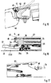
- the longitudinally movable Roof sections D2 and D3 different closing or opening and Take release positions I to V, which is shown in more detail in FIGS. 1 to 8.
- Fig. 1 is the sliding roof 1 with the first three movable roof sections D1, D2 and D3 shown in closed position I.
- first Roof section D1 when the adjoining roof sections D2 and Set up D3 at an angle.
- first roof section D1 or completely closed second and / or third roof section D2 and / or D3 to open or to incline.
- the two adjoining movable roof sections D2 and D3 are individually by themselves and independent of each other in a release and Locking position adjustable.
- the second roof section D 2 after a Longitudinal displacement in the direction of arrow A2 uncover its roof opening 4 with length L1.
- the third roof section D3 after a longitudinal displacement in the direction of the arrow A3 (Fig. 6) release its roof opening 6 with the length L2.
- the two movable roof sections D2 and D3 against the direction of travel F to the rear be moved so that there is a roof opening 7 with the length L of the length of the results in two roof sections D2 and D3.
- the first roof section D1 can only be adjusted at an angle, and this is preferably Roof section D1 only set up if one of the two roof sections D2 and D3 in is moved in any way. Control such that this inclined adjustment of the first roof section D1 when the roof sections D2 and / or D3 move is also conceivable.
- An inclined adjustment of the third roof section D3 is shown in more detail in FIG. 5. Possible is also that both roof sections D2 and D3 or either one of the two Roof sections D1 or D2 or D3 can be adjusted at an angle.
- the side guide rails 2 and 3 each have two U-shaped profiles P1 and P2 with receiving chambers 8 and 9 for displacement and adjustment or Actuators of the roof sections D2 and D3 on what is shown in Fig. 14 in more detail is.
- One chamber 8 is on the outside and can be used to hold the guiding and adjusting or Actuating means for the first and second roof sections D1 and D2 are used.
- the second chamber 9 inside can be used for receiving Guide and actuating or actuating means are used for the third roof section D3. It it is thus possible to use the guiding and adjusting or actuating means of the roof sections D1, D2 and D3 can be arranged either in chambers 8 or 9.
- the guide rails 2 and 3 are hidden below an outer roof contour K. arranged and the receiving chambers 8 and 9 are provided side by side. A connection of the guide rail 2 or 3 with the body structure of the vehicle takes place via the side rails 10 of the vehicle roof.
- the guide rails 2 and 3 each have the outer profile P1, which forms the chamber 8, an approximately horizontally aligned and for On the outside of the vehicle protruding web 11, at least above a web 12 of the side rail 10 rests. A connection with this takes place via screwing means 13, which is shown in more detail in Fig. 13.
- the actuating and actuating means for raising or lowering the movable Roof section D2 for opening and closing the roof opening 4 and 7 consist of in the guide rails 2 and 3 movable scenes 15 and 16 with guide slots 17, 17a and 18, in which roof-mounted link pins 19 and 20 are guided (Fig. 9 and 14). Furthermore, a backdrop 21 is provided for the first roof section D1 in FIG whose guide slot 22 engages a fixed link pin 23 and the Controls pivoting movement of the roof section D1.
- the control of the wind deflector slat or the first roof section D1 takes place in the Way that the backdrop (15) of the second roof section D2 against the Direction F moves with an empty path and the wind deflector lamella or Roof section D1 pivots before the roof section D2 in his Open position moved.
- a lifting movement which is shown in more detail in Fig. 2.
- sliding elements 25 and 26 longitudinally displaceable, which is connected to an actuating element 27 of the roof section D3 are (Figs. 10, 16 and 19).
- the sliding elements 25 and 26 have a raised Guide rail 28 or 28a and are encompassed by slide cams 29 and 29a, so that when the sliding elements 25 and 26 move along the Guide rail 28 an adjustment of the roof section D3 in vertical Lowering movement as well as a longitudinal movement is effected.
- a plurality of circular channels 30 are provided in the guide rails 2 and 3, in which actuation cables or the like. Adjustment means are arranged, which the backdrop 15 or 16, 21 and the sliding elements 25 and 26 drive to a closing or To achieve release position of the roof sections D1, D2 and D3.
- the third roof section D3 When the third roof section D3 is released, it moves vertically downward directed lifting movement of this roof section, which a subsequent, against the Direction F directional longitudinal movement follows.
- the third roof section D3 takes one Location below the fixed fourth roof section D4, the second roof section D2 remains in position flush with the fourth roof section D4.
- the second and third roof sections D2 and D3 take a position above and below the fixed fourth roof section D4, with the front end edges S2 to S4 of all three roof sections D2, D3 and D4 approximately in a vertical plane X-X lie on top of each other.
- the first roof section D1 forms the wind deflector slat and is opposite to the other roof sections run relatively narrow.
- the roof sections can each have different lengths but also the same lengths in such a way that a maximum opening through the roof sections D2 and D3 results.
- roof sections D1, D2, D3 and D4 can be made of a transparent transparent material, such as glass.
- the inner profile P2 of the guide rail 2 or 3 has profiled projections 35 in the manner of a groove 36 in which a sun blind 37 is guided laterally.
- Another profiled molding 38 serves to fix a roof cladding 39 (Fig. 12).
- the guide rail 2 or 3 is on the outer profile P1 provided with a towering leg 40 (Fig. 11) which is at least laterally the Side edges of the roof sections D1, D2, D3 and D4 extends, the others Legs 41 and 42 of the profiles P1 and P2 are below the roof sections D2, D3 and D4.
- the towering leg 40 has the outside lying profile P1 of the guide rail 2 or 3 at the free end of the Side edges S2, S3 and S4 of the roof sections D2, D3 and D4 respectively Chamber profile seal 44 on the roof in the area of a passing Holding element 45 for the link pin 19 can be pushed away. In front of and behind this The chamber profile gasket rests on the side edges, so that a Tightness is achieved.
- the one Sealing strip 46 consists of an elastic hollow chamber profile and the other opposite sealing strip 47 can consist of an elastic full strip.
- Below the hollow section is one with a transverse groove provided support profile 48 connected to the roof section D2, D3 and D4.
- a sealing strip 46 consisting of a hollow chamber profile is arranged, which corresponds to a sealing strip 51 on the front end edge S1 of the first Roof section D1 is arranged.
- This hollow chamber profile seals the front roof section in a closed position, being in the open position the front free end of the roof section D1 is immersed in a transverse rail.
- the rear fixed roof portion D4 is transverse in its attachment to the rear extending roof spar 10a shown.
- This fixed roof section D4 is via holding or Fastening means 50 on the one hand with the guide rail 2 or 3 in the profile P1 connected at the bottom and on the other hand there is a connection on the roof strut 10a intended.
- a substantial increase in the structural rigidity is achieved because the fixed roof section D4 is integrated directly into the structure.
Landscapes
- Engineering & Computer Science (AREA)
- Mechanical Engineering (AREA)
- Body Structure For Vehicles (AREA)
- Seal Device For Vehicle (AREA)
- Power-Operated Mechanisms For Wings (AREA)
Abstract
Description
- Fig. 1 bis Fig. 8
- die möglichen Öffnungs- und Schließstellungen der Dachabschnitte des mehrteiligen Schiebedaches,
- Fig. 9
- eine Seitenansicht auf den ersten und teilweise auf den zweiten Dachabschnitt mit einer Kulisse für den ersten und Kulissen für den zweiten Dachabschnitt,
- Fig. 10
- eine Seitenansicht auf den dritten Dachabschnitt mit Stell- und Gleitelementen,
- Fig. 11
- einen Schnitt durch eine Führungsschiene mit angedeuteter Kulisse für den zweiten Dachabschnitt und einen angedeuteten Gleitstein mit Stellelement für den dritten Dachabschnitt,
- Fig. 12
- einen Schnitt durch die Führungsschiene mit Befestigungsprofil für einen Dachhimmel und einer Führung für ein Sonnenrollo,
- Fig. 13
- einen Schnitt durch die Führungsschiene mit einer Schraubverbindung an einem seitlichen Dachholm,
- Fig. 14
- einen Schnitt durch die Führungsschiene mit einer Darstellung der Kulisse für den vorderen Dachabschnitt sowie Führungsverbindungen der Kulisse über einen Kulissenzapfen,
- Fig. 15
- einen Schnitt durch einen vorderen, quer verlaufenden Dachholm und durch den ersten Dachabschnitt mit stirnseitiger Dichtung,
- Fig. 16
- eine Seitenansicht auf die letzten drei übereinander angeordneten Dachabschnitte mit Dichtungen der vorderen Stirnkanten,
- Fig. 17
- eine Seitenansicht auf eine Stirnkantendichtung vom dritten zum vierten Dachabschnitt in einer schräggestellten Position des dritten Dachabschnitts,
- Fig. 18
- eine Seitenansicht gem. Fig. 17 bei geschlossener Position des dritten Dachabschnitts,
- Fig. 19
- die vergrößerte Darstellung X gem. Fig. 10 des dachseitigen Stellelements mit Gleitelementen und
- Fig. 20
- einen Schnitt durch einen heckseitigen, quer verlaufenden Dachholm mit Anbindung des festen hinteren Dachabschnitts.
Claims (21)
- Mehrteiliges Schiebedach (1) für ein Kraftfahrzeug mit einem ersten winkelbeweglichen Dachabschnitt (D1) und mindestens einem zweiten (D2) und dritten (D3) in Fahrzeuglängsrichtung längs bewegbaren Dachabschnitt zum positionierten Verschließen und Freigeben einer Dachöffnung (F) und einen an diese bewegbaren Dachabschnitte anschließenden vierten festen Dachabschnitt (D4), wobei die längs bewegbaren Dachabschnitte in Führungsschienen (2 und 3) mittels Stell- Verschiebe- und Betätigungselemente angesteuert verfahrbar sind, wobei der erste Dachabschnitt (D1) zu einem positionierten beweglichen zweiten oder dritten Dachabschnitts (D2 bzw. D3) schräg stellbar ist und die anschließenden Dachabschnitte (D2 oder D3) sowohl einzeln für sich und voneinander unabhängig als auch nacheinander über in den Führungsschienen (2 und 3) verschiebbare Kulissen (15 bzw. 16) und über die Stellelemente (27) in eine Freigabe- und Verschließposition verstellbar sind, derart, dass der zweite und der dritte Dachabschnitt (D2 bzw. D3) jeweils seine Dachöffnung (4 bzw. 6) und infolge beide Dachabschnitte (D2 und D3) zusammen die gesamte Dachöffnung (7) freigebend längs verschiebbar in den Führungsschienen (2 und 3) angeordnet sind und zumindest ein beweglicher Dachabschnitt (D2 oder D3) oder beide Dachabschnitte (D2 und D3) in der Verschließposition schräg stellbar ist bzw. sind.
- Schiebedach nach Anspruch 1, dadurch gekennzeichnet, dass bei einer Freigabebewegung des zweiten Dachabschnitts (D2) eine vertikal aufwärts gerichtete Hubbewegung mit einer anschließenden, entgegen der Fahrtrichtung (F) gerichteten Längsbewegung gekoppelt ist und der zweite Dachabschnitt (D2) eine Lage oberhalb des dritten Dachabschnitts (D3) oder vierten Dachabschnitts (D4) aufweist und dieser dritte Dachabschnitt (D3) bündig mit dem vierten festen Dachabschnitt (D4) angeordnet ist.
- Schiebedach nach Anspruch 1 oder 2, dadurch gekennzeichnet, dass bei einer Freigabebewegung des dritten Dachabschnitts (D3) eine vertikal abwärts gerichtete Hubbewegung mit einer anschließend entgegen der Fahrtrichtung (F) gerichteten Längsbewegung gekoppelt ist und der dritte Dachabschnitt (D3) unterhalb des festen vierten Dachabschnitts (D4) verschiebbar ist, wobei der zweite Dachabschnitt (D2) bündig mit dem vierten Dachabschnitt (D4) angeordnet ist.
- Schiebedach nach Anspruch 1, dadurch gekennzeichnet, dass der zweite und/oder dritte Dachabschnitt (D2 bzw. D3) jeweils in eine Schrägstellung mittels der Stell- Verschiebe- und Betätigungselemente einstellbar ist.
- Schiebedach nach einem der Ansprüche 1, 2 oder 3, dadurch gekennzeichnet, dass der zweite und der dritte Dachabschnitt (D2 bzw. D3) gemeinsam oberhalb und unterhalb des festen vierten Dachabschnitts (D4) verschiebbar sind, wobei die vorn liegenden Stirnkanten (S2 bis S4) aller drei Dachabschnitte (D2, D3 und D4) annähernd in einer vertikalen Ebene (X-X) übereinander liegen.
- Schiebedach nach einem der Ansprüche 1 bis 5, dadurch gekennzeichnet, dass zwischen Seitenholmen (10) des Fahrzeugdachs der Aufbaustruktur die Führungsschienen (2 und 3) mindestens jeweils zwei profilierte Aufnahmekammern (8 bzw. 9) für die Verschiebe- und Stell- bzw. Betätigungselemente ( Bauelemente 15, 16, 21 und 25 bis 29) der Dachabschnitte (D1, D2 bzw. D3) aufweisen und unterhalb einer äußeren Dachkontur (K) verdeckt angeordnet und jeweils mit den Seitenholmen (10) der Aufbaustruktur verbunden sind, wobei die Aufnahmekammern (8 und 9) der Führungsschienen (2 bzw. 3) zur fixierten seitlichen Lagerung der Dachabschnitte (D1 bis D4) etwa in einer horizontalen Ebene (Y-Y) nebeneinander liegend angeordnet sind.
- Schiebedach nach einem der vorhergehenden Ansprüche, dadurch gekennzeichnet, dass das aus den vier Abschnitten (D1, D2, D3 und D4) bestehende Fahrzeugdach mit den seitlichen Führungsschienen (2 bzw. 3) sowie den Verschiebe- und Stell- bzw. Betätigungselementen (Bauelemente 15, 16, 21 und 25 bis 29) ein in eine Dachöffnung als vorgefertigte Baueinheit einsetzbares Funktionsmodul besteht, welches mit vorderen, hinteren und seitlichen Dachholmen (49, 10 bzw. 10a) der Fahrzeugaufbaustruktur verbindbar ist.
- Schiebedach nach einem der vorhergehenden Ansprüche, dadurch gekennzeichnet, dass der erste Dachabschnitt (D1) gegenüber den weiteren Dachabschnitten (D2, D3 bzw. D4) in der Länge schmäler ausgeführt ist und eine Windabweiserlamelle bildet.
- Schiebedach nach einem der vorhergehenden Ansprüche, dadurch gekennzeichnet, dass die Dachabschnitte (D1 bis D4) aus einem transparenten bzw. aus einem undurchsichtigen Werkstoff bestehen.
- Schiebedach nach einem der Ansprüche 6 bis 9, dadurch gekennzeichnet, dass die Führungsschienen (2 und 3) aus zwei im Querschnitt annähernd U-förmigen Profilen (P1 bzw. P2) bestehen, wobei das außen liegende Profil (P1) die erste Kammer (8) zur Aufnahme der Führungs- und Stell- bzw. Betätigungsmitteln für den ersten und den zweiten Dachabschnitt (D1 bzw. D2) sowie zur Abstützung des vierten festen Dachabschnitts (D4) über Halte- und Befestigungsmittel (50) aufweist.
- Schiebedach nach einem der Ansprüche 6 bis 10, dadurch gekennzeichnet, dass das innen liegende Profil (P2) der Führungsschiene (2 bzw. 3) die zweite Kammer (9) zur Aufnahme von Führungs- und Stell- bzw. Betätigungsmitteln für den dritten Dachabschnitt (D3) aufweist.
- Schiebedach nach einem der Ansprüche 6 bis 11, dadurch gekennzeichnet, dass die Kammern (8 und 9) wahlweise zur Aufnahme der Führungs- und Stell- bzw. Betätigungsmittel für den ersten und den zweiten Dachabschnitt (D1 bzw. D2) und wahlweise zur Aufnahme von Führungs- und Stell- bzw. Betätigungsmitteln für den dritten Dachabschnitt (D3) aufweist.
- Schiebedach nach einem der vorhergehenden Ansprüche, dadurch gekennzeichnet, dass die Führungsschiene (2 bzw. 3) eine Führung (Anformung 35) für ein Sonnenrollo (37) und eine Aufnahme (Anformung 38) zur Befestigung einer Dachverkleidung (39) aufweist.
- Schiebedach nach einem der vorhergehenden Ansprüche, dadurch gekennzeichnet, dass am außen liegenden Profil (P1) der Führungsschiene (2 bzw. 3) ein etwa horizontal ausgerichteter und zur Fahrzeugaußenseite hin wegragender Steg (11) vorgesehen ist, der zumindest mit einem Seitenholm (10) der Fahrzeugaufbaustruktur über Schraubmittel (13) verbindbar ist.
- Schiebedach nach einem der vorhergehenden Ansprüche, dadurch gekennzeichnet, dass das außen liegende Profil (P1) der Führungsschiene (2 bzw. 3) die Dachabschnitte (D2, D3 und D4) mit einem hochragenden Schenkel (40) teilweise seitlich übergreift, wobei das innen liegende Profil (P2) im Wesentlichen unterhalb der Dachabschnitte (D2, D3 bzw. D4) angeordnet ist.
- Schiebedach nach einem der vorhergehenden Ansprüche, dadurch gekennzeichnet, dass im außen liegenden Profil (P1) der Führungsschiene (2 bzw. 3), die Kulissen (21 und 15 bzw. 16) für den ersten Dachabschnitt (D1) bzw. für den zweiten Dachabschnitt (D2) sowie in kreisförmigen Führungen (Kanal 30) Betätigungsseile längs verschiebbar geführt sind und in Führungsschlitzen (22 und 17 bzw. 17a) der Kulisse (21 und 15 bzw. 16) mit dem ersten und zweiten Dachabschnitt (D1 bzw. D2) verbundene Kulissenzapfen (23, 19 bzw. 20) eingreifen.
- Schiebedach nach einem der vorhergehenden Ansprüche, dadurch gekennzeichnet, dass im innen liegenden Profil (P2) der Führungsschiene (2 bzw. 3) zwei miteinander verbundene Gleitelemente (25 und 26) längs verschiebbar geführt sind, die mit Führungen (Schiene 28 bzw. 28a) eines am dritten Dachabschnitt (D3) verbundenen Stellelements (Gleitnocken 29 bzw. 29a) in Eingriff stehen.
- Schiebedach nach einem der Ansprüche 15 bis 17, dadurch gekennzeichnet, dass der hoch ragende Schenkel (40) des außen liegenden Profils (P1) der Führungsschiene (2 bzw. 3) am freien Ende eine den Stirnkanten (S2, S3 bzw. S4) der Dachabschnitte (D2, D3 bzw. D4) zugerichtete Kammerprofildichtung (44) aufweist, die im Bereich eines passierenden dachfesten Halteelements (45) zumindest für den Kulissenzapfen (19) wegdrückbar ist.
- Schiebedach nach einem der vorhergehenden Ansprüche, dadurch gekennzeichnet, dass zwischen den Dachabschnitten (D1, D2, D3 und D4) im Bereich der Stirnkanten (S2, S3 bzw. S4) jeweils gegenüberstehende Dichtleisten (46 und 47) angeordnet sind, wobei die eine Dichtleiste (46) aus einem elastischen Profil und die weitere gegenüberstehende Dichtleiste (47) aus einer elastischen Vollleiste besteht und unterhalb des Hohlkammerprofils jeweils ein mit einer quer verlaufenden Rinne versehenes Trägerprofil (48) mit den Dachabschnitten (D2, D3 bzw. D4) verbunden ist.
- Schiebedach nach einem der vorhergehenden Ansprüche, dadurch gekennzeichnet, dass zumindest an einem vorderen quer verlaufenden Dachholm (49) der Aufbaustruktur des Fahrzeugs eine aus dem Profil bestehende Dichtleiste (46) angeordnet ist, die korrespondierend mit einer Dichtleiste (51) an der vorderen Stirnkante (S1) des ersten Dachabschnitts (D1) angeordnet ist.
- Schiebedach nach einem der vorhergehenden Ansprüche, dadurch gekennzeichnet, dass die Dachabschnitte (D1, D2, D3 bzw. D4) jeweils eine unterschiedliche Länge aufweisen, derart, dass der vordere, als Windabweiserlamelle ausgebildete erste Dachabschnitt (D1) die geringste Länge gegenüber den weiteren Dachabschnitten (D2, D3 und D4) aufweist und der zweite Dachabschnitt (D2) eine größere Länge als der dritte Dachabschnitt (D3) besitzt und der feste Dachabschnitt (D4) eine größere Länge als jeder Dachabschnitt (D1, D2 bzw. D3) aufweist.
Applications Claiming Priority (2)
| Application Number | Priority Date | Filing Date | Title |
|---|---|---|---|
| DE19941984A DE19941984C1 (de) | 1999-09-03 | 1999-09-03 | Mehrteiliges Schiebedach für ein Kraftfahrzeug |
| DE19941984 | 1999-09-03 |
Publications (3)
| Publication Number | Publication Date |
|---|---|
| EP1080963A2 true EP1080963A2 (de) | 2001-03-07 |
| EP1080963A3 EP1080963A3 (de) | 2002-07-24 |
| EP1080963B1 EP1080963B1 (de) | 2004-06-09 |
Family
ID=7920648
Family Applications (1)
| Application Number | Title | Priority Date | Filing Date |
|---|---|---|---|
| EP00116931A Expired - Lifetime EP1080963B1 (de) | 1999-09-03 | 2000-08-05 | Mehrteiliges Schiebedach für ein Kraftfahrzeug |
Country Status (8)
| Country | Link |
|---|---|
| US (1) | US6443520B1 (de) |
| EP (1) | EP1080963B1 (de) |
| JP (1) | JP2001080362A (de) |
| KR (1) | KR100701118B1 (de) |
| CN (1) | CN1188297C (de) |
| AT (1) | ATE268701T1 (de) |
| DE (1) | DE19941984C1 (de) |
| ES (1) | ES2218036T3 (de) |
Cited By (3)
| Publication number | Priority date | Publication date | Assignee | Title |
|---|---|---|---|---|
| EP1338455A1 (de) * | 2002-02-20 | 2003-08-27 | Webasto Vehicle Systems International GmbH | Windabweiseranordnung für ein öffnungsfähiges Fahrzeugdach |
| DE202010003554U1 (de) | 2009-08-12 | 2010-07-15 | Emrich, Jörg T. | Hardtop Falt- und Schiebedach |
| DE102009037374A1 (de) | 2009-08-12 | 2011-02-17 | Emrich, Jörg T. | Hardtop Falt- und Schiebedach |
Families Citing this family (38)
| Publication number | Priority date | Publication date | Assignee | Title |
|---|---|---|---|---|
| DE29820613U1 (de) * | 1998-11-18 | 2000-03-30 | Meritor Automotive Gmbh | Schiebedach für Fahrzeuge |
| DE10062736B4 (de) * | 2000-12-15 | 2007-09-06 | Webasto Ag | Öffnungsfähiges Fahrzeugdach |
| DE60134119D1 (de) * | 2001-04-03 | 2008-07-03 | Inalfa Roof Sys Group Bv | Konstruktion eines öffnungsfähigen Fahrzeugsdaches |
| DE10133436A1 (de) * | 2001-07-10 | 2003-01-30 | Arvinmeritor Gmbh | Modul, insbesondere Schiebedachmodul für ein Fahrzeug |
| US7374226B2 (en) * | 2002-04-12 | 2008-05-20 | Edscha Cabrio-Dachsysteme Gmbh | Folding top for a cabriolet vehicle |
| DE10235901A1 (de) * | 2002-08-06 | 2004-02-19 | Dr.Ing.H.C. F. Porsche Ag | Verfahren zum Bewegen eines mehrteiligen Schiebedaches für ein Kraftfahrzeug |
| EP1393946B1 (de) * | 2002-08-30 | 2007-12-12 | Webasto AG | Fahrzeugdach mit zwei Dachöffnungen |
| DE10309145C5 (de) * | 2003-02-28 | 2012-08-09 | Webasto Ag | Fahrzeugdach |
| DE10327540B4 (de) * | 2003-06-18 | 2008-09-04 | Webasto Ag | Öffnungsfähiges Fahrzeugdach |
| DE10327559B4 (de) * | 2003-06-18 | 2008-08-07 | Webasto Ag | Öffnungsfähiges Fahrzeugdach |
| DE102004009049B4 (de) * | 2004-02-23 | 2005-11-17 | Cts Fahrzeug-Dachsysteme Gmbh | Fahrzeugdach mit mindestens zwei verstellbaren Dachteilen |
| DE102004048140A1 (de) * | 2004-10-02 | 2006-04-13 | Daimlerchrysler Ag | Kraftfahrzeug |
| DE102005047505B4 (de) * | 2005-10-04 | 2008-09-25 | Magna Car Top Systems Gmbh | Fahrzeugdach mit mindestens zwei öffnungsfähigen Dachteilen |
| DE102006000848B3 (de) * | 2006-01-05 | 2007-08-02 | Magna Car Top Systems Gmbh | Dach für ein Kraftfahrzeug |
| DE102006042262A1 (de) * | 2006-09-08 | 2008-03-27 | Dr.Ing.H.C. F. Porsche Ag | Cabriolet |
| US7850231B2 (en) * | 2007-08-10 | 2010-12-14 | Yachiyo Industry Co., Ltd. | Sunroof apparatus for vehicle |
| US8814258B2 (en) * | 2008-08-15 | 2014-08-26 | Ford Global Technologies, Llc | Panoramic vehicle roof module assemblies |
| US7922242B2 (en) * | 2008-08-15 | 2011-04-12 | Ford Global Technologies, Llc | Panoramic vehicle roof module assemblies |
| JP5351485B2 (ja) * | 2008-10-16 | 2013-11-27 | 八千代工業株式会社 | サンルーフ装置 |
| JP5309922B2 (ja) * | 2008-11-20 | 2013-10-09 | アイシン精機株式会社 | 車両用シェード装置 |
| CN101712272B (zh) * | 2009-11-24 | 2011-11-23 | 浙江胜华波电器股份有限公司 | 一种车用全景可折叠式天窗遮阳板 |
| DE102010012942A1 (de) * | 2010-03-26 | 2011-09-29 | Webasto Ag | Fahrzeugdach mit Polycarbonatdeckel |
| DE102010048257B4 (de) * | 2010-10-12 | 2012-08-16 | Webasto Ag | Fahrzeugdach |
| CN102490578A (zh) * | 2011-12-14 | 2012-06-13 | 黄孝庆 | 一种三节自动收缩式硬顶车顶棚 |
| US9162556B2 (en) | 2012-04-04 | 2015-10-20 | Ford Global Technologies, Llc | Panoramic roof module for a vehicle |
| US9248725B2 (en) | 2012-04-04 | 2016-02-02 | Ford Global Technologies, Llc | Panoramic roof module for a vehicle |
| DE102012104280B4 (de) * | 2012-05-16 | 2015-04-02 | Webasto SE | Fahrzeugdach mit zwei Deckelelementen |
| DE102013108294B4 (de) * | 2013-08-01 | 2016-02-18 | Winfried Reif | Dachbaugruppe und Kraftfahrzeug |
| US9296282B2 (en) * | 2014-04-28 | 2016-03-29 | Inalfa Roof Systems Group B.V. | Open roof construction for a vehicle |
| DE102016100772A1 (de) * | 2016-01-19 | 2017-07-20 | Webasto SE | Anordnung für ein Fahrzeugdach, System und Verfahren zum Herstellen einer Anordnung für ein Fahrzeugdach |
| DE202017107486U1 (de) * | 2017-12-08 | 2019-03-12 | Inalfa Roof Systems Group B.V. | Offendachkonstruktion für ein Fahrzeug, und Fahrzeug mit einer solchen Offendachkonstruktion |
| DE102018123185B4 (de) * | 2018-09-20 | 2020-07-16 | Webasto SE | Fahrzeugdach mit Führungskanälen für Rollobahn |
| KR102621543B1 (ko) * | 2018-12-11 | 2024-01-04 | 현대자동차주식회사 | 양방향 오픈 선루프 구조 |
| US10800236B2 (en) | 2019-02-15 | 2020-10-13 | Ford Global Technologies, Llc | Soft top convertible wind deflector |
| US10857862B2 (en) | 2019-02-15 | 2020-12-08 | AISIN Technical Center of America, Inc. | Dual panel sunroof systems and apparatus for use with vehicles |
| JP7153165B2 (ja) * | 2020-04-02 | 2022-10-13 | 八千代工業株式会社 | シェードガイド構造 |
| DE102020214245A1 (de) * | 2020-11-12 | 2022-05-12 | Bos Gmbh & Co. Kg | Fahrzeugdachsystem für ein Kraftfahrzeug |
| DE102020214247A1 (de) * | 2020-11-12 | 2022-05-12 | Bos Gmbh & Co. Kg | Fahrzeugdachsystem |
Citations (3)
| Publication number | Priority date | Publication date | Assignee | Title |
|---|---|---|---|---|
| DE4227400A1 (de) | 1992-08-19 | 1994-02-24 | Webasto Karosseriesysteme | Schiebedach |
| EP0648629A1 (de) | 1993-10-15 | 1995-04-19 | Dr.Ing.h.c. F. Porsche Aktiengesellschaft | Aufbau für Personenwagen |
| WO1996001192A1 (en) | 1994-07-05 | 1996-01-18 | Asc Incorporated | Automobile sunroof assembly and control system |
Family Cites Families (10)
| Publication number | Priority date | Publication date | Assignee | Title |
|---|---|---|---|---|
| GB573355A (en) * | 1943-12-10 | 1945-11-16 | Edgar Walter Neale | Improvements relating to slidable roofs for motor vehicle saloon bodies |
| JPH0620672Y2 (ja) * | 1987-08-31 | 1994-06-01 | ダイキョー・ベバスト株式会社 | サンルーフ装置 |
| FR2636892B1 (fr) * | 1988-09-26 | 1990-12-07 | Heuliez Henri France Design | Dispositif d'ouverture de toit a au moins deux volets orientables |
| US5197779A (en) * | 1989-06-27 | 1993-03-30 | Mazda Motor Corporation | Power sliding sunroof |
| DE4313555C1 (de) * | 1993-04-26 | 1994-05-26 | Webasto Karosseriesysteme | Dachkonstruktion eines Fahrzeuges |
| DE19549200A1 (de) * | 1995-12-30 | 1997-07-03 | Webasto Karosseriesysteme | Windleitelement für ein Fahrzeugdach |
| KR19980054269A (ko) * | 1996-12-27 | 1998-09-25 | 김영귀 | 차량의 루프덮개 다단접철방법 |
| US6129413A (en) * | 1997-11-13 | 2000-10-10 | Asc Incorporated | Powered dual panel sunroof |
| DE29820613U1 (de) * | 1998-11-18 | 2000-03-30 | Meritor Automotive Gmbh | Schiebedach für Fahrzeuge |
| DE19924792C1 (de) * | 1999-05-29 | 2000-08-10 | Webasto Vehicle Sys Int Gmbh | Fahrzeugdach mit wenigstens zwei ausstellbaren und verschiebbaren starren Deckelelementen |
-
1999
- 1999-09-03 DE DE19941984A patent/DE19941984C1/de not_active Expired - Fee Related
-
2000
- 2000-08-05 ES ES00116931T patent/ES2218036T3/es not_active Expired - Lifetime
- 2000-08-05 AT AT00116931T patent/ATE268701T1/de active
- 2000-08-05 EP EP00116931A patent/EP1080963B1/de not_active Expired - Lifetime
- 2000-08-31 JP JP2000263280A patent/JP2001080362A/ja active Pending
- 2000-09-01 KR KR1020000051461A patent/KR100701118B1/ko not_active IP Right Cessation
- 2000-09-04 CN CNB001268376A patent/CN1188297C/zh not_active Expired - Fee Related
- 2000-09-05 US US09/654,904 patent/US6443520B1/en not_active Expired - Lifetime
Patent Citations (3)
| Publication number | Priority date | Publication date | Assignee | Title |
|---|---|---|---|---|
| DE4227400A1 (de) | 1992-08-19 | 1994-02-24 | Webasto Karosseriesysteme | Schiebedach |
| EP0648629A1 (de) | 1993-10-15 | 1995-04-19 | Dr.Ing.h.c. F. Porsche Aktiengesellschaft | Aufbau für Personenwagen |
| WO1996001192A1 (en) | 1994-07-05 | 1996-01-18 | Asc Incorporated | Automobile sunroof assembly and control system |
Cited By (3)
| Publication number | Priority date | Publication date | Assignee | Title |
|---|---|---|---|---|
| EP1338455A1 (de) * | 2002-02-20 | 2003-08-27 | Webasto Vehicle Systems International GmbH | Windabweiseranordnung für ein öffnungsfähiges Fahrzeugdach |
| DE202010003554U1 (de) | 2009-08-12 | 2010-07-15 | Emrich, Jörg T. | Hardtop Falt- und Schiebedach |
| DE102009037374A1 (de) | 2009-08-12 | 2011-02-17 | Emrich, Jörg T. | Hardtop Falt- und Schiebedach |
Also Published As
| Publication number | Publication date |
|---|---|
| CN1287064A (zh) | 2001-03-14 |
| US6443520B1 (en) | 2002-09-03 |
| JP2001080362A (ja) | 2001-03-27 |
| KR20010030212A (ko) | 2001-04-16 |
| EP1080963B1 (de) | 2004-06-09 |
| DE19941984C1 (de) | 2000-10-19 |
| EP1080963A3 (de) | 2002-07-24 |
| CN1188297C (zh) | 2005-02-09 |
| ATE268701T1 (de) | 2004-06-15 |
| ES2218036T3 (es) | 2004-11-16 |
| KR100701118B1 (ko) | 2007-03-29 |
Similar Documents
| Publication | Publication Date | Title |
|---|---|---|
| DE19941984C1 (de) | Mehrteiliges Schiebedach für ein Kraftfahrzeug | |
| EP0591644B1 (de) | Fahrzeugdach mit einer Folge von Lamellen | |
| DE10033887C1 (de) | Fahrzeugdach mit wenigstens einem oberhalb des festen Fahrzeugdachs verschiebbaren Deckel | |
| DE69925359T3 (de) | Schiebedach für fahrzeuge | |
| DE4227400C2 (de) | Schiebedach | |
| DE69933248T2 (de) | Öffnungsfähige Dachkonstruktion für ein Fahrzeug, und ein Fahrzeug mit einer derartigen öffnungsfähigen Dachkonstruktion | |
| DE19914427C2 (de) | Kraftfahrzeugdach | |
| EP1586475A2 (de) | Schiebedachsystem | |
| EP0584496A1 (de) | Fahrzeugdach | |
| EP0734894A2 (de) | Aufbau für Personenwagen | |
| DE2759029C2 (de) | ||
| DE3733227A1 (de) | Schiebedachvorrichtung fuer ein fahrzeug | |
| EP0494356B1 (de) | Faltdach für Fahrzeuge | |
| DE4238945C1 (de) | Hebeschiebedach für Fahrzeuge | |
| EP1393945B1 (de) | Fahrzeugdach mit einem die Dachhaut verschliessenden nach hinten verschiebbaren Deckel | |
| DE4438104C1 (de) | Schiebehimmelanordnung für ein Fahrzeugdach | |
| DE4111931C1 (en) | Slide canopy for car sun roof - in two parts, one telescopically insertable, at least partly, into second part | |
| DE10158174B4 (de) | Schiebehebedach für Fahrzeuge | |
| WO2021130001A1 (de) | Fahrzeugdach, umfassend ein dachöffnungssystem mit zwei kinematikeinheiten | |
| DE10237543A1 (de) | Fahrzeugdach | |
| DE4142265C1 (en) | Car sun roof with rigid lid(s) - has roof railing with side screens along its length in section protruding beyond roof skin in sun roof open position | |
| DE4041908C1 (en) | Sliding roof for motor vehicle - has CAM surfaces on cross-member to guide leading canopy over rear canopy | |
| DE19613761C1 (de) | Öffnungsfähiges Fahrzeugdach | |
| DE4301635C1 (de) | Rahmenanordnung für ein Fahrzeugdach | |
| DE19543244C2 (de) | Fahrzeugdach |
Legal Events
| Date | Code | Title | Description |
|---|---|---|---|
| PUAI | Public reference made under article 153(3) epc to a published international application that has entered the european phase |
Free format text: ORIGINAL CODE: 0009012 |
|
| AK | Designated contracting states |
Kind code of ref document: A2 Designated state(s): AT BE CH CY DE DK ES FI FR GB GR IE IT LI LU MC NL PT SE |
|
| AX | Request for extension of the european patent |
Free format text: AL;LT;LV;MK;RO;SI |
|
| PUAL | Search report despatched |
Free format text: ORIGINAL CODE: 0009013 |
|
| AK | Designated contracting states |
Kind code of ref document: A3 Designated state(s): AT BE CH CY DE DK ES FI FR GB GR IE IT LI LU MC NL PT SE |
|
| AX | Request for extension of the european patent |
Free format text: AL;LT;LV;MK;RO;SI |
|
| RIC1 | Information provided on ipc code assigned before grant |
Free format text: 7B 60J 7/047 A, 7B 60J 7/043 B, 7B 60J 7/22 B |
|
| 17P | Request for examination filed |
Effective date: 20030124 |
|
| AKX | Designation fees paid |
Designated state(s): AT BE CH CY DE DK ES FI FR GB GR IE IT LI LU MC NL PT SE |
|
| 17Q | First examination report despatched |
Effective date: 20030325 |
|
| RBV | Designated contracting states (corrected) |
Designated state(s): AT BE CH CY DK ES FI FR GB GR IE IT LI LU MC NL PT SE |
|
| REG | Reference to a national code |
Ref country code: DE Ref legal event code: 8566 |
|
| GRAP | Despatch of communication of intention to grant a patent |
Free format text: ORIGINAL CODE: EPIDOSNIGR1 |
|
| GRAS | Grant fee paid |
Free format text: ORIGINAL CODE: EPIDOSNIGR3 |
|
| GRAA | (expected) grant |
Free format text: ORIGINAL CODE: 0009210 |
|
| AK | Designated contracting states |
Kind code of ref document: B1 Designated state(s): AT BE CH CY DK ES FI FR GB GR IE IT LI LU MC NL PT SE |
|
| PG25 | Lapsed in a contracting state [announced via postgrant information from national office to epo] |
Ref country code: FI Free format text: LAPSE BECAUSE OF FAILURE TO SUBMIT A TRANSLATION OF THE DESCRIPTION OR TO PAY THE FEE WITHIN THE PRESCRIBED TIME-LIMIT Effective date: 20040609 Ref country code: NL Free format text: LAPSE BECAUSE OF FAILURE TO SUBMIT A TRANSLATION OF THE DESCRIPTION OR TO PAY THE FEE WITHIN THE PRESCRIBED TIME-LIMIT Effective date: 20040609 Ref country code: CY Free format text: LAPSE BECAUSE OF FAILURE TO SUBMIT A TRANSLATION OF THE DESCRIPTION OR TO PAY THE FEE WITHIN THE PRESCRIBED TIME-LIMIT Effective date: 20040609 Ref country code: IE Free format text: LAPSE BECAUSE OF FAILURE TO SUBMIT A TRANSLATION OF THE DESCRIPTION OR TO PAY THE FEE WITHIN THE PRESCRIBED TIME-LIMIT Effective date: 20040609 |
|
| REG | Reference to a national code |
Ref country code: GB Ref legal event code: FG4D Free format text: NOT ENGLISH |
|
| REG | Reference to a national code |
Ref country code: CH Ref legal event code: EP |
|
| GBT | Gb: translation of ep patent filed (gb section 77(6)(a)/1977) |
Effective date: 20040705 |
|
| REG | Reference to a national code |
Ref country code: IE Ref legal event code: FG4D Free format text: GERMAN |
|
| PG25 | Lapsed in a contracting state [announced via postgrant information from national office to epo] |
Ref country code: LU Free format text: LAPSE BECAUSE OF NON-PAYMENT OF DUE FEES Effective date: 20040805 |
|
| PG25 | Lapsed in a contracting state [announced via postgrant information from national office to epo] |
Ref country code: MC Free format text: LAPSE BECAUSE OF NON-PAYMENT OF DUE FEES Effective date: 20040831 Ref country code: CH Free format text: LAPSE BECAUSE OF NON-PAYMENT OF DUE FEES Effective date: 20040831 Ref country code: BE Free format text: LAPSE BECAUSE OF NON-PAYMENT OF DUE FEES Effective date: 20040831 Ref country code: LI Free format text: LAPSE BECAUSE OF NON-PAYMENT OF DUE FEES Effective date: 20040831 |
|
| REG | Reference to a national code |
Ref country code: SE Ref legal event code: TRGR |
|
| PG25 | Lapsed in a contracting state [announced via postgrant information from national office to epo] |
Ref country code: GR Free format text: LAPSE BECAUSE OF FAILURE TO SUBMIT A TRANSLATION OF THE DESCRIPTION OR TO PAY THE FEE WITHIN THE PRESCRIBED TIME-LIMIT Effective date: 20040909 Ref country code: DK Free format text: LAPSE BECAUSE OF FAILURE TO SUBMIT A TRANSLATION OF THE DESCRIPTION OR TO PAY THE FEE WITHIN THE PRESCRIBED TIME-LIMIT Effective date: 20040909 |
|
| REG | Reference to a national code |
Ref country code: ES Ref legal event code: FG2A Ref document number: 2218036 Country of ref document: ES Kind code of ref document: T3 |
|
| NLV1 | Nl: lapsed or annulled due to failure to fulfill the requirements of art. 29p and 29m of the patents act | ||
| ET | Fr: translation filed | ||
| REG | Reference to a national code |
Ref country code: IE Ref legal event code: FD4D |
|
| BERE | Be: lapsed |
Owner name: DR.ING. H.C.F. PORSCHE A.G. Effective date: 20040831 |
|
| PLBE | No opposition filed within time limit |
Free format text: ORIGINAL CODE: 0009261 |
|
| REG | Reference to a national code |
Ref country code: CH Ref legal event code: PL |
|
| STAA | Information on the status of an ep patent application or granted ep patent |
Free format text: STATUS: NO OPPOSITION FILED WITHIN TIME LIMIT |
|
| 26N | No opposition filed |
Effective date: 20050310 |
|
| BERE | Be: lapsed |
Owner name: *HCF PORSCHE A.G. Effective date: 20040831 |
|
| PG25 | Lapsed in a contracting state [announced via postgrant information from national office to epo] |
Ref country code: PT Free format text: LAPSE BECAUSE OF NON-PAYMENT OF DUE FEES Effective date: 20041109 |
|
| PGFP | Annual fee paid to national office [announced via postgrant information from national office to epo] |
Ref country code: ES Payment date: 20080828 Year of fee payment: 9 |
|
| PGFP | Annual fee paid to national office [announced via postgrant information from national office to epo] |
Ref country code: SE Payment date: 20080815 Year of fee payment: 9 |
|
| REG | Reference to a national code |
Ref country code: FR Ref legal event code: TP |
|
| REG | Reference to a national code |
Ref country code: FR Ref legal event code: CD |
|
| REG | Reference to a national code |
Ref country code: ES Ref legal event code: FD2A Effective date: 20090806 |
|
| REG | Reference to a national code |
Ref country code: FR Ref legal event code: TP |
|
| REG | Reference to a national code |
Ref country code: GB Ref legal event code: 732E Free format text: REGISTERED BETWEEN 20110310 AND 20110316 |
|
| REG | Reference to a national code |
Ref country code: GB Ref legal event code: 732E Free format text: REGISTERED BETWEEN 20110331 AND 20110406 |
|
| PG25 | Lapsed in a contracting state [announced via postgrant information from national office to epo] |
Ref country code: SE Free format text: LAPSE BECAUSE OF NON-PAYMENT OF DUE FEES Effective date: 20090806 |
|
| PG25 | Lapsed in a contracting state [announced via postgrant information from national office to epo] |
Ref country code: ES Free format text: LAPSE BECAUSE OF NON-PAYMENT OF DUE FEES Effective date: 20090806 |
|
| PGFP | Annual fee paid to national office [announced via postgrant information from national office to epo] |
Ref country code: GB Payment date: 20110819 Year of fee payment: 12 Ref country code: FR Payment date: 20110901 Year of fee payment: 12 Ref country code: AT Payment date: 20110812 Year of fee payment: 12 |
|
| PGFP | Annual fee paid to national office [announced via postgrant information from national office to epo] |
Ref country code: IT Payment date: 20110825 Year of fee payment: 12 |
|
| REG | Reference to a national code |
Ref country code: AT Ref legal event code: MM01 Ref document number: 268701 Country of ref document: AT Kind code of ref document: T Effective date: 20120805 |
|
| GBPC | Gb: european patent ceased through non-payment of renewal fee |
Effective date: 20120805 |
|
| REG | Reference to a national code |
Ref country code: FR Ref legal event code: ST Effective date: 20130430 |
|
| PG25 | Lapsed in a contracting state [announced via postgrant information from national office to epo] |
Ref country code: IT Free format text: LAPSE BECAUSE OF NON-PAYMENT OF DUE FEES Effective date: 20120805 |
|
| PG25 | Lapsed in a contracting state [announced via postgrant information from national office to epo] |
Ref country code: AT Free format text: LAPSE BECAUSE OF NON-PAYMENT OF DUE FEES Effective date: 20120805 |
|
| PG25 | Lapsed in a contracting state [announced via postgrant information from national office to epo] |
Ref country code: GB Free format text: LAPSE BECAUSE OF NON-PAYMENT OF DUE FEES Effective date: 20120805 |
|
| PG25 | Lapsed in a contracting state [announced via postgrant information from national office to epo] |
Ref country code: FR Free format text: LAPSE BECAUSE OF NON-PAYMENT OF DUE FEES Effective date: 20120831 |