EP1079033A2 - Système de traitement d'eaux usées - Google Patents
Système de traitement d'eaux usées Download PDFInfo
- Publication number
- EP1079033A2 EP1079033A2 EP00307130A EP00307130A EP1079033A2 EP 1079033 A2 EP1079033 A2 EP 1079033A2 EP 00307130 A EP00307130 A EP 00307130A EP 00307130 A EP00307130 A EP 00307130A EP 1079033 A2 EP1079033 A2 EP 1079033A2
- Authority
- EP
- European Patent Office
- Prior art keywords
- waste water
- water treatment
- louver
- channel
- energized
- Prior art date
- Legal status (The legal status is an assumption and is not a legal conclusion. Google has not performed a legal analysis and makes no representation as to the accuracy of the status listed.)
- Granted
Links
- 238000004065 wastewater treatment Methods 0.000 title claims abstract description 80
- 239000002351 wastewater Substances 0.000 claims abstract description 84
- 239000010865 sewage Substances 0.000 claims abstract description 45
- XLYOFNOQVPJJNP-UHFFFAOYSA-N water Substances O XLYOFNOQVPJJNP-UHFFFAOYSA-N 0.000 claims description 23
- 230000007246 mechanism Effects 0.000 claims description 20
- 239000012858 resilient material Substances 0.000 claims description 3
- 238000011068 loading method Methods 0.000 abstract description 3
- 239000002244 precipitate Substances 0.000 description 19
- 239000007788 liquid Substances 0.000 description 13
- 238000000926 separation method Methods 0.000 description 11
- 239000007787 solid Substances 0.000 description 11
- 239000002361 compost Substances 0.000 description 10
- 239000006228 supernatant Substances 0.000 description 10
- 239000010802 sludge Substances 0.000 description 9
- 238000005192 partition Methods 0.000 description 8
- 241000894006 Bacteria Species 0.000 description 7
- 238000000151 deposition Methods 0.000 description 6
- 239000011368 organic material Substances 0.000 description 5
- 239000000969 carrier Substances 0.000 description 4
- 230000005465 channeling Effects 0.000 description 4
- 230000008021 deposition Effects 0.000 description 4
- 238000000034 method Methods 0.000 description 4
- 230000008569 process Effects 0.000 description 4
- 230000015556 catabolic process Effects 0.000 description 3
- 238000006731 degradation reaction Methods 0.000 description 3
- 238000007599 discharging Methods 0.000 description 3
- 239000012530 fluid Substances 0.000 description 3
- 239000000463 material Substances 0.000 description 3
- 230000001376 precipitating effect Effects 0.000 description 3
- 239000000701 coagulant Substances 0.000 description 2
- 238000000354 decomposition reaction Methods 0.000 description 2
- 238000000746 purification Methods 0.000 description 2
- 238000009825 accumulation Methods 0.000 description 1
- 238000005273 aeration Methods 0.000 description 1
- 238000010276 construction Methods 0.000 description 1
- 238000010586 diagram Methods 0.000 description 1
- 239000003337 fertilizer Substances 0.000 description 1
- 238000001914 filtration Methods 0.000 description 1
- 230000008595 infiltration Effects 0.000 description 1
- 238000001764 infiltration Methods 0.000 description 1
- 230000007257 malfunction Effects 0.000 description 1
- 230000013011 mating Effects 0.000 description 1
- 235000013372 meat Nutrition 0.000 description 1
- 239000000203 mixture Substances 0.000 description 1
- 238000012986 modification Methods 0.000 description 1
- 230000004048 modification Effects 0.000 description 1
- 230000002093 peripheral effect Effects 0.000 description 1
- 230000001681 protective effect Effects 0.000 description 1
- 230000009467 reduction Effects 0.000 description 1
- 229920002379 silicone rubber Polymers 0.000 description 1
- 239000011343 solid material Substances 0.000 description 1
- 238000003756 stirring Methods 0.000 description 1
- 230000007704 transition Effects 0.000 description 1
- 239000002699 waste material Substances 0.000 description 1
Images


Classifications
-
- E—FIXED CONSTRUCTIONS
- E03—WATER SUPPLY; SEWERAGE
- E03C—DOMESTIC PLUMBING INSTALLATIONS FOR FRESH WATER OR WASTE WATER; SINKS
- E03C1/00—Domestic plumbing installations for fresh water or waste water; Sinks
- E03C1/12—Plumbing installations for waste water; Basins or fountains connected thereto; Sinks
- E03C1/26—Object-catching inserts or similar devices for waste pipes or outlets
- E03C1/266—Arrangement of disintegrating apparatus in waste pipes or outlets; Disintegrating apparatus specially adapted for installation in waste pipes or outlets
- E03C1/2665—Disintegrating apparatus specially adapted for installation in waste pipes or outlets
-
- B—PERFORMING OPERATIONS; TRANSPORTING
- B09—DISPOSAL OF SOLID WASTE; RECLAMATION OF CONTAMINATED SOIL
- B09B—DISPOSAL OF SOLID WASTE NOT OTHERWISE PROVIDED FOR
- B09B5/00—Operations not covered by a single other subclass or by a single other group in this subclass
-
- E—FIXED CONSTRUCTIONS
- E03—WATER SUPPLY; SEWERAGE
- E03C—DOMESTIC PLUMBING INSTALLATIONS FOR FRESH WATER OR WASTE WATER; SINKS
- E03C1/00—Domestic plumbing installations for fresh water or waste water; Sinks
- E03C1/12—Plumbing installations for waste water; Basins or fountains connected thereto; Sinks
- E03C1/26—Object-catching inserts or similar devices for waste pipes or outlets
- E03C1/266—Arrangement of disintegrating apparatus in waste pipes or outlets; Disintegrating apparatus specially adapted for installation in waste pipes or outlets
-
- Y—GENERAL TAGGING OF NEW TECHNOLOGICAL DEVELOPMENTS; GENERAL TAGGING OF CROSS-SECTIONAL TECHNOLOGIES SPANNING OVER SEVERAL SECTIONS OF THE IPC; TECHNICAL SUBJECTS COVERED BY FORMER USPC CROSS-REFERENCE ART COLLECTIONS [XRACs] AND DIGESTS
- Y02—TECHNOLOGIES OR APPLICATIONS FOR MITIGATION OR ADAPTATION AGAINST CLIMATE CHANGE
- Y02W—CLIMATE CHANGE MITIGATION TECHNOLOGIES RELATED TO WASTEWATER TREATMENT OR WASTE MANAGEMENT
- Y02W30/00—Technologies for solid waste management
- Y02W30/50—Reuse, recycling or recovery technologies
Definitions
- the invention relates to a system for treating waste water from a crusher such as a disposer containing crushed garbage, allowing efficient waste water drainage to a sewage system.
- a typical waste water treating system known as all-volume type (or purification tank type), is disclosed in Japanese Patent Publication No. 9-155385 (C02F 3/30), which has a waste water treatment apparatus for processing waste water containing crushed garbage from a disposer as well as waste water directly from a sink not containing crushed garbage.
- Another type of waste water processing system includes a motor driven switcher for channeling the waste water to a waste water treatment apparatus if the water comes from a disposer but otherwise channeling it directly to a sewage system.
- the all-volume type waste water treatment apparatus has a drawback in that it must have a volume as large as a purification tank, and therefore requires a large construction work to bury the tank in the ground, which is difficult to apply to existing houses.
- waste water treatment systems are designed to run a waste water treatment apparatus only when a disposer is optionally turned on by a user.
- waste water is passed to the waste water treatment apparatus by a water channel switcher which establishes connection between the disposer and the waste water treatment apparatus only when the disposer is in operation.
- This type of waste water treatment systems advantageously have much smaller dimensions.
- the switcher would remain connected thereto even after the power failure, thereby causing ordinary waste water to flow into the waste water treatment apparatus, in excess of the treatment ability of the waste water treatment apparatus.
- the invention aims to provide a small sized waste water treatment system which is equipped with a water channel switcher and capable of successfully continuing its operation and preventing such overflow as mentioned above even under a power failure.
- a waste water treatment system of the invention is characterized by a supplementary return mechanism added to an electric switching means for controlling said water channel switcher which is adapted to switch a water channel leading to a sewage line to a water channel leading to a line connected to a waste water treatment apparatus when said garbage crusher is in operation, said supplementary return mechanism adapted to force said water channel switcher to restore said water channel leading to said sewage line if said electric switching means is de-energized.
- the switcher will be automatically returned to the home position at which the sink drain is channeled to the sewage system to prevent an excessive flow of water into the waste water treatment apparatus, hence preventing degradation of performance of the waste water treatment apparatus.
- the water channel switcher of the invention comprises:
- This return mechanism utilizes the restoring force of a spring in returning the water channel switcher to the home position, thereby directing the flow of waste water to the sewage line when the motor is de-energized.
- the water channel switcher may be provided at the upper end of the casing with a joint pipe mounted on the inlet of the switcher for directing, via the open end thereof, incoming waste water to the waste water treatment line formed in the bottom of the casing.
- waste water containing crushed garbage is directed naturally to the waste water treatment line, preventing the crushed garbage from hitting the inner walls of the casing and from depositing inside the casing.
- the louver may be provided with side walls formed along the inner surface of the casing.
- Such side walls of the louver will prevent the waste water from directly hitting the inner surface of the casing, thereby preventing deposition of garbage on the inner surface of the casing.
- the right and left sections of the casing preferably have mating flanges so that they can be coupled together to form water tight seal for the casing.
- the louver is preferably pivotally mounted in the casing by a pivot provided at the lower end of the louver such that the pivot is supported by bearings provided inside the casing and covered with a spoiler covering the bearings.
- the lower end of the louver may be extended downwardly over the pivot and the bearings to prevent crushed garbage from entering the bearings and depositing therein.
- a separator formed of a resilient material may be provided between the two outlets, extending over the louver and between the side walls of the louver and the casing.
- the soft separator will be useful to prevent damaging the louver with crushed garbage pieces which deposit on the side walls and the upper end of the louver and get caught between the louver walls and the separator.
- the water channel switcher may be provided with:
- the waste water treatment system With the rotatable bent pipe and the means for forcing the bent pipe, the waste water treatment system will be protected against an excessive flow of water even in a case of a power failure and maintain its rated treatment ability.
- the water channel switcher may comprise:
- this arrangement also prevents excessive flow of waste water into the waste water treatment apparatus and possible degradation of the apparatus resulting from the excessive flow during power failure.
- a waste water treatment system including a disposer 2 connected to a sink 11 of a kitchen sink unit 1, a water channel switcher 3 for switching water channels between a waste water line 21 of the disposer 2 and a first line (referred to as waste water treatment line) 31 which is in turn connected to a waste water treatment apparatus 4 and a second line (referred to as sewage line) 32 leading to a sewage system.
- waste water treatment line a first line
- waste water treatment apparatus 4 referred to as sewage line
- the waste water containing crushed garbage generated by the disposer is normally lead to the waste water treatment apparatus 4 by the water channel switcher 3 for separating the garbage and water, and the water thus recovered by the apparatus 4 is discharged to the sewage line 32.
- ordinary waste water not containing garbage materials will be channeled directly to the sewage system through the sewage line 32.
- the waste water treatment apparatus 4 shown in Fig. 2, consists of: a flow regulation tank 41 which receives waste water containing crushed garbage from the disposer via the water channel switcher 3; a solid-liquid separator 42 for separating from the waste water precipitated solid materials; a treatment tank 43 for treating the supernatant water sent from the flow regulation tank 41; a precipitate separation tank 44 for precipitating the sludge which was formed in the treatment tank 43; a coagulant injector 45 for injecting coagulant into the supernatant in the precipitate separation tank 44; a compost tank 46 for separating solid components which precipitate in the solid-liquid separator 42; and air lift pumps 47, 48, and 49 for transporting fluid to and from the tanks.
- the air lift pumps are a type of tubes adapted to transport materials floating in the fluid within the tube by the lift of air bubbles injected into the tube.
- each of the air lift pumps 47, 48, and 49 of Fig. 2 is schematically shown by a simple thick arrow, it actually consists of an air lift pipe and a blower pump.
- the blower pumps may be replaced by a common blower pump which has a multi-directional valve for switching different pipes.
- the air lift pump 47 for lifting precipitate in the flow regulation tank 41 to the solid-liquid separator 42, and the air lift pump 48 for lifting the supernatant in the flow regulation tank 41 to the treatment tank 43.
- the solid-liquid separator 42 can be a filtering mesh, for example.
- the treatment tank 43 may be a tank for treating organic materials by microaerophilic bacteria in a well known process such as for example an activated sludge process, a contact aeration process, and a carrier fluidized bed process.
- the treatment tank 43 is ventilated by a blower pump 431 and an air diffuser 432.
- the treatment tank 43 shown in Fig. 2 is a carrier fluidized bed type treatment tank in which carriers 433 carrying thereon inhabiting microaerophilic bacteria are circulated.
- the water channel switcher 3 is switched so that waste water is channeled to the flow regulation tank 41 through the line 31 to thereby treating crushed garbage in the waste water.
- a mixture of solids and water in the flow regulation tank 41 is pumped up to the solid-liquid separator 42 by an air lift pump 47, where water is separated from solids.
- the water separated by the solid-liquid separator 42 is returned to the flow regulation tank 41, and the solids are deposited in the compost tank 46.
- the supernatant in the flow regulation tank 41 is transported to the treatment tank 43 by an air lift pump 48.
- Precipitating sludge in the precipitate separation tank 44 is removed therefrom back to the flow regulation tank 41 by the air lift pump 49.
- the sludge transferred to the flow regulation tank 41 is again mixed with fresh crushed garbage from the disposer 2 and sent to the solid-liquid separator 42 by the air lift pump 47 for further separation of water and solids.
- Solid components collected in the compost tank 46 is decomposed by the bacteria accommodated on, and incubated by, wooden chips in the compost tank 46, and turned to a compost heap, which is later collected as a fertilizer.
- a user confirms on a control panel (not shown) adjacent the sink unit 1 that the disposer 2 can be operated, throw garbage into the disposer 2, and then turn on the switch on the control panel.
- the throwing of the switch will cause the water channel switcher 3 to establish a channel between the disposer and the waste water treatment apparatus 4 before the disposer 2 is started. Subsequently the disposer 2 will be started, crushing the garbage, which will be transported into the flow regulation tank 41 as described above.
- Solid components in the sludge will precipitate in the flow regulation tank 41 in about half an hour.
- the supernatant in the flow regulation tank 41 is pumped to the treatment tank 43 by the air lift pump 48.
- Supernatant overflowing the treatment tank 43 enters the precipitate separation tank 44.
- the sludge accumulating in the precipitate separation tank 44 will be returned to the flow regulation tank 41 by an air lift pump 49.
- solid components are separated from liquid components and transferred to the compost tank 46, while the liquid components are returned to the flow regulation tank 41.
- the compost tank 46 contains bacteria carriers in the form of wooden chips, as described previously, to promote decomposition of organic materials in the solids.
- the compost tank 46 is provided with a stirrer to stir the content at a regular interval.
- the treatment tank 43 organic materials conveyed by the supernatant from the flow regulation tank 41 are decomposed by the bacteria. Overflowing supernatant in the treatment tank 43 is passed to the precipitate separation tank 44.
- the treatment tank 43 accommodates porous carriers 433 which helps maintain a desirable biological environment for the bacteria.
- the porous carriers 433 are put into circulation in the tank 43 by air bubbles generated by an air diffuser 432 which spout the air supplied by the blower pump 431.
- the organic materials thus decomposed into sludge in the treatment tank 43 are sent to the precipitate separation tank 44 and precipitate therein, which precipitate is then returned to the flow regulation tank 41 by the air lift pump 49.
- the precipitate is later recovered in the solid-liquid separator 42 together with solids garbage and sent to the compost tank 46 for further decomposition.
- the precipitate will be changed to compost.
- the water channel switcher 3 has a louver 34 which is driven by a geared motor 33.
- the louver 34 is pivotally mounted between a right and a left casing 35a and 35b, respectively, forming together the casing of the water channel switcher 3, with a separator 36 interposing between the louver 34 and the casing.
- Formed in the upper end of the water channel switcher 3 are an waste water inlet connected to the waste water line 21 extending from the disposer 2 and a joint pipe 37 connected to the waste water inlet.
- the water channel switcher 3 has a sewage outlet 351 formed in one corner of the bottom of the water channel switcher 3 for discharging waste water into the sewage line 32 and another outlet 352 (referred to as waste water treatment outlet) formed on the other corner of the bottom for discharging garbage containing water to the waste water treatment line 31 connected to the waste water treatment apparatus 4.
- the louver 34 is pivotally mounted between the outlets 351 and 352.
- the louver 34 has louver walls 341 and 342 on the opposite sides of a partition wall 340.
- An inclined spoiler 343 extends from the middle of the partition wall 340 towards the outlet 351.
- louver drive pins 344 and 345 are also formed at the opposite lower sections of the louver walls 341 and 342.
- a pivot 346 is formed on the partition wall 340 and on the same side of the partition wall 340 as the spoiler 343.
- Fig. 4 illustrates an arrangement of the geared motor 33 as viewed from the front (Fig. 4A) and from the rear (Figs. 4B and 4C) of the motor 33, showing the mechanism of the geared motor 33.
- the geared motor 33 has a reduction gear and an electromagnetic clutch housed in a motor casing, and a motor shaft 331 extending through the rear end of the casing.
- a rod 332 is mounted on the extended end of the shaft 331. Hooked at the remote end of the rod from the shaft 331 is a spring 333. The spring is secured at the opposite end thereof to a point on the rear of the motor casing.
- the geared motor 33 is positioned initially at its home position as shown in Figs. 4A and 4B when it is not energized. As it is switched on, the rod 332 mounted on the shaft 331 is rotated in the counterclockwise direction, stretching the spring 333, until the rod 332 turns on the electromagnetic clutch to hold the rod 332 at the position as shown in Fig. 4C.
- the geared motor 33 is secured on the outer surface of the left casing 35a by means of appropriate fastening means such as screws, as shown in Fig. 3, such that the louver drive pin 344 penetrates the louver drive pin bores 353 formed on the left casing 35a and fits in the rod 332.
- louver drive pin bores 353 and 354 Formed in the right and left casings 35a and 35b are louver drive pin bores 353 and 354, grooves 355 for receiving therein the separator 36, and sleeve bearings 356 for receiving therein pivot 346 of the louver 34.
- the separator 36 has an inverted U-shape. It is formed of a resilient, chemically and thermally stable material such as silicon rubber.
- the separator 36 is fitted in the grooves 355 of the right and the left casings 35a and 35b, respectively, by first placing the separator on both sides 341 and 342 of the louver 34 from above and next securing together outer flanges 357 of the right and the left casings 35a and 35b, respectively, by screws.
- the pivot 346 of the louver 34 is fitted in the sleeve bearings 356 formed on the right and the left casings 35a and 35b, respectively.
- the joint pipe 37 is secured on the inlet formed in the upper corner of the right and the left casings 35a and 35b, respectively.
- the joint pipe 37 has a bent section which is inclined downwardly into the casings.
- outer flanges 357 of the right and the left casings 35a and 35b, respectively, are sealably coupled to prevent leakage of water from the casing.
- the joint pipe 37 is connected to the waste water line 21 to receive from the disposer 2 waste water containing crushed garbage when the disposer is in operation, but otherwise receives ordinary waste water from the sink.
- the water channel switcher assembly 3 works as follows.
- Fig. 5A shows the condition of the water channel switcher 3 when the disposer 2 is not in operation.
- the spoiler 343 prevents the waste water from reaching the spaces between the pivot 346 and the sleeve bearings 356, thereby preventing accumulation of garbage therein, and also preventing leak of the waste water to the garbage treatment outlet 352.
- Fig. 5B shows a condition of the water channel switcher 3 when the disposer 2 is in operation so that the water channel switcher 3 receives crushed garbage through the joint pipe 37.
- the geared motor 33 is energized to bring the louver drive pins 344 and 345 to the position shown in Fig. 5B, so that the partition wall 340 of the louver 34 is inclined past the mouth of the joint pipe 37 as shown. Waste water containing crushed garbage flowing into the water channel switcher 3 through the joint pipe 37 will fall into the outlet 352 through the upper section of the louver 34, leaving little or no garbage on the inner walls of the casing. As the flow of the water containing garbage is reduced, it tends to drop and flow on the partition wall 340 of the louver 34. In this case too, the right and the left walls 341 and 342 help prevent deposition of crushed garbage on the casing.
- Deposition of crushed garbage and leak of waste water into the bearings 356 and the sewage line 351 may be further prevented by an overlapping section 347 formed at the lower end of the louver 34 to extend over the sleeve bearings 356.
- louver 34 Should power failure occur while the louver 34 is in operation at the position shown in Fig. 5B, or halfway from the home position shown in Fig. 5A to the position shown in Fig. 5B, the louver 34 would be instantly returned to the home position as described previously, thereby securing a sewage channel for the ordinary waste water from the kitchen sink. Accordingly, in such cases as discussed above, an excessive flow of waste water into the waste water treatment apparatus 4 will not occur and no degradation of treatment power of the waste water treatment apparatus take place.
- louver 34 will not be able to return from the working condition shown in Fig. 5B to the home position shown in Fig. 5A if the spring 333 is broken by accident for example.
- Fig. 6A shows an instance where the spring 333 is broken while the louver 34 remains at the working position, receiving an excessive amount of waste water from the disposer 2, and directing the water to the waste water treatment outlet 352. Therefore, it is likely that the waste water treatment apparatus will eventually loose its ability by the excessive charging of the waste water.
- the louver drive pin 345 shown in Fig. 6A may be extended through the pin bore 354 and through the right casing 35b so that the extended louver drive pin may be manually operated to bring the louver 34 back to the home position shown in Fig. 6B.
- the extended louver drive pin 345 may have a larger rotational radius about the pivot 356 than the drive pin 344 for ease of the manual operation of the louver drive pin 345.
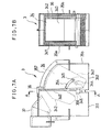
- Fig. 7B shows the cross section of the louver taken along line A-A of Fig. 7A.
- the separator 36 may be formed of a resilient material to abut on the upper end and on the opposite sides of the louver 34 as shown in Fig. 7B, so that, if crushed garbage deposits on the upper end and the side walls, it could be scraped off by the separator 36. If not scraped off and trapped between them, the garbage will not damage the louver 34.
- Figs. 8 through 12 show details of another type of water channel switcher 3 of the invention.
- a water channel switcher 3 is provided with a rotatable elbow pipe 38 connected, via a seal member 22, to the waste water line 21 extending from the disposer 2.
- a pivot 381 which is coaxial with the waste water line 21 and connected with the motor shaft 331 of the geared motor 33 mounted on a stay 334.
- the elbow pipe 38 has a convexed open end seating on two concaved mouths, that is, the sewage outlet 311 and the waste water treatment outlet 321, both having the same radius of curvature as the open end of the elbow 38, as shown in Fig. 9.
- the two outlets 311 and 321 are led to the waste water treatment line 31 connected to the waste water treatment apparatus 4 and to the sewage line 32 connected to the sewage line.
- the geared motor 33 may be the same as the one used in the foregoing example, but the shaft of the motor is directly coupled with the pivot 381 of the elbow pipe 38.
- the motor shaft 331 is coupled at one peripheral point thereof with a spring as shown in Fig. 10. The opposite end of the spring is secured to a point on the motor casing.
- Figs. 10A and 10B the geared motor 33 operates in substantially the same manner as described previously in conjunction with Figs. 4A-C. That is, when the geared motor 33 is energized, the motor shaft 331 is rotated in the counterclockwise direction from the home position shown in Fig. 10A, stretching the spring 333, until it reaches the position shown in Fig. 10B to turn on a built-in electromagnetic clutch, which holds the shaft 331 at that position.
- the geared motor 33 When a power failure takes place, the geared motor 33 is returned to the home position shown in Fig. 10A, thereby bringing the elbow pipe 38 to its home position shown in Fig. 11 to channel the waste water from the kitchen sink to the sewage system.
- Fig. 13 shows a further example of water channel switcher 3, in which the channel switcher 3 is provided with a branching section 39 having a pivotal switching board 34a for branching the flow of water.
- the switching board 34a has a pivot 346a which is always urged in one direction by a torsion spring 333a mounted on the pivot 346a so as to shut off the water channel to the line 31 connected to the waste water treatment apparatus 4.
- the pivot 346a is connected with a rotary solenoid 33a which, when energized, rotates the switching board 34a against the torsional force of the spring 333a to shut off the water channel to the sewage line 32 connected to the sewage system.
- the rotary solenoid 33a When the disposer 2 is in operation, the rotary solenoid 33a is turned on to rotate the switching board 34a to shut off the channel to the sewage pipe 32.
- the rotary solenoid 33a When the disposer 2 is not in operation, the rotary solenoid 33a is also de-energized (including cases of power failure), so that the torsional force of the spring 333a will shut off the water passage to the waste water treatment apparatus 4.
- the disposer may be appropriately substituted for by another type of crusher such as a meat grinder.
- the waste water treatment apparatus is not limited to the one shown in Fig. 2: it can be any such compact apparatus.
- the precipitate in the flow regulation tank 41 may be alternatively air lifted to the solid-liquid separator 42, and the fluid components discharged into the treatment tank 43.
- An additional tank may be optionally provided, between the kitchen sink and the flow regulation tank 41, for storing waste water from the kitchen sink and transferring only concentrated waste water from the tank to the flow regulation tank 41 and discharge the overflowing supernatant to the sewage line 32.
Landscapes
- Engineering & Computer Science (AREA)
- Environmental & Geological Engineering (AREA)
- Water Supply & Treatment (AREA)
- Life Sciences & Earth Sciences (AREA)
- Hydrology & Water Resources (AREA)
- Public Health (AREA)
- Health & Medical Sciences (AREA)
- Crushing And Pulverization Processes (AREA)
- Processing Of Solid Wastes (AREA)
- Sink And Installation For Waste Water (AREA)
- Excavating Of Shafts Or Tunnels (AREA)
- Removal Of Specific Substances (AREA)
- Separation Using Semi-Permeable Membranes (AREA)
Applications Claiming Priority (2)
| Application Number | Priority Date | Filing Date | Title |
|---|---|---|---|
| JP23586899 | 1999-08-23 | ||
| JP11235868A JP2001058174A (ja) | 1999-08-23 | 1999-08-23 | 生ごみ処理システム |
Publications (3)
| Publication Number | Publication Date |
|---|---|
| EP1079033A2 true EP1079033A2 (fr) | 2001-02-28 |
| EP1079033A3 EP1079033A3 (fr) | 2002-11-20 |
| EP1079033B1 EP1079033B1 (fr) | 2007-04-11 |
Family
ID=16992448
Family Applications (1)
| Application Number | Title | Priority Date | Filing Date |
|---|---|---|---|
| EP00307130A Expired - Lifetime EP1079033B1 (fr) | 1999-08-23 | 2000-08-21 | Système de traitement d'eaux usées |
Country Status (7)
| Country | Link |
|---|---|
| EP (1) | EP1079033B1 (fr) |
| JP (1) | JP2001058174A (fr) |
| KR (1) | KR100359178B1 (fr) |
| CN (1) | CN1285317A (fr) |
| AT (1) | ATE359405T1 (fr) |
| DE (1) | DE60034280T2 (fr) |
| TW (1) | TW527323B (fr) |
Cited By (5)
| Publication number | Priority date | Publication date | Assignee | Title |
|---|---|---|---|---|
| ITUD20090164A1 (it) * | 2009-09-17 | 2011-03-18 | Architetto Chiavegato Adriano Ditta Individuale | Apparecchiatura e procedimento per il trattamento di rifiuti |
| FR2965737A1 (fr) * | 2010-10-06 | 2012-04-13 | Christophe Zyta | Installation de broyage et de recyclage de dechets organiques |
| CN108744707A (zh) * | 2018-06-21 | 2018-11-06 | 温州市聚达信息科技有限公司 | 一种节能污水循环过滤机 |
| CN109276219A (zh) * | 2018-09-14 | 2019-01-29 | 许昌涉步餐饮管理有限公司 | 一种厨房用具清洗装置 |
| CN111576563A (zh) * | 2020-05-28 | 2020-08-25 | 嘉兴学院 | 一种厨余垃圾处理装置 |
Families Citing this family (7)
| Publication number | Priority date | Publication date | Assignee | Title |
|---|---|---|---|---|
| JP2003097744A (ja) * | 2001-09-21 | 2003-04-03 | Sanyo Electric Co Ltd | 空気流路切替装置 |
| CN101658742B (zh) * | 2009-05-27 | 2011-06-29 | 北京嘉博文生物科技有限公司 | 餐厨垃圾受料机 |
| CA2872937A1 (fr) * | 2012-05-09 | 2013-11-14 | Solucycle Inc. | Dispositif et procede pour broyer et recuperer des dechets domestiques organiques |
| CN103510592B (zh) * | 2013-10-24 | 2015-04-22 | 泰州市厨房宝电器有限公司 | 一种垃圾处理过滤装置 |
| DE102014012242B4 (de) * | 2014-08-19 | 2021-03-04 | Dennis Rohde | Vorrichtung zur Notfallentwässerung |
| CN105289069A (zh) * | 2015-10-16 | 2016-02-03 | 重庆光煦科技有限公司 | 一种用于小区的集中化污水处理系统 |
| CN106113552B (zh) * | 2016-08-18 | 2018-12-28 | 深圳市格瑞汉兰科技有限公司 | 一种垃圾处理设备及垃圾处理方法 |
Citations (4)
| Publication number | Priority date | Publication date | Assignee | Title |
|---|---|---|---|---|
| JPH01199687A (ja) * | 1988-02-03 | 1989-08-11 | Hitachi Ltd | 厨芥処理装置および厨芥処理方法 |
| DE9111155U1 (de) * | 1991-09-09 | 1991-11-14 | Chen, Charles, Tao-Yuan City | Wiederaufbereitungsvorrichtung für die Küche |
| US5127587A (en) * | 1991-05-14 | 1992-07-07 | Johnson Harold R | Kitchen composter |
| US5971303A (en) * | 1998-03-23 | 1999-10-26 | Pugh-Gottlieb; Margaret | Waste router recycling system |
Family Cites Families (1)
| Publication number | Priority date | Publication date | Assignee | Title |
|---|---|---|---|---|
| US4917311A (en) * | 1988-09-27 | 1990-04-17 | Mitsubishi Denki Kabushiki Kaisha | Garbage disposer |
-
1999
- 1999-08-23 JP JP11235868A patent/JP2001058174A/ja active Pending
-
2000
- 2000-07-21 KR KR1020000041999A patent/KR100359178B1/ko not_active IP Right Cessation
- 2000-08-03 CN CN00120975A patent/CN1285317A/zh active Pending
- 2000-08-16 TW TW089116504A patent/TW527323B/zh not_active IP Right Cessation
- 2000-08-21 EP EP00307130A patent/EP1079033B1/fr not_active Expired - Lifetime
- 2000-08-21 AT AT00307130T patent/ATE359405T1/de not_active IP Right Cessation
- 2000-08-21 DE DE60034280T patent/DE60034280T2/de not_active Expired - Fee Related
Patent Citations (4)
| Publication number | Priority date | Publication date | Assignee | Title |
|---|---|---|---|---|
| JPH01199687A (ja) * | 1988-02-03 | 1989-08-11 | Hitachi Ltd | 厨芥処理装置および厨芥処理方法 |
| US5127587A (en) * | 1991-05-14 | 1992-07-07 | Johnson Harold R | Kitchen composter |
| DE9111155U1 (de) * | 1991-09-09 | 1991-11-14 | Chen, Charles, Tao-Yuan City | Wiederaufbereitungsvorrichtung für die Küche |
| US5971303A (en) * | 1998-03-23 | 1999-10-26 | Pugh-Gottlieb; Margaret | Waste router recycling system |
Non-Patent Citations (1)
| Title |
|---|
| PATENT ABSTRACTS OF JAPAN vol. 013, no. 501 (C-652), 10 November 1989 (1989-11-10) -& JP 01 199687 A (HITACHI LTD;OTHERS: 01), 11 August 1989 (1989-08-11) * |
Cited By (6)
| Publication number | Priority date | Publication date | Assignee | Title |
|---|---|---|---|---|
| ITUD20090164A1 (it) * | 2009-09-17 | 2011-03-18 | Architetto Chiavegato Adriano Ditta Individuale | Apparecchiatura e procedimento per il trattamento di rifiuti |
| EP2299010A1 (fr) * | 2009-09-17 | 2011-03-23 | Adriano Chiavegato | Dispositif et procédé pour traitement de déchets |
| FR2965737A1 (fr) * | 2010-10-06 | 2012-04-13 | Christophe Zyta | Installation de broyage et de recyclage de dechets organiques |
| CN108744707A (zh) * | 2018-06-21 | 2018-11-06 | 温州市聚达信息科技有限公司 | 一种节能污水循环过滤机 |
| CN109276219A (zh) * | 2018-09-14 | 2019-01-29 | 许昌涉步餐饮管理有限公司 | 一种厨房用具清洗装置 |
| CN111576563A (zh) * | 2020-05-28 | 2020-08-25 | 嘉兴学院 | 一种厨余垃圾处理装置 |
Also Published As
| Publication number | Publication date |
|---|---|
| JP2001058174A (ja) | 2001-03-06 |
| CN1285317A (zh) | 2001-02-28 |
| KR20010039739A (ko) | 2001-05-15 |
| EP1079033A3 (fr) | 2002-11-20 |
| EP1079033B1 (fr) | 2007-04-11 |
| TW527323B (en) | 2003-04-11 |
| DE60034280T2 (de) | 2007-12-20 |
| DE60034280D1 (de) | 2007-05-24 |
| KR100359178B1 (ko) | 2002-10-31 |
| ATE359405T1 (de) | 2007-05-15 |
Similar Documents
| Publication | Publication Date | Title |
|---|---|---|
| EP1079033B1 (fr) | Système de traitement d'eaux usées | |
| US20070199140A1 (en) | Device For Manufacturing Organic Compost From Excremet | |
| JPS591859B2 (ja) | 排水ます清掃装置 | |
| EP1081100A1 (fr) | Dispositif pour le traitement d'eaux usées | |
| CN2765832Y (zh) | 建筑工地车辆一体化冲洗装置 | |
| JP2003175373A (ja) | 厨芥処理システム | |
| CN210737726U (zh) | 一种移动交通工具的污物抽吸处理装置 | |
| JP3885917B2 (ja) | 厨芥処理システム | |
| CN1140677C (zh) | 排水处理系统 | |
| JP7485353B2 (ja) | 流体移送装置の移送方法および流体移送装置 | |
| KR200312537Y1 (ko) | 음식물 쓰레기 처리장치 | |
| WO2003057603A1 (fr) | Procede de manutention de dechets domestiques | |
| KR101152814B1 (ko) | 호기소화탈기탑 | |
| KR200285087Y1 (ko) | 공동주택 음식물 쓰레기 분리처리시스템 | |
| JP2000334433A (ja) | 厨芥処理システムおよび処理方法 | |
| JPH1157519A (ja) | 生ゴミ処理機およびそれを用いた生ゴミ粉砕発酵処理装置 | |
| JP2002143814A (ja) | 生ゴミ処理装置 | |
| JP2002186951A (ja) | 生ごみ処理システム | |
| JP3473377B2 (ja) | 生ごみ処理装置の制御構造 | |
| JPH0444536A (ja) | 厨芥処理装置 | |
| JP2001104815A (ja) | 生ごみ処理システム | |
| JP2001115518A (ja) | 厨芥処理システム | |
| JP4468735B2 (ja) | 砂分離洗浄装置 | |
| WO1995011201A1 (fr) | Installation de traitement des eaux usees et procede utilise dans cette installation | |
| JPH1133525A (ja) | 生ゴミ粉砕発酵処理装置 |
Legal Events
| Date | Code | Title | Description |
|---|---|---|---|
| PUAI | Public reference made under article 153(3) epc to a published international application that has entered the european phase |
Free format text: ORIGINAL CODE: 0009012 |
|
| AK | Designated contracting states |
Kind code of ref document: A2 Designated state(s): AT BE CH CY DE DK ES FI FR GB GR IE IT LI LU MC NL PT SE |
|
| AX | Request for extension of the european patent |
Free format text: AL;LT;LV;MK;RO;SI |
|
| PUAL | Search report despatched |
Free format text: ORIGINAL CODE: 0009013 |
|
| AK | Designated contracting states |
Kind code of ref document: A3 Designated state(s): AT BE CH CY DE DK ES FI FR GB GR IE IT LI LU MC NL PT SE |
|
| AX | Request for extension of the european patent |
Free format text: AL;LT;LV;MK;RO;SI |
|
| 17P | Request for examination filed |
Effective date: 20021231 |
|
| AKX | Designation fees paid |
Designated state(s): AT BE CH CY DE DK ES FI FR GB GR IE IT LI LU MC NL PT SE |
|
| GRAP | Despatch of communication of intention to grant a patent |
Free format text: ORIGINAL CODE: EPIDOSNIGR1 |
|
| RIC1 | Information provided on ipc code assigned before grant |
Ipc: B02C 18/00 20060101ALI20061204BHEP Ipc: E03C 1/266 20060101AFI20061204BHEP |
|
| GRAS | Grant fee paid |
Free format text: ORIGINAL CODE: EPIDOSNIGR3 |
|
| GRAA | (expected) grant |
Free format text: ORIGINAL CODE: 0009210 |
|
| AK | Designated contracting states |
Kind code of ref document: B1 Designated state(s): AT BE CH CY DE DK ES FI FR GB GR IE IT LI LU MC NL PT SE |
|
| PG25 | Lapsed in a contracting state [announced via postgrant information from national office to epo] |
Ref country code: FI Free format text: LAPSE BECAUSE OF FAILURE TO SUBMIT A TRANSLATION OF THE DESCRIPTION OR TO PAY THE FEE WITHIN THE PRESCRIBED TIME-LIMIT Effective date: 20070411 Ref country code: LI Free format text: LAPSE BECAUSE OF FAILURE TO SUBMIT A TRANSLATION OF THE DESCRIPTION OR TO PAY THE FEE WITHIN THE PRESCRIBED TIME-LIMIT Effective date: 20070411 Ref country code: CH Free format text: LAPSE BECAUSE OF FAILURE TO SUBMIT A TRANSLATION OF THE DESCRIPTION OR TO PAY THE FEE WITHIN THE PRESCRIBED TIME-LIMIT Effective date: 20070411 |
|
| REG | Reference to a national code |
Ref country code: GB Ref legal event code: FG4D |
|
| REG | Reference to a national code |
Ref country code: CH Ref legal event code: EP |
|
| REG | Reference to a national code |
Ref country code: IE Ref legal event code: FG4D |
|
| REF | Corresponds to: |
Ref document number: 60034280 Country of ref document: DE Date of ref document: 20070524 Kind code of ref document: P |
|
| PG25 | Lapsed in a contracting state [announced via postgrant information from national office to epo] |
Ref country code: SE Free format text: LAPSE BECAUSE OF FAILURE TO SUBMIT A TRANSLATION OF THE DESCRIPTION OR TO PAY THE FEE WITHIN THE PRESCRIBED TIME-LIMIT Effective date: 20070711 |
|
| PG25 | Lapsed in a contracting state [announced via postgrant information from national office to epo] |
Ref country code: ES Free format text: LAPSE BECAUSE OF FAILURE TO SUBMIT A TRANSLATION OF THE DESCRIPTION OR TO PAY THE FEE WITHIN THE PRESCRIBED TIME-LIMIT Effective date: 20070722 |
|
| PGFP | Annual fee paid to national office [announced via postgrant information from national office to epo] |
Ref country code: DE Payment date: 20070831 Year of fee payment: 8 |
|
| PG25 | Lapsed in a contracting state [announced via postgrant information from national office to epo] |
Ref country code: PT Free format text: LAPSE BECAUSE OF FAILURE TO SUBMIT A TRANSLATION OF THE DESCRIPTION OR TO PAY THE FEE WITHIN THE PRESCRIBED TIME-LIMIT Effective date: 20070911 |
|
| ET | Fr: translation filed | ||
| NLV1 | Nl: lapsed or annulled due to failure to fulfill the requirements of art. 29p and 29m of the patents act | ||
| REG | Reference to a national code |
Ref country code: CH Ref legal event code: PL |
|
| PG25 | Lapsed in a contracting state [announced via postgrant information from national office to epo] |
Ref country code: AT Free format text: LAPSE BECAUSE OF FAILURE TO SUBMIT A TRANSLATION OF THE DESCRIPTION OR TO PAY THE FEE WITHIN THE PRESCRIBED TIME-LIMIT Effective date: 20070411 |
|
| PG25 | Lapsed in a contracting state [announced via postgrant information from national office to epo] |
Ref country code: BE Free format text: LAPSE BECAUSE OF FAILURE TO SUBMIT A TRANSLATION OF THE DESCRIPTION OR TO PAY THE FEE WITHIN THE PRESCRIBED TIME-LIMIT Effective date: 20070411 |
|
| PGFP | Annual fee paid to national office [announced via postgrant information from national office to epo] |
Ref country code: GB Payment date: 20070724 Year of fee payment: 8 |
|
| PG25 | Lapsed in a contracting state [announced via postgrant information from national office to epo] |
Ref country code: NL Free format text: LAPSE BECAUSE OF FAILURE TO SUBMIT A TRANSLATION OF THE DESCRIPTION OR TO PAY THE FEE WITHIN THE PRESCRIBED TIME-LIMIT Effective date: 20070411 Ref country code: DK Free format text: LAPSE BECAUSE OF FAILURE TO SUBMIT A TRANSLATION OF THE DESCRIPTION OR TO PAY THE FEE WITHIN THE PRESCRIBED TIME-LIMIT Effective date: 20070411 |
|
| PLBE | No opposition filed within time limit |
Free format text: ORIGINAL CODE: 0009261 |
|
| STAA | Information on the status of an ep patent application or granted ep patent |
Free format text: STATUS: NO OPPOSITION FILED WITHIN TIME LIMIT |
|
| 26N | No opposition filed |
Effective date: 20080114 |
|
| PG25 | Lapsed in a contracting state [announced via postgrant information from national office to epo] |
Ref country code: MC Free format text: LAPSE BECAUSE OF NON-PAYMENT OF DUE FEES Effective date: 20070831 Ref country code: GR Free format text: LAPSE BECAUSE OF FAILURE TO SUBMIT A TRANSLATION OF THE DESCRIPTION OR TO PAY THE FEE WITHIN THE PRESCRIBED TIME-LIMIT Effective date: 20070712 Ref country code: IT Free format text: LAPSE BECAUSE OF FAILURE TO SUBMIT A TRANSLATION OF THE DESCRIPTION OR TO PAY THE FEE WITHIN THE PRESCRIBED TIME-LIMIT Effective date: 20070411 |
|
| PGFP | Annual fee paid to national office [announced via postgrant information from national office to epo] |
Ref country code: FR Payment date: 20070713 Year of fee payment: 8 |
|
| PG25 | Lapsed in a contracting state [announced via postgrant information from national office to epo] |
Ref country code: IE Free format text: LAPSE BECAUSE OF NON-PAYMENT OF DUE FEES Effective date: 20070821 |
|
| GBPC | Gb: european patent ceased through non-payment of renewal fee |
Effective date: 20080821 |
|
| REG | Reference to a national code |
Ref country code: FR Ref legal event code: ST Effective date: 20090430 |
|
| PG25 | Lapsed in a contracting state [announced via postgrant information from national office to epo] |
Ref country code: CY Free format text: LAPSE BECAUSE OF FAILURE TO SUBMIT A TRANSLATION OF THE DESCRIPTION OR TO PAY THE FEE WITHIN THE PRESCRIBED TIME-LIMIT Effective date: 20070411 |
|
| PG25 | Lapsed in a contracting state [announced via postgrant information from national office to epo] |
Ref country code: FR Free format text: LAPSE BECAUSE OF NON-PAYMENT OF DUE FEES Effective date: 20080901 Ref country code: LU Free format text: LAPSE BECAUSE OF NON-PAYMENT OF DUE FEES Effective date: 20070821 Ref country code: DE Free format text: LAPSE BECAUSE OF NON-PAYMENT OF DUE FEES Effective date: 20090303 |
|
| PG25 | Lapsed in a contracting state [announced via postgrant information from national office to epo] |
Ref country code: GB Free format text: LAPSE BECAUSE OF NON-PAYMENT OF DUE FEES Effective date: 20080821 |