EP1078836A1 - Antriebseinrichtung für die Entladeöffnung von Schüttgutwagen - Google Patents
Antriebseinrichtung für die Entladeöffnung von Schüttgutwagen Download PDFInfo
- Publication number
- EP1078836A1 EP1078836A1 EP00250232A EP00250232A EP1078836A1 EP 1078836 A1 EP1078836 A1 EP 1078836A1 EP 00250232 A EP00250232 A EP 00250232A EP 00250232 A EP00250232 A EP 00250232A EP 1078836 A1 EP1078836 A1 EP 1078836A1
- Authority
- EP
- European Patent Office
- Prior art keywords
- gear
- slide
- handwheel
- drive
- locking
- Prior art date
- Legal status (The legal status is an assumption and is not a legal conclusion. Google has not performed a legal analysis and makes no representation as to the accuracy of the status listed.)
- Granted
Links
Images



Classifications
-
- B—PERFORMING OPERATIONS; TRANSPORTING
- B61—RAILWAYS
- B61D—BODY DETAILS OR KINDS OF RAILWAY VEHICLES
- B61D7/00—Hopper cars
- B61D7/14—Adaptations of hopper elements to railways
- B61D7/16—Closure elements for discharge openings
- B61D7/24—Opening or closing means
- B61D7/26—Opening or closing means mechanical
Definitions
- the invention relates to a drive device for the discharge opening of Bulk goods wagon according to the preamble of patent claim 1.
- Bulk wagons are vehicles used to transport fine and coarse-grained Loads are provided. These vehicles have vehicles to hold the load a container, the upper opening of which is closed by a swivel roof and for Loading is used and from one or more funnel-shaped lower openings exists, which are used to unload the cargo.
- Closure devices are known at the lower discharge opening which close the slide of the rectangular or square discharge opening by means of mechanical devices.
- the slide is mounted above and to the side of the unloading opening.
- the locking surface of the slide is connected to the bearing by means of spars attached on both sides.
- the load lies on the slide.
- the slide must be pivoted about its storage in order to open the unloading opening and to allow the cargo to flow out.
- such a bulk goods wagon has a handwheel for generating force, the force is increased via a spur gear and is guided to the slide via a linkage.
- the linkage is articulated on the slide bars and connected at a defined distance from the fulcrum.
- a toothed locking disk with a locking lever is provided on the gearbox output shaft as a safeguard against automatic backward movement of the slide. This locking disc only inhibits the movement in one direction of rotation.
- a disadvantage of this solution is that in the opening process of the slide (turning the handwheel), each time the operator grips the slide, the weight runs back by the amount of a tooth of the locking disk.
- the object of the invention is to provide a drive device for the discharge opening of To create bulk goods wagons that do not automatically move in either direction, leads to uncontrollable or backward movements and thereby the Occupational safety of the operating personnel increases, a self-destruction of the Prevents drive components and thus improves the operational readiness of the vehicles, the course of movement in the two directions of rotation also differing in strength can be trained.
- a gear is arranged between the operator's force application point, for example the handwheel, and the locking slide, which only allows a rotary movement at the gear output when a rotary movement is applied to the gear input.
- a handwheel is attached to the transmission input, while conventional power transmission elements, such as shaft, lever and push rods, are arranged at the transmission output towards the locking slide.
- the escapement is achieved by worm gear or spur gear with extreme helical teeth.
- the strength of the escapement can be adapted to the respective requirements by the choice of the toothing geometry and lubricant in the engagement area of the toothing.
- the setting range extends from light braking to absolute blockage at the transmission output when torque is applied to the transmission output.
- the combination is also possible that only braking in one direction of rotation and blocking in the other direction of rotation when a torque acts on the transmission output.
- the arrangement of such a transmission ensures that, on the one hand, the load and, on the other hand, the weight of the slide cannot exert an accelerating effect on the closure drive, the components are protected against excessive stress and the operation of the drive is made safer for the personnel.
- a container 1 is used to hold the cargo.
- a pivoting roof 2 closes the upper loading opening.
- the container 1 opens into four funnel-shaped openings 3.
- An unloading opening 8 is closed from below by a pivotable slide 4.
- the slide 4 pivots about a bearing 5 arranged on the side of the funnel-shaped opening 3.
- a spar 7 establishes the connection between a closure surface 6 of the slide 4 and the bearing 5.
- the force required to pivot the slide 4 is generated in this example by muscle power via a handwheel 10.
- a gear 11 amplifies this force and transmits it via power transmission elements 9 to the spar 7 of the slide 4.
- the gear 11 is designed in such a way that, starting from the slide 4, a torque is present at the output of the gear 11 and the moment within the toothing is reduced or completely eliminated by friction.
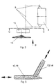
- Fig. 3 In principle, this friction process is shown in Fig. 3.
- the handwheel 10 is arranged on the drive part 12, which corresponds to a transmission drive shaft 16.
- An output part 13 at the output of the gear 11 corresponds to a gear output shaft 14.
- the gear output shaft 14 is articulated to the spar 7 via a lever 15 and a coupling rod 17 movably arranged thereon according to FIG. Movement of the driven part 13 is only possible if the drive part 12 is moved. Conversely, when force is exerted on the driven part 13, movement of the drive part 12 is impossible or can only be achieved by excessive addition of lubricants.
- this principle is implemented in an endless, continuous movement.
Landscapes
- Engineering & Computer Science (AREA)
- Transportation (AREA)
- Mechanical Engineering (AREA)
- Gear Transmission (AREA)
- Power-Operated Mechanisms For Wings (AREA)
- Transmission Devices (AREA)
- Mechanically-Actuated Valves (AREA)
Abstract
Description
Im verschlossenen und beladenen Zustand liegt das Ladegut auf dem Schieber. Zur Entladung muß der Schieber um seine Lagerung geschwenkt werden, um die Entladeöffnung freizugeben und das Ausfließen des Ladegutes zu ermöglichen.
Im Ausfließprozeß drückt das Ladegut gegen die Verschlußfläche des Schiebers und unterstützt damit den Öffnungsprozeß. Je nach den Fließeigenschaften des Ladegutes und der Ladehöhe im Behälter kann diese Kraft sehr große Werte erreichen und den Schieber unkontrolliert beschleunigen. Wenn das Ladegut ausgeflossen ist, hat der Schieber durch die Schwenkbewegung eine große Schrägstellung erreicht. Durch sein Eigengewicht entsteht eine Kraft, die den Schieber wieder zurücklaufen lassen würde. Dieses selbsttätige Zurücklaufen wird durch geeignete mechanische Sperren verhindert, die manuell gelöst werden müssen. Um die Schwenkbewegung zu erzeugen, muß am Schieber ein Drehmoment aufgebracht werden. Die für das Drehmoment notwendige Kraft wird durch Muskelkraft oder elektrische, hydraulische oder pneumatische Hilfsenergie erzeugt. In Abhängigkeit der zur Verfügung stehenden Energiearten kann auch eine Kombination aus den vorgenannten Möglichkeiten zum Einsatz kommen.

Mit der Anordnung eines solchen Getriebes wird erreicht, dass einerseits das Ladegut und andererseits die Gewichtskraft des Schiebers keine beschleunigende Wirkung auf den Verschlußantrieb ausüben kann, die Bauteile vor Überbeanspruchung geschützt und das Bedienen des Antriebes für das Personal sicherer gestaltet werden.
- Fig. 1:
- eine Seitenansicht des Schüttgutwagens,
- Fig. 2:
- die Draufsicht auf den schematisch dargestellten Antrieb der Verschlußeinrichtung,
- Fig. 3:
- eine Einzelheit aus dem Getriebeausschnitt,
- Fig. 4:
- die Ansicht B nach Fig. 2,
- Fig. 5:
- den Schnitt C-C nach Fig. 2.
Prinzipiell ist dieser Reibungsvorgang in Fig. 3 dargestellt. Das Handrad 10 ist an dem Antriebsteil 12 angeordnet, das einer Getriebe-Antriebswelle 16 entspricht. Ein Abtriebsteil 13 am Ausgang des Getriebes 11 entspricht einer Getriebe-Abtriebswelle 14. Die Getriebe-Abtriebswelle 14 ist nach Fig. 5 über einen Hebel 15 und einer daran beweglich angeordneten Koppelstange 17 mit dem Holm 7 gelenkig verbunden. Eine Bewegung des Abtriebsteiles 13 ist nur möglich, wenn das Antriebsteil 12 bewegt wird. Umgekehrt, bei Kraftausübung auf das Abtriebsteil 13 ist eine Bewegung des Antriebsteiles 12 unmöglich oder nur durch überhöhte Zugabe von Schmiermitteln erreichbar. Bei der Verwendung eines bekannten Schneckengetriebes oder extrem schrägverzahnten Stirnradgetriebes ist dieses Prinzip in eine endlose, kontinuierliche Bewegung umgesetzt.
- 1
- Behälter
- 2
- Dach (schwenkbar)
- 3
- trichterförmige Öffnung
- 4
- Schieber (schwenkbar)
- 5
- Lagerung
- 6
- Verschlußfläche
- 7
- Holme
- 8
- Entladeöffnung
- 9
- Kraftübertragungsglied
- 10
- Handrad
- 11
- Getriebe
- 12
- Antriebsteil
- 13
- Abtriebsteil
- 14
- Getriebe-Abtriebswelle
- 15
- Hebel
- 16
- Getriebe-Antriebswelle
- 17
- Koppelstange
Claims (3)
- Antriebseinrichtung für die untere Entladeöffnung (8) von Schüttgutwagen, bestehend aus Verschlußschieber (4), mechanischen Kraftübertragungsgliedern (9), Handrad (10) [Krafteinleitungsstelle] und Getriebe (11), dadurch gekennzeichnet, daß das zwischen Kraftübertragungsgliedern (9) eines Verschlußschiebers (4) und einem Handrad (10) angeordnete Getriebe (11) als selbsthemmendes Getriebe (11) ausgebildet ist.
- Antrieb von Verschlußeinrichtungen nach Anspruch 1, dadurch gekennzeichnet, daß das Getriebe (11) aus einem Zahnradgetriebe besteht.
- Antrieb nach Anspruch 1 und 2, dadurch gekennzeichnet, daß die sich gegenüberliegenden Zahnflanken des selbsthemmenden Getriebes (11) unterschiedliche Rauheitsgrade aufweisen.
Applications Claiming Priority (2)
| Application Number | Priority Date | Filing Date | Title |
|---|---|---|---|
| DE19935577 | 1999-08-01 | ||
| DE19935577A DE19935577C2 (de) | 1999-08-01 | 1999-08-01 | Antriebseinrichtung für die Entladeöffnung von Schüttgutwagen |
Publications (2)
| Publication Number | Publication Date |
|---|---|
| EP1078836A1 true EP1078836A1 (de) | 2001-02-28 |
| EP1078836B1 EP1078836B1 (de) | 2004-04-14 |
Family
ID=7916440
Family Applications (1)
| Application Number | Title | Priority Date | Filing Date |
|---|---|---|---|
| EP00250232A Expired - Lifetime EP1078836B1 (de) | 1999-08-01 | 2000-07-13 | Antriebseinrichtung für die Entladeöffnung von Schüttgutwagen |
Country Status (5)
| Country | Link |
|---|---|
| EP (1) | EP1078836B1 (de) |
| CZ (1) | CZ294080B6 (de) |
| DE (2) | DE19935577C2 (de) |
| PL (1) | PL341782A1 (de) |
| SK (1) | SK11332000A3 (de) |
Cited By (2)
| Publication number | Priority date | Publication date | Assignee | Title |
|---|---|---|---|---|
| CN106516571A (zh) * | 2016-11-28 | 2017-03-22 | 大唐环境产业集团股份有限公司 | 长距离索道运输方法 |
| EP3434551A1 (de) * | 2017-07-27 | 2019-01-30 | WBN Waggonbau Niesky GmbH | Betätigungsmechanismus einer entladeklappe eines schüttgutbehälters |
Families Citing this family (1)
| Publication number | Priority date | Publication date | Assignee | Title |
|---|---|---|---|---|
| RU2592159C2 (ru) * | 2013-06-18 | 2016-07-20 | ОБЩЕСТВО С ОГРАНИЧЕННОЙ ОТВЕТСТВЕННОСТЬЮ "Головное специализированное конструкторское бюро вагоностроения имени Валерия Михайловича Бубнова" | Устройство открывания и закрывания крышек разгрузочных люков бункерного вагона |
Citations (5)
| Publication number | Priority date | Publication date | Assignee | Title |
|---|---|---|---|---|
| GB346127A (en) * | 1930-03-13 | 1931-04-09 | Russell Bailey | Operating gear for bottom doors of railway vehicles |
| US3405655A (en) * | 1966-11-22 | 1968-10-15 | Continental Transp Appliances | Railway hopper car door operating mechanism lock |
| US3447485A (en) * | 1967-01-09 | 1969-06-03 | Continental Transport Applianc | Hopper car door actuating mechanism |
| GB2081198A (en) * | 1980-07-18 | 1982-02-17 | Gloucester Railway Carriage | Hopper Door Mechanisms, e.g. for Railway Wagons |
| DE29913065U1 (de) * | 1999-08-01 | 1999-11-25 | DWA Deutsche Waggonbau GmbH, 12526 Berlin | Antriebseinrichtung für die Entladeöffnung von Schüttgutwagen |
Family Cites Families (2)
| Publication number | Priority date | Publication date | Assignee | Title |
|---|---|---|---|---|
| DE316537C (de) * | ||||
| DE19820542B4 (de) * | 1998-05-08 | 2007-04-12 | Adam Opel Ag | Pedal und Pedalanordnung |
-
1999
- 1999-08-01 DE DE19935577A patent/DE19935577C2/de not_active Expired - Fee Related
-
2000
- 2000-07-13 DE DE50002425T patent/DE50002425D1/de not_active Expired - Lifetime
- 2000-07-13 EP EP00250232A patent/EP1078836B1/de not_active Expired - Lifetime
- 2000-07-25 CZ CZ20002719A patent/CZ294080B6/cs not_active IP Right Cessation
- 2000-07-28 SK SK1133-2000A patent/SK11332000A3/sk unknown
- 2000-07-31 PL PL00341782A patent/PL341782A1/xx not_active Application Discontinuation
Patent Citations (5)
| Publication number | Priority date | Publication date | Assignee | Title |
|---|---|---|---|---|
| GB346127A (en) * | 1930-03-13 | 1931-04-09 | Russell Bailey | Operating gear for bottom doors of railway vehicles |
| US3405655A (en) * | 1966-11-22 | 1968-10-15 | Continental Transp Appliances | Railway hopper car door operating mechanism lock |
| US3447485A (en) * | 1967-01-09 | 1969-06-03 | Continental Transport Applianc | Hopper car door actuating mechanism |
| GB2081198A (en) * | 1980-07-18 | 1982-02-17 | Gloucester Railway Carriage | Hopper Door Mechanisms, e.g. for Railway Wagons |
| DE29913065U1 (de) * | 1999-08-01 | 1999-11-25 | DWA Deutsche Waggonbau GmbH, 12526 Berlin | Antriebseinrichtung für die Entladeöffnung von Schüttgutwagen |
Cited By (3)
| Publication number | Priority date | Publication date | Assignee | Title |
|---|---|---|---|---|
| CN106516571A (zh) * | 2016-11-28 | 2017-03-22 | 大唐环境产业集团股份有限公司 | 长距离索道运输方法 |
| CN106516571B (zh) * | 2016-11-28 | 2019-04-02 | 大唐环境产业集团股份有限公司 | 长距离索道运输方法 |
| EP3434551A1 (de) * | 2017-07-27 | 2019-01-30 | WBN Waggonbau Niesky GmbH | Betätigungsmechanismus einer entladeklappe eines schüttgutbehälters |
Also Published As
| Publication number | Publication date |
|---|---|
| CZ20002719A3 (cs) | 2001-03-14 |
| SK11332000A3 (sk) | 2001-06-11 |
| PL341782A1 (en) | 2001-02-12 |
| DE19935577C2 (de) | 2002-07-11 |
| DE19935577A1 (de) | 2001-03-01 |
| EP1078836B1 (de) | 2004-04-14 |
| DE50002425D1 (de) | 2003-07-10 |
| CZ294080B6 (cs) | 2004-09-15 |
Similar Documents
| Publication | Publication Date | Title |
|---|---|---|
| CH631123A5 (de) | Lastkraftwagen mit ladepritsche und aufbau. | |
| AT500017A1 (de) | Schwenkschiebetür für fahrzeuge | |
| DE3786850T2 (de) | Einrichtung zum Be- und Entladen von palettierten Gegenständen in und aus wärmeisolierten Lieferwagen oder Containern. | |
| EP1460218A2 (de) | Verschlussvorrichtung | |
| EP1078836B1 (de) | Antriebseinrichtung für die Entladeöffnung von Schüttgutwagen | |
| DE4240140A1 (de) | Vorrichtung zum Öffnen und Schließen eines Lukendeckels an einem Kampffahrzeug, insbesondere einem Kampfpanzer | |
| DE29913065U1 (de) | Antriebseinrichtung für die Entladeöffnung von Schüttgutwagen | |
| AT506920B1 (de) | Selbstverriegelnder türantrieb | |
| DE19850805B4 (de) | Feststelleinrichtung für Schiebewände oder Haubenverdecke von Güterwagen | |
| DE20109101U1 (de) | Antrieb für Verschlusseinrichtungen von Schüttgutwagen | |
| DE3926186C2 (de) | Sicherheitsverriegelung für Türen oder Klappen von kastenförmigen Fahrzeugaufbauten oder Containern | |
| DE2637873A1 (de) | Transportfahrzeug fuer einseitig offene behaelter | |
| DE29611395U1 (de) | Elektromechanische Antriebsvorrichtung für eine Drehsäule zur Bewegung eines Schwenktürflügels an einem Fahrzeug | |
| EP2845822A1 (de) | Transportbehälter und System damit | |
| DE819819C (de) | Fahrzeug zum Befoerdern von Gegenstaenden, insbesondere von mit Rollen versehenen Versandbehaeltern | |
| DE756911C (de) | Vorrichtung an Kippgefaessen von Foerderwagen zur Sicherung gegen unbeabsichtigtes Zurueckfallen des Gefaesses aus der Belade- in die Kippstellung | |
| DE102018133301A1 (de) | Schloss für ein Kraftfahrzeug | |
| DE711546C (de) | Schneckenradverschluss fuer Sattelbodenselbstentlader | |
| EP3572056A1 (de) | Tragenlagerungseinrichtung | |
| DE202016005712U1 (de) | Einrichtung zum lösbaren Feststelle von Cargo-Toren an LKW- oder Transporter Aufbauten gegenüber einer Fangvorrichtung | |
| DE1206005B (de) | Klappenverschluss fuer Sattelschuettgutwagen | |
| DE7533632U (de) | An einem Lastfahrzeug angeordnete Ladebordwand | |
| AT401645B (de) | Hub- kippvorrichtung zum entleeren von müllbehältern, insbesondere für müllfahrzeuge | |
| EP0626046A1 (de) | Lineare verstelleinrichtung mit einer überlastsicherung, sowie ein treppenlift. | |
| DE7022938U (de) | Vorrichtung zur sperrung der schwenkfenster von kraftfahrzeugen |
Legal Events
| Date | Code | Title | Description |
|---|---|---|---|
| PUAI | Public reference made under article 153(3) epc to a published international application that has entered the european phase |
Free format text: ORIGINAL CODE: 0009012 |
|
| AK | Designated contracting states |
Kind code of ref document: A1 Designated state(s): AT BE CH LI |
|
| AX | Request for extension of the european patent |
Free format text: AL;LT;LV;MK;RO;SI |
|
| 17P | Request for examination filed |
Effective date: 20010717 |
|
| 17Q | First examination report despatched |
Effective date: 20010924 |
|
| AKX | Designation fees paid |
Free format text: AT BE CH LI |
|
| RBV | Designated contracting states (corrected) |
Designated state(s): DE FR IT |
|
| GRAH | Despatch of communication of intention to grant a patent |
Free format text: ORIGINAL CODE: EPIDOS IGRA |
|
| GRAH | Despatch of communication of intention to grant a patent |
Free format text: ORIGINAL CODE: EPIDOS IGRA |
|
| GRAA | (expected) grant |
Free format text: ORIGINAL CODE: 0009210 |
|
| AK | Designated contracting states |
Designated state(s): DE FR IT |
|
| REF | Corresponds to: |
Ref document number: 50002425 Country of ref document: DE Date of ref document: 20030710 Kind code of ref document: P |
|
| PUAC | Information related to the publication of a b1 document modified or deleted |
Free format text: ORIGINAL CODE: 0009299EPPU |
|
| DB1 | Publication of patent cancelled | ||
| GRAA | (expected) grant |
Free format text: ORIGINAL CODE: 0009210 |
|
| AK | Designated contracting states |
Kind code of ref document: B1 Designated state(s): DE FR IT |
|
| PGFP | Annual fee paid to national office [announced via postgrant information from national office to epo] |
Ref country code: FR Payment date: 20040721 Year of fee payment: 5 |
|
| ET | Fr: translation filed | ||
| PLBE | No opposition filed within time limit |
Free format text: ORIGINAL CODE: 0009261 |
|
| STAA | Information on the status of an ep patent application or granted ep patent |
Free format text: STATUS: NO OPPOSITION FILED WITHIN TIME LIMIT |
|
| 26N | No opposition filed |
Effective date: 20050117 |
|
| PG25 | Lapsed in a contracting state [announced via postgrant information from national office to epo] |
Ref country code: IT Free format text: LAPSE BECAUSE OF NON-PAYMENT OF DUE FEES;WARNING: LAPSES OF ITALIAN PATENTS WITH EFFECTIVE DATE BEFORE 2007 MAY HAVE OCCURRED AT ANY TIME BEFORE 2007. THE CORRECT EFFECTIVE DATE MAY BE DIFFERENT FROM THE ONE RECORDED. Effective date: 20050713 |
|
| PG25 | Lapsed in a contracting state [announced via postgrant information from national office to epo] |
Ref country code: FR Free format text: LAPSE BECAUSE OF NON-PAYMENT OF DUE FEES Effective date: 20050731 |
|
| REG | Reference to a national code |
Ref country code: FR Ref legal event code: ST Effective date: 20080930 |
|
| REG | Reference to a national code |
Ref country code: DE Ref legal event code: R081 Ref document number: 50002425 Country of ref document: DE Owner name: WBN WAGGONBAU NIESKY GMBH, DE Free format text: FORMER OWNER: DB WAGGONBAU NIESKY GMBH, 02906 NIESKY, DE Effective date: 20140730 |
|
| PGFP | Annual fee paid to national office [announced via postgrant information from national office to epo] |
Ref country code: DE Payment date: 20180725 Year of fee payment: 19 |
|
| REG | Reference to a national code |
Ref country code: DE Ref legal event code: R119 Ref document number: 50002425 Country of ref document: DE |
|
| PG25 | Lapsed in a contracting state [announced via postgrant information from national office to epo] |
Ref country code: DE Free format text: LAPSE BECAUSE OF NON-PAYMENT OF DUE FEES Effective date: 20200201 |