EP1077462A2 - Aulöseeinrichtung für einen elektrischen Installationsschalter - Google Patents
Aulöseeinrichtung für einen elektrischen Installationsschalter Download PDFInfo
- Publication number
- EP1077462A2 EP1077462A2 EP00117417A EP00117417A EP1077462A2 EP 1077462 A2 EP1077462 A2 EP 1077462A2 EP 00117417 A EP00117417 A EP 00117417A EP 00117417 A EP00117417 A EP 00117417A EP 1077462 A2 EP1077462 A2 EP 1077462A2
- Authority
- EP
- European Patent Office
- Prior art keywords
- adjusting screw
- tripping device
- slide
- plate
- spindle
- Prior art date
- Legal status (The legal status is an assumption and is not a legal conclusion. Google has not performed a legal analysis and makes no representation as to the accuracy of the status listed.)
- Granted
Links
- 238000009434 installation Methods 0.000 claims description 4
- 238000006073 displacement reaction Methods 0.000 claims description 3
- 238000010616 electrical installation Methods 0.000 claims 1
- 238000000034 method Methods 0.000 description 4
- 230000002093 peripheral effect Effects 0.000 description 2
- 230000002441 reversible effect Effects 0.000 description 2
- 210000001520 comb Anatomy 0.000 description 1
- 238000004519 manufacturing process Methods 0.000 description 1
- 239000000463 material Substances 0.000 description 1
- 238000000465 moulding Methods 0.000 description 1
- 229910001285 shape-memory alloy Inorganic materials 0.000 description 1
Images



Classifications
-
- H—ELECTRICITY
- H01—ELECTRIC ELEMENTS
- H01H—ELECTRIC SWITCHES; RELAYS; SELECTORS; EMERGENCY PROTECTIVE DEVICES
- H01H71/00—Details of the protective switches or relays covered by groups H01H73/00 - H01H83/00
- H01H71/74—Means for adjusting the conditions under which the device will function to provide protection
- H01H71/7427—Adjusting only the electrothermal mechanism
Definitions
- thermobimetal or part of the thermobimetal is deformed. Even with this type of adjustment, the adjustment process is not reversible, d. H. not repeatable any number of times.
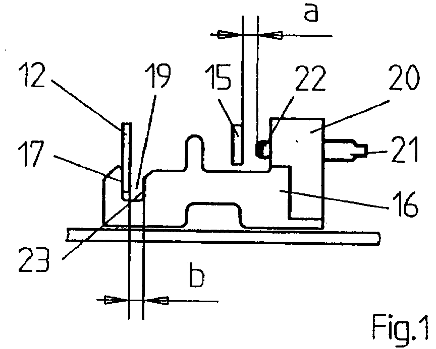
- the bimetal 15 bends and its free end looks up Replace the lead time I against the screw 21, 22, pulls the slide right until the nose 17 bears against the release lever 12 and continues until the latching point 11 is unlatched in the key switch 10.
Landscapes
- Breakers (AREA)
- Thermally Actuated Switches (AREA)
- Push-Button Switches (AREA)
- Driving Mechanisms And Operating Circuits Of Arc-Extinguishing High-Tension Switches (AREA)
- Keying Circuit Devices (AREA)
Abstract
Description
- Fig. 1
- eine Seitenansicht eines Schiebers,
- Fig. 2
- eine Aufsicht auf den Schieber mit Schaltschloß und Thermobimetall, jeweils in der nicht ausgelösten Stellung,
- Fig. 3 bis 8
- die Anordnung gemäß den Fig. 1 und 2 bei unterschiedlichen Justierstellungen,
- Fig. 9
- eine Einsicht in einen Teilbereich eines Gehäuses eines Installationsschaltgerätes im Bereich des Schiebers gemäß einer weiteren Ausführungsform der Erfindung,
- Fig. 10
- eine Ansicht gemäß Pfeilrichtung X der Fig. 9, und
- Fig. 11 bis 13
- unterschiedliche Ansichten einer weiteren Ausgestaltung der Erfindung.
Claims (12)
- Auslöseeinrichtung für einen elektrischen Installationsschalter, insbesondere für einen Leitungsschutzschalter, mit einem thermischen Auslöser, insbesondere mit einem Thermobimetall, der über einen im Schalter verlaufenden, beweglich geführten Schieber eine Verklinkungsstelle eines Schaltschlosses entklinkt, dadurch gekennzeichnet, daß am Schieber (16) eine Justierschraube (22) gelagert ist, mit der die Abstände zwischen dem thermischen Auslöser (15) und dem Schieber (16) einerseits und dem Schieber (16) und einem mit der Verklinkungsstelle (11) zusammenwirkenden Auslösehebel (12) justierbar sind.
- Auslöseeinrichtung nach Anspruch 1, dadurch gekennzeichnet, daß am Schieber (16) eine Hülse (20) mit Innengewinde befestigt oder angeformt ist, in der die Justierschraube (21) eingeschraubt ist.
- Auslöseeinrichtung nach Anspruch 1, dadurch gekennzeichnet, daß am Schieber (92) die Justierschraube (97) unverschieblich drehbar gelagert ist, mit deren Außengewinde (99) eine Platte (100) mit Innengewinde zusammenwirkt, dergestalt, daß die Platte (100) durch Verdrehen der Justierschraube (97) axial bezogen auf die Justierschraube (97) verschiebbar ist, so daß der Abstand zwischen dem thermischen Auslöser (15) und der Angriffsstelle des thermischen Auslösers (15) am Schieber (92) verstellbar ist.
- Auslöseeinrichtung nach Anspruch 3, dadurch gekennzeichnet, daß am Schieber (92) ein zwischen zwei Gabelzinken (95, 96) befindlicher Schlitz (94) vorgesehen ist, in den die Justierschraube (97) einrastbar ist.
- Auslöseeinrichtung nach Anspruch 4, dadurch gekennzeichnet, daß die Justierschraube einen gewindefreien Abschnitt (98) aufweist, der in den Schlitz (94) einrastbar ist.
- Auslöseeinrichtung nach einem der Ansprüche 3 bis 5, dadurch gekennzeichnet, daß Mittel vorgesehen sind, die eine axiale Verschiebung der Justierschraube beim Verdrehen verhindern.
- Auslöseeinrichtung nach Anspruch 6, dadurch gekennzeichnet, daß die Mittel durch eine Leiste (105) an der Justierschraube (97) und eine entsprechende Ausnehmung (106) im Bereich des Schlitzes dienen.
- Auslöseeinrichtung nach einem der Ansprüche 3 bis 7, dadurch gekennzeichnet, daß der Installationsschalter (90) in seinem Gehäuse eine profilierte Öffnung (104) aufweist, in der die angepaßt profilierte Platte (100) axial verschiebbar ist, wobei sich die Platte nicht verdrehen kann, wenn die Justierschraube (97) verdreht wird, und durch die hindurch die Justierschraube (97) von außen zugänglich ist.
- Auslöseeinrichtung nach einem der vorigen Ansprüche, dadurch gekennzeichnet, dass an der Justierschraube (110) eine mit einem zahnradähnlichen Profil (115) an ihrem Umfang versehene Scheibe (112) angeformt ist und dass parallel zur Justierschraube (110) eine Spindel (116) verläuft, deren Außenumfang ein dem zahnradähnlichen Profil angepaßtes Profil aufweist, wobei die Profile der Justierschraube (110) und der Spindel (116) ineinander kämmen, sodass bei Verdrehen der Spindel (116) Justierschraube (110) verdreht wird.
- Auslöseeinrichtung nach Anspruch 9, dadurch gekennzeichnet, dass Platte (114) eine Erweiterung (118) aufweist, durch die die Spindel (116) zu ihrer Führung hindurchgreift.
- Auslöseeinrichtung nach einem der Ansprüche 9 und 10, dadurch gekennzeichnet, dass die Platte (114) an einer Gehäuse - Innenwand (123) gegen Verdrehen geführt ist.
- Auslöseeinrichtung nach einem der Ansprüche 9 bis 11, dadurch gekennzeichnet, dass die Spindel (116) mittels eines an ihrer inneren Stirnfläche angeformten Zapfens (121) in einer Tasche (122) sowie in einer Öffnung (120) im Gehäuse (90) geführt ist.
Applications Claiming Priority (2)
| Application Number | Priority Date | Filing Date | Title |
|---|---|---|---|
| DE19938965A DE19938965A1 (de) | 1999-08-17 | 1999-08-17 | Auslöseeinrichtung für einen elektrischen Installationsschalter |
| DE19938965 | 1999-08-17 |
Publications (3)
| Publication Number | Publication Date |
|---|---|
| EP1077462A2 true EP1077462A2 (de) | 2001-02-21 |
| EP1077462A3 EP1077462A3 (de) | 2002-12-11 |
| EP1077462B1 EP1077462B1 (de) | 2004-05-06 |
Family
ID=7918661
Family Applications (1)
| Application Number | Title | Priority Date | Filing Date |
|---|---|---|---|
| EP00117417A Expired - Lifetime EP1077462B1 (de) | 1999-08-17 | 2000-08-11 | Auslöseeinrichtung für einen elektrischen Installationsschalter |
Country Status (3)
| Country | Link |
|---|---|
| EP (1) | EP1077462B1 (de) |
| AT (1) | ATE266254T1 (de) |
| DE (2) | DE19938965A1 (de) |
Families Citing this family (1)
| Publication number | Priority date | Publication date | Assignee | Title |
|---|---|---|---|---|
| DE10327379A1 (de) * | 2003-06-18 | 2005-01-05 | Abb Patent Gmbh | Justiereinrichtung zur Einstellung von bestimmten Auslösebedingungen für einen thermischen oder elektromagnetischen Auslöser |
Family Cites Families (6)
| Publication number | Priority date | Publication date | Assignee | Title |
|---|---|---|---|---|
| DE814312C (de) * | 1949-04-02 | 1951-09-20 | Kloeckner Moeller Elek Zitaets | Anordnung zum Eichen von thermischen Ausloesern, z. B. fuer elektrische Schalter |
| US3139497A (en) * | 1960-06-14 | 1964-06-30 | Ite Circuit Breaker Ltd | Thermal shunt for trip units |
| DD203427A1 (de) * | 1982-02-22 | 1983-10-19 | Frank Prasse | Einstellvorrichtung fuer thermischen ueberstromausloeser |
| DE3415226A1 (de) * | 1984-04-21 | 1985-10-31 | Brown, Boveri & Cie Ag, 6800 Mannheim | Thermisches ueberstromrelais mit justierbuegel |
| DE3810043A1 (de) * | 1988-03-22 | 1989-10-05 | Siemens Ag | Verfahren und vorrichtung zum justieren eines bimetallausloesers |
| DE19739821A1 (de) * | 1997-09-11 | 1999-03-18 | Abb Patent Gmbh | Vorrichtung zur Justierung eines thermischen Auslösers insbesondere für einen Leitungsschutzschalter |
-
1999
- 1999-08-17 DE DE19938965A patent/DE19938965A1/de not_active Withdrawn
-
2000
- 2000-08-11 AT AT00117417T patent/ATE266254T1/de not_active IP Right Cessation
- 2000-08-11 DE DE50006308T patent/DE50006308D1/de not_active Expired - Lifetime
- 2000-08-11 EP EP00117417A patent/EP1077462B1/de not_active Expired - Lifetime
Also Published As
| Publication number | Publication date |
|---|---|
| DE19938965A1 (de) | 2001-02-22 |
| ATE266254T1 (de) | 2004-05-15 |
| DE50006308D1 (de) | 2004-06-09 |
| EP1077462A3 (de) | 2002-12-11 |
| EP1077462B1 (de) | 2004-05-06 |
Similar Documents
| Publication | Publication Date | Title |
|---|---|---|
| EP0786162B1 (de) | Elektrische verbindungseinrichtung | |
| EP0749629B1 (de) | Sicherheitsschalter | |
| EP0467075B1 (de) | Band für Türen, Fenster und dergleichen sowie Positionierelement für das Führungsteil eines solchen Bandes | |
| DE19531974C2 (de) | Schalt-Sperrmechanismus für eine Schrauben-Anzieheinrichtung | |
| WO2007115619A1 (de) | Sensor und damit ausgestattetes arbeitsgerät | |
| EP2112304A2 (de) | Schlosseinsatz für ein Glastürschloss | |
| EP0000878A1 (de) | Regelventil, insbesondere thermostatisch geregeltes Ventil | |
| DE4024614C2 (de) | Fenster- oder Türbeschlag | |
| EP0635612B1 (de) | Vorrichtung zur Türverriegelung | |
| DE10106228A1 (de) | Sicherheitsschalter mit Entriegelungsscheibe | |
| EP0585541B1 (de) | Elektrischer Schalter zur Drehzahlregulierung von Motoren | |
| EP4012200B1 (de) | Federbelasteter rastbolzen | |
| EP0683341A2 (de) | Sanitärarmatur | |
| EP1151448B1 (de) | Vorrichtung zum schalten einer elektrischen verbindung, insbesondere scharnierschalter | |
| EP3507508A1 (de) | Drehverschluss zur verbindung von bauteilen | |
| EP1077462A2 (de) | Aulöseeinrichtung für einen elektrischen Installationsschalter | |
| DE10037550A1 (de) | Kabelanschlussvorrichtung | |
| EP2034109B1 (de) | Rosetteneinrichtung mit einer Sicherungseinrichtung | |
| DE19614666C2 (de) | Einrichtung zur Betätigung von Türen, Fenstern oder dergleichen | |
| EP0941549B1 (de) | Sicherheitsschalter | |
| EP0569931B1 (de) | Handgriff | |
| DE10321354A1 (de) | Schloss mit längeneinstellbarer Falle | |
| DE29914473U1 (de) | Scharnier | |
| DE29803239U1 (de) | Türschließvorrichtung | |
| AT409519B (de) | Scharnier |
Legal Events
| Date | Code | Title | Description |
|---|---|---|---|
| PUAI | Public reference made under article 153(3) epc to a published international application that has entered the european phase |
Free format text: ORIGINAL CODE: 0009012 |
|
| AK | Designated contracting states |
Kind code of ref document: A2 Designated state(s): AT BE CH CY DE DK ES FI FR GB GR IE IT LI LU MC NL PT SE |
|
| AX | Request for extension of the european patent |
Free format text: AL;LT;LV;MK;RO;SI PAYMENT 20000831 |
|
| RAP1 | Party data changed (applicant data changed or rights of an application transferred) |
Owner name: ABB PATENT GMBH |
|
| PUAL | Search report despatched |
Free format text: ORIGINAL CODE: 0009013 |
|
| AK | Designated contracting states |
Kind code of ref document: A3 Designated state(s): AT BE CH CY DE DK ES FI FR GB GR IE IT LI LU MC NL PT SE |
|
| AX | Request for extension of the european patent |
Free format text: AL;LT;LV;MK;RO;SI PAYMENT 20000831 |
|
| 17P | Request for examination filed |
Effective date: 20021213 |
|
| 17Q | First examination report despatched |
Effective date: 20030121 |
|
| AKX | Designation fees paid |
Designated state(s): AT BE CH CY DE DK ES FI FR GB GR IE IT LI LU MC NL PT SE |
|
| AXX | Extension fees paid |
Extension state: SI Payment date: 20000831 |
|
| GRAP | Despatch of communication of intention to grant a patent |
Free format text: ORIGINAL CODE: EPIDOSNIGR1 |
|
| GRAS | Grant fee paid |
Free format text: ORIGINAL CODE: EPIDOSNIGR3 |
|
| GRAA | (expected) grant |
Free format text: ORIGINAL CODE: 0009210 |
|
| AK | Designated contracting states |
Kind code of ref document: B1 Designated state(s): AT BE CH CY DE DK ES FI FR GB GR IE IT LI LU MC NL PT SE |
|
| AX | Request for extension of the european patent |
Extension state: SI |
|
| PG25 | Lapsed in a contracting state [announced via postgrant information from national office to epo] |
Ref country code: IE Free format text: LAPSE BECAUSE OF FAILURE TO SUBMIT A TRANSLATION OF THE DESCRIPTION OR TO PAY THE FEE WITHIN THE PRESCRIBED TIME-LIMIT Effective date: 20040506 Ref country code: CY Free format text: LAPSE BECAUSE OF FAILURE TO SUBMIT A TRANSLATION OF THE DESCRIPTION OR TO PAY THE FEE WITHIN THE PRESCRIBED TIME-LIMIT Effective date: 20040506 Ref country code: NL Free format text: LAPSE BECAUSE OF FAILURE TO SUBMIT A TRANSLATION OF THE DESCRIPTION OR TO PAY THE FEE WITHIN THE PRESCRIBED TIME-LIMIT Effective date: 20040506 Ref country code: FI Free format text: LAPSE BECAUSE OF FAILURE TO SUBMIT A TRANSLATION OF THE DESCRIPTION OR TO PAY THE FEE WITHIN THE PRESCRIBED TIME-LIMIT Effective date: 20040506 |
|
| REG | Reference to a national code |
Ref country code: GB Ref legal event code: FG4D Free format text: NOT ENGLISH |
|
| REG | Reference to a national code |
Ref country code: CH Ref legal event code: EP |
|
| REF | Corresponds to: |
Ref document number: 50006308 Country of ref document: DE Date of ref document: 20040609 Kind code of ref document: P |
|
| REG | Reference to a national code |
Ref country code: IE Ref legal event code: FG4D Free format text: GERMAN |
|
| GBT | Gb: translation of ep patent filed (gb section 77(6)(a)/1977) |
Effective date: 20040603 |
|
| PG25 | Lapsed in a contracting state [announced via postgrant information from national office to epo] |
Ref country code: SE Free format text: LAPSE BECAUSE OF FAILURE TO SUBMIT A TRANSLATION OF THE DESCRIPTION OR TO PAY THE FEE WITHIN THE PRESCRIBED TIME-LIMIT Effective date: 20040806 Ref country code: GR Free format text: LAPSE BECAUSE OF FAILURE TO SUBMIT A TRANSLATION OF THE DESCRIPTION OR TO PAY THE FEE WITHIN THE PRESCRIBED TIME-LIMIT Effective date: 20040806 Ref country code: DK Free format text: LAPSE BECAUSE OF FAILURE TO SUBMIT A TRANSLATION OF THE DESCRIPTION OR TO PAY THE FEE WITHIN THE PRESCRIBED TIME-LIMIT Effective date: 20040806 |
|
| PG25 | Lapsed in a contracting state [announced via postgrant information from national office to epo] |
Ref country code: LU Free format text: LAPSE BECAUSE OF NON-PAYMENT OF DUE FEES Effective date: 20040811 Ref country code: AT Free format text: LAPSE BECAUSE OF NON-PAYMENT OF DUE FEES Effective date: 20040811 |
|
| PG25 | Lapsed in a contracting state [announced via postgrant information from national office to epo] |
Ref country code: ES Free format text: LAPSE BECAUSE OF FAILURE TO SUBMIT A TRANSLATION OF THE DESCRIPTION OR TO PAY THE FEE WITHIN THE PRESCRIBED TIME-LIMIT Effective date: 20040817 |
|
| PG25 | Lapsed in a contracting state [announced via postgrant information from national office to epo] |
Ref country code: CH Free format text: LAPSE BECAUSE OF NON-PAYMENT OF DUE FEES Effective date: 20040831 Ref country code: LI Free format text: LAPSE BECAUSE OF NON-PAYMENT OF DUE FEES Effective date: 20040831 Ref country code: MC Free format text: LAPSE BECAUSE OF NON-PAYMENT OF DUE FEES Effective date: 20040831 Ref country code: BE Free format text: LAPSE BECAUSE OF NON-PAYMENT OF DUE FEES Effective date: 20040831 |
|
| NLV1 | Nl: lapsed or annulled due to failure to fulfill the requirements of art. 29p and 29m of the patents act | ||
| ET | Fr: translation filed | ||
| REG | Reference to a national code |
Ref country code: IE Ref legal event code: FD4D |
|
| BERE | Be: lapsed |
Owner name: ABB PATENT G.M.B.H. Effective date: 20040831 |
|
| PLBE | No opposition filed within time limit |
Free format text: ORIGINAL CODE: 0009261 |
|
| STAA | Information on the status of an ep patent application or granted ep patent |
Free format text: STATUS: NO OPPOSITION FILED WITHIN TIME LIMIT |
|
| REG | Reference to a national code |
Ref country code: CH Ref legal event code: PL |
|
| 26N | No opposition filed |
Effective date: 20050208 |
|
| BERE | Be: lapsed |
Owner name: *ABB PATENT G.M.B.H. Effective date: 20040831 |
|
| PG25 | Lapsed in a contracting state [announced via postgrant information from national office to epo] |
Ref country code: PT Free format text: LAPSE BECAUSE OF NON-PAYMENT OF DUE FEES Effective date: 20041006 |
|
| PGFP | Annual fee paid to national office [announced via postgrant information from national office to epo] |
Ref country code: DE Payment date: 20130821 Year of fee payment: 14 |
|
| PGFP | Annual fee paid to national office [announced via postgrant information from national office to epo] |
Ref country code: GB Payment date: 20130821 Year of fee payment: 14 |
|
| REG | Reference to a national code |
Ref country code: DE Ref legal event code: R119 Ref document number: 50006308 Country of ref document: DE |
|
| GBPC | Gb: european patent ceased through non-payment of renewal fee |
Effective date: 20140811 |
|
| REG | Reference to a national code |
Ref country code: DE Ref legal event code: R119 Ref document number: 50006308 Country of ref document: DE Effective date: 20150303 |
|
| PG25 | Lapsed in a contracting state [announced via postgrant information from national office to epo] |
Ref country code: GB Free format text: LAPSE BECAUSE OF NON-PAYMENT OF DUE FEES Effective date: 20140811 Ref country code: DE Free format text: LAPSE BECAUSE OF NON-PAYMENT OF DUE FEES Effective date: 20150303 |
|
| REG | Reference to a national code |
Ref country code: FR Ref legal event code: PLFP Year of fee payment: 17 |
|
| PGFP | Annual fee paid to national office [announced via postgrant information from national office to epo] |
Ref country code: FR Payment date: 20160822 Year of fee payment: 17 |
|
| REG | Reference to a national code |
Ref country code: FR Ref legal event code: ST Effective date: 20180430 |
|
| PG25 | Lapsed in a contracting state [announced via postgrant information from national office to epo] |
Ref country code: FR Free format text: LAPSE BECAUSE OF NON-PAYMENT OF DUE FEES Effective date: 20170831 |
|
| PGFP | Annual fee paid to national office [announced via postgrant information from national office to epo] |
Ref country code: IT Payment date: 20190829 Year of fee payment: 20 |