EP1074688A2 - Druckempfindliche Vorrichtung zur Blockierung elektrisch angetriebener beweglicher Schliessvorrichtungen - Google Patents
Druckempfindliche Vorrichtung zur Blockierung elektrisch angetriebener beweglicher Schliessvorrichtungen Download PDFInfo
- Publication number
- EP1074688A2 EP1074688A2 EP00116364A EP00116364A EP1074688A2 EP 1074688 A2 EP1074688 A2 EP 1074688A2 EP 00116364 A EP00116364 A EP 00116364A EP 00116364 A EP00116364 A EP 00116364A EP 1074688 A2 EP1074688 A2 EP 1074688A2
- Authority
- EP
- European Patent Office
- Prior art keywords
- rubber
- profile
- conductive
- parts
- pressure
- Prior art date
- Legal status (The legal status is an assumption and is not a legal conclusion. Google has not performed a legal analysis and makes no representation as to the accuracy of the status listed.)
- Withdrawn
Links
Images

Classifications
-
- E—FIXED CONSTRUCTIONS
- E05—LOCKS; KEYS; WINDOW OR DOOR FITTINGS; SAFES
- E05F—DEVICES FOR MOVING WINGS INTO OPEN OR CLOSED POSITION; CHECKS FOR WINGS; WING FITTINGS NOT OTHERWISE PROVIDED FOR, CONCERNED WITH THE FUNCTIONING OF THE WING
- E05F15/00—Power-operated mechanisms for wings
- E05F15/40—Safety devices, e.g. detection of obstructions or end positions
- E05F15/42—Detection using safety edges
- E05F15/44—Detection using safety edges responsive to changes in electrical conductivity
- E05F15/443—Detection using safety edges responsive to changes in electrical conductivity specially adapted for vehicle windows or roofs
-
- E—FIXED CONSTRUCTIONS
- E05—LOCKS; KEYS; WINDOW OR DOOR FITTINGS; SAFES
- E05Y—INDEXING SCHEME ASSOCIATED WITH SUBCLASSES E05D AND E05F, RELATING TO CONSTRUCTION ELEMENTS, ELECTRIC CONTROL, POWER SUPPLY, POWER SIGNAL OR TRANSMISSION, USER INTERFACES, MOUNTING OR COUPLING, DETAILS, ACCESSORIES, AUXILIARY OPERATIONS NOT OTHERWISE PROVIDED FOR, APPLICATION THEREOF
- E05Y2600/00—Mounting or coupling arrangements for elements provided for in this subclass
- E05Y2600/40—Mounting location; Visibility of the elements
-
- E—FIXED CONSTRUCTIONS
- E05—LOCKS; KEYS; WINDOW OR DOOR FITTINGS; SAFES
- E05Y—INDEXING SCHEME ASSOCIATED WITH SUBCLASSES E05D AND E05F, RELATING TO CONSTRUCTION ELEMENTS, ELECTRIC CONTROL, POWER SUPPLY, POWER SIGNAL OR TRANSMISSION, USER INTERFACES, MOUNTING OR COUPLING, DETAILS, ACCESSORIES, AUXILIARY OPERATIONS NOT OTHERWISE PROVIDED FOR, APPLICATION THEREOF
- E05Y2900/00—Application of doors, windows, wings or fittings thereof
- E05Y2900/50—Application of doors, windows, wings or fittings thereof for vehicles
- E05Y2900/53—Type of wing
- E05Y2900/55—Windows
Definitions
- the invention relates to a device for Stopping the movement of one out of an electric driven closure existing moving element in the event that an object is provided in the Path of said movable element or Closure arrives and through on the device Exerted force causes this one on them acting pressure recognizes.
- the device enables in addition, their self-test or review of Functionality.
- the aim of the invention is a device in the form of an elastomer profile with two at rest separate conductive elements
- To provide a flexible overall arrangement Profile result that both on windows of Motor vehicles, their windows by electrical Operation to be closed as on doors of Elevators, shutters in the domestic and industrial sector, Garage doors as well as generally in each other practical case is applicable, in which there is a given the time may be necessary movable closing element at each on the device block acting pressure, this pressure is detected by pinching the head or hand a person, for example, while closing one To prevent vehicle window.
- said Device one on the current flow through the profile self-resting safety element in automatic represents closing facilities with a bistable value of the current below one minimum threshold or above a maximum Threshold, which also means for the Self test to check the functionality of the Device included at any time.
- European Patent No. 0638701 referring to protection by locking for locking devices with Power drive relates and preferably to electrical operated windows and sunroofs from Motor vehicles is applicable, this is based on Protective effect on a hollow profile that consists of a Is elastomer or plastic material, which Profile has two conductive areas through insulating or non-conductive elements from each other separated and facing each other Bulges are provided so that after installing the Profile in the leadership for example one Vehicle window through one on the edge of the window hand while exerted pressure on the profile the automatic upward movement of the window Cause connection of the two conductive areas and the function can lock, causing one without this Blocking possible accident or jamming is prevented.
- the mentioned device or protective device for Interlocking has two major drawbacks, one of which one is that it is not possible to Check functionality of the device, therefore at no time known whether this occurs when the the aforementioned event takes effect or not.
- the connector is attached to the side that the End opposite, on the aforementioned rubber block was molded on, for example in the case of a Vehicle window.
- Another improvement and object of the invention consists of the intermediate layer of an insulating strand, preferably made of non-conductive rubber, which prevents that the two conductive rubber parts in undesirable when bending and adjusting the profile touch the receiving opening.
- This non-conductive Rubber is preferably in the axis of symmetry Profiles arranged so that its shape and dimensions do not prevent yourself from being under pressure off-center point of the profile the two conductive Touch rubber layers one below the other.
- the Device according to the invention in a conventional manner a profile (1) made of rubber or the like Material that is hollow and a pair inside of elements or parts running in the longitudinal direction (2) made of conductive rubber in this case, wherein these parts, as can be seen from Figure 1, one have a small distance between them and in them Elements or parts (2) conductive wires (3) are embedded, in the vicinity of which a pair of openings (4) for inserting the poles or end pieces (5) one Have connector (6) under pressure, via which Device, in this case the said Profile arrangement, electrically powered and the poles (5) by insertion under pressure into the openings (4) are perfectly connected to the profile arrangement, it is however, it is also possible that these openings (4) in the conductive elements or parts (2) are missing and the Poles at their ends as shown in Figure 1 can be beveled and into the elements or parts (2) can be inserted.
- One of the ends of said profile (1) is always through added a molded rubber block (7), while on other end of the corresponding connector (6) electrical supply is connected.
- the conductors (3) have good conductivity and can consist of a simple metal wire, which the only condition must be that Dimensions are suitable for the design of the profile (1) and the surface is conductive.
- the conductive parts (2) as part of the profile (1) themselves must have such properties that whose electrical resistance is lower than that in the Application is provided, this will only be one thin layer in the vertical direction from one Current on the order of milliamps flowed through.
- the rubber block (7) must also be made of a conductive Material exist and an electrical resistance exhibit that is between a hundred and a thousand times larger is that of the entire arrangement, that is conductive parts (2), this rubber block (7)
- the function of self-examination is fulfilled by having a Current flow on the order of milliamps enables. That is, the electrical circuit will closed about the rubber block (7) and due to its very high resistance flows in the Circuit a very low current, which is proof allows the system, in this case the Device that is ready for operation at any time.
- the conductive parts (2) of the profile (1) and thus those in these parts embedded conductors (3) must be separated from one another, as long as there is no pressure on the profile (1) or is exercised, or, which means the same thing, the Device is at rest.
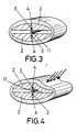
- the Execution takes place so that in the event when a person hands or head on the top of the disc (9) of the window and the locking system or the Window lifter is operated at a slight through the Hand or head exerted pressure on the profile (1), caused by the thrust of the disc (9), the Touch the conductive parts (2) of the profile (1) and thus blocking the function of the system or device cause so that the movement of the disc stops and a Pinching or accident is avoided as it is without said pressure sensitive device could occur.
Landscapes
- Power-Operated Mechanisms For Wings (AREA)
- Pipe Accessories (AREA)
- Window Of Vehicle (AREA)
Abstract
Description
Claims (5)
- Druckempfindliche Vorrichtung zur Blockierung elektrisch angetriebener beweglicher Schließvorrichtungen, anwendbar an Fahrzeugfenstern, Türen von Aufzügen, Rolläden und in sonstigen praktischen Fällen, in denen ein bewegliches automatisch angetriebenes elektrisch gespeistes Schließelement vorhanden ist, mit dem Ziel, die Funktion des beweglichen Schließelements zu sperren, wenn dieses Druck auf ein Objekt ausübt, das die Hand oder der Kopf einer Person sein kann, die sich zwischen besagtem beweglichem Schließelement und der eigentlichen an der Führung des betreffenden Schließelements angebrachten Vorrichtung befindet, bestehend aus einem flexiblen Hohlprofil (1) aus Gummi oder einem ähnlichen Material, in dessen Innerem zwei Teile (2) angeordnet sind, ebenfalls aus Gummimaterial, das jedoch elektrisch leitfähig ist, und in welchen die beiden elektrischen Leiter (3) eingebettet sind, wobei die Gesamtanordnung mit einer äußeren elektrischen Stromversorgung verbunden ist, dadurch gekennzeichnet, daß an einem der Enden des Profils (1) ein Block (7) aus Gummi oder einem thermoplastischen elektrisch gering leitfähigen Material angeformt ist, über welchen der elektrische Stromkreis mit hohem Widerstand für den elektrischen Strom geschlossen wird, so daß durch den Stromkreis ständig ein Strom mit einer sehr geringen Stärke fließt, der die Überprüfung der Funktionsbereitschaft der Vorrichtung ermöglicht.
- Druckempfindliche Vorrichtung zur Blockierung elektrisch angetriebener beweglicher Schließvorrichtungen gemäß Anspruch 1, dadurch gekennzeichnet, daß diese Vorrichtung als Trennelement zwischen den beiden leitfähigen Gummiteilen (2) einen isolierenden Strang (11) aufweist, vorzugsweise aus nichtleitendem Gummi, der einen konstanten Abstand zwischen den beiden leitfähigen Gummiteilen (2) garantiert, wenn das Profil zur Anpassung an die Aufnahmeöffnung gebogen wird, wobei dieser Strang jedoch den Kontakt zwischen den leitfähigen Teilen nicht verhindert, wenn Druck auf einen anderen Punkt als denjenigen ausgeübt wird, an dem der isolierende Strang (11) angeordnet ist.
- Druckempfindliche Vorrichtung zur Blockierung elektrisch angetriebener beweglicher Schließvorrichtungen gemäß den vorhergehenden Ansprüchen, dadurch gekennzeichnet, daß der isolierende Strang (11) die Möglichkeit zu seitlicher Bewegung im Inneren des Profils (1) besitzt, so daß bei Ausüben eines ausreichenden Drucks auf den der Lage des Strangs (11) entsprechenden Bereich des Profils (1) eine seitliche Bewegung dieses Strangs bewirkt wird, die den Kontakt zwischen den leitfähigen Gummiteilen (2) ermöglicht.
- Druckempfindliche Vorrichtung zur Blockierung elektrisch angetriebener beweglicher Schließvorrichtungen gemäß den Ansprüchen 1 und 2, dadurch gekennzeichnet, daß die elektrische Verbindung der elektrischen Leiter (3) mit dem Äußeren über die Pole (5) eines Steckverbinders (6) durch deren Einstecken in den Gummi der leitfähigen Teile oder Elemente (2) oder durch Klemmsitz genannter Pole (5) in hierzu in besagten leitfähigen Teilen oder Elementen (2) angebrachten Öffnungen (4) derart hergestellt wird, daß der elektrische Strom von den elektrischen Leitern (3) durch den Gummi der Teile (2) zu den Polen (5) fließt.
- Druckempfindliche Vorrichtung zur Blockierung elektrisch angetriebener beweglicher Schließvorrichtungen gemäß den vorhergehenden Ansprüchen, dadurch gekennzeichnet, daß der Gummiblock (7) durch Anformen am Profil (1) befestigt ist.
Applications Claiming Priority (2)
| Application Number | Priority Date | Filing Date | Title |
|---|---|---|---|
| ES9901803 | 1999-08-02 | ||
| ES9901803 | 1999-08-02 |
Publications (2)
| Publication Number | Publication Date |
|---|---|
| EP1074688A2 true EP1074688A2 (de) | 2001-02-07 |
| EP1074688A3 EP1074688A3 (de) | 2001-04-04 |
Family
ID=8309558
Family Applications (1)
| Application Number | Title | Priority Date | Filing Date |
|---|---|---|---|
| EP00116364A Withdrawn EP1074688A3 (de) | 1999-08-02 | 2000-07-28 | Druckempfindliche Vorrichtung zur Blockierung elektrisch angetriebener beweglicher Schliessvorrichtungen |
Country Status (2)
| Country | Link |
|---|---|
| EP (1) | EP1074688A3 (de) |
| SK (1) | SK11252000A3 (de) |
Cited By (2)
| Publication number | Priority date | Publication date | Assignee | Title |
|---|---|---|---|---|
| DE102010035692A1 (de) * | 2010-08-27 | 2012-03-01 | Jürgen Menz | Elektrischer Anschluss einer Sicherheitsschalteinrichtung |
| DE102020101952A1 (de) | 2020-01-28 | 2021-07-29 | Bayerische Motoren Werke Aktiengesellschaft | Verfahren zum Bereitstellen eines Einklemmschutzes für ein Kraftfahrzeug |
Family Cites Families (3)
| Publication number | Priority date | Publication date | Assignee | Title |
|---|---|---|---|---|
| DE4329535C2 (de) * | 1993-08-09 | 1998-03-26 | Metzeler Automotive Profiles | Einklemmschutz für kraftbetätigte Schließeinrichtungen |
| DE19502033C1 (de) * | 1995-01-25 | 1996-06-13 | Daimler Benz Ag | Schutzeinrichtung für ein mittels eines Antriebs betätigbares Schließteil eines Kraftfahrzeugs |
| DE19602744C2 (de) * | 1996-01-19 | 1999-04-29 | Mayser Gmbh & Co | Sicherheitsschaltleistenanordnung |
-
2000
- 2000-07-27 SK SK1125-2000A patent/SK11252000A3/sk unknown
- 2000-07-28 EP EP00116364A patent/EP1074688A3/de not_active Withdrawn
Cited By (4)
| Publication number | Priority date | Publication date | Assignee | Title |
|---|---|---|---|---|
| DE102010035692A1 (de) * | 2010-08-27 | 2012-03-01 | Jürgen Menz | Elektrischer Anschluss einer Sicherheitsschalteinrichtung |
| DE102020101952A1 (de) | 2020-01-28 | 2021-07-29 | Bayerische Motoren Werke Aktiengesellschaft | Verfahren zum Bereitstellen eines Einklemmschutzes für ein Kraftfahrzeug |
| DE102020101952B4 (de) * | 2020-01-28 | 2025-06-18 | Bayerische Motoren Werke Aktiengesellschaft | Verfahren zum Bereitstellen eines Einklemmschutzes für ein Kraftfahrzeug |
| US12528416B2 (en) | 2020-01-28 | 2026-01-20 | Bayerische Motoren Werke Aktiengesellschaft | Method for providing anti-trap protection for a motor vehicle |
Also Published As
| Publication number | Publication date |
|---|---|
| SK11252000A3 (sk) | 2001-03-12 |
| EP1074688A3 (de) | 2001-04-04 |
Similar Documents
| Publication | Publication Date | Title |
|---|---|---|
| DE60115320T2 (de) | Einklemmschutz | |
| DE2752432A1 (de) | Rolltor fuer hallen o.dgl. | |
| DE19602744C2 (de) | Sicherheitsschaltleistenanordnung | |
| DE69632372T2 (de) | Kontaktschlauch | |
| DE19836705C2 (de) | Fensterheber mit Einklemmschutz | |
| EP3847332B1 (de) | Schutzvorrichtung für einen türflügel für ein fahrzeug und türvorrichtung für ein fahrzeug | |
| DE3724942A1 (de) | Sicherheitsvorrichtung | |
| DE3424581A1 (de) | Einklemmschutz fuer mit einem elektrisch betaetigbaren fensterheber ausgeruestete fahrzeuge | |
| DE19913106C1 (de) | Einklemmschutz für eine kraftbetätigte Schließeinrichtung | |
| EP3685001A1 (de) | Vorrichtung zum einklemmschutz für eine tür für ein fahrzeug, türsystem für ein fahrzeug und verfahren zum herstellen einer vorrichtung zum einklemmschutz für eine tür für ein fahrzeug | |
| DE19809909B4 (de) | Schiene mit Stromzuführungseinrichtung | |
| DE3618766A1 (de) | Sicherheitsvorrichtung fuer tore oder dgl. | |
| EP0848780B1 (de) | Vorrichtung zur einklemmerkennung | |
| DE10047085B4 (de) | Kraftfahrzeug mit einem Einklemmschutzschalter für eine motorisch verschließbare und/oder verriegelbare Front- oder Heckklappe | |
| EP0195102A1 (de) | Elektrischer Kontaktgeber zur Überwachung einer in einem Gewinde oder nachgiebigem Material eingeschraubten Schraube | |
| DE60203946T2 (de) | Einklemmschutzvorrichtung für automatiktüren, insbesondere von aufzügen | |
| DE60017499T2 (de) | Einklemmschutz für Schiebetür eines Kraftfahrzeuges | |
| DE102006026683A1 (de) | Vorrichtung und Verfahren zum Erkennen eines Einklemmzustands in einer Kraftfahrzeugöffnungseinrichtung | |
| DE69923122T2 (de) | Gerät zur Feststellung von Hindernissen | |
| DE10151840A1 (de) | Vorrichtung und Verfahren zum Verstellen eines Teils | |
| DE19906562B4 (de) | Einklemmsicherung für Fensterheber von Fahrzeugen | |
| DE3411198C2 (de) | ||
| DE3829499A1 (de) | Schliesskantensicherung | |
| DE102015203634B4 (de) | Stromzuführung für einen Tür- oder Fensterflügel | |
| DE8615042U1 (de) | Sicherheitsvorrichtung für Tore od. dgl. |
Legal Events
| Date | Code | Title | Description |
|---|---|---|---|
| PUAI | Public reference made under article 153(3) epc to a published international application that has entered the european phase |
Free format text: ORIGINAL CODE: 0009012 |
|
| AK | Designated contracting states |
Kind code of ref document: A2 Designated state(s): AT BE CH CY DE DK ES FI FR GB GR IE IT LI LU MC NL PT SE |
|
| AX | Request for extension of the european patent |
Free format text: AL;LT;LV;MK;RO;SI |
|
| PUAL | Search report despatched |
Free format text: ORIGINAL CODE: 0009013 |
|
| AK | Designated contracting states |
Kind code of ref document: A3 Designated state(s): AT BE CH CY DE DK ES FI FR GB GR IE IT LI LU MC NL PT SE |
|
| AX | Request for extension of the european patent |
Free format text: AL;LT;LV;MK;RO;SI |
|
| 17P | Request for examination filed |
Effective date: 20011004 |
|
| AKX | Designation fees paid |
Free format text: AT BE CH CY DE DK ES FI FR GB GR IE IT LI LU MC NL PT SE |
|
| 17Q | First examination report despatched |
Effective date: 20020125 |
|
| STAA | Information on the status of an ep patent application or granted ep patent |
Free format text: STATUS: THE APPLICATION HAS BEEN WITHDRAWN |
|
| 18W | Application withdrawn |
Withdrawal date: 20020620 |