EP1074282A2 - Kegelaufsetzvorrichtung - Google Patents
Kegelaufsetzvorrichtung Download PDFInfo
- Publication number
- EP1074282A2 EP1074282A2 EP00116184A EP00116184A EP1074282A2 EP 1074282 A2 EP1074282 A2 EP 1074282A2 EP 00116184 A EP00116184 A EP 00116184A EP 00116184 A EP00116184 A EP 00116184A EP 1074282 A2 EP1074282 A2 EP 1074282A2
- Authority
- EP
- European Patent Office
- Prior art keywords
- cone
- setting unit
- movable part
- counterweight
- holding
- Prior art date
- Legal status (The legal status is an assumption and is not a legal conclusion. Google has not performed a legal analysis and makes no representation as to the accuracy of the status listed.)
- Withdrawn
Links
- 230000007246 mechanism Effects 0.000 claims description 13
- 230000000694 effects Effects 0.000 claims description 2
- 239000000523 sample Substances 0.000 description 5
- 238000000034 method Methods 0.000 description 3
- 238000013016 damping Methods 0.000 description 2
- 210000001015 abdomen Anatomy 0.000 description 1
- 230000015572 biosynthetic process Effects 0.000 description 1
- 230000001427 coherent effect Effects 0.000 description 1
- 238000010276 construction Methods 0.000 description 1
- 230000001419 dependent effect Effects 0.000 description 1
- 238000009434 installation Methods 0.000 description 1
- 238000012986 modification Methods 0.000 description 1
- 230000004048 modification Effects 0.000 description 1
- 239000004033 plastic Substances 0.000 description 1
- 230000000284 resting effect Effects 0.000 description 1
- 230000006641 stabilisation Effects 0.000 description 1
- 238000011105 stabilization Methods 0.000 description 1
Images


Classifications
-
- A—HUMAN NECESSITIES
- A63—SPORTS; GAMES; AMUSEMENTS
- A63D—BOWLING GAMES, e.g. SKITTLES, BOCCE OR BOWLS; INSTALLATIONS THEREFOR; BAGATELLE OR SIMILAR GAMES; BILLIARDS
- A63D5/00—Accessories for bowling-alleys or table alleys
- A63D5/08—Arrangements for setting-up or taking away pins
Definitions
- the invention relates to a cone placing device in a rope-less cone setting machine, which is arranged to move up and down above the cone.
- the cones are scrapped after a ball has been thrown cleared of the playing surface, transported up to a sorting plant and fed through a distribution system to a setting basket, by means of which the cone matches the cone pattern be placed on the cone stand accordingly.
- the cage is a coherent one Formation and it is moved together with the cones down to the cone to be placed on the cone footprint.
- the basket must be actuated each time it is set up, even if only a single cone has to be set up.
- the invention has for its object the necessary to set up the cone Simplify the effort with a rope-less cone setting machine and the cone placement device better adapt to game needs.
- the cone placement device can be easily adapted to any shape of the cone image.
- a single cone setting unit can be replaced without the entire Cone placement device is affected.
- the individual cone setting units are characterized by recurring, The same parts can be produced economically and, in the case of assembly, also easily transport because the individual taper-setting units are assembled individually on site can.
- the configuration of the taper attachment device according to the invention results by means of individual cone setting units with regard to assembly and service simple design that can be easily retrofitted to existing bowling alleys and for everyone Sorting and feeding systems can be used.
- the individual cone setting units can also be easily adapted to the respective cone shapes, so that overall, the cone placement device can be used universally.
- the individual cone setting units are without motor drive moves, which further simplifies the effort.
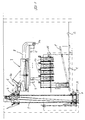
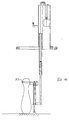
- the cone is 1 as Plate formed that can be raised at the front end, as at 1 'by dash-dotted lines Lines are reproduced so that at the end of a skittles game everyone is still on the skittles located cone are transported into the cone pit 3.
- a collecting trough 4 for receiving the cones and the ball is arranged in the conical pit 3, raised by a lifting device with side guides 5 and at the top End of the lifting device can be emptied by tilting.
- the cones and the ball fall out of the tilted trough 4 into a presorting device 6, from which the cones fall into a sorting device 7, while those of the cones Ke separate ball Ku is discharged laterally.
- Get out of the sorting device 7 the cones individually in a cone channel 8, at the end of a cone by a gripping device 9 is detected and inserted into a cone setting unit 10, which has a cone Ke the cone stand 1.
- the number of cone setting units 10 corresponds to the number of cones to be set up, wherein the individual cone setting units 10 are grouped above the cone level 1 in such a way that after the cone has been deposited by each individual cone setting unit 10, the desired cone image on the cone footprint 1.
- the individual cone setting units 10 can each be opened and closed by a drive device are moved, z. B. an electric drive motor is provided for each cone setting unit can be controlled via a control device.
- the cone setting unit 10 consists of a stationary Part and a moving part.
- the stationary part is on a holder, for example a plate 11 is attached, in the corresponding conical recesses provided through which the movable part is lowered to the cone level 1.
- the stationary part is a Cone setting unit 10 from three guide tubes 12, which are at equal angular intervals around the Recess positioned in the plate 11 and at the top by a ring 13 with each other are connected.
- the guide tubes 12 also positioned at the lower end on a ring 13 '(Fig. 4).
- On the top ring 13 is a radially outwardly protruding bracket 14 is attached, at the outer end of a rope 15th is attached.
- a deflection roller 16 is rotatably mounted on the ring 14 above the ring 13.
- the movable part of the cone setting unit consists of an annular body 17 for receiving the Cone base.
- a cone basket 18 in the form of a tube piece Plastic or the like arranged, which can also be provided with openings, to save weight.
- the movable end of the rope 15 is attached to the ring body 17, that between the stationary pulley 16 and the fixed rope end via a pulley 19 is guided, which is rotatably attached to a counterweight 20.
- That counterweight 20 is schematically in the embodiment of FIGS. 2 to 5 as an annular body shown, which surrounds the guide rods 12.
- is on the receiving the cone foot Ring body 17 is a multi-part, two-part in the illustrated embodiment Fixed telescopic rod 21 which is guided in the guide tube 12.
- the top view of the cone setting unit 10 in FIG. 3 shows that three brackets 14 with a deflection roller 16 arranged on the ring 13 at equal angular intervals between three guide tubes 12 are.
- the cone is not shown in Fig. 3.
- the annular counterweight 20 is by means of magnetic coils 22 held on the plate 11, which are positioned under the plate. 3
- magnetic coils 22 held on the plate 11, which are positioned under the plate. 3
- only two diametrically opposed coils 22 are provided, which are shown in FIG are shown offset.
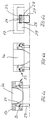
- the cone is in the ring body 17 by two diametrically opposite or three in cam mechanisms 23 arranged at the same angular distances, which are shown in FIGS to 6c are reproduced in detail.
- a holding cam 25 is pivotally supported by an eccentric cam 26 in Fig. 6a is held against the circumference of the conical foot.
- the Eccentric cam 26 is pivotally mounted on the ring body 17 with the outer end, while at the radially inner end of the eccentric cam 26 a probe bracket 27 is articulated which projects beyond the lower boundary surface of the ring body 17.
- By weight of the feeler 27 is the eccentric cam 26 in Fig. 6a on the left side in a clockwise direction pivoted downward, the holding cam 25 is pressed radially inwards and preventing a cone falling from above from falling out of the ring body 17.
- Fig. 6c shows a side view of the cam mechanism, which is in the slot-shaped recess 24 is pivotally mounted via hinge pins, which are in webs 28 of the ring body 17th are used, these webs 28 being formed in a larger recess 29 of the ring body are.
- the cone is kept ready above the cone stand 1, as also shown in Fig. 1.
- the counterweight is used to lower the cone 20 released by the solenoids 22 are de-energized.
- the counterweight 20 is designed so that the movable part of the cone setting unit 10 with a cone is heavier than the counterweight 20, while the movable part of the cone setting unit 10 without the cone is lighter than the counterweight 20.
- the movable part of the cone setting unit 10 also lowers due to the greater weight Cone off, while the counterweight 20 on the pulley 19 by the descending Rope 15 is raised, as shown in FIG. 4.
- the telescopic rod 21 is off the guide tube 12 extended so that the ring body 17 with the in the conical basket 18th arranged cone guided during the lowering movement and on the intended location is placed on the cone stand 1.
- Fig. 6a shows the arrangement immediately when the probe bracket 27 is placed on the cone 1 with cone Ke still held in the annular body 17.
- the ring body 17 becomes part of the cone setting unit 10 with the cone in FIG. 6a further lowered, as shown in FIG. 6b, at the same time pressing the feeler 27 upwards and the eccentric cams 26 are pivoted outward to release the holding cam 25.
- the ring body 17 can be seated on the mounting surface Probe bracket can no longer be moved further down.
- the release process of the Kegel Ke preferably takes place before the cone is placed on the cone stand 1, so that the cone, for example from a height of 2 cm above the cone stand 1 on this falls.
- This drop height is dependent on the appropriate design of the length of the feeler arm 27 of the bulge of the cone foot so designed that by falling down of the cone to the cone level 1 of the holding cams 25 in the place of the largest diameter of the cone foot or to the top of the bulbous shape of the cone comes to rest after in this state there is a relative movement between the ring body 17 and the conical base.
- the cone is stabilized in its standing position, while at the same time releases the weight of the cone from the movable part of the cone setting unit 10 so that it becomes easier.
- the counterweight 20 lowers from the raised position Fig. 4 and pulls the movable part of the cone setting unit 10 again via the rope 15 upwards into the position shown in Fig. 5, in which the cone setting unit 10 over located on the cone stand 1.
- the counterweight 20 on the plate 11 is moved via the magnetic coils 22 determined what the game operation can start while using a feed device, not shown a cone can already be used in stock in the cone basket 18 in FIG. 5 can.
- the eccentric cam 26 is by the weight of the probe bracket 27 pivoted downward and thus the retaining cam 25 radially pressed inwards that a cone falling into the cone basket 18 is held securely.
- the cam surfaces between holding cams 25 and eccentric cams 26 designed so that the holding cam 25 is not by the weight of the cone falling in the cone 18 can be pushed outwards.
- Fig. 5 are both positions of the eccentric cam 26 shown in FIGS. 6a and 6b.
- magnétique coils 22 also other holding devices for the counterweight 20 are provided be, for example mechanical locking devices that have an electrical or mechanical controlled element can be released and locked.
- the shape of the counterweight 20 in a different way.
- a single counterweight can be attached to each deflection roller 19 be, but to synchronize the lifting and lowering movement of the counterweights
- a connecting ring is expediently provided, which holds the individual counterweights connects with each other.
- the bracket 14 on the ring 13 can be designed, for example, from a U-shaped profile can be, the guide roller 14 is rotatably mounted in this U-profile.
- cam mechanism 23 with the feeler 27 can also be used in a different way can be designed to hold the cone in the cone basket 18 securely and to release it when it is in place.
- another releasable holder for the cone can also be used be provided in the cone basket 18.
- a flexible one filled with compressed air Ring 44 can be inserted on the inner circumference of the cone basket 18, as shown in Fig. 12. In the inflated state, the ring 44 holds the cone securely in the cone basket 18.
- For releasing vacuum is applied to the ring 44 via a valve arrangement, not shown, so that its inner circumference increases and the cone to be placed on the cone stand 1 is released.
- a rubber plate can be used in the cone basket 18 be, which is provided with radial incisions to increase its flexibility, so that the cone can easily slide through this rubber plate with an opening in the middle can, while exerting a certain braking force due to friction, so that the cone does not hit the cone stand 1 too hard when moving from the movable one Part of the cone setting unit 10 is released and down over the intended drop height falls.
- a rubber plate arranged in the cone basket also serves as a guide and centering the cone during the touchdown movement and for stabilization after touchdown.
- the lateral guidance of the ring body 17 with the conical basket 18 can also be designed in a different way are considered by the telescopic rods 21 shown in FIGS. 2 to 4 in the guide tube 12.
- the lower part of the rope 15 can be rigid Rod to be replaced, which is guided in a bore of the plate 11, while the upper Section in the form of a rope is designed to be flexible so that section is reduced the height around the pulleys 16 and 19 can be performed.
- a telescopic rod 21 also a rigid guide rod can be provided, which in the raised position of the cone setting unit 10 in Fig. 5 protrudes further up.
- FIGS. 7 to 9 and in FIG. 13 and 14 reproduced.
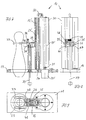
- the stationary part consists of two parallel guide tubes in a structure 30 which is screwed onto the plate 11, in which a guide tube a counterweight 20 'is guided over a rope 15', one end of which is on the upper part the structure 30 is held, while the opposite end after deflection over Deflection rollers 32 is attached to the movable part of the cone setting unit 10, wherein, as Fig. 13 and 14 show the movable rope end at 34 on the lower portion 21 "of the telescopic rod is attached.
- the telescopic rod 21 ', 21' ' is in the other guide tube 12' of the structure 30 guided and forms with the counterweight 20 'and one at the lower end of the telescopic section 21 '' attached bracket 45, on which a guide tube 46 for the button 37 is attached with the gripping jaws 33, the movable part of the cone setting unit 10.
- Two laterally projecting arms 35 are rigidly formed on the stationary structure 30, between the rear portions of the gripper arms 33 to lie in the raised position come so that the gripping arms are held together when picking up a cone and cannot be pushed apart.
- 8 and 9 show the two arms 35 with intermediate gripping jaws.
- a bracket 48, the two arms 35 on the top connects together forms a stop for the gripping arms 33 during the upward movement.
- On this bracket is a locking device for the movable part of the Cone setting unit arranged in the illustrated exemplary embodiment by one of a solenoid 39 operated locking hook 40 is formed, which is in the locking position the component 47 engages behind, as shown in FIGS. 10a and 10b.
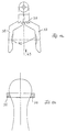
- the protruding length of the button 37 is preferably designed so that the gripping jaws 33 begin to open in the position shown in FIG. 13, so that the cone moves relative to the gripping jaws 33 downward Fallen executes, the movable part of the cone setting unit 10 already its end position has reached by resting the button 37 on the footprint.
- the Gripping jaws 33 to lie in the place of the maximum diameter of the cone head, such as this shows Fig. 14, so that the cone stabilizes in position after and after touchdown while the weight of the cone is moving away from the moving part of the Cone setting unit 10 releases, so that the counterweight 20 'the movable part of the cone setting unit can pull up.
- the button 37 is correspondingly heavy or provided with a weight at the lower end, so that during this stroke movement of the cone setting unit the button 37 drops relative to the gripping jaws 33 and this under the Effect of the spring 38 close over the cone head again.
- This sequence of movements essentially corresponds to that described with reference to FIGS. 2 to 5, with only a single telescopic rod and a single counterweight 20 'as a guide is provided. Also, only one button 37 is required for the gripping jaws 33, while at the previously described embodiment actuates at least two cam mechanisms 23 Need to become.
- a damping element can be installed by releasing the Cone is damped and braked so that it sits softly on the cone stand 1.
- the arrangement is designed so that the cam mechanism 23 or Gripping jaws 33 already slightly above when placing the cone on the cone stand largest diameter of the conical foot or head are because after lifting the movable Part of the cone setting unit 10 by the damping spring, the closing movement of the Cam mechanism 23 or the gripper jaw 23 runs faster.
- a Proximity sensor can be provided on the movable part of the cone setting unit, which in one predetermined distance above the contact surface, for example, by a control signal a solenoid operated holding device for the cone, which in turn in the form of Gripping jaws 33 or in the form of a cam mechanism 23 or in another manner can be.
- the telescopic guide of the cone basket 18 can also be designed in such a way that the Cone basket 18 itself is surrounded by a tubular element, which together with the Cone basket 18 acts as a telescopic device. In this case, single telescopic poles omitted.
- the cone basket 18 can also be made longer, so that it can accommodate, for example, two or three cones arranged one above the other.
- a cone setting unit 10 with a magazine becomes an additional device provided that the lowest cone in the extended cone basket from the ones above Keeps cones separately, so that only after placing the lowest cone on the Advance cone level 1 of the next cone into the ready position according to Fig. 2 can.
- the embodiment of a cone holding device shown in FIG with inflatable ring 44 in the cone basket 18 that can be expanded by underpressure be placed over the lowest cone to hold the cones above.
- a more flexible one can be placed over the cone-setting units 10 Be arranged hose which is connected to the cone channel 8, the movable End of the hose by a control device, not shown, on the individual Cone setting units 10 can be aligned.
- a flexible hose can be used instead of the gripping device 9 shown in FIG. 1.
- This can Hose form a cone magazine, from which each cone in a cone setting unit 10 are delivered.
- a holding device for example in the form of the inflatable ring 44 provided according to FIG. 12.
- the described cone setting unit 10 which does not require any drive energy, can also be used for others Purposes are used, for example for placing bottles on a shelf, for positioning a tool on a work table, for positioning a workpiece on an assembly line and the like.
- a Magazine are provided, from which individually tools or workpieces in the previously described Be given way.
- motorless setting unit 10 not on taper opening machines limited.
Landscapes
- Refuge Islands, Traffic Blockers, Or Guard Fence (AREA)
- Ropes Or Cables (AREA)
Abstract
Description
- Fig. 1
- eine Seitenansicht eines Kegelstandes mit darüber angeordneten Kegelsetzeinheiten,
- Fig. 2
- eine Seitenansicht einer einzelnen Kegelsetzeinheit in der angehobenen Stellung mit bereitgestelltem Kegel,
- Fig. 3
- eine Draufsicht auf die Kegelsetzeinheit nach Fig. 2,
- Fig. 4
- die Kegelsetzeinheit in der abgesenkten Stellung,
- Fig. 5
- die Kegelsetzeinheit in der angehobenen Stellung über dem abgesetzten Kegel,
- Fig. 6a-6c
- einen Nockenmechanismus zur Halterung des Kegels,
- Fig. 7
- eine Seitenansicht einer weiteren Ausführungsform einer Kegelsetzeinheit,
- Fig. 8
- eine Ansicht von links in Fig. 7 ohne Kegel,
- Fig. 9
- eine Draufsicht auf die Kegelsetzeinheit nach Fig. 7,
- Fig. 10a und 10b
- eine Verriegelungseinrichtung in Seitenansicht,
- Fig. 11a und 11b
- in einer Draufsicht und in einer Schnittansicht einen Greifbacken,
- Fig. 12
- eine weitere Ausführungsform einer Halteeinrichtung für den Kegel in der Kegelsetzeinheit,
- Fig. 13
- die Ausführungsform der Kegelsetzeinheit nach Fig. 7 bis 9 in der Stellung kurz vor dem Absetzen des Kegels, und
- Fig. 14
- die Kegelsetzeinheit in der Stellung bei aufgesetztem Kegel.
Claims (17)
- Kegelaufsetzvorrichtung bei einem seillosen Kegelaufstellautomaten, die über dem Kegelstand (1) aufund ab bewegbar angeordnet ist, wobei für jeden einzelnen Kegel eine gesonderte Kegelsetzeinheit (10) vorgesehen ist, die unabhängig von den anderen Kegelsetzeinheiten (10) betätigbar ist.
- Kegelaufsetzvorrichtung nach Anspruch 1, wobei die einzelnen Kegelsetzeinheiten (10) auf einer plattenförmigen Halterung (11) montiert sind, in der Ausnehmungen entsprechend dem Kegelbild auf dem Kegelstand (1) ausgebildet sind, durch die ein beweglicher Teil der Kegelsetzeinheit eine Hubbewegung ausführen kann.
- Kegelaufsetzvorrichtung nach Anspruch 2, wobei der bewegliche Teil einer Kegelsetzeinheit (10) einen Kegelkorb (18) mit einer Halteeinrichtung (23; 33) zum Halten des Kegels im Kegelkorb aufweist.
- Kegelaufsetzvorrichtung nach Anspruch 3, wobei am unteren Ende des Kegelkorbes (18) ein Ringkörper (17) ausgebildet ist, in dem wenigstens an zwei diametral gegenüberliegenden Stellen ein Nockenmechanismus (23) zum Halten des Kegels vorgesehen ist, wobei der Nockenmechanismus über einen Tastbügel (27) beim Aufsetzen auf dem Kegelstand (1) zur Freigabe des Kegels entriegelbar ist.
- Kegelaufsetzvorrichtung nach Anspruch 2, wobei der bewegliche Teil der Kegelsetzeinheit (10) einen Greifer (33) aufweist, der den Kegel am Kegelhals umgreift und durch einen Taster (37) beim Aufsetzen des Kegels freigibt.
- Kegelaufsetzvorrichtung nach Anspruch 5, wobei der über das untere Ende des zwischen den Greifbacken (33) gehaltenen Kegels vorstehende Taster (37) mittels eines kegelförmigen Teils (36) zum Öffnen der Greifbacken (33) zwischen diese eindrückbar ist.
- Kegelaufsetzvorrichtung nach Anspruch 6, wobei die Greifbacken (33) zur Zentrierung des Kegels mit gegenüberliegenden Ausbuchtungen (42) versehen sind.
- Kegelaufsetzvorrichtung nach Anspruch 3, wobei am Unterteil des Kegelkorbs (18) ein durch Druckluft aufblasbarer Ring (44) zum Halten des Kegels vorgesehen ist, der durch Anlegen von Unterdruck derart aufweitbar ist, daß der Kegel zum Aufsetzen freigegeben wird.
- Kegelaufsetzvorrichtung nach einem der vorhergehenden Ansprüche, wobei der bewegliche Teil der Kegelsetzeinheit (10) über ein Seil (15) mit einem Gegengewicht (20, 20') verbunden ist, das über eine Halteeinrichtung (22; 40) in der angehobenen Stellung der Kegelsetzeinheit (10) festlegbar und zum Aufsetzen des Kegels freigebbar ist, wobei das Gegengewicht (20) so ausgelegt ist, daß der bewegliche Teil der Kegelsetzeinheit (10) mit Kegel schwerer ist als das Gegengewicht, während der bewegliche Teil der Kegelsetzeinheit ohne Kegel leichter ist als das Gegengewicht, so daß nach Freigabe des beweglichen Teils der Kegelsetzeinheit mit Kegel dieser selbsttätig eine Absenkbewegung ausführt und nach Freigabe des Kegels über das Gegengewicht selbsttätig wieder angehoben wird.
- Kegelaufsetzvorrichtung nach Anspruch 9, wobei wenigstens eine Teleskopstange (21) zur Führung des beweglichen Teils der Kegelsetzeinheit (10) während der Hubbewegung vorgesehen ist.
- Kegelaufsetzvorrichtung nach den Ansprüchen 9 und 10, wobei das mit dem beweglichen Teil der Kegelsetzeinheit (10) verbundene Seil (15) über Umlenkrollen (16, 19) derart geführt ist, daß die Hubbewegung des beweglichen Teils der Kegelsetzeinheit (10) am Gegengewicht (20) halbiert wird.
- Kegelaufsetzvorrichtung nach den Ansprüchen 9 bis 11, wobei das Gegengewicht (20) über Magnetspulen (22) gehalten wird.
- Kegelaufsetzvorrichtung nach den vorhergehenden Ansprüchen 9 bis 11, wobei der mit dem Gegengewicht verbundene bewegliche Teil der Kegelsetzeinheit (10) durch eine mechanische Verriegelungseinrichtung (40) gehalten wird, die durch eine Betätigungseinrichtung (39) lösbar ist.
- Kegelaufsetzvorrichtung nach einem der vorhergehenden Ansprüche, wobei die Länge des Tasters (27, 37) derart über das untere Ende des im beweglichen Teil der Kegelsetzeinheit (10) angeordneten Kegels vorsteht, daß der Kegel in einer vorgegebenen Höhe über der Aufstellfläche (1) freigegeben wird, wobei durch die Relativbewegung zwischen Kegel und Halteeinrichtung (23; 33) letztere mit den Halteelementen an die Stelle des größten Kegeldurchmessers am Kegelfuß bzw. am Kegelkopf zu liegen kommt, wenn der Kegel auf der Aufstellfläche (1) abgesetzt ist.
- Kegelaufsetzvorrichtung nach Anspruch 3, wobei in dem Kegelkorb (18) eine Gummiplatte mit radialen Schlitzen und einer mittigen Öffnung eingesetzt ist, die beim Absetzen eines Kegels eine gewisse Bremswirkung ausübt und diesen führt sowie den abgesetzten Kegel in seiner Standstellung stabilisiert.
- Kegelaufsetzvorrichtung nach den Ansprüchen 1 bis 8, wobei der bewegliche Teil der Kegelsetzeinheit (10) durch eine Antriebseinrichtung absenkbar und anhebbar ist.
- Kegelaufsetzvorrichtung nach einem der vorhergehenden Ansprüche, wobei anstelle eines mechanischen Tasters (27, 37) ein Näherungssensor an dem beweglichen Teil der Kegelsetzeinheit (10) vorgesehen ist, der die Halteeinrichtung (23; 33) für den Kegel ansteuert.
Applications Claiming Priority (2)
| Application Number | Priority Date | Filing Date | Title |
|---|---|---|---|
| DE1999136274 DE19936274A1 (de) | 1999-08-02 | 1999-08-02 | Kegelaufsetzvorrichtung |
| DE19936274 | 1999-08-02 |
Publications (2)
| Publication Number | Publication Date |
|---|---|
| EP1074282A2 true EP1074282A2 (de) | 2001-02-07 |
| EP1074282A3 EP1074282A3 (de) | 2003-01-22 |
Family
ID=7916873
Family Applications (1)
| Application Number | Title | Priority Date | Filing Date |
|---|---|---|---|
| EP00116184A Withdrawn EP1074282A3 (de) | 1999-08-02 | 2000-08-02 | Kegelaufsetzvorrichtung |
Country Status (2)
| Country | Link |
|---|---|
| EP (1) | EP1074282A3 (de) |
| DE (1) | DE19936274A1 (de) |
Cited By (1)
| Publication number | Priority date | Publication date | Assignee | Title |
|---|---|---|---|---|
| CN107866063A (zh) * | 2017-11-07 | 2018-04-03 | 烟台职业学院 | 一种保龄球装置 |
Family Cites Families (9)
| Publication number | Priority date | Publication date | Assignee | Title |
|---|---|---|---|---|
| US1292738A (en) * | 1917-06-11 | 1919-01-28 | Frank Eugene Estabrook | Automatic pin-setting machine. |
| US2231473A (en) * | 1939-10-19 | 1941-02-11 | L J Kaufman Company | Bowling pin spotter |
| US2702707A (en) * | 1946-08-16 | 1955-02-22 | American Mach & Foundry | Apparatus for handling bowling pins |
| US2616694A (en) * | 1947-06-06 | 1952-11-04 | Brunswick Balke Collender Co | Bowling pin handling apparatus |
| US2775454A (en) * | 1954-05-03 | 1956-12-25 | Larkin Sam | Lifting apparatus for upright bowling pins |
| CH413688A (de) * | 1963-11-11 | 1966-05-15 | Schmid August | Einrichtung in automatischen Kegelstellanlagen zum Hochheben von Kegeln |
| DE1453141A1 (de) * | 1964-11-03 | 1968-12-12 | Helmut Linnemann | Verfahren und Vorrichtung zum Aufstellen von Kegelpinnen |
| DE2038177B2 (de) * | 1970-07-31 | 1974-03-28 | Spellmann-Automaten Gmbh & Co, 3000 Hannover | Kegelstellvorrichtung |
| CN1072023C (zh) * | 1993-09-11 | 2001-10-03 | 马盖瑞特·许内 | 保龄瓶或九柱戏木柱自动安放机 |
-
1999
- 1999-08-02 DE DE1999136274 patent/DE19936274A1/de not_active Withdrawn
-
2000
- 2000-08-02 EP EP00116184A patent/EP1074282A3/de not_active Withdrawn
Cited By (1)
| Publication number | Priority date | Publication date | Assignee | Title |
|---|---|---|---|---|
| CN107866063A (zh) * | 2017-11-07 | 2018-04-03 | 烟台职业学院 | 一种保龄球装置 |
Also Published As
| Publication number | Publication date |
|---|---|
| DE19936274A1 (de) | 2001-02-22 |
| EP1074282A3 (de) | 2003-01-22 |
Similar Documents
| Publication | Publication Date | Title |
|---|---|---|
| DE2255582B2 (de) | Übergabevorrichtung an Büchsenbedruckungsmaschinen | |
| EP0768927A1 (de) | Nietenzuführung | |
| DE1627423A1 (de) | Geraet zum Blindnieten | |
| DE2461622B2 (de) | Vorrichtung zur Übergabe von Spinnhülsen | |
| DE1560349C3 (de) | Arbeitsverfahren und Einrichtung zum endengleichen Sortieren von Hülsen | |
| DE3501845C2 (de) | ||
| DE1603012A1 (de) | Vorrichtung zum Verteilen von Spielkegeln | |
| DE2552405A1 (de) | Drehvorrichtung | |
| EP1074282A2 (de) | Kegelaufsetzvorrichtung | |
| DE1906423B2 (de) | Vorrichtung zum Zuführen von stange nförmigen Werkstücken, insbesondere Werkstoffstangen, für Werkzeugmaschinen, insbesondere Drehautomaten | |
| EP0505715B1 (de) | Vorrichtung zum Auswechseln von Ringläufern auf Spinn oder Zwirnringen | |
| DE1285373B (de) | Vorrichtung zum gruppenweisen Abziehen von Spulen und zum Aufstecken von Huelsen | |
| DE2522017B2 (de) | Vorrichtung zum Vereinzeln der Bogen eines Bogenstapels | |
| DE2363030C3 (de) | Vorrichtung zum Beladen von Transportbehältern | |
| DE69201469T2 (de) | Verfahren und Vorrichtung zum automatischen Einsetzen von zwei Halb-Kogeln in der konischen Aussparung eines Federtellers. | |
| DE971134C (de) | Ausstosser fuer am Pressenstoessel befestigte Oberwerkzeuge von Blechziehpressen | |
| DE4111143C2 (de) | Vorrichtung zum Nieten von Werkstücken mittels Blindnieten | |
| DE704384C (de) | Kraftangetriebener Schrauber fuer Schrauben und Muttern | |
| DE2137979A1 (de) | Verfahren zur automatischen montage von waelzlagern und vorrichtung zur durchfuehrung einzelner verfahrensschritte | |
| DE2520231A1 (de) | Greiferstange fuer bogenverarbeitende maschinen | |
| DE2514602C2 (de) | Vorrichtung zum Aufweiten eines Endes eines langgestreckten, dünnwandigen Rohres | |
| DE1280108B (de) | Verfahren und Vorrichtung zum aufeinanderfolgenden einzelnen Zufuehren und Aufsteckenvon Huelsen auf Spindeln an Ringspinn- und Ringzwirnmaschinen | |
| DE1194744B (de) | Spielkegelhebeeinrichtung | |
| DD299665A5 (de) | Vorrichtung zum anschliessen eines druckluft-anschlussstutzens eines vorfahrbaren wartungsautomaten an einen druckluft-kupplungsstutzen einer textilmaschinen, insbesondere doppeldraht-zwirnmaschine | |
| DE1478845C (de) | Zufuhreinrichtung fur Schrauben oder dergleichen mit verschiebbarem Schlitten |
Legal Events
| Date | Code | Title | Description |
|---|---|---|---|
| PUAI | Public reference made under article 153(3) epc to a published international application that has entered the european phase |
Free format text: ORIGINAL CODE: 0009012 |
|
| AK | Designated contracting states |
Kind code of ref document: A2 Designated state(s): AT BE CH CY DE DK ES FI FR GB GR IE IT LI LU MC NL PT SE |
|
| AX | Request for extension of the european patent |
Free format text: AL;LT;LV;MK;RO;SI |
|
| PUAL | Search report despatched |
Free format text: ORIGINAL CODE: 0009013 |
|
| AK | Designated contracting states |
Kind code of ref document: A3 Designated state(s): AT BE CH CY DE DK ES FI FR GB GR IE IT LI LU MC NL PT SE |
|
| AX | Request for extension of the european patent |
Free format text: AL;LT;LV;MK;RO;SI |
|
| RIC1 | Information provided on ipc code assigned before grant |
Free format text: 7A 63D 5/08 A, 7A 63D 5/09 B |
|
| 17P | Request for examination filed |
Effective date: 20030311 |
|
| AKX | Designation fees paid |
Designated state(s): AT BE CH CY DE DK ES FI FR GB GR IE IT LI LU MC NL PT SE |
|
| RAP1 | Party data changed (applicant data changed or rights of an application transferred) |
Owner name: VOLLMER SPORT GMBH & CO. KG |
|
| STAA | Information on the status of an ep patent application or granted ep patent |
Free format text: STATUS: THE APPLICATION IS DEEMED TO BE WITHDRAWN |
|
| 18D | Application deemed to be withdrawn |
Effective date: 20060301 |