EP1073377B1 - Apparatus for vascular embolization - Google Patents
Apparatus for vascular embolization Download PDFInfo
- Publication number
- EP1073377B1 EP1073377B1 EP99921377A EP99921377A EP1073377B1 EP 1073377 B1 EP1073377 B1 EP 1073377B1 EP 99921377 A EP99921377 A EP 99921377A EP 99921377 A EP99921377 A EP 99921377A EP 1073377 B1 EP1073377 B1 EP 1073377B1
- Authority
- EP
- European Patent Office
- Prior art keywords
- polymeric material
- embolic device
- elongate
- rigid
- segments
- Prior art date
- Legal status (The legal status is an assumption and is not a legal conclusion. Google has not performed a legal analysis and makes no representation as to the accuracy of the status listed.)
- Expired - Lifetime
Links
- 230000002792 vascular Effects 0.000 title claims abstract description 22
- 230000010102 embolization Effects 0.000 title claims description 14
- 230000003073 embolic effect Effects 0.000 claims abstract description 83
- 239000000463 material Substances 0.000 claims description 85
- IAZDPXIOMUYVGZ-UHFFFAOYSA-N Dimethylsulphoxide Chemical compound CS(C)=O IAZDPXIOMUYVGZ-UHFFFAOYSA-N 0.000 claims description 22
- 210000004369 blood Anatomy 0.000 claims description 14
- 239000008280 blood Substances 0.000 claims description 14
- 229910052751 metal Inorganic materials 0.000 claims description 14
- 239000002184 metal Substances 0.000 claims description 14
- 239000004014 plasticizer Substances 0.000 claims description 14
- 239000007788 liquid Substances 0.000 claims description 12
- LFQSCWFLJHTTHZ-UHFFFAOYSA-N Ethanol Chemical compound CCO LFQSCWFLJHTTHZ-UHFFFAOYSA-N 0.000 claims description 11
- 229920000642 polymer Polymers 0.000 claims description 11
- LZCLXQDLBQLTDK-UHFFFAOYSA-N ethyl 2-hydroxypropanoate Chemical compound CCOC(=O)C(C)O LZCLXQDLBQLTDK-UHFFFAOYSA-N 0.000 claims description 10
- 229920001577 copolymer Polymers 0.000 claims description 7
- 230000007797 corrosion Effects 0.000 claims description 6
- 238000005260 corrosion Methods 0.000 claims description 6
- 239000000203 mixture Substances 0.000 claims description 6
- 229920001651 Cyanoacrylate Polymers 0.000 claims description 5
- MWCLLHOVUTZFKS-UHFFFAOYSA-N Methyl cyanoacrylate Chemical compound COC(=O)C(=C)C#N MWCLLHOVUTZFKS-UHFFFAOYSA-N 0.000 claims description 5
- 229940116333 ethyl lactate Drugs 0.000 claims description 5
- 229920002301 cellulose acetate Polymers 0.000 claims description 4
- 238000001125 extrusion Methods 0.000 claims description 4
- 239000004200 microcrystalline wax Substances 0.000 claims description 4
- 235000019808 microcrystalline wax Nutrition 0.000 claims description 4
- 229920002635 polyurethane Polymers 0.000 claims description 4
- 239000004814 polyurethane Substances 0.000 claims description 4
- 238000003780 insertion Methods 0.000 claims description 3
- 230000037431 insertion Effects 0.000 claims description 3
- 238000000034 method Methods 0.000 abstract description 13
- 206010002329 Aneurysm Diseases 0.000 description 64
- 230000007704 transition Effects 0.000 description 34
- 239000012530 fluid Substances 0.000 description 13
- 230000004048 modification Effects 0.000 description 13
- 238000012986 modification Methods 0.000 description 13
- FAPWRFPIFSIZLT-UHFFFAOYSA-M Sodium chloride Chemical compound [Na+].[Cl-] FAPWRFPIFSIZLT-UHFFFAOYSA-M 0.000 description 8
- 239000003795 chemical substances by application Substances 0.000 description 7
- 238000002347 injection Methods 0.000 description 7
- 239000007924 injection Substances 0.000 description 7
- 230000002885 thrombogenetic effect Effects 0.000 description 7
- 230000036760 body temperature Effects 0.000 description 6
- 230000007246 mechanism Effects 0.000 description 6
- 210000004204 blood vessel Anatomy 0.000 description 5
- 230000000694 effects Effects 0.000 description 5
- 210000003739 neck Anatomy 0.000 description 5
- 230000009466 transformation Effects 0.000 description 4
- 238000013459 approach Methods 0.000 description 3
- 230000005012 migration Effects 0.000 description 3
- 238000013508 migration Methods 0.000 description 3
- BASFCYQUMIYNBI-UHFFFAOYSA-N platinum Chemical compound [Pt] BASFCYQUMIYNBI-UHFFFAOYSA-N 0.000 description 3
- 230000008569 process Effects 0.000 description 3
- 238000011282 treatment Methods 0.000 description 3
- 238000012800 visualization Methods 0.000 description 3
- 208000007536 Thrombosis Diseases 0.000 description 2
- 230000008878 coupling Effects 0.000 description 2
- 238000010168 coupling process Methods 0.000 description 2
- 238000005859 coupling reaction Methods 0.000 description 2
- LYCAIKOWRPUZTN-UHFFFAOYSA-N ethylene glycol Natural products OCCO LYCAIKOWRPUZTN-UHFFFAOYSA-N 0.000 description 2
- 230000009969 flowable effect Effects 0.000 description 2
- 238000011065 in-situ storage Methods 0.000 description 2
- 229910001092 metal group alloy Inorganic materials 0.000 description 2
- 230000002028 premature Effects 0.000 description 2
- 229920005989 resin Polymers 0.000 description 2
- 239000011347 resin Substances 0.000 description 2
- 229910000679 solder Inorganic materials 0.000 description 2
- XLYOFNOQVPJJNP-UHFFFAOYSA-N water Substances O XLYOFNOQVPJJNP-UHFFFAOYSA-N 0.000 description 2
- 229920004934 Dacron® Polymers 0.000 description 1
- 229920000219 Ethylene vinyl alcohol Polymers 0.000 description 1
- 102000008946 Fibrinogen Human genes 0.000 description 1
- 108010049003 Fibrinogen Proteins 0.000 description 1
- 201000008450 Intracranial aneurysm Diseases 0.000 description 1
- 206010028980 Neoplasm Diseases 0.000 description 1
- 206010053648 Vascular occlusion Diseases 0.000 description 1
- 125000000217 alkyl group Chemical group 0.000 description 1
- 238000005452 bending Methods 0.000 description 1
- 229920000249 biocompatible polymer Polymers 0.000 description 1
- 230000015572 biosynthetic process Effects 0.000 description 1
- WMWLMWRWZQELOS-UHFFFAOYSA-N bismuth(III) oxide Inorganic materials O=[Bi]O[Bi]=O WMWLMWRWZQELOS-UHFFFAOYSA-N 0.000 description 1
- 230000000740 bleeding effect Effects 0.000 description 1
- 210000000601 blood cell Anatomy 0.000 description 1
- 210000001772 blood platelet Anatomy 0.000 description 1
- 230000036770 blood supply Effects 0.000 description 1
- 125000004432 carbon atom Chemical group C* 0.000 description 1
- 239000003054 catalyst Substances 0.000 description 1
- 230000008859 change Effects 0.000 description 1
- 238000004891 communication Methods 0.000 description 1
- 239000002872 contrast media Substances 0.000 description 1
- 238000004132 cross linking Methods 0.000 description 1
- 239000003431 cross linking reagent Substances 0.000 description 1
- 230000006378 damage Effects 0.000 description 1
- 238000013461 design Methods 0.000 description 1
- 235000014113 dietary fatty acids Nutrition 0.000 description 1
- 238000006073 displacement reaction Methods 0.000 description 1
- 239000000194 fatty acid Substances 0.000 description 1
- 229930195729 fatty acid Natural products 0.000 description 1
- 150000004665 fatty acids Chemical class 0.000 description 1
- 239000000835 fiber Substances 0.000 description 1
- 229940012952 fibrinogen Drugs 0.000 description 1
- 238000013467 fragmentation Methods 0.000 description 1
- 238000006062 fragmentation reaction Methods 0.000 description 1
- 239000000499 gel Substances 0.000 description 1
- 239000000017 hydrogel Substances 0.000 description 1
- 230000002401 inhibitory effect Effects 0.000 description 1
- 239000011872 intimate mixture Substances 0.000 description 1
- QRWOVIRDHQJFDB-UHFFFAOYSA-N isobutyl cyanoacrylate Chemical compound CC(C)COC(=O)C(=C)C#N QRWOVIRDHQJFDB-UHFFFAOYSA-N 0.000 description 1
- 238000012856 packing Methods 0.000 description 1
- 238000005325 percolation Methods 0.000 description 1
- 239000004033 plastic Substances 0.000 description 1
- 229920003023 plastic Polymers 0.000 description 1
- 229910052697 platinum Inorganic materials 0.000 description 1
- 229920001692 polycarbonate urethane Polymers 0.000 description 1
- 239000005020 polyethylene terephthalate Substances 0.000 description 1
- 238000006116 polymerization reaction Methods 0.000 description 1
- 230000000379 polymerizing effect Effects 0.000 description 1
- 239000002244 precipitate Substances 0.000 description 1
- 230000000717 retained effect Effects 0.000 description 1
- 239000011780 sodium chloride Substances 0.000 description 1
- 238000007711 solidification Methods 0.000 description 1
- 230000008023 solidification Effects 0.000 description 1
- 239000000243 solution Substances 0.000 description 1
- 239000010935 stainless steel Substances 0.000 description 1
- 229910001220 stainless steel Inorganic materials 0.000 description 1
- 239000000126 substance Substances 0.000 description 1
- 238000011277 treatment modality Methods 0.000 description 1
- WFKWXMTUELFFGS-UHFFFAOYSA-N tungsten Chemical compound [W] WFKWXMTUELFFGS-UHFFFAOYSA-N 0.000 description 1
- 229910052721 tungsten Inorganic materials 0.000 description 1
- 239000010937 tungsten Substances 0.000 description 1
- 230000003966 vascular damage Effects 0.000 description 1
- 208000021331 vascular occlusion disease Diseases 0.000 description 1
- 239000001993 wax Substances 0.000 description 1
Images

Classifications
-
- A—HUMAN NECESSITIES
- A61—MEDICAL OR VETERINARY SCIENCE; HYGIENE
- A61B—DIAGNOSIS; SURGERY; IDENTIFICATION
- A61B17/00—Surgical instruments, devices or methods, e.g. tourniquets
- A61B17/12—Surgical instruments, devices or methods, e.g. tourniquets for ligaturing or otherwise compressing tubular parts of the body, e.g. blood vessels, umbilical cord
- A61B17/12022—Occluding by internal devices, e.g. balloons or releasable wires
- A61B17/12099—Occluding by internal devices, e.g. balloons or releasable wires characterised by the location of the occluder
- A61B17/12109—Occluding by internal devices, e.g. balloons or releasable wires characterised by the location of the occluder in a blood vessel
- A61B17/12113—Occluding by internal devices, e.g. balloons or releasable wires characterised by the location of the occluder in a blood vessel within an aneurysm
-
- A—HUMAN NECESSITIES
- A61—MEDICAL OR VETERINARY SCIENCE; HYGIENE
- A61B—DIAGNOSIS; SURGERY; IDENTIFICATION
- A61B17/00—Surgical instruments, devices or methods, e.g. tourniquets
- A61B17/12—Surgical instruments, devices or methods, e.g. tourniquets for ligaturing or otherwise compressing tubular parts of the body, e.g. blood vessels, umbilical cord
- A61B17/12022—Occluding by internal devices, e.g. balloons or releasable wires
- A61B17/12131—Occluding by internal devices, e.g. balloons or releasable wires characterised by the type of occluding device
- A61B17/1214—Coils or wires
-
- A—HUMAN NECESSITIES
- A61—MEDICAL OR VETERINARY SCIENCE; HYGIENE
- A61B—DIAGNOSIS; SURGERY; IDENTIFICATION
- A61B17/00—Surgical instruments, devices or methods, e.g. tourniquets
- A61B17/12—Surgical instruments, devices or methods, e.g. tourniquets for ligaturing or otherwise compressing tubular parts of the body, e.g. blood vessels, umbilical cord
- A61B17/12022—Occluding by internal devices, e.g. balloons or releasable wires
- A61B17/12131—Occluding by internal devices, e.g. balloons or releasable wires characterised by the type of occluding device
- A61B17/12163—Occluding by internal devices, e.g. balloons or releasable wires characterised by the type of occluding device having a string of elements connected to each other
-
- A—HUMAN NECESSITIES
- A61—MEDICAL OR VETERINARY SCIENCE; HYGIENE
- A61B—DIAGNOSIS; SURGERY; IDENTIFICATION
- A61B17/00—Surgical instruments, devices or methods, e.g. tourniquets
- A61B17/12—Surgical instruments, devices or methods, e.g. tourniquets for ligaturing or otherwise compressing tubular parts of the body, e.g. blood vessels, umbilical cord
- A61B17/12022—Occluding by internal devices, e.g. balloons or releasable wires
- A61B17/12131—Occluding by internal devices, e.g. balloons or releasable wires characterised by the type of occluding device
- A61B17/12181—Occluding by internal devices, e.g. balloons or releasable wires characterised by the type of occluding device formed by fluidized, gelatinous or cellular remodelable materials, e.g. embolic liquids, foams or extracellular matrices
- A61B17/12186—Occluding by internal devices, e.g. balloons or releasable wires characterised by the type of occluding device formed by fluidized, gelatinous or cellular remodelable materials, e.g. embolic liquids, foams or extracellular matrices liquid materials adapted to be injected
-
- A—HUMAN NECESSITIES
- A61—MEDICAL OR VETERINARY SCIENCE; HYGIENE
- A61B—DIAGNOSIS; SURGERY; IDENTIFICATION
- A61B17/00—Surgical instruments, devices or methods, e.g. tourniquets
- A61B17/12—Surgical instruments, devices or methods, e.g. tourniquets for ligaturing or otherwise compressing tubular parts of the body, e.g. blood vessels, umbilical cord
- A61B17/12022—Occluding by internal devices, e.g. balloons or releasable wires
- A61B17/12131—Occluding by internal devices, e.g. balloons or releasable wires characterised by the type of occluding device
- A61B17/12181—Occluding by internal devices, e.g. balloons or releasable wires characterised by the type of occluding device formed by fluidized, gelatinous or cellular remodelable materials, e.g. embolic liquids, foams or extracellular matrices
- A61B17/12195—Occluding by internal devices, e.g. balloons or releasable wires characterised by the type of occluding device formed by fluidized, gelatinous or cellular remodelable materials, e.g. embolic liquids, foams or extracellular matrices comprising a curable material
-
- A—HUMAN NECESSITIES
- A61—MEDICAL OR VETERINARY SCIENCE; HYGIENE
- A61B—DIAGNOSIS; SURGERY; IDENTIFICATION
- A61B17/00—Surgical instruments, devices or methods, e.g. tourniquets
- A61B17/12—Surgical instruments, devices or methods, e.g. tourniquets for ligaturing or otherwise compressing tubular parts of the body, e.g. blood vessels, umbilical cord
- A61B17/12022—Occluding by internal devices, e.g. balloons or releasable wires
- A61B2017/1205—Introduction devices
- A61B2017/12054—Details concerning the detachment of the occluding device from the introduction device
- A61B2017/12063—Details concerning the detachment of the occluding device from the introduction device electrolytically detachable
Definitions
- This invention relates generally to the field of vascular occlusion devices. More specifically, it relates to an apparatus for occluding a blood vessel by embolizing a targeted site (such as an aneurysm) in the blood vessel.
- a targeted site such as an aneurysm
- vascular embolization has been used to control vascular bleeding, to occlude the blood supply to tumors, and to occlude vascular aneurysms, particularly intracranial aneurysms.
- vascular embolization for the treatment of aneurysms has received much attention.
- U.S. Patent No. 4,819,637 - Dormandy, Jr. et al. describes a vascular embolization system that employs a detachable balloon delivered to the aneurysm site by an intravascular catheter.
- the balloon is carried into the aneurysm at the tip of the catheter, and it is inflated inside the aneurysm with a solidifying fluid (typically a polymerizable resin or gel) to occlude the aneurysm.
- a solidifying fluid typically a polymerizable resin or gel
- the balloon is then detached from the catheter by gentle traction on the catheter.
- the balloon-type embolization device can provide an effective occlusion of many types of aneurysms, it is difficult to retrieve or move after the solidifying fluid sets, and it is difficult to visualize unless it is filled with a contrast material. Furthermore, there are risks of balloon rupture during inflation and of premature detachment of the balloon from the catheter.
- Another approach is the direct injection of a liquid polymer embolic agent into the vascular site to be occluded.
- a liquid polymer used in the direct injection technique is a rapidly polymerizing liquid, such as a cyanoacrylate resin, particularly isobutyl cyanoacrylate, that is delivered to the target site as a liquid, and then is polymerized in situ.
- a liquid polymer that is precipitated at the target site from a carrier solution has been used.
- An example of this type of embolic agent is a cellulose acetate polymer mixed with bismuth trioxide and dissolved in dimethyl sulfoxide (DMSO).
- DMSO dimethyl sulfoxide
- Another type is ethylene glycol copolymer dissolved in DMSO.
- microcoils may be made of a biocompatible metal alloy (typically platinum and tungsten) or a suitable polymer. If made of metal, the coil may be provided with Dacron fibers to increase thrombogenicity. The coil is deployed through a microcatheter to the vascular site. Examples of microcoils are disclosed in the following U.S. patents: 4,994,069 - Ritchart et al.; 5,133,731-Butler et al.; 5,226,911 - Chee et al.; 5,312,415 - Palermo; 5,382,259-Phelps et al.; 5,382,260 - Dormandy, Jr.
- microcoil approach has met with some success in treating small aneurysms with narrow necks, but the coil must be tightly packed into the aneurysm to avoid shifting that can lead to recanalization.
- Microcoils have been less successful in the treatment of larger aneurysms, especially those with relatively wide necks.
- a disadvantage of microcoils is that they are not easily retrievable; if a coil migrates out of the aneurysm, a second procedure to retrieve it and move it back into place is necessary. Furthermore, complete packing of an aneurysm using microcoils can be difficult to achieve in practice.
- GDC Guglielmi Detachable Coil
- the GDC employs a platinum wire coil fixed to a stainless steel guidewire by a solder connection. After the coil is placed inside an aneurysm, an electrical current is applied to the guidewire, which heats sufficiently to melt the solder junction, thereby detaching the coil from the guidewire. The application of the current also creates a positive electrical charge on the coil, which attracts negatively-charged blood cells, platelets, and fibrinogen, thereby increasing the thrombogenicity of the coil.
- Several coils of different diameters and lengths can be packed into an aneurysm until the aneurysm is completely filled. The coils thus create and hold a thrombus within the aneurysm, inhibiting its displacement and its fragmentation.
- the advantages of the GDC procedure are the ability to withdraw and relocate the coil if it migrates from its desired location, and the enhanced ability to promote the formation of a stable thrombus within the aneurysm. Nevertheless, as in conventional microcoil techniques, the successful use of the GDC procedure has been substantially limited to small aneurysms with narrow necks.
- an aneurysm treatment device that can substantially fill aneurysms of a large range of sizes, configurations, and neck widths with a thrombogenic medium with a minimal risk of inadvertent aneurysm rupture or blood vessel wall damage.
- a device meeting these criteria should also be relatively easy to use in a clinical setting. Such ease of use, for example, should preferably include a provision for good visualization of the device during and after deployment in an aneurysm.
- one aspect of the present invention is an embolic device, comprising a thrombogenic medium, that is deployed in a soft, compliant state, and that is controllably transformed into a rigid or semi-rigid state after deployment.
- the present invention provides an apparatus according to claim 1.
- the embolic device comprises a continuous, filamentous extrusion of polymeric "transition material" that is inserted into an aneurysm while in a soft, self-adherent, compliant state.
- the insertion of one or more such embolic devices results in a mass of material that substantially fills the aneurysm and that substantially conforms to the interior shape of the aneurysm.
- any of several mechanisms is then employed controllably to transform the transition material into a rigid or semi-rigid state, in which the material forms a stable, thrombogenic "plug" inside the aneurysm.
- the material may be injected at a temperature slightly above body temperature and then cooled into its rigid or semi-rigid state by contact with the patient's blood, or by the injection of a cooler saline solution.
- the polymeric material may be exposed to a hardening agent that reacts physically or chemically with the material to effect the transition to the rigid or semi-rigid state.
- the polymeric material may be mixed with a water soluble, biocompatible plasticizer that dissolves out in the vascular blood to leave a rigid or semi-rigid polymeric structure.
- the invention provides a vascular embolization device according to claim 15.
- the microcoil is deployed in the aneurysm with the transition material in its soft, compliant state, and then the transition material is rigidified by any suitable mechanism, as mentioned above, thereby rigidifying the microcoil in situ .
- the embolic device comprises an elongate, flexible chain of articulated segments linked together so as to form a limp segmented filament that is installed in the aneurysm.
- the segmented filament is rigidized by fusing the segments through one of several mechanisms, depending on the material of the segments. For example, if the segments are metal, the segments can be fused together by electrolytic corrosion resulting from a current being passed through the device. If the segments are made, at least in part, of a polymeric "transition material", the transition of the device to a rigid or semi-rigid state can be induced by one of the mechanisms discussed above.
- the embolic device is a highly-compliant chain-like structure comprising a plurality of interconnected hollow links or segments.
- Each of the segments has a slotted, mushroom-shaped head portion and a socket portion that is shaped and dimensioned to receive the head portion of an adjacent segment.
- the hollow segments allow the embolic device to be inserted into an aneurysm over a guide wire (not shown), if desired.
- a polymeric transition material is injected, while in the soft, compliant state, into the hollow interior of the device, and the transformation into its rigid or semi-rigid state can be effected as described above.
- the segments can be made of a metal and then fused together by electrolytic corrosion.
- a preferred embodiment of the apparatus for deploying the embolic device comprises a flexible, elongate, hollow deployment tube having an axial passage and a cup-shaped holding element at its distal end.
- the holding element which is configured and dimensioned to hold the proximal end of the embolic device by a frictional engagement, has a base with an opening that communicates with the axial lumen.
- the deployment tube (or at least its distal end) is preferably made of a radiopaque material, such as a biocompatible metal alloy, thereby facilitating visualization during the deployment of the embolic device, without requiring the inclusion of a radiopaque substance in the embolic device itself.
- the preferred method of deploying the embolic device using this apparatus is as follows:
- the deployment tube, with the embolic device thus attached to it, is inserted into and pushed through a microcatheter that has been advanced intravascularly to the aneurysm site by means well known in the surgical arts. Passage of the flexible deployment tube and the limp embolic device through the microcatheter is assisted and facilitated by a flow of fluid (e.g., saline solution) through the microcatheter around the exterior of the deployment tube and the embolic device.
- the deployment tube is pushed through the microcatheter until the embolic device has been fully inserted into the aneurysm.
- a fluid e.g., saline solution
- a fluid e.g., saline solution
- the pressure of the fluid pushes the embolic device out of the holding element, thereby detaching the embolic device from the deployment tube.
- the deployment tube is then withdrawn from the microcatheter. If more than one embolic device is necessary to fill the aneurysm, the above-described process can be repeated until the aneurysm is filled.
- the present invention offers a number of advantages over prior art embolization devices.
- the embolic device of the present invention is deployable within an aneurysm in a soft, compliant state, thereby minimizing the risk of aneurysm rupture or vascular damage.
- the location of the embolic device can be controlled with some precision, and, until it is detached from the deployment tube, its deployment can be reversed. Thus, the risks of migration out of the aneurysm are minimized.
- the embolic device of the present invention can be used in aneurysms having a wide variety of shapes and sizes; it is not limited to small aneurysms or those with narrow necks.
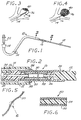
- FIGS 1 and 2 illustrate a preferred embodiment of an apparatus 10 for deploying an embolic device 12 in accordance with the present invention.
- the apparatus 10 comprises a microcatheter 14 having an axial lumen 15, and a deployment tube 16 that is insertable through the lumen 15 of the microcatheter 14.
- the microcatheter 14 is of conventional design, and many suitable microcatheters for the apparatus 10 are commercially available.
- the proximal end of the microcatheter 14 is provided with a fitting 18 for coupling to a source (not shown) of a fluid (such as saline solution), the flow of which is used to facilitate the passage of the deployment tube 16 through the microcatheter 14, as will be described below.
- a fluid such as saline solution
- the microcatheter 14, or at least its distal end, is preferably made of a radiopaque material, such as a biocompatible metal. Alternatively, it may be made of a suitable plastic, with a radiopaque insert (not shown) proximate its distal end, as is well known in the art.
- the deployment tube 16 is a long, thin, hollow, highly flexible tube, having an axial passage 20 and an overall length that is somewhat greater than that of the microcatheter 14.
- the deployment tube 16 has a proximal end to which is attached an inlet fitting 22 that communicates with the axial passage 20 and that is adapted for coupling to a liquid source (not shown).
- the source contains a biocompatible liquid that can be delivered to the inlet fitting 22 under pressure for purposes to be described below.
- the distal end of the deployment tube 16 is provided with a cup-like fitting 24 that serves as a holding element that is configured for frictional engagement with the proximal end of the embolic device 12.
- the interior of the holding element 24 communicates with the axial passage 20 of the deployment tube 16 by means of an axial bore 26.
- a substantial portion of the length of the deployment tube 16 extending proximally from the holding element 24 is formed as a highly flexible and compliant outer portion 28 formed from a continuous length of helically-coiled metal wire.
- the outer portion 28 concentrically surrounds an inner portion 30, formed from a highly-flexible polymeric material, the interior of which defines a distal portion of the axial passage 20 that is coupled to the axial bore 26 of the holding element 24.
- the proximal ends of both the outer portion 28 and the inner portion 30 are connected to the distal end of an internal transition fitting 32, the proximal end of which is connected to the distal end of a proximal tube section 34, which may be made of a flexible polymeric material.
- An axial bore 36 traverses the length of the transition fitting 32, providing fluid communication between the distal portion of the axial passage 20 that is within the inner portion 30, and the proximal portion of the axial passage 20 that is defined within the proximal tube section 34.
- the aforementioned inlet fitting 22 is connected to the proximal end of the proximal tube section 34.
- the embolic device 12 comprises a continuous, filamentous extrusion of polymeric "transition material".
- This transition material is initially in a soft, self-adherent, compliant state. While the material is in this state, the embolic device 12 is inserted into an aneurysm. The insertion results in a web-like mass of material that substantially fills the aneurysm and that substantially conforms to the interior shape of the aneurysm.
- any of several mechanisms is then employed controllably to transform the transition material into a rigid or semi-rigid state, in which the material forms a stable, thrombogenic "plug" inside the aneurysm.
- the embolic device 12 may be injected at a temperature slightly above body temperature and then cooled into its rigid or semi-rigid state by contact with the patient's vascular blood, or by the injection of a cooler saline solution.
- the polymeric material may be exposed to a hardening agent that reacts chemically or physically with the material to effect the transition to the rigid or semi-rigid state.
- the polymeric material may be mixed with a water-soluble, biocompatible plasticizer (as described below) that dissolves out in the vascular blood to leave a rigid or semi-rigid polymeric structure.
- the proximal end of the embolic device 12 Prior to deployment, and while the material of the embolic device 12 is in its initial soft, compliant state, the proximal end of the embolic device 12 is pushed into the holding element 24 of the deployment tube 16, where it is frictionally retained in place. With the distal end of the microcatheter 14 having previously been deployed adjacent the targeted aneurysm (designated by the numeral 36 in Figures 3 and 4), the distal end (not shown) of the embolic device 12 is then inserted into the fitting 18 at the proximal end of the microcatheter 14.
- a liquid such as a saline solution
- the flow of the liquid assists in carrying the embolic device 12 and the deployment tube 16 through the microcatheter 14 until the distal end of the deployment tube 16 is well within the aneurysm 36 ( Figure 3), at which point the embolic device 12 starts to form a web-like, thrombogenic mass or plug 40 within the aneurysm.
- the proximal end of the embolic device 12 is detached from the deployment tube 16 by the pressure of a fluid (such as saline solution) injected through the axial passage 20 of the deployment tube and the axial bore 26 of the holding element 24.
- the deployment tube 16 is withdrawn through the microcatheter 14 and reloaded with another embolic device 12, and the above-described deployment process is repeated as often as is needed to fill the aneurysm 36 completely ( Figure 4). As shown in Figure 4, the final embolic device 12 is then detached from the deployment tube 16 in the manner described above, and the deployment tube 16 is withdrawn from the microcatheter 14.
- the fluid used to carry the deployment tube 16 and the embolic device 12 through the microcatheter 14, and the fluid used to detach the embolic device 12 from the deployment tube are selected so that they do not effect the transition of the embolic device material from its soft state to its rigid or semi-rigid state.
- the transition material effects the transition by being cooled from slightly above body temperature (e.g., from about 40°C) to approximately normal body temperature (37°C)
- these deployment fluids are injected at about the higher temperature, so that the transition does not take place prematurely.
- the transition material of the embolic device(s) 12 installed within the aneurysm 36 can be transformed to its rigid or semi-rigid state by means of one of the aforementioned mechanisms, depending on the nature of the material itself.
- a "transition fluid" such as saline at the required temperature, can be injected through the microcatheter 14 to bathe the mass 40, thereby effecting the desired transition.
- FIGS 5 and 6 illustrate an embolic device 50 in accordance with a second preferred embodiment of the invention.
- the embolic device 50 comprises a hollow metal microcoil 52, the interior of which is filled with a core 54 of polymeric transition material.
- the embolic device 50 is rigidified by the transformation of the material of the core 54 from its soft, compliant state to its rigid or semi-rigid state effecting a temperature change, as described above.
- the deployment of the embolic device 50 is performed by essentially the same method as that used for the deployment of the previously-described embodiment.
- an embolic device 50' comprises a hollow metal microcoil 52', the distal end of which is closed by an end cap 56.
- the device 50' lacks a core. Instead, when the microcoil 52' is inserted into an aneurysm, but before it is detached from the deployment tube 16, a flowable transition material is injected into the interior of the microcoil 52' through the axial passage 20 of the deployment tube 16 and the axial bore 26 of the holding element 24. The injection of the transition material is illustrated in Figure 7 by the arrows designated by the numeral 58.
- the flexing and bending of the installed microcoil 52' causes interstices between the coils to open up, allowing the transition material to flow out of the microcoil, as indicated by the arrows designated by the numeral 60.
- the transition material then can be transformed into its rigid or semi-rigid state, thereby rigidifying the microcoil 52'.
- the exposed transition material that has flowed out of the interstices between the coils provides further rigidity and enhances the thrombogenicity of the device 50'.
- an embolic device 50 comprises a hollow metal microcoil 52" having an end cap 56" closing its distal end.
- the microcoil 52" has a plurality of apertures 62 along its length, only one of which is shown in the drawings.
- the apertures 62 provide additional paths for the outflow of the transition material, as shown by the arrows indicated by the numeral 64 in Figure 10.
- an embolic device 70 in accordance with this third embodiment is a chain-like structure comprising a plurality of interconnected metal links or segments 72, each of which has a socket 74 at one end and a slotted ball 76 at the other end.
- Each socket 74 is dimensioned to receive the ball 76 of the adjacent segment 72, the slotted configuration of the balls 76 allowing them to be slightly compressed to fit into the sockets 74.
- the balls 76 are loosely received in the sockets 74, and the segments 72 are dimensioned so that there is a gap between each adjacent pair.
- the entire chain-like structure of the device 70 can be flexibly deformed and twisted much like a microcoil to form the web-like mass 40 when deployed inside an aneurysm by means of the above-described method.
- an electric current is passed through it, resulting in the fusing of the balls 76 in the sockets 74 by electrolytic corrosion.
- the electric current can be applied through the deployment tube 16, provided that the deployment tube 16 (including the holding element 24) is made of a conductive metal with suitable electrodes (not shown) that connect the embolic device 70 to a current source (not shown).
- An embolic device 70' is a chain-like structure comprising a plurality of interconnected metal links or segments 72', each including a socket 74' at one end and a slotted ball 76' at the other end.
- the balls 76' are received in the sockets 74' as described above.
- the modification comprises an annular collar 78 around the socket 74' of each segment 72'.
- the collar 78 extends axially away from the ball 76' to abut against, or at least be closely adjacent to, the next adjacent segment 72'.
- the collar 78 is formed of a polymeric transition material that is initially in the soft, compliant state when the device 70' is inserted into an aneurysm, and that is transformed into its rigid or semi-rigid state, in the manner described above, when the aneurysm is filled. Since the collars 78, when rigidified, form interlinking elements between adjacent segments 72', the transformation of the material of the collars 78 rigidifies the entire device 70'. A similar effect can be achieved, at some cost savings, by the modified embolic device 70" of Figure 14, in which only alternating segments 72' are provided with the collar 78.
- FIGS 15 and 16 illustrate still another modification of the third preferred embodiment.
- an embolic device 70''' is a highly-compliant chain-like structure comprising a plurality of interconnected links or segments 72", each of which is hollow.
- Each of the segments 72" has a slotted, mushroom-shaped head portion 80, and a socket portion 82 that is shaped and dimensioned to receive the head portion 80 of an adjacent segment 72".
- the hollow segments 72" allow the embolic device 70''' to be inserted into an aneurysm over a guide wire (not shown), if desired.
- a transition material 84 (Fig.16) is injected, while in a flowable state, into the hollow interior of the device 70"', and the transformation of the device 70" from a soft compliant state into its rigid or semi-rigid state can be effected as described above.
- the segments 72" can be made of a metal and then fused together by electrolytic corrosion, as described above.
- transition materials which are used in accordance with the present invention to fill the aneurysm in a relatively soft, semi-rigid state as described above, and which thereafter harden to fill the aneurysm in a sufficiently rigid state
- the skilled artisan may refer to the self-hardening polymeric materials described in United States Patent No. 5,634,936.
- the materials described in this reference are polymers that, due to the judicious addition of cross-linking agents and/or cross-linking catalysts, are in a soft , compliant state while being introduced through a catheter, and harden only after they have been deposited in the aneurysm.
- Materials described in United States Patent No. 5,725,568 can also be selected for use in the present invention.
- a presently preferred material for use in the present invention constitutes a microcrystalline wax composition that is of the appropriate compliant consistency a few degrees above body temperature, but becomes sufficiently rigid when cooled to body temperature.
- waxes are, generally speaking, fatty acids having more than 12 carbon atoms and a straight alkyl chain.
- a microcrystalline wax material is readily formulated within the state-of-the-art to have the appropriate transition temperature.
- Another presently preferred material for use in the present invention is cellulose acetate polymer that is softened with ethyl lactate or dimethylsulfoxide (DMSO) plasticizer.
- Still other presently preferred materials are a class of polyurethane based copolymers that are available under the TECOPHILIC trademark from Thermedics Corporation. Specific commercial designations of these copolymers are HP-60D-60, SP-80A-150 and SP-93A-100.
- plasticizers that are selected primarily from DMSO, ethanol, and ethyl lactate, with DMSO being most suitable for HP-60D-60, and ethanol or ethyl lactate or mixtures thereof for SP-80A-150 and SP-93A-100.
- the above-noted plasticizers are sufficiently water soluble that after the intimate mixture of polymeric material and plasticizer has been deposited in the aneurysm, percolation of blood gradually washes out the plasticizer from the polymeric material to render it rigid.
- a composition that is well-suited for the transition material in the hollow microcoil embolic devices 50' and 50" of Figures 7 through 10, and for the transition material 84 of the embolic device 70''' of Figures 15 and 16, is cyanoacrylate.
- the cyanoacrylate rigidifies by polymerization when contacted by vascular blood which seeps into the embolic device 70''' between the segments 72".
- biocompatible polymers and copolymers such as ethylene vinyl alcohol copolymers, polycarbonate urethane copolymers, and hydrogels may be formulated with a sufficient amount of biocompatible plasticizer, such as DMSO, to render them semi-rigid and suitable for application in the present invention through the catheters described above. Thereafter, these materials harden sufficiently in the aneurysm due to the removal of the plasticizer by percolating blood.
- biocompatible plasticizer such as DMSO
Priority Applications (2)
| Application Number | Priority Date | Filing Date | Title |
|---|---|---|---|
| EP07104770A EP1806106B1 (en) | 1998-04-28 | 1999-04-23 | Apparatus for vascular embolization |
| EP04019762A EP1518502B1 (en) | 1998-04-28 | 1999-04-23 | Apparatus vascular embolization |
Applications Claiming Priority (3)
| Application Number | Priority Date | Filing Date | Title |
|---|---|---|---|
| US09/069,008 US6015424A (en) | 1998-04-28 | 1998-04-28 | Apparatus and method for vascular embolization |
| US69008 | 1998-04-28 | ||
| PCT/US1999/007399 WO1999055239A1 (en) | 1998-04-28 | 1999-04-23 | Apparatus and method for vascular embolization |
Related Child Applications (2)
| Application Number | Title | Priority Date | Filing Date |
|---|---|---|---|
| EP04019762A Division EP1518502B1 (en) | 1998-04-28 | 1999-04-23 | Apparatus vascular embolization |
| EP04019762.6 Division-Into | 2004-08-20 |
Publications (2)
| Publication Number | Publication Date |
|---|---|
| EP1073377A1 EP1073377A1 (en) | 2001-02-07 |
| EP1073377B1 true EP1073377B1 (en) | 2004-11-17 |
Family
ID=22086109
Family Applications (3)
| Application Number | Title | Priority Date | Filing Date |
|---|---|---|---|
| EP04019762A Expired - Lifetime EP1518502B1 (en) | 1998-04-28 | 1999-04-23 | Apparatus vascular embolization |
| EP07104770A Expired - Lifetime EP1806106B1 (en) | 1998-04-28 | 1999-04-23 | Apparatus for vascular embolization |
| EP99921377A Expired - Lifetime EP1073377B1 (en) | 1998-04-28 | 1999-04-23 | Apparatus for vascular embolization |
Family Applications Before (2)
| Application Number | Title | Priority Date | Filing Date |
|---|---|---|---|
| EP04019762A Expired - Lifetime EP1518502B1 (en) | 1998-04-28 | 1999-04-23 | Apparatus vascular embolization |
| EP07104770A Expired - Lifetime EP1806106B1 (en) | 1998-04-28 | 1999-04-23 | Apparatus for vascular embolization |
Country Status (11)
| Country | Link |
|---|---|
| US (2) | US6015424A (zh) |
| EP (3) | EP1518502B1 (zh) |
| JP (2) | JP4376458B2 (zh) |
| CN (1) | CN1200648C (zh) |
| AT (2) | ATE359031T1 (zh) |
| AU (4) | AU764797C (zh) |
| BR (1) | BR9910027A (zh) |
| CA (3) | CA2736639A1 (zh) |
| DE (2) | DE69921979T2 (zh) |
| ES (3) | ES2232136T3 (zh) |
| WO (1) | WO1999055239A1 (zh) |
Cited By (2)
| Publication number | Priority date | Publication date | Assignee | Title |
|---|---|---|---|---|
| US8932317B2 (en) | 1999-06-02 | 2015-01-13 | Microvention, Inc. | Intracorporeal occlusive device and method |
| US9561125B2 (en) | 2010-04-14 | 2017-02-07 | Microvention, Inc. | Implant delivery device |
Families Citing this family (207)
| Publication number | Priority date | Publication date | Assignee | Title |
|---|---|---|---|---|
| US5871537A (en) * | 1996-02-13 | 1999-02-16 | Scimed Life Systems, Inc. | Endovascular apparatus |
| US6146373A (en) * | 1997-10-17 | 2000-11-14 | Micro Therapeutics, Inc. | Catheter system and method for injection of a liquid embolic composition and a solidification agent |
| US6511468B1 (en) * | 1997-10-17 | 2003-01-28 | Micro Therapeutics, Inc. | Device and method for controlling injection of liquid embolic composition |
| US7070607B2 (en) * | 1998-01-27 | 2006-07-04 | The Regents Of The University Of California | Bioabsorbable polymeric implants and a method of using the same to create occlusions |
| US6113629A (en) * | 1998-05-01 | 2000-09-05 | Micrus Corporation | Hydrogel for the therapeutic treatment of aneurysms |
| DK173411B2 (da) * | 1998-06-19 | 2007-04-16 | Coloplast As | Opsamlingspose til menneskelige legemssekreter |
| US6051607A (en) * | 1998-07-02 | 2000-04-18 | Micro Therapeutics, Inc. | Vascular embolizing compositions comprising ethyl lactate and methods for their use |
| US6165193A (en) * | 1998-07-06 | 2000-12-26 | Microvention, Inc. | Vascular embolization with an expansible implant |
| US7410482B2 (en) * | 1998-09-04 | 2008-08-12 | Boston Scientific-Scimed, Inc. | Detachable aneurysm neck bridge |
| CA2323151C (en) * | 1999-01-27 | 2007-04-10 | Regents Of The University Of California | Biodegradable polymer/protein based coils for intralumenal implants |
| US7018401B1 (en) | 1999-02-01 | 2006-03-28 | Board Of Regents, The University Of Texas System | Woven intravascular devices and methods for making the same and apparatus for delivery of the same |
| US6312421B1 (en) | 1999-07-23 | 2001-11-06 | Neurovasx, Inc. | Aneurysm embolization material and device |
| US6602261B2 (en) | 1999-10-04 | 2003-08-05 | Microvention, Inc. | Filamentous embolic device with expansile elements |
| US6544225B1 (en) * | 2000-02-29 | 2003-04-08 | Cordis Neurovascular, Inc. | Embolic coil hydraulic deployment system with purge mechanism |
| US6514264B1 (en) * | 2000-06-01 | 2003-02-04 | Cordis Neurovascular, Inc. | Embolic coil hydraulic deployment system with purge mechanism |
| US6530934B1 (en) * | 2000-06-06 | 2003-03-11 | Sarcos Lc | Embolic device composed of a linear sequence of miniature beads |
| US6355275B1 (en) | 2000-06-23 | 2002-03-12 | Carbon Medical Technologies, Inc. | Embolization using carbon coated microparticles |
| EP1169969A1 (en) * | 2000-07-05 | 2002-01-09 | Medtronic Ave, Inc. | Pedicle occlusion device |
| KR100387384B1 (ko) * | 2000-07-26 | 2003-06-12 | 규 호 이 | 색전 물질 분리 검출 시스템 및 그의 방법과 색전술용어셈블리 |
| US6855154B2 (en) | 2000-08-11 | 2005-02-15 | University Of Louisville Research Foundation, Inc. | Endovascular aneurysm treatment device and method |
| US6394965B1 (en) | 2000-08-15 | 2002-05-28 | Carbon Medical Technologies, Inc. | Tissue marking using biocompatible microparticles |
| US20040266983A1 (en) * | 2000-08-17 | 2004-12-30 | Reeve Lorraine E | Purified polyoxyalkylene block copolymers |
| US8313504B2 (en) | 2000-09-18 | 2012-11-20 | Cordis Corporation | Foam matrix embolization device |
| US6723108B1 (en) * | 2000-09-18 | 2004-04-20 | Cordis Neurovascular, Inc | Foam matrix embolization device |
| US6605101B1 (en) | 2000-09-26 | 2003-08-12 | Microvention, Inc. | Microcoil vaso-occlusive device with multi-axis secondary configuration |
| US7029486B2 (en) * | 2000-09-26 | 2006-04-18 | Microvention, Inc. | Microcoil vaso-occlusive device with multi-axis secondary configuration |
| US7033374B2 (en) * | 2000-09-26 | 2006-04-25 | Microvention, Inc. | Microcoil vaso-occlusive device with multi-axis secondary configuration |
| US6689141B2 (en) | 2000-10-18 | 2004-02-10 | Microvention, Inc. | Mechanism for the deployment of endovascular implants |
| US20040204701A1 (en) * | 2000-10-18 | 2004-10-14 | Brian Cox | Mechanism for the deployment of endovascular implants |
| US6607538B1 (en) | 2000-10-18 | 2003-08-19 | Microvention, Inc. | Mechanism for the deployment of endovascular implants |
| US6602269B2 (en) | 2001-03-30 | 2003-08-05 | Scimed Life Systems | Embolic devices capable of in-situ reinforcement |
| US20020165582A1 (en) * | 2001-04-26 | 2002-11-07 | Porter Christopher H. | Method and apparatus for delivering materials to the body |
| EP1392182A1 (en) * | 2001-05-04 | 2004-03-03 | Concentric Medical | Hydrogel vaso-occlusive device |
| AU2002340749A1 (en) * | 2001-05-04 | 2002-11-18 | Concentric Medical | Coated combination vaso-occlusive device |
| WO2002089676A2 (en) * | 2001-05-04 | 2002-11-14 | Concentric Medical | Hydrogel filament vaso-occlusive device |
| US6607539B1 (en) * | 2001-05-18 | 2003-08-19 | Endovascular Technologies, Inc. | Electric endovascular implant depolyment system |
| ATE516759T1 (de) | 2001-05-29 | 2011-08-15 | Microvention Inc | Verfahren zur herstellung von expandierbaren filamentösen embolisierungsvorrichtungen |
| US7687053B2 (en) * | 2001-08-20 | 2010-03-30 | Boston Scientific Scimed, Inc. | Embolic compositions with non-cyanoacrylate rheology modifying agents |
| US20030050635A1 (en) * | 2001-08-22 | 2003-03-13 | Csaba Truckai | Embolization systems and techniques for treating tumors |
| US20030093111A1 (en) * | 2001-10-26 | 2003-05-15 | Concentric Medical | Device for vaso-occlusion and interventional therapy |
| WO2003039376A1 (en) | 2001-11-07 | 2003-05-15 | Microvention, Inc. | Microcoil vaso-occlusive device with multi-axis secondary configuration |
| US20060292206A1 (en) | 2001-11-26 | 2006-12-28 | Kim Steven W | Devices and methods for treatment of vascular aneurysms |
| US20030199887A1 (en) * | 2002-04-23 | 2003-10-23 | David Ferrera | Filamentous embolization device and method of use |
| US7048719B1 (en) | 2002-06-07 | 2006-05-23 | Microvention, Inc. | Endovascular catheter resheathing apparatus and related methods |
| US8425549B2 (en) | 2002-07-23 | 2013-04-23 | Reverse Medical Corporation | Systems and methods for removing obstructive matter from body lumens and treating vascular defects |
| US20050171572A1 (en) | 2002-07-31 | 2005-08-04 | Microvention, Inc. | Multi-layer coaxial vaso-occlusive device |
| US8273100B2 (en) * | 2002-07-31 | 2012-09-25 | Microvention, Inc. | Three element coaxial vaso-occlusive device |
| US7481821B2 (en) | 2002-11-12 | 2009-01-27 | Thomas J. Fogarty | Embolization device and a method of using the same |
| US20040115164A1 (en) * | 2002-12-17 | 2004-06-17 | Pierce Ryan K. | Soft filament occlusive device delivery system |
| US20050043585A1 (en) * | 2003-01-03 | 2005-02-24 | Arindam Datta | Reticulated elastomeric matrices, their manufacture and use in implantable devices |
| US7229454B2 (en) * | 2003-01-07 | 2007-06-12 | Boston Scientific Scimed, Inc. | Occlusive cinching devices and methods of use |
| US20040260382A1 (en) | 2003-02-12 | 2004-12-23 | Fogarty Thomas J. | Intravascular implants and methods of using the same |
| US7367989B2 (en) * | 2003-02-27 | 2008-05-06 | Scimed Life Systems, Inc. | Rotating balloon expandable sheath bifurcation delivery |
| US7314480B2 (en) * | 2003-02-27 | 2008-01-01 | Boston Scientific Scimed, Inc. | Rotating balloon expandable sheath bifurcation delivery |
| JP4909071B2 (ja) * | 2003-03-24 | 2012-04-04 | プルーローメッド, インコーポレイテッド | 逆感熱性ポリマーを使用する一時的な塞栓形成 |
| ES2660627T3 (es) | 2003-05-15 | 2018-03-23 | Biomerix Corporation | Matrices elastoméricas reticuladas, su fabricación y su utilización en dispositivos implantables |
| CN100400002C (zh) | 2003-07-03 | 2008-07-09 | 库克公司 | 用于堵塞流过体内管路的流体的封堵器 |
| US20050015110A1 (en) * | 2003-07-18 | 2005-01-20 | Fogarty Thomas J. | Embolization device and a method of using the same |
| US20050119687A1 (en) * | 2003-09-08 | 2005-06-02 | Dacey Ralph G.Jr. | Methods of, and materials for, treating vascular defects with magnetically controllable hydrogels |
| US7645292B2 (en) * | 2003-10-27 | 2010-01-12 | Boston Scientific Scimed, Inc. | Vaso-occlusive devices with in-situ stiffening elements |
| US20050090856A1 (en) * | 2003-10-27 | 2005-04-28 | Scimed Life Systems, Inc. | Vasco-occlusive devices with bioactive elements |
| EP1689482A1 (en) * | 2003-10-28 | 2006-08-16 | Peacock, James C., III | Embolic filter device and related systems and methods |
| WO2005046438A2 (en) * | 2003-11-06 | 2005-05-26 | Pluromed, Inc. | Internal clamp for surgical procedures |
| US7070641B1 (en) | 2003-12-03 | 2006-07-04 | Fleetguard, Inc. | Carbon media filter element |
| US20070104752A1 (en) * | 2003-12-10 | 2007-05-10 | Lee Jeffrey A | Aneurysm embolization material and device |
| US20080109057A1 (en) * | 2003-12-10 | 2008-05-08 | Calabria Marie F | Multiple point detacher system |
| US20050149108A1 (en) * | 2003-12-17 | 2005-07-07 | Microvention, Inc. | Implant delivery and detachment system and method |
| US7294123B2 (en) * | 2003-12-17 | 2007-11-13 | Corris Neurovascular, Inc. | Activatable bioactive vascular occlusive device and method of use |
| US7763077B2 (en) | 2003-12-24 | 2010-07-27 | Biomerix Corporation | Repair of spinal annular defects and annulo-nucleoplasty regeneration |
| US7686841B2 (en) * | 2003-12-29 | 2010-03-30 | Boston Scientific Scimed, Inc. | Rotating balloon expandable sheath bifurcation delivery system |
| US7922753B2 (en) * | 2004-01-13 | 2011-04-12 | Boston Scientific Scimed, Inc. | Bifurcated stent delivery system |
| US20050165480A1 (en) * | 2004-01-23 | 2005-07-28 | Maybelle Jordan | Endovascular treatment devices and methods |
| US8192676B2 (en) * | 2004-02-12 | 2012-06-05 | Valspar Sourcing, Inc. | Container having barrier properties and method of manufacturing the same |
| US8012192B2 (en) | 2004-02-18 | 2011-09-06 | Boston Scientific Scimed, Inc. | Multi-stent delivery system |
| US20070190108A1 (en) * | 2004-05-17 | 2007-08-16 | Arindam Datta | High performance reticulated elastomeric matrix preparation, properties, reinforcement, and use in surgical devices, tissue augmentation and/or tissue repair |
| US20050267510A1 (en) * | 2004-05-26 | 2005-12-01 | Nasser Razack | Device for the endovascular treatment of intracranial aneurysms |
| US20050273149A1 (en) * | 2004-06-08 | 2005-12-08 | Tran Thomas T | Bifurcated stent delivery system |
| RU2383558C2 (ru) * | 2004-07-08 | 2010-03-10 | Рева Медикал, Инк. | Полимеры с кристаллизующимися боковыми цепями для медицинского применения |
| US8703113B2 (en) * | 2004-07-08 | 2014-04-22 | Reva Medical Inc. | Side-chain crystallizable polymers for medical applications |
| CN101014642B (zh) * | 2004-08-13 | 2010-04-21 | 雷瓦医药公司 | 用于多种应用的固有不透射线的可生物再吸收的聚合物 |
| US20060047299A1 (en) * | 2004-08-24 | 2006-03-02 | Ferguson Patrick J | Vascular occlusive wire with extruded bioabsorbable sheath |
| EP1793744B1 (de) | 2004-09-22 | 2008-12-17 | Dendron GmbH | Medizinisches implantat |
| DE502004010411D1 (de) | 2004-09-22 | 2009-12-31 | Dendron Gmbh | Vorrichtung zur implantation von mikrowendeln |
| WO2006042114A1 (en) * | 2004-10-06 | 2006-04-20 | Cook, Inc. | Emboli capturing device having a coil and method for capturing emboli |
| US7201918B2 (en) * | 2004-11-16 | 2007-04-10 | Microvention, Inc. | Compositions, systems and methods for treatment of defects in blood vessels |
| US7413588B2 (en) * | 2004-11-24 | 2008-08-19 | Fleetguard, Inc. | High efficiency, low restriction, cost effective filter |
| US20060116713A1 (en) * | 2004-11-26 | 2006-06-01 | Ivan Sepetka | Aneurysm treatment devices and methods |
| US8771294B2 (en) | 2004-11-26 | 2014-07-08 | Biomerix Corporation | Aneurysm treatment devices and methods |
| US20060116714A1 (en) * | 2004-11-26 | 2006-06-01 | Ivan Sepetka | Coupling and release devices and methods for their assembly and use |
| US8945169B2 (en) | 2005-03-15 | 2015-02-03 | Cook Medical Technologies Llc | Embolic protection device |
| US8221446B2 (en) | 2005-03-15 | 2012-07-17 | Cook Medical Technologies | Embolic protection device |
| US20060259132A1 (en) * | 2005-05-02 | 2006-11-16 | Cook Incorporated | Vascular stent for embolic protection |
| US8109962B2 (en) | 2005-06-20 | 2012-02-07 | Cook Medical Technologies Llc | Retrievable device having a reticulation portion with staggered struts |
| US7850708B2 (en) * | 2005-06-20 | 2010-12-14 | Cook Incorporated | Embolic protection device having a reticulated body with staggered struts |
| US20070001346A1 (en) * | 2005-06-30 | 2007-01-04 | Murty Vyakarnam | Active embolization device |
| US7780695B2 (en) * | 2005-06-30 | 2010-08-24 | Codman & Shurtleff, Inc. | Chemically based vascular occlusion device deployment |
| US7766934B2 (en) * | 2005-07-12 | 2010-08-03 | Cook Incorporated | Embolic protection device with an integral basket and bag |
| US7771452B2 (en) | 2005-07-12 | 2010-08-10 | Cook Incorporated | Embolic protection device with a filter bag that disengages from a basket |
| US8187298B2 (en) * | 2005-08-04 | 2012-05-29 | Cook Medical Technologies Llc | Embolic protection device having inflatable frame |
| US8377092B2 (en) | 2005-09-16 | 2013-02-19 | Cook Medical Technologies Llc | Embolic protection device |
| US8632562B2 (en) * | 2005-10-03 | 2014-01-21 | Cook Medical Technologies Llc | Embolic protection device |
| US8182508B2 (en) * | 2005-10-04 | 2012-05-22 | Cook Medical Technologies Llc | Embolic protection device |
| US8252017B2 (en) * | 2005-10-18 | 2012-08-28 | Cook Medical Technologies Llc | Invertible filter for embolic protection |
| KR101334502B1 (ko) | 2005-10-19 | 2013-12-05 | 펄사 배스큘러, 아이엔씨. | 내강과 조직 결함을 치료하고 혈관내 결찰을 위한 장치 및 시스템 |
| CN103381101B (zh) * | 2005-10-19 | 2017-12-01 | 帕尔萨脉管公司 | 用于脉管内夹持并修补内腔和组织缺陷的方法和系统 |
| US8216269B2 (en) | 2005-11-02 | 2012-07-10 | Cook Medical Technologies Llc | Embolic protection device having reduced profile |
| US20070100372A1 (en) * | 2005-11-02 | 2007-05-03 | Cook Incorporated | Embolic protection device having a filter |
| US8152831B2 (en) * | 2005-11-17 | 2012-04-10 | Cook Medical Technologies Llc | Foam embolic protection device |
| US20070225680A1 (en) * | 2006-03-21 | 2007-09-27 | Medtronic Vascular, Inc. | Guiding catheter with chemically softened distal portion and method of making same |
| EP2015683B1 (en) * | 2006-04-17 | 2015-12-09 | Covidien LP | System for mechanically positioning intravascular implants |
| US8777979B2 (en) | 2006-04-17 | 2014-07-15 | Covidien Lp | System and method for mechanically positioning intravascular implants |
| KR101443926B1 (ko) | 2006-06-15 | 2014-10-02 | 마이크로벤션, 인코포레이티드 | 팽창성 중합체로 제조된 색전술용 장치 |
| US20080071307A1 (en) * | 2006-09-19 | 2008-03-20 | Cook Incorporated | Apparatus and methods for in situ embolic protection |
| WO2008042266A2 (en) * | 2006-09-28 | 2008-04-10 | Cook Incorporated | Thoracic aortic aneurysm repair apparatus and method |
| CN101541355B (zh) | 2006-10-17 | 2012-08-08 | 雷瓦医药公司 | N-取代的单体和聚合物 |
| KR101297043B1 (ko) | 2006-10-22 | 2013-08-14 | 이데브 테크놀로지스, 아이엔씨. | 스트랜드 단부를 고정하기 위한 방법 및 이의 장치 |
| EP2083767B1 (en) | 2006-10-22 | 2019-04-03 | IDEV Technologies, INC. | Devices for stent advancement |
| US20080114402A1 (en) * | 2006-11-10 | 2008-05-15 | Warsaw Orthopedic, Inc. | Devices and Methods for Correcting a Spinal Deformity |
| WO2008074027A1 (en) * | 2006-12-13 | 2008-06-19 | Biomerix Corporation | Aneurysm occlusion devices |
| US9901434B2 (en) | 2007-02-27 | 2018-02-27 | Cook Medical Technologies Llc | Embolic protection device including a Z-stent waist band |
| US8257719B2 (en) * | 2007-03-06 | 2012-09-04 | Ranir, Llc | Oral care layer and related method of manufacture |
| JP5227344B2 (ja) | 2007-03-13 | 2013-07-03 | タイコ ヘルスケア グループ リミテッド パートナーシップ | インプラント、マンドレル、およびインプラント形成方法 |
| JP5249249B2 (ja) * | 2007-03-13 | 2013-07-31 | コヴィディエン リミテッド パートナーシップ | コイルと耐伸張性部材とが含まれているインプラント |
| JP5120058B2 (ja) | 2007-05-23 | 2013-01-16 | 日本精工株式会社 | 転がり軸受ユニットの状態量測定装置及びその製造方法 |
| EP2162101B1 (en) * | 2007-06-25 | 2019-02-20 | MicroVention, Inc. | Self-expanding prosthesis |
| US9138307B2 (en) | 2007-09-14 | 2015-09-22 | Cook Medical Technologies Llc | Expandable device for treatment of a stricture in a body vessel |
| US8419748B2 (en) * | 2007-09-14 | 2013-04-16 | Cook Medical Technologies Llc | Helical thrombus removal device |
| US8252018B2 (en) * | 2007-09-14 | 2012-08-28 | Cook Medical Technologies Llc | Helical embolic protection device |
| US8088140B2 (en) | 2008-05-19 | 2012-01-03 | Mindframe, Inc. | Blood flow restorative and embolus removal methods |
| US9220522B2 (en) * | 2007-10-17 | 2015-12-29 | Covidien Lp | Embolus removal systems with baskets |
| US8926680B2 (en) * | 2007-11-12 | 2015-01-06 | Covidien Lp | Aneurysm neck bridging processes with revascularization systems methods and products thereby |
| US8585713B2 (en) | 2007-10-17 | 2013-11-19 | Covidien Lp | Expandable tip assembly for thrombus management |
| US20100174309A1 (en) * | 2008-05-19 | 2010-07-08 | Mindframe, Inc. | Recanalization/revascularization and embolus addressing systems including expandable tip neuro-microcatheter |
| US20100256600A1 (en) * | 2009-04-04 | 2010-10-07 | Ferrera David A | Neurovascular otw pta balloon catheter and delivery system |
| US8066757B2 (en) * | 2007-10-17 | 2011-11-29 | Mindframe, Inc. | Blood flow restoration and thrombus management methods |
| US10123803B2 (en) | 2007-10-17 | 2018-11-13 | Covidien Lp | Methods of managing neurovascular obstructions |
| US9198687B2 (en) * | 2007-10-17 | 2015-12-01 | Covidien Lp | Acute stroke revascularization/recanalization systems processes and products thereby |
| US11337714B2 (en) | 2007-10-17 | 2022-05-24 | Covidien Lp | Restoring blood flow and clot removal during acute ischemic stroke |
| US20090137981A1 (en) * | 2007-11-26 | 2009-05-28 | Valor Medical | Methods of treating a blood vessel |
| WO2009086208A2 (en) | 2007-12-21 | 2009-07-09 | Microvention, Inc. | Hydrogel filaments for biomedical uses |
| CN102036619B (zh) | 2007-12-21 | 2014-07-23 | 微排放器公司 | 检测植入物的脱卸的系统 |
| CN102065779B (zh) | 2007-12-21 | 2014-02-12 | 微排放器公司 | 用于定位可脱卸植入物的脱卸区域的系统和方法 |
| US8940003B2 (en) | 2008-02-22 | 2015-01-27 | Covidien Lp | Methods and apparatus for flow restoration |
| US20090227976A1 (en) * | 2008-03-05 | 2009-09-10 | Calabria Marie F | Multiple biocompatible polymeric strand aneurysm embolization system and method |
| EP2271390A4 (en) * | 2008-04-11 | 2016-07-20 | Covidien Lp | MONORAIL NEURO MICRO CATHETER FOR DISTRIBUTING MEDICAL DEVICES FOR THE TREATMENT OF STROKE, PROCESSES AND PRODUCTS |
| US20090318948A1 (en) * | 2008-04-22 | 2009-12-24 | Coherex Medical, Inc. | Device, system and method for aneurysm embolization |
| US10716573B2 (en) | 2008-05-01 | 2020-07-21 | Aneuclose | Janjua aneurysm net with a resilient neck-bridging portion for occluding a cerebral aneurysm |
| US10028747B2 (en) | 2008-05-01 | 2018-07-24 | Aneuclose Llc | Coils with a series of proximally-and-distally-connected loops for occluding a cerebral aneurysm |
| EP2444116B1 (en) | 2008-08-19 | 2016-01-06 | Covidien LP | Detachable tip microcatheter |
| US8133199B2 (en) | 2008-08-27 | 2012-03-13 | Boston Scientific Scimed, Inc. | Electroactive polymer activation system for a medical device |
| KR20110102422A (ko) * | 2008-12-10 | 2011-09-16 | 마이크로벤션, 인코포레이티드 | 미세카테터 |
| US8388644B2 (en) | 2008-12-29 | 2013-03-05 | Cook Medical Technologies Llc | Embolic protection device and method of use |
| US20100211094A1 (en) * | 2009-02-18 | 2010-08-19 | Cook Incorporated | Umbrella distal embolic protection device |
| WO2010117883A1 (en) * | 2009-04-06 | 2010-10-14 | Boston Scientific Scimed, Inc. | Delivery wire for occlusive device delivery system |
| US20100274277A1 (en) * | 2009-04-27 | 2010-10-28 | Cook Incorporated | Embolic protection device with maximized flow-through |
| US10639396B2 (en) | 2015-06-11 | 2020-05-05 | Microvention, Inc. | Polymers |
| JP5472595B2 (ja) * | 2009-08-26 | 2014-04-16 | セイコーエプソン株式会社 | 液体噴射ヘッド及び液体噴射装置 |
| EP2480166B1 (en) * | 2009-09-24 | 2017-11-29 | Microvention, Inc. | Injectable hydrogel filaments for biomedical uses |
| US8434489B2 (en) * | 2009-10-23 | 2013-05-07 | Conceptus, Inc. | Contraceptive devices and methods |
| BR112012009287A2 (pt) * | 2009-10-26 | 2017-06-06 | Microvention Inc | dispositivo de embolização feito de polímero expansível |
| US9358140B1 (en) | 2009-11-18 | 2016-06-07 | Aneuclose Llc | Stent with outer member to embolize an aneurysm |
| US9023095B2 (en) | 2010-05-27 | 2015-05-05 | Idev Technologies, Inc. | Stent delivery system with pusher assembly |
| US9192746B2 (en) * | 2010-06-07 | 2015-11-24 | Cook Medical Technologies Llc | Reperfusion catheter system |
| JP6066931B2 (ja) | 2011-02-25 | 2017-01-25 | マイクロベンション インコーポレイテッド | 補強されたバルーンカテーテル |
| US10028745B2 (en) | 2011-03-30 | 2018-07-24 | Noha, Llc | Advanced endovascular clip and method of using same |
| US10398444B2 (en) | 2011-03-30 | 2019-09-03 | Noha, Llc | Advanced endovascular clip and method of using same |
| WO2012145431A2 (en) | 2011-04-18 | 2012-10-26 | Microvention, Inc. | Embolic devices |
| KR102018035B1 (ko) | 2011-06-03 | 2019-09-05 | 펄사 배스큘라, 아이엔씨. | 추가적인 고정 메커니즘을 가진 동맥류 장치 및 이와 관련된 시스템과 방법 |
| WO2013049837A1 (en) | 2011-09-30 | 2013-04-04 | Medicalcue, Inc. | Umbilical probe measurement systems |
| US9119625B2 (en) | 2011-10-05 | 2015-09-01 | Pulsar Vascular, Inc. | Devices, systems and methods for enclosing an anatomical opening |
| US9579104B2 (en) | 2011-11-30 | 2017-02-28 | Covidien Lp | Positioning and detaching implants |
| KR101315443B1 (ko) | 2011-12-02 | 2013-10-07 | 강호창 | 마이크로코일 어셈블리 |
| US9011480B2 (en) | 2012-01-20 | 2015-04-21 | Covidien Lp | Aneurysm treatment coils |
| US9687245B2 (en) | 2012-03-23 | 2017-06-27 | Covidien Lp | Occlusive devices and methods of use |
| WO2013158781A1 (en) | 2012-04-18 | 2013-10-24 | Microvention, Inc. | Embolic devices |
| SG11201406845YA (en) | 2012-04-24 | 2014-11-27 | Urogyn B V | Bulking agent applicator for treating female urinary incontinence |
| EP2656822B1 (en) * | 2012-04-24 | 2014-12-03 | Urogyn B.V. | Applicator for delivering an occluding compound in a fallopian tube |
| WO2013166475A1 (en) | 2012-05-04 | 2013-11-07 | Interventco Llc | Device and method for filling of aneurysm or body cavity |
| US10124087B2 (en) | 2012-06-19 | 2018-11-13 | Covidien Lp | Detachable coupling for catheter |
| CA2904862A1 (en) | 2013-03-14 | 2014-10-02 | Incumedx Inc. | Implants, methods of manufacturing the same, and devices and methods for delivering the implants to a vascular disorder of a patient |
| EP3068337B1 (en) | 2013-11-13 | 2022-10-05 | Covidien LP | Galvanically assisted attachment of medical devices to thrombus |
| US10398441B2 (en) | 2013-12-20 | 2019-09-03 | Terumo Corporation | Vascular occlusion |
| US11224437B2 (en) | 2014-01-14 | 2022-01-18 | Penumbra, Inc. | Soft embolic implant |
| US10124090B2 (en) | 2014-04-03 | 2018-11-13 | Terumo Corporation | Embolic devices |
| US9713475B2 (en) | 2014-04-18 | 2017-07-25 | Covidien Lp | Embolic medical devices |
| CN106456836B (zh) | 2014-04-29 | 2019-12-06 | 微仙美国有限公司 | 包含活性剂的聚合物 |
| US10092663B2 (en) | 2014-04-29 | 2018-10-09 | Terumo Corporation | Polymers |
| US20150327868A1 (en) * | 2014-05-13 | 2015-11-19 | Ndi Tip Teknolojileri Anonim Sirketi | Retractable and rapid disconnect, floating diameter embolic coil product and delivery system |
| WO2016039979A2 (en) | 2014-09-08 | 2016-03-17 | Stryker Corporation | Vaso-occlusive devices with in-situ stiffening |
| CN107249483B (zh) * | 2014-09-15 | 2020-04-28 | 恩波医疗有限公司 | 栓塞装置 |
| US10857012B2 (en) | 2015-01-20 | 2020-12-08 | Neurogami Medical, Inc. | Vascular implant |
| US10736730B2 (en) | 2015-01-20 | 2020-08-11 | Neurogami Medical, Inc. | Vascular implant |
| US11484319B2 (en) | 2015-01-20 | 2022-11-01 | Neurogami Medical, Inc. | Delivery system for micrograft for treating intracranial aneurysms |
| CA2972620C (en) | 2015-01-20 | 2023-08-01 | Neurogami Medical, Inc. | Micrograft for the treatment of intracranial aneurysms and method for use |
| US10925611B2 (en) | 2015-01-20 | 2021-02-23 | Neurogami Medical, Inc. | Packaging for surgical implant |
| US10265515B2 (en) | 2015-03-27 | 2019-04-23 | Covidien Lp | Galvanically assisted aneurysm treatment |
| US10307168B2 (en) | 2015-08-07 | 2019-06-04 | Terumo Corporation | Complex coil and manufacturing techniques |
| WO2017053784A1 (en) | 2015-09-25 | 2017-03-30 | Covidien Lp | Medical device delivery system |
| US10052108B2 (en) | 2015-10-30 | 2018-08-21 | Incumedx, Inc. | Devices and methods for delivering an implant to a vascular disorder |
| US11090055B2 (en) | 2015-10-30 | 2021-08-17 | Incumedx Inc. | Devices and methods for delivering an implant to a vascular disorder |
| US10420563B2 (en) | 2016-07-08 | 2019-09-24 | Neurogami Medical, Inc. | Delivery system insertable through body lumen |
| JP6869533B2 (ja) * | 2017-03-09 | 2021-05-12 | 国立大学法人大阪大学 | 多節環状弾性体 |
| US11129621B2 (en) * | 2018-12-17 | 2021-09-28 | Covidien Lp | Devices, systems, and methods for the treatment of vascular defects |
| KR102316501B1 (ko) * | 2019-07-17 | 2021-10-22 | 한스바이오메드 주식회사 | 색전 코일용 앵커 및 이를 포함하는 색전 코일 |
| CN113546234B (zh) * | 2020-04-24 | 2022-09-20 | 苏州医本生命科技有限公司 | 一种血管介入具有示踪功能的药物制剂及其输送系统 |
| KR20220046162A (ko) | 2020-10-07 | 2022-04-14 | 주식회사 엘지생활건강 | 울릉산마늘 추출물을 포함하는 피부 상태 개선용 조성물 |
| CN116761559A (zh) * | 2020-11-19 | 2023-09-15 | 波士顿科学国际有限公司 | 用于涂层线圈的装置、系统和方法 |
Family Cites Families (41)
| Publication number | Priority date | Publication date | Assignee | Title |
|---|---|---|---|---|
| HU184722B (en) * | 1980-02-18 | 1984-10-29 | Laszlo Lazar | Therapeutically suitable silicone rubber mixture and therapeuticaid |
| US4795741A (en) * | 1987-05-06 | 1989-01-03 | Biomatrix, Inc. | Compositions for therapeutic percutaneous embolization and the use thereof |
| US4819637A (en) * | 1987-09-01 | 1989-04-11 | Interventional Therapeutics Corporation | System for artificial vessel embolization and devices for use therewith |
| US4994069A (en) * | 1988-11-02 | 1991-02-19 | Target Therapeutics | Vaso-occlusion coil and method |
| US5163952A (en) * | 1990-09-14 | 1992-11-17 | Michael Froix | Expandable polymeric stent with memory and delivery apparatus and method |
| US5167624A (en) * | 1990-11-09 | 1992-12-01 | Catheter Research, Inc. | Embolus delivery system and method |
| US5133731A (en) * | 1990-11-09 | 1992-07-28 | Catheter Research, Inc. | Embolus supply system and method |
| US5226911A (en) * | 1991-10-02 | 1993-07-13 | Target Therapeutics | Vasoocclusion coil with attached fibrous element(s) |
| JP3356447B2 (ja) * | 1991-10-16 | 2002-12-16 | テルモ株式会社 | 乾燥高分子ゲルからなる血管病変塞栓材料 |
| US5443478A (en) * | 1992-09-02 | 1995-08-22 | Board Of Regents, The University Of Texas System | Multi-element intravascular occlusion device |
| US5469867A (en) * | 1992-09-02 | 1995-11-28 | Landec Corporation | Cast-in place thermoplastic channel occluder |
| US5312415A (en) * | 1992-09-22 | 1994-05-17 | Target Therapeutics, Inc. | Assembly for placement of embolic coils using frictional placement |
| EP0617633B1 (en) * | 1992-09-22 | 1999-12-01 | Target Therapeutics | Detachable embolic coil assembly |
| US5350397A (en) * | 1992-11-13 | 1994-09-27 | Target Therapeutics, Inc. | Axially detachable embolic coil assembly |
| US5382259A (en) * | 1992-10-26 | 1995-01-17 | Target Therapeutics, Inc. | Vasoocclusion coil with attached tubular woven or braided fibrous covering |
| US5382260A (en) * | 1992-10-30 | 1995-01-17 | Interventional Therapeutics Corp. | Embolization device and apparatus including an introducer cartridge and method for delivering the same |
| US5690666A (en) * | 1992-11-18 | 1997-11-25 | Target Therapeutics, Inc. | Ultrasoft embolism coils and process for using them |
| US5443454A (en) * | 1992-12-09 | 1995-08-22 | Terumo Kabushiki Kaisha | Catheter for embolectomy |
| ES2123135T3 (es) * | 1993-03-23 | 1999-01-01 | Focal Inc | Aparato y metodo para la aplicacion local de material polimerico a tejido. |
| JP2535785B2 (ja) * | 1994-06-03 | 1996-09-18 | 工業技術院長 | 血管塞栓剤 |
| ES2340142T3 (es) * | 1994-07-08 | 2010-05-31 | Ev3 Inc. | Sistema para llevar a cabo un procedimiento intravascular. |
| US5690671A (en) | 1994-12-13 | 1997-11-25 | Micro Interventional Systems, Inc. | Embolic elements and methods and apparatus for their delivery |
| US5814062A (en) * | 1994-12-22 | 1998-09-29 | Target Therapeutics, Inc. | Implant delivery assembly with expandable coupling/decoupling mechanism |
| US5578074A (en) * | 1994-12-22 | 1996-11-26 | Target Therapeutics, Inc. | Implant delivery method and assembly |
| US5634936A (en) * | 1995-02-06 | 1997-06-03 | Scimed Life Systems, Inc. | Device for closing a septal defect |
| US5645558A (en) * | 1995-04-20 | 1997-07-08 | Medical University Of South Carolina | Anatomically shaped vasoocclusive device and method of making the same |
| US5624461A (en) * | 1995-06-06 | 1997-04-29 | Target Therapeutics, Inc. | Three dimensional in-filling vaso-occlusive coils |
| WO1997001368A1 (en) * | 1995-06-26 | 1997-01-16 | Trimedyne, Inc. | Therapeutic appliance releasing device |
| US5725568A (en) * | 1995-06-27 | 1998-03-10 | Scimed Life Systems, Inc. | Method and device for recanalizing and grafting arteries |
| US5582619A (en) * | 1995-06-30 | 1996-12-10 | Target Therapeutics, Inc. | Stretch resistant vaso-occlusive coils |
| US5580568A (en) * | 1995-07-27 | 1996-12-03 | Micro Therapeutics, Inc. | Cellulose diacetate compositions for use in embolizing blood vessels |
| US5667767A (en) * | 1995-07-27 | 1997-09-16 | Micro Therapeutics, Inc. | Compositions for use in embolizing blood vessels |
| US6090063A (en) * | 1995-12-01 | 2000-07-18 | C. R. Bard, Inc. | Device, system and method for implantation of filaments and particles in the body |
| US5658308A (en) * | 1995-12-04 | 1997-08-19 | Target Therapeutics, Inc. | Bioactive occlusion coil |
| US5749894A (en) * | 1996-01-18 | 1998-05-12 | Target Therapeutics, Inc. | Aneurysm closure method |
| US5702361A (en) * | 1996-01-31 | 1997-12-30 | Micro Therapeutics, Inc. | Method for embolizing blood vessels |
| US5830178A (en) * | 1996-10-11 | 1998-11-03 | Micro Therapeutics, Inc. | Methods for embolizing vascular sites with an emboilizing composition comprising dimethylsulfoxide |
| US5895391A (en) * | 1996-09-27 | 1999-04-20 | Target Therapeutics, Inc. | Ball lock joint and introducer for vaso-occlusive member |
| US6159165A (en) | 1997-12-05 | 2000-12-12 | Micrus Corporation | Three dimensional spherical micro-coils manufactured from radiopaque nickel-titanium microstrand |
| US5941888A (en) * | 1998-02-18 | 1999-08-24 | Target Therapeutics, Inc. | Vaso-occlusive member assembly with multiple detaching points |
| ATE516759T1 (de) * | 2001-05-29 | 2011-08-15 | Microvention Inc | Verfahren zur herstellung von expandierbaren filamentösen embolisierungsvorrichtungen |
-
1998
- 1998-04-28 US US09/069,008 patent/US6015424A/en not_active Expired - Lifetime
-
1999
- 1999-04-23 ES ES99921377T patent/ES2232136T3/es not_active Expired - Lifetime
- 1999-04-23 DE DE69921979T patent/DE69921979T2/de not_active Expired - Lifetime
- 1999-04-23 CA CA2736639A patent/CA2736639A1/en not_active Abandoned
- 1999-04-23 BR BR9910027-4A patent/BR9910027A/pt not_active IP Right Cessation
- 1999-04-23 AT AT04019762T patent/ATE359031T1/de not_active IP Right Cessation
- 1999-04-23 CA CA002330136A patent/CA2330136C/en not_active Expired - Fee Related
- 1999-04-23 ES ES07104770T patent/ES2384988T3/es not_active Expired - Lifetime
- 1999-04-23 JP JP2000545447A patent/JP4376458B2/ja not_active Expired - Fee Related
- 1999-04-23 CN CNB998056081A patent/CN1200648C/zh not_active Expired - Fee Related
- 1999-04-23 AU AU38609/99A patent/AU764797C/en not_active Ceased
- 1999-04-23 DE DE69935814T patent/DE69935814T2/de not_active Expired - Lifetime
- 1999-04-23 AT AT99921377T patent/ATE282362T1/de not_active IP Right Cessation
- 1999-04-23 EP EP04019762A patent/EP1518502B1/en not_active Expired - Lifetime
- 1999-04-23 ES ES04019762T patent/ES2285319T3/es not_active Expired - Lifetime
- 1999-04-23 CA CA2647850A patent/CA2647850C/en not_active Expired - Fee Related
- 1999-04-23 EP EP07104770A patent/EP1806106B1/en not_active Expired - Lifetime
- 1999-04-23 WO PCT/US1999/007399 patent/WO1999055239A1/en active IP Right Grant
- 1999-04-23 EP EP99921377A patent/EP1073377B1/en not_active Expired - Lifetime
- 1999-12-23 US US09/471,507 patent/US6375669B1/en not_active Expired - Lifetime
-
2003
- 2003-11-26 AU AU2003264582A patent/AU2003264582B2/en not_active Ceased
-
2006
- 2006-12-06 AU AU2006249217A patent/AU2006249217B2/en not_active Ceased
-
2007
- 2007-03-01 JP JP2007051457A patent/JP4794477B2/ja not_active Expired - Fee Related
-
2009
- 2009-04-29 AU AU2009201669A patent/AU2009201669A1/en not_active Abandoned
Cited By (6)
| Publication number | Priority date | Publication date | Assignee | Title |
|---|---|---|---|---|
| US8932317B2 (en) | 1999-06-02 | 2015-01-13 | Microvention, Inc. | Intracorporeal occlusive device and method |
| US9526505B2 (en) | 1999-06-02 | 2016-12-27 | Microvention, Inc. | Intracorporeal occlusive device and method |
| US9788840B2 (en) | 1999-06-02 | 2017-10-17 | Michael P. Marks | Intracorporeal occlusive device and method |
| US9561125B2 (en) | 2010-04-14 | 2017-02-07 | Microvention, Inc. | Implant delivery device |
| US10517604B2 (en) | 2010-04-14 | 2019-12-31 | Microvention, Inc. | Implant delivery device |
| US11357513B2 (en) | 2010-04-14 | 2022-06-14 | Microvention, Inc. | Implant delivery device |
Also Published As
Similar Documents
| Publication | Publication Date | Title |
|---|---|---|
| EP1073377B1 (en) | Apparatus for vascular embolization | |
| US6689141B2 (en) | Mechanism for the deployment of endovascular implants | |
| EP1339328B1 (en) | Mechanism for the deployment of endovascular implants | |
| AU2002214623A1 (en) | Mechanism for the deployment of endovascular implants | |
| CA2555371A1 (en) | Mechanism for the deployment of endovascular implants |
Legal Events
| Date | Code | Title | Description |
|---|---|---|---|
| PUAI | Public reference made under article 153(3) epc to a published international application that has entered the european phase |
Free format text: ORIGINAL CODE: 0009012 |
|
| 17P | Request for examination filed |
Effective date: 20001128 |
|
| AK | Designated contracting states |
Kind code of ref document: A1 Designated state(s): AT BE CH CY DE DK ES FI FR GB GR IE IT LI LU MC NL PT SE |
|
| AX | Request for extension of the european patent |
Free format text: AL PAYMENT 20001128;LT PAYMENT 20001128;LV PAYMENT 20001128;MK PAYMENT 20001128;RO PAYMENT 20001128;SI PAYMENT 20001128 |
|
| 17Q | First examination report despatched |
Effective date: 20031120 |
|
| GRAP | Despatch of communication of intention to grant a patent |
Free format text: ORIGINAL CODE: EPIDOSNIGR1 |
|
| RTI1 | Title (correction) |
Free format text: APPARATUS FOR VASCULAR EMBOLIZATION |
|
| GRAS | Grant fee paid |
Free format text: ORIGINAL CODE: EPIDOSNIGR3 |
|
| GRAA | (expected) grant |
Free format text: ORIGINAL CODE: 0009210 |
|
| RAP1 | Party data changed (applicant data changed or rights of an application transferred) |
Owner name: MICROVENTION, INC. |
|
| AK | Designated contracting states |
Kind code of ref document: B1 Designated state(s): AT BE CH CY DE DK ES FI FR GB GR IE IT LI LU MC NL PT SE |
|
| AX | Request for extension of the european patent |
Extension state: AL LT LV MK RO SI |
|
| PG25 | Lapsed in a contracting state [announced via postgrant information from national office to epo] |
Ref country code: NL Free format text: LAPSE BECAUSE OF FAILURE TO SUBMIT A TRANSLATION OF THE DESCRIPTION OR TO PAY THE FEE WITHIN THE PRESCRIBED TIME-LIMIT Effective date: 20041117 Ref country code: LI Free format text: LAPSE BECAUSE OF FAILURE TO SUBMIT A TRANSLATION OF THE DESCRIPTION OR TO PAY THE FEE WITHIN THE PRESCRIBED TIME-LIMIT Effective date: 20041117 Ref country code: FR Free format text: LAPSE BECAUSE OF FAILURE TO SUBMIT A TRANSLATION OF THE DESCRIPTION OR TO PAY THE FEE WITHIN THE PRESCRIBED TIME-LIMIT Effective date: 20041117 Ref country code: FI Free format text: LAPSE BECAUSE OF FAILURE TO SUBMIT A TRANSLATION OF THE DESCRIPTION OR TO PAY THE FEE WITHIN THE PRESCRIBED TIME-LIMIT Effective date: 20041117 Ref country code: CH Free format text: LAPSE BECAUSE OF FAILURE TO SUBMIT A TRANSLATION OF THE DESCRIPTION OR TO PAY THE FEE WITHIN THE PRESCRIBED TIME-LIMIT Effective date: 20041117 Ref country code: BE Free format text: LAPSE BECAUSE OF FAILURE TO SUBMIT A TRANSLATION OF THE DESCRIPTION OR TO PAY THE FEE WITHIN THE PRESCRIBED TIME-LIMIT Effective date: 20041117 Ref country code: AT Free format text: LAPSE BECAUSE OF FAILURE TO SUBMIT A TRANSLATION OF THE DESCRIPTION OR TO PAY THE FEE WITHIN THE PRESCRIBED TIME-LIMIT Effective date: 20041117 |
|
| REG | Reference to a national code |
Ref country code: GB Ref legal event code: FG4D |
|
| REG | Reference to a national code |
Ref country code: CH Ref legal event code: EP |
|
| REG | Reference to a national code |
Ref country code: IE Ref legal event code: FG4D |
|
| REF | Corresponds to: |
Ref document number: 69921979 Country of ref document: DE Date of ref document: 20041223 Kind code of ref document: P |
|
| PG25 | Lapsed in a contracting state [announced via postgrant information from national office to epo] |
Ref country code: SE Free format text: LAPSE BECAUSE OF FAILURE TO SUBMIT A TRANSLATION OF THE DESCRIPTION OR TO PAY THE FEE WITHIN THE PRESCRIBED TIME-LIMIT Effective date: 20050217 Ref country code: GR Free format text: LAPSE BECAUSE OF FAILURE TO SUBMIT A TRANSLATION OF THE DESCRIPTION OR TO PAY THE FEE WITHIN THE PRESCRIBED TIME-LIMIT Effective date: 20050217 Ref country code: DK Free format text: LAPSE BECAUSE OF FAILURE TO SUBMIT A TRANSLATION OF THE DESCRIPTION OR TO PAY THE FEE WITHIN THE PRESCRIBED TIME-LIMIT Effective date: 20050217 |
|
| PG25 | Lapsed in a contracting state [announced via postgrant information from national office to epo] |
Ref country code: LU Free format text: LAPSE BECAUSE OF NON-PAYMENT OF DUE FEES Effective date: 20050423 Ref country code: CY Free format text: LAPSE BECAUSE OF FAILURE TO SUBMIT A TRANSLATION OF THE DESCRIPTION OR TO PAY THE FEE WITHIN THE PRESCRIBED TIME-LIMIT Effective date: 20050423 |
|
| LTIE | Lt: invalidation of european patent or patent extension |
Effective date: 20041117 |
|
| PG25 | Lapsed in a contracting state [announced via postgrant information from national office to epo] |
Ref country code: IE Free format text: LAPSE BECAUSE OF NON-PAYMENT OF DUE FEES Effective date: 20050425 |
|
| PG25 | Lapsed in a contracting state [announced via postgrant information from national office to epo] |
Ref country code: MC Free format text: LAPSE BECAUSE OF NON-PAYMENT OF DUE FEES Effective date: 20050430 |
|
| NLV1 | Nl: lapsed or annulled due to failure to fulfill the requirements of art. 29p and 29m of the patents act | ||
| REG | Reference to a national code |
Ref country code: ES Ref legal event code: FG2A Ref document number: 2232136 Country of ref document: ES Kind code of ref document: T3 |
|
| REG | Reference to a national code |
Ref country code: CH Ref legal event code: PL |
|
| PLBE | No opposition filed within time limit |
Free format text: ORIGINAL CODE: 0009261 |
|
| STAA | Information on the status of an ep patent application or granted ep patent |
Free format text: STATUS: NO OPPOSITION FILED WITHIN TIME LIMIT |
|
| 26N | No opposition filed |
Effective date: 20050818 |
|
| EN | Fr: translation not filed | ||
| PG25 | Lapsed in a contracting state [announced via postgrant information from national office to epo] |
Ref country code: PT Free format text: LAPSE BECAUSE OF NON-PAYMENT OF DUE FEES Effective date: 20050417 |
|
| PGFP | Annual fee paid to national office [announced via postgrant information from national office to epo] |
Ref country code: IT Payment date: 20130426 Year of fee payment: 15 |
|
| PG25 | Lapsed in a contracting state [announced via postgrant information from national office to epo] |
Ref country code: IT Free format text: LAPSE BECAUSE OF NON-PAYMENT OF DUE FEES Effective date: 20140423 |
|
| PGFP | Annual fee paid to national office [announced via postgrant information from national office to epo] |
Ref country code: DE Payment date: 20160419 Year of fee payment: 18 Ref country code: ES Payment date: 20160426 Year of fee payment: 18 Ref country code: GB Payment date: 20160420 Year of fee payment: 18 |
|
| REG | Reference to a national code |
Ref country code: DE Ref legal event code: R119 Ref document number: 69921979 Country of ref document: DE |
|
| GBPC | Gb: european patent ceased through non-payment of renewal fee |
Effective date: 20170423 |
|
| PG25 | Lapsed in a contracting state [announced via postgrant information from national office to epo] |
Ref country code: DE Free format text: LAPSE BECAUSE OF NON-PAYMENT OF DUE FEES Effective date: 20171103 |
|
| PG25 | Lapsed in a contracting state [announced via postgrant information from national office to epo] |
Ref country code: GB Free format text: LAPSE BECAUSE OF NON-PAYMENT OF DUE FEES Effective date: 20170423 |
|
| REG | Reference to a national code |
Ref country code: ES Ref legal event code: FD2A Effective date: 20180703 |
|
| PG25 | Lapsed in a contracting state [announced via postgrant information from national office to epo] |
Ref country code: ES Free format text: LAPSE BECAUSE OF NON-PAYMENT OF DUE FEES Effective date: 20170424 |