EP1072049B1 - Zwillingsrelais - Google Patents
Zwillingsrelais Download PDFInfo
- Publication number
- EP1072049B1 EP1072049B1 EP99917980A EP99917980A EP1072049B1 EP 1072049 B1 EP1072049 B1 EP 1072049B1 EP 99917980 A EP99917980 A EP 99917980A EP 99917980 A EP99917980 A EP 99917980A EP 1072049 B1 EP1072049 B1 EP 1072049B1
- Authority
- EP
- European Patent Office
- Prior art keywords
- contact
- partial
- relay
- contact spring
- relays
- Prior art date
- Legal status (The legal status is an assumption and is not a legal conclusion. Google has not performed a legal analysis and makes no representation as to the accuracy of the status listed.)
- Expired - Lifetime
Links
- 230000007246 mechanism Effects 0.000 abstract description 3
- 230000008901 benefit Effects 0.000 description 6
- 239000004020 conductor Substances 0.000 description 5
- 238000005192 partition Methods 0.000 description 5
- 238000013461 design Methods 0.000 description 4
- 238000005516 engineering process Methods 0.000 description 4
- 238000002955 isolation Methods 0.000 description 3
- 239000000463 material Substances 0.000 description 3
- 238000010276 construction Methods 0.000 description 2
- 238000009413 insulation Methods 0.000 description 2
- 238000004519 manufacturing process Methods 0.000 description 2
- 238000012544 monitoring process Methods 0.000 description 2
- 230000004913 activation Effects 0.000 description 1
- 230000004888 barrier function Effects 0.000 description 1
- 230000015572 biosynthetic process Effects 0.000 description 1
- 230000009193 crawling Effects 0.000 description 1
- 230000009849 deactivation Effects 0.000 description 1
- 238000001514 detection method Methods 0.000 description 1
- 238000011161 development Methods 0.000 description 1
- 238000011038 discontinuous diafiltration by volume reduction Methods 0.000 description 1
- 230000002996 emotional effect Effects 0.000 description 1
- 238000011156 evaluation Methods 0.000 description 1
- 210000003746 feather Anatomy 0.000 description 1
- 238000009434 installation Methods 0.000 description 1
- 230000010354 integration Effects 0.000 description 1
- 230000003287 optical effect Effects 0.000 description 1
- 239000013641 positive control Substances 0.000 description 1
- 238000012545 processing Methods 0.000 description 1
- 230000009467 reduction Effects 0.000 description 1
- 238000000926 separation method Methods 0.000 description 1
- 239000007787 solid Substances 0.000 description 1
- 238000012549 training Methods 0.000 description 1
Images


Classifications
-
- H—ELECTRICITY
- H01—ELECTRIC ELEMENTS
- H01H—ELECTRIC SWITCHES; RELAYS; SELECTORS; EMERGENCY PROTECTIVE DEVICES
- H01H50/00—Details of electromagnetic relays
- H01H50/54—Contact arrangements
- H01H50/62—Co-operating movable contacts operated by separate electrical actuating means
-
- H—ELECTRICITY
- H01—ELECTRIC ELEMENTS
- H01H—ELECTRIC SWITCHES; RELAYS; SELECTORS; EMERGENCY PROTECTIVE DEVICES
- H01H50/00—Details of electromagnetic relays
- H01H50/02—Bases; Casings; Covers
- H01H50/04—Mounting complete relay or separate parts of relay on a base or inside a case
- H01H2050/049—Assembling or mounting multiple relays in one common housing
-
- H—ELECTRICITY
- H01—ELECTRIC ELEMENTS
- H01H—ELECTRIC SWITCHES; RELAYS; SELECTORS; EMERGENCY PROTECTIVE DEVICES
- H01H50/00—Details of electromagnetic relays
- H01H50/54—Contact arrangements
- H01H50/56—Contact spring sets
Definitions
- the invention relates to a twin relay according to the preamble of the independent claims.
- twin relays especially in the Telecommunications technology to provide, which consists of two, spatially separate, relays exist, for example have common yoke.
- twin relay Small relay
- a twin relay becomes two independent relays on one common mounting base mounted and the common that element connecting both relays is a mechanical one Locking the two anchors.
- DE-OS 1 539 830 already shows a safety relay, consisting of two partial relays, each one from the other have separate partial drives, which partial drives each act on an assigned, active contact spring set.
- This active contact spring sets of both partial relays form approximately perpendicular to these attached, assigned passive Contact spring sets the electrical contacts of the Safety relay if both armatures of the partial relay are from the Magnetic circuits are attracted and in working position because the respective contact pairs are in series with each other are switched. Only two electrical connections Contact springs of the safety relay must be used for contacting be led outside. Only the passive contact springs of the Partial relays are connected in one piece, so that these are fixed to a common attachment, but the active contact springs of each partial relay on a separate one Stack with insulating wedges to be attached separately have to.
- the invention is therefore based on the object To further develop twin relays of the type mentioned at the beginning, that the design as a twin relay with essential less space and significantly less material he follows.
- twin relay has at least two separate drives, which Actuators act on associated contact springs and that both drives on a single common or at least partly work together contact set.
- such a unit can contain all elements for represent so-called extension modules.
- the contacts of the two relays can be combined.
- the individual contact no longer consists of an active one and a passive spring, but two active ones Contact springs, each of which is moved by a drive.
- the overall height is formed by 2 levels.
- connection side On the half facing the connection side, e.g. the Drive systems designed as polarized sliding anchors. such Sliding anchors are known.
- the contact set is located on the 2nd level.
- the properties such as positive control, the Fault tolerance, the chambering, internal actuation, "bar” spring combination etc. available.
- the distribution of the connections on the bottom of the relay is optimal for the user if the connections in the area of Outside edges are distributed. In this case, the rest of the Relay covered area available for other components. If the connections are arranged in the middle under the relay, the area required for the conductor tracks to these connections.
- the twins' active feathers are made in one piece. It it is also conceivable that the passive contact parts in one piece are. This means that only the passive contact springs via Connection led to the outside; the series connection of the two Contacts are made internally. This affects the Normally open and normally closed, which are later for external use be available.
- the load-bearing plastic element of this relay could in Cross section to be constructed so that the assembly of the Drives on one and contacts on the other flat side.
- the cover on the connection side and on the contact page would be one item at a time, which can be a lid or an enclosing hood could, made.
- the cover / hood can also have partial walls have which of the chambering or a laminated solid Insulation.
- connection side can be so be pronounced that they simultaneously the outer surface of a 22.5 mm wide case.
- the surrounding edge can be covered by a covering frame corresponding circumferential recess.
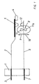
- FIG shown a relay contact.
- the passive contact spring 2 and the active contact spring 6 are clamped.
- the respective springs 2, 6 are by means of Connections 3, 7 led to the outside and are there contactable.
- the passive contact spring 2 has a front contact piece 5 and rests against a stop 4 fixed to the housing.
- the active contact spring 6 is actuated by an actuator 8.
- the term “inside operation” means that the Actuator 8 with its drivers 11, which between them Pick up and guide the active contact spring 6 in the gap between the contact piece 12 and the clamping point in Spring bracket 1 is actuated.
- the actuation is such that the actuator 8 in Arrow direction 9, the active contact spring 6 in the direction of a Closing on the passive contact spring 2 moves while in Opposite direction - arrow direction 10 - the contact is opened.
- the invention is not limited to the active Contact spring 6 between 2 drivers 11 (in FIG. 1 is the one driver designated 11a) is taken; it it is also sufficient for the drivers 11, 11a to be spatially separated from one another separate or movable independently embody.
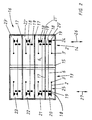
- Such a twin relay 16 is shown in FIG. which consists of two partial relays 13, 14.
- the two Partial relays 13, 14 are electrically connected by a central, insulating partition 15 separated from each other.
- FIG. 2 shows that each partial relay 13, 14 has a total of four contacts, the respective contact either as a break contact, as a make contact or as a changeover contact can be trained.
- Partial relays 13, 14 are arranged because the number is arbitrary is. So there can only be one contact at a time, it can also be a variety of one above the other Contacts are present, as is the case in FIG. 2 using four separate contacts is recognizable.
- the invention is not limited to that such contacts in electrically isolated from each other Chambers 20-23 are arranged.
- the chambers 20-23 are namely by means of corresponding horizontally running partition walls 17 squeezed from each other.
- the invention is not based on this limited. Such horizontally extending partitions 17 can also be omitted.
- the actuator 8 consists essentially of two Share exists, but this is also not necessary solution. It is sufficient here to have only one actuator 19 at a time to be provided on each side of the active Contact spring 6, 6 'attacks.
- Forced leader 18 designated and has only the purpose to prevent NC and NO contacts from closing at the same time could be.
- partial drive 24 mechanically separated and completely autonomous from the partial drive 25 for the right partial relay 14 is.
- Figure 3 shows schematically that this drive system consisting of the partial drives 24, 25 in one level below the partial relay 13, 14. That so above the level for the Partial drives 24, 25, the contact plane is arranged.
- Such a drive system could consist of two separate hinged anchor systems are available and it a sliding anchor system could also be present.
- both are separate Have relay coil, which relay coil over each separate yoke acts on an associated anchor and this emotional.
- Each anchor then acts in the one shown Arrow directions 26, 27 on the assigned sub-drive system 24, 25 of the respective partial relay 13, 14.
- the respective lower chamber 20, 20 'of the respective partial relay 13, 14 are each designed as openers. Characteristic of this both openers is that the active contact spring 6 is connected and therefore both NC contacts are electrical with each other connects so that these two contacts are electrically in series are switched.
- the Relay always consists of a series connection of contacts, but this series connection is an active one Contact spring divides. Because of the electrical connection the active contact spring is no longer necessary this active contact spring to the outside via separate connections to guide and assigned outside of the spring bracket To connect connections. So the connections are internally in the relay without the need for contacting without Connection lines and without corresponding conductor tracks directly already accomplished.
- FIG. 4 shows another exemplary embodiment, that every single contact consists of two active contact springs which is separate from the two drives (Partial drives 24, 25) are moved.
- FIG. 4 shows is the direction of movement of the two partial drives 24, 25 in the opposite direction, because yes the actuation of the active one Contact springs 6, 6 'in opposite directions. This happens characterized in that on one contact spring 6 of the actuator 19 one side rests, while on the other contact spring 6-der Actuator 19 rests on the other side.
- the normally closed contact 28 is opened as soon as one of the two Contact springs 6 or 6 'from the assigned partial drive 24 or 25 is applied.
- the respective active contact spring 6, 6 ' has the associated one External connection 3, 3 ', which is led out of the relay.
- FIG. 5 shows the same conditions as in FIG. 2 is only recognizable that the internal connections 3, 3 'of respective passive contact springs are placed differently, i.e. they are brought out at another point in the spring frame.
- Figure 6 is a variant of Figure 4, wherein the same explanations apply as used with reference to FIG. 4 were given. The only difference is that the respective connection 3, 3 'of the respective active contact spring 6, 6 'is now not led out to the outside of the relay, but instead is formed inside.
- FIG. 7 shows that the respective partial drive system 24, 25 the partial relays 13, 14 are also not aligned one above the other must be arranged, but that the sub-drive system is quite staggered. It is important for This embodiment in turn that the drive system 24th is operated in the direction of arrow 26 while the Drive system 25 of partial relay 23 in the arrow directions 27 is operated separately from the other sub-drive system.
- Figure 6 shows that the upper part of each Partial relay 13, 14 consists of an arrangement as it is based on 6 has already been described, while the lower one Part, consisting of the chambers 30, 31 and 30 ', 31' shows that both the active contact spring and the passive one Contact spring are guided to the outside.
- Characteristic of this Embodiment is so that the two partial relays, 14, 15 out different, stacked relay systems exist, the two relay systems one each have common sub-drive system 24, 25.
- the contacts are in the upper part 33 of this relay operated together, each with two separate Part drive systems 24, 25, while in the lower part 34 Contacts individually, i.e. operated separately.
- the invention is not based on the combination of the parts 33, 34 shown here.
- the invention relates to all of the previously illustrated embodiments which can now be stacked modularly, like this is shown using the superimposed parts 33, 34 with each part 33, 34 with respect to the longitudinal center axis 32 is divided and each part (left side and right side) of the respective part 33, 34 a separate part drive system 24, 25 has.
- Parts 33, 34 each have their own sub-drive system 24, 25 assigned. It is important that this modular structure, like him in Figure 7 by superimposing two such Parts 33, 34 exist, can also be carried out several times, so that other contact constellations, such as in figure 4, 5, 6 were shown in the form of this modular Structure can be arranged one above the other.
- FIG. 7 shows a deviation from those previously shown Embodiments that both the active contact spring as also the passive contact spring with connections, 3, 7 or 3 ', 7' is guided to the outside.
- NC contact is in the monitoring circuit for the Start of the arrangement looped in. The closer is for the Self-retention used. These contacts are essential less burden than for external use available. There is a potential for reducing the required volume. The same applies to insulation to drive.
- twin relay shown here is that a simpler production with the smallest space requirement is guaranteed because external interconnections omitted.
- the user has a great benefit from this because Wiring errors are avoided from the outset and space on an existing circuit board for others Applications and interconnections are given.
- the main advantage for the user is that actually two partial relays in a single housing are arranged, which can be controlled separately, but as one piece in storage and processing can be seen, which significantly simplifies handling.
Landscapes
- Physics & Mathematics (AREA)
- Electromagnetism (AREA)
- Switch Cases, Indication, And Locking (AREA)
Applications Claiming Priority (3)
| Application Number | Priority Date | Filing Date | Title |
|---|---|---|---|
| DE19816878A DE19816878C2 (de) | 1998-04-17 | 1998-04-17 | Zwillingsrelais |
| DE19816878 | 1998-04-17 | ||
| PCT/EP1999/002508 WO1999054905A1 (de) | 1998-04-17 | 1999-04-14 | Zwillingsrelais |
Publications (2)
| Publication Number | Publication Date |
|---|---|
| EP1072049A1 EP1072049A1 (de) | 2001-01-31 |
| EP1072049B1 true EP1072049B1 (de) | 2002-06-26 |
Family
ID=7864721
Family Applications (1)
| Application Number | Title | Priority Date | Filing Date |
|---|---|---|---|
| EP99917980A Expired - Lifetime EP1072049B1 (de) | 1998-04-17 | 1999-04-14 | Zwillingsrelais |
Country Status (5)
| Country | Link |
|---|---|
| US (1) | US6559744B1 (enExample) |
| EP (1) | EP1072049B1 (enExample) |
| JP (1) | JP2002512423A (enExample) |
| DE (2) | DE19816878C2 (enExample) |
| WO (1) | WO1999054905A1 (enExample) |
Families Citing this family (8)
| Publication number | Priority date | Publication date | Assignee | Title |
|---|---|---|---|---|
| ES2445990T3 (es) | 2000-01-28 | 2014-03-06 | Elesta Relays Gmbh | Relé de seguridad, su uso y dispositivo de conexión con tal relé de seguridad |
| US7598828B1 (en) * | 2004-07-28 | 2009-10-06 | Pass & Seymour, Inc. | Protection device with a sandwiched cantilever breaker mechanism |
| DE50114781D1 (de) | 2000-04-03 | 2009-05-07 | Elesta Relays Gmbh | Relais |
| DE102004060370A1 (de) * | 2004-12-15 | 2006-07-06 | Tyco Electronics Austria Gmbh | Elektromagnetisches Relais |
| CH698492B1 (de) * | 2006-03-20 | 2009-08-31 | Elesta Relays Gmbh | Relais. |
| DE102007037333A1 (de) | 2007-08-08 | 2009-02-26 | Daimler Ag | Betätigungsvorrichtung |
| JP6245557B2 (ja) * | 2013-12-13 | 2017-12-13 | パナソニックIpマネジメント株式会社 | 電磁リレー |
| DE102017124567B4 (de) * | 2017-10-20 | 2019-07-25 | sonnen GmbH | Batteriesystem, lokales Stromnetz und Trennschalter |
Family Cites Families (7)
| Publication number | Priority date | Publication date | Assignee | Title |
|---|---|---|---|---|
| GB576623A (en) * | 1943-04-06 | 1946-04-12 | William Warren Triggs | Electromagnetic relays |
| FR1492024A (fr) | 1965-11-15 | 1967-08-18 | Compteurs Et Moteurs Aster | Relais de sécurité perfectionné |
| US3581157A (en) * | 1969-01-17 | 1971-05-25 | Pettibone Corp | Electrical relay circuitry |
| US4959627A (en) * | 1987-12-23 | 1990-09-25 | Nec Corporation | Electromagnet relay |
| DE3834283A1 (de) * | 1988-10-08 | 1990-04-12 | Bosch Gmbh Robert | Umschaltrelais fuer gleichstrommotore mit links- und rechtslaufsteuerung |
| DE19520220C1 (de) | 1995-06-01 | 1996-11-21 | Siemens Ag | Polarisiertes elektromagnetisches Relais |
| DE19606883C1 (de) * | 1996-02-23 | 1997-04-30 | Schrack Components Ag | Elektromagnetisches Relais mit kombinierter Kontakt- und Rückstellfeder |
-
1998
- 1998-04-17 DE DE19816878A patent/DE19816878C2/de not_active Expired - Fee Related
-
1999
- 1999-04-04 US US09/673,769 patent/US6559744B1/en not_active Expired - Lifetime
- 1999-04-14 JP JP2000545169A patent/JP2002512423A/ja active Pending
- 1999-04-14 WO PCT/EP1999/002508 patent/WO1999054905A1/de not_active Ceased
- 1999-04-14 EP EP99917980A patent/EP1072049B1/de not_active Expired - Lifetime
- 1999-04-14 DE DE59901855T patent/DE59901855D1/de not_active Expired - Lifetime
Also Published As
| Publication number | Publication date |
|---|---|
| EP1072049A1 (de) | 2001-01-31 |
| DE19816878C2 (de) | 2003-11-13 |
| WO1999054905A1 (de) | 1999-10-28 |
| JP2002512423A (ja) | 2002-04-23 |
| DE59901855D1 (de) | 2002-08-01 |
| US6559744B1 (en) | 2003-05-06 |
| DE19816878A1 (de) | 1999-10-28 |
Similar Documents
| Publication | Publication Date | Title |
|---|---|---|
| DE4230414C2 (de) | Elektro-pneumatische Steuereinrichtung | |
| DE4440102C1 (de) | Modulare Steuerungsanlage mit integriertem Feldbusanschluß | |
| DE3822340A1 (de) | Solenoidgesteuertes ventil | |
| EP3884742B1 (de) | Basismodul und funktionsmodul für ein schaltschranksystem | |
| DE4004834A1 (de) | Ventilbaugruppe | |
| DE19964156A1 (de) | Elektrisches Gerät | |
| EP0754866B1 (de) | Ventilanordnung | |
| DE102010045629A1 (de) | Einreihige NOT-AUS-Schalter-Kontaktvorrichtung | |
| EP1072049B1 (de) | Zwillingsrelais | |
| CH629059A5 (de) | Mit anschlussorganen fuer anschlussdraehte versehene elektrische anschlussplatte. | |
| EP0629783B1 (de) | Kombinierte Steuerung von Pneumatik- und Hydraulikventilen | |
| DE3910913C2 (de) | Pneumatische oder hydraulische Ventileinheit | |
| EP0740082A1 (de) | Modularer elektrischer Teil für einen Ventilblock | |
| DE3943752C2 (de) | Pneumatische oder hydraulische Ventileinheit | |
| CH675036A5 (enExample) | ||
| DE2817036A1 (de) | Sicherheitsfedersatz, zugehoerig zu einem relais zur erfuellung erhoehter sicherheitsbestimmungen | |
| EP1878958B1 (de) | Ventilanordnung | |
| DE1160511B (de) | Koordinatenwaehler fuer Fernmeldeanlagen, insbesondere Fernsprechvermittlungsanlagen | |
| EP1086265B1 (de) | Luftzuführblock für eine webmaschine | |
| EP0124751B1 (de) | Steuerschalter für eine Fahrzeugsitz-Verstelleinrichtung | |
| EP2099048B1 (de) | Modulare Sicherheitssteuerung und Sicherheits-Relaismodul | |
| DE19851507A1 (de) | Relais mit Koppelelement | |
| DE2057546A1 (de) | Signalschalteinrichtung | |
| DE2904677A1 (de) | Relais-federsatz mit rueckstellelement | |
| EP1403889B1 (de) | Positionsschalter |
Legal Events
| Date | Code | Title | Description |
|---|---|---|---|
| PUAI | Public reference made under article 153(3) epc to a published international application that has entered the european phase |
Free format text: ORIGINAL CODE: 0009012 |
|
| 17P | Request for examination filed |
Effective date: 20001018 |
|
| AK | Designated contracting states |
Kind code of ref document: A1 Designated state(s): DE |
|
| GRAG | Despatch of communication of intention to grant |
Free format text: ORIGINAL CODE: EPIDOS AGRA |
|
| 17Q | First examination report despatched |
Effective date: 20011120 |
|
| GRAG | Despatch of communication of intention to grant |
Free format text: ORIGINAL CODE: EPIDOS AGRA |
|
| GRAH | Despatch of communication of intention to grant a patent |
Free format text: ORIGINAL CODE: EPIDOS IGRA |
|
| GRAH | Despatch of communication of intention to grant a patent |
Free format text: ORIGINAL CODE: EPIDOS IGRA |
|
| GRAA | (expected) grant |
Free format text: ORIGINAL CODE: 0009210 |
|
| AK | Designated contracting states |
Kind code of ref document: B1 Designated state(s): DE |
|
| REF | Corresponds to: |
Ref document number: 59901855 Country of ref document: DE Date of ref document: 20020801 |
|
| PLBE | No opposition filed within time limit |
Free format text: ORIGINAL CODE: 0009261 |
|
| STAA | Information on the status of an ep patent application or granted ep patent |
Free format text: STATUS: NO OPPOSITION FILED WITHIN TIME LIMIT |
|
| 26N | No opposition filed |
Effective date: 20030327 |
|
| PGFP | Annual fee paid to national office [announced via postgrant information from national office to epo] |
Ref country code: DE Payment date: 20150422 Year of fee payment: 17 |
|
| REG | Reference to a national code |
Ref country code: DE Ref legal event code: R119 Ref document number: 59901855 Country of ref document: DE |
|
| PG25 | Lapsed in a contracting state [announced via postgrant information from national office to epo] |
Ref country code: DE Free format text: LAPSE BECAUSE OF NON-PAYMENT OF DUE FEES Effective date: 20161101 |