EP0629783B1 - Kombinierte Steuerung von Pneumatik- und Hydraulikventilen - Google Patents
Kombinierte Steuerung von Pneumatik- und Hydraulikventilen Download PDFInfo
- Publication number
- EP0629783B1 EP0629783B1 EP94103405A EP94103405A EP0629783B1 EP 0629783 B1 EP0629783 B1 EP 0629783B1 EP 94103405 A EP94103405 A EP 94103405A EP 94103405 A EP94103405 A EP 94103405A EP 0629783 B1 EP0629783 B1 EP 0629783B1
- Authority
- EP
- European Patent Office
- Prior art keywords
- valve
- control
- valve station
- valves
- station according
- Prior art date
- Legal status (The legal status is an assumption and is not a legal conclusion. Google has not performed a legal analysis and makes no representation as to the accuracy of the status listed.)
- Expired - Lifetime
Links
Images
Classifications
-
- F—MECHANICAL ENGINEERING; LIGHTING; HEATING; WEAPONS; BLASTING
- F15—FLUID-PRESSURE ACTUATORS; HYDRAULICS OR PNEUMATICS IN GENERAL
- F15B—SYSTEMS ACTING BY MEANS OF FLUIDS IN GENERAL; FLUID-PRESSURE ACTUATORS, e.g. SERVOMOTORS; DETAILS OF FLUID-PRESSURE SYSTEMS, NOT OTHERWISE PROVIDED FOR
- F15B13/00—Details of servomotor systems ; Valves for servomotor systems
- F15B13/02—Fluid distribution or supply devices characterised by their adaptation to the control of servomotors
- F15B13/06—Fluid distribution or supply devices characterised by their adaptation to the control of servomotors for use with two or more servomotors
- F15B13/08—Assemblies of units, each for the control of a single servomotor only
- F15B13/0803—Modular units
- F15B13/0846—Electrical details
- F15B13/0857—Electrical connecting means, e.g. plugs, sockets
-
- F—MECHANICAL ENGINEERING; LIGHTING; HEATING; WEAPONS; BLASTING
- F15—FLUID-PRESSURE ACTUATORS; HYDRAULICS OR PNEUMATICS IN GENERAL
- F15B—SYSTEMS ACTING BY MEANS OF FLUIDS IN GENERAL; FLUID-PRESSURE ACTUATORS, e.g. SERVOMOTORS; DETAILS OF FLUID-PRESSURE SYSTEMS, NOT OTHERWISE PROVIDED FOR
- F15B13/00—Details of servomotor systems ; Valves for servomotor systems
- F15B13/02—Fluid distribution or supply devices characterised by their adaptation to the control of servomotors
- F15B13/06—Fluid distribution or supply devices characterised by their adaptation to the control of servomotors for use with two or more servomotors
- F15B13/08—Assemblies of units, each for the control of a single servomotor only
- F15B13/0803—Modular units
- F15B13/0807—Manifolds
- F15B13/0814—Monoblock manifolds
-
- F—MECHANICAL ENGINEERING; LIGHTING; HEATING; WEAPONS; BLASTING
- F15—FLUID-PRESSURE ACTUATORS; HYDRAULICS OR PNEUMATICS IN GENERAL
- F15B—SYSTEMS ACTING BY MEANS OF FLUIDS IN GENERAL; FLUID-PRESSURE ACTUATORS, e.g. SERVOMOTORS; DETAILS OF FLUID-PRESSURE SYSTEMS, NOT OTHERWISE PROVIDED FOR
- F15B13/00—Details of servomotor systems ; Valves for servomotor systems
- F15B13/02—Fluid distribution or supply devices characterised by their adaptation to the control of servomotors
- F15B13/06—Fluid distribution or supply devices characterised by their adaptation to the control of servomotors for use with two or more servomotors
- F15B13/08—Assemblies of units, each for the control of a single servomotor only
- F15B13/0803—Modular units
- F15B13/0846—Electrical details
- F15B13/086—Sensing means, e.g. pressure sensors
-
- F—MECHANICAL ENGINEERING; LIGHTING; HEATING; WEAPONS; BLASTING
- F15—FLUID-PRESSURE ACTUATORS; HYDRAULICS OR PNEUMATICS IN GENERAL
- F15B—SYSTEMS ACTING BY MEANS OF FLUIDS IN GENERAL; FLUID-PRESSURE ACTUATORS, e.g. SERVOMOTORS; DETAILS OF FLUID-PRESSURE SYSTEMS, NOT OTHERWISE PROVIDED FOR
- F15B13/00—Details of servomotor systems ; Valves for servomotor systems
- F15B13/02—Fluid distribution or supply devices characterised by their adaptation to the control of servomotors
- F15B13/06—Fluid distribution or supply devices characterised by their adaptation to the control of servomotors for use with two or more servomotors
- F15B13/08—Assemblies of units, each for the control of a single servomotor only
- F15B13/0803—Modular units
- F15B13/0846—Electrical details
- F15B13/0867—Data bus systems
-
- F—MECHANICAL ENGINEERING; LIGHTING; HEATING; WEAPONS; BLASTING
- F15—FLUID-PRESSURE ACTUATORS; HYDRAULICS OR PNEUMATICS IN GENERAL
- F15B—SYSTEMS ACTING BY MEANS OF FLUIDS IN GENERAL; FLUID-PRESSURE ACTUATORS, e.g. SERVOMOTORS; DETAILS OF FLUID-PRESSURE SYSTEMS, NOT OTHERWISE PROVIDED FOR
- F15B13/00—Details of servomotor systems ; Valves for servomotor systems
- F15B13/02—Fluid distribution or supply devices characterised by their adaptation to the control of servomotors
- F15B13/06—Fluid distribution or supply devices characterised by their adaptation to the control of servomotors for use with two or more servomotors
- F15B13/08—Assemblies of units, each for the control of a single servomotor only
- F15B13/0803—Modular units
- F15B13/0875—Channels for electrical components, e.g. for cables or sensors
-
- F—MECHANICAL ENGINEERING; LIGHTING; HEATING; WEAPONS; BLASTING
- F15—FLUID-PRESSURE ACTUATORS; HYDRAULICS OR PNEUMATICS IN GENERAL
- F15B—SYSTEMS ACTING BY MEANS OF FLUIDS IN GENERAL; FLUID-PRESSURE ACTUATORS, e.g. SERVOMOTORS; DETAILS OF FLUID-PRESSURE SYSTEMS, NOT OTHERWISE PROVIDED FOR
- F15B13/00—Details of servomotor systems ; Valves for servomotor systems
- F15B13/02—Fluid distribution or supply devices characterised by their adaptation to the control of servomotors
- F15B13/06—Fluid distribution or supply devices characterised by their adaptation to the control of servomotors for use with two or more servomotors
- F15B13/08—Assemblies of units, each for the control of a single servomotor only
- F15B13/0803—Modular units
- F15B13/0878—Assembly of modular units
- F15B13/0885—Assembly of modular units using valves combined with other components
- F15B13/0889—Valves combined with electrical components
-
- F—MECHANICAL ENGINEERING; LIGHTING; HEATING; WEAPONS; BLASTING
- F15—FLUID-PRESSURE ACTUATORS; HYDRAULICS OR PNEUMATICS IN GENERAL
- F15B—SYSTEMS ACTING BY MEANS OF FLUIDS IN GENERAL; FLUID-PRESSURE ACTUATORS, e.g. SERVOMOTORS; DETAILS OF FLUID-PRESSURE SYSTEMS, NOT OTHERWISE PROVIDED FOR
- F15B21/00—Common features of fluid actuator systems; Fluid-pressure actuator systems or details thereof, not covered by any other group of this subclass
- F15B21/08—Servomotor systems incorporating electrically operated control means
- F15B21/085—Servomotor systems incorporating electrically operated control means using a data bus, e.g. "CANBUS"
-
- Y—GENERAL TAGGING OF NEW TECHNOLOGICAL DEVELOPMENTS; GENERAL TAGGING OF CROSS-SECTIONAL TECHNOLOGIES SPANNING OVER SEVERAL SECTIONS OF THE IPC; TECHNICAL SUBJECTS COVERED BY FORMER USPC CROSS-REFERENCE ART COLLECTIONS [XRACs] AND DIGESTS
- Y10—TECHNICAL SUBJECTS COVERED BY FORMER USPC
- Y10T—TECHNICAL SUBJECTS COVERED BY FORMER US CLASSIFICATION
- Y10T137/00—Fluid handling
- Y10T137/7722—Line condition change responsive valves
- Y10T137/7837—Direct response valves [i.e., check valve type]
- Y10T137/7879—Resilient material valve
- Y10T137/788—Having expansible port
-
- Y—GENERAL TAGGING OF NEW TECHNOLOGICAL DEVELOPMENTS; GENERAL TAGGING OF CROSS-SECTIONAL TECHNOLOGIES SPANNING OVER SEVERAL SECTIONS OF THE IPC; TECHNICAL SUBJECTS COVERED BY FORMER USPC CROSS-REFERENCE ART COLLECTIONS [XRACs] AND DIGESTS
- Y10—TECHNICAL SUBJECTS COVERED BY FORMER USPC
- Y10T—TECHNICAL SUBJECTS COVERED BY FORMER US CLASSIFICATION
- Y10T137/00—Fluid handling
- Y10T137/8593—Systems
- Y10T137/87169—Supply and exhaust
- Y10T137/87217—Motor
Definitions
- the invention relates to a valve station for use in connection with the control of fluid-actuated devices, for example working cylinders, with a fluid distributor having internal fluid channels, which is equipped with electrically actuated pneumatic valves that communicate with the fluid channels, and with a signal distributor, from which the Pneumatic valves receive their electrical actuation signals.
- Valve stations of this type which are also referred to as valve terminals, can be found, for example, in DE-U-92 11 109. They have a plate-like fluid distributor, inside which there are fluid channels that communicate with the pneumatic valves arranged on it.
- a signal distributor for example designed as a control unit, is in electrical connection with the valve actuators of the pneumatic valves and supplies the necessary electrical actuation signals. In this way, the valves can be switched as required in order to control connected fluid-operated devices with regard to their mode of operation.
- Such a valve station allows the actuation of fluid-operated devices from a central location. This facilitates both the set-up and later operation, including monitoring of machines and systems that are equipped with fluid-operated devices. If these fluid-actuated devices are not only pneumatically actuated but also hydraulically actuated devices, so far, however, a completely separate control has been carried out, since in hydraulic operation different parameters come into play than in pneumatics. The constructional effort is therefore enormous, especially with regard to the electrical and electronics that are required to control the different types of valves.
- the object of the present invention is to reduce the structural outlay incurred in connection with the parallel operation of pneumatic and hydraulic valves.
- valve station is designed for combined control of both pneumatic valves and hydraulic valves, and has at least one control connection for connection to at least one electrically actuable valve drive of a hydraulic valve.
- Such a valve station is also known from DE-A-39 10 913 which is suitable for equipping with both hydraulic and pneumatic valves. However, a combination of the two types of valves is not intended.
- both pneumatic valves and hydraulic valves can be controlled and actuated via a single valve station, which allows an optimal function linkage. It is possible to control both types of valve via a common control unit, which is particularly advantageous if the control unit is formed by the signal distributor of the valve station and forms a direct part of the same. It has been recognized that pneumatics and hydraulics can be linked in this way without mutual interference, which, above all, considerably simplifies the installation work and the operation of complex systems or machines.
- control connections would be conceivable, in particular, connecting devices which are installed in or on the fluid distributor and with which the valve drives of the hydraulic valves can be automatically coupled when the assigned fluid distributor is equipped.
- control connections for the hydraulic valves as connections for at least one signal conductor, via which external hydraulic valves can be connected, that is, hydraulic valves that do not form a direct part of the valve station.
- valve station In the case of the control of external hydraulic valves, it is expedient to provide the assigned control connections in at least one control part of the valve station, which can be integrated in the signal distributor, but is expediently a separate component or module which forms a fixed, possibly detachable part of the valve station . If several such control parts are provided, the valve station can be constructed as required; one could speak of a modular valve station.
- valve station can also have further outputs and / or inputs for control signals, which in particular are also provided on at least one control part.
- Signal conductors can be connected to them, in particular to Monitoring devices such as sensors or the like. to lead.
- the valve station 1 shown in FIG. 1 contains a fluid distributor 2 for pneumatic pressure medium.
- a plurality of pneumatic valves 4, which are multi-way valves, are detachably arranged on an assembly surface 3 of the fluid distributor 2.
- the valve channels of the pneumatic valves 4, not shown in any more detail, communicate with internal fluid channels 5, that is to say inside the fluid distributor 2, which are only partially indicated by dashed lines.
- One of these fluid channels 5 is expedient a feed channel 6, which can be connected to a pressure medium source P via a connection opening 13 and which, on the other hand, opens out in the region of each valve 4 to the mounting surface 3.
- a fluid channel 5 serving as an exhaust air duct 7 has a corresponding course, to the central outlet opening 14 of which a muffler or an exhaust air duct which holds the exhaust air can be connected.
- Each pneumatic valve 4 communicates both with the feed channel 6 and with the exhaust air channel 7 via the openings on the assembly surface 3. Furthermore, each pneumatic valve 4 communicates with at least one and in particular two consumer channels 8 of the fluid distributor 2, which open on the outside of the fluid distributor 2, so that pressure medium lines 12 can be connected, which lead to pneumatically actuated devices 15. In the exemplary embodiment, for the sake of simplicity, only such a device 15, which is a working cylinder, is shown schematically.
- connected pneumatically actuated devices can be supplied with compressed air or vented.
- the pneumatic valves 4 are actuated electrically. They each contain an electrically actuable valve drive 16, which regularly contains at least one electromagnet, and which is preferably a so-called solenoid valve. Each valve drive 16 is in electrical connection with an electrical conductor arrangement 17, which extends along the fluid distributor 2, in particular within the fluid distributor 2 in a suitable channel. For the connection to the valve drives 16, electrical plug-in means are expediently provided, so that the electrical connection is established automatically during valve assembly.
- the electrical conductor arrangement 17 is based on a signal distributor 18 which is arranged on an end face of the fluid distributor 2 and in particular is permanently attached.
- the signal distributor 18 is formed by a control unit 22 which contains a control program and in particular is freely programmable, so that autonomous operation is possible.
- An interface 23 enables the connection of a computer (PC) for programming and setup purposes.
- Further interfaces 24 form outputs and / or inputs of a field bus, via the further signal distributors of other valve stations can be connected.
- a signal distributor 18 a fieldbus communication unit without its own control program, which communicates with an external control unit and receives the corresponding signals from the latter, on the basis of which the actuation signals are distributed to the pneumatic valves 4.
- a fieldbus solution conventional 1: 1 wiring would also be possible, in particular using so-called multipole lines.
- the signal distributor could be a simple bus that drives the valve drives.
- control part 25, 26 which communicate with the control unit 22 of the valve station via electrical conductors, not shown, by connecting them to the signal distributor 18, for example.
- the corresponding electrical conductors are not shown in the drawing, since they run inside the control parts 25, 26.
- Each control part 25, 26 expediently contains a conductor section which is continuous in the direction of attachment, the conductor sections complementing one another in the assembled state to form a continuous conductor strand.
- control connections are on one of the control parts 25 27 provided, which are accessible from the outside. They are designed so that they can be used to control hydraulic valves 28 to which electrically actuable valve drives 32 are assigned.
- Each control connection 27 represents a control signal output which is in electrical connection with the individual valve drives 32 via one or more signal conductors 33.
- the signal conductors 33 can be wires or cables that can be laid easily and flexibly, so that the hydraulic valves 28 with their valve drives 32 can be installed practically any distance from the valve terminal 1.
- the valve drives 32 receive the control signals required for actuation, which are caused by the control unit 22, via the signal conductors 33 and the control connections 27.
- each control connection 27 an electrical and / or electronic output stage which is adapted to the valve drive to be controlled and which processes the electrical actuation signals coming from the control unit 22 in such a way that they act as direct actuation signals for the valve drives 32 of the hydraulic valves 28 can be used.
- control connections of the control part 25 are preferably designed as electrical plug connections, so that the signal conductors 33 can be connected or disconnected quickly.
- the valve station 1 of the exemplary embodiment is designed to control or actuate four hydraulic valves 28, which is why the relevant control part 25 has four control signal outputs or control connections 27. It goes without saying that a different number of control connections 27 can also be provided, for example only one.
- Each hydraulic valve 28 communicates with a system of hydraulic lines, indicated by arrows 34, which establish the connection to a supply source and a tank.
- a common line system 34 can be provided for all hydraulic valves 28.
- the hydraulic valves 28 are connected via consumer lines, which are indicated by further arrows 35, connected to the hydraulically operated devices, only such a device 36 is shown in simplified form, which is a hydraulic working cylinder. It can be seen that the hydraulic valves 28 can be attached directly to the device 36 to be actuated.
- the control part 25 forms a module of the valve station 1.
- the valve station 1 can be constructed in a modular manner to the desired extent.
- further control parts 25 can therefore be provided, which have control signal outputs for control connections 27 forming hydraulic valves.
- at least one further control part 26 which is provided with outputs and / or inputs 37, via which signals can be transmitted to and / or from other devices which are required for the operation of the valve station or from the latter be operated.
- outputs and / or inputs 37 enable the connection of monitoring devices such as sensors or the like, on the basis of whose signals the control unit 22 carries out the distribution of the electrical actuation signals.
- a control part 25 is provided exclusively for the control of hydraulic valves 28, while a control part 26 is provided exclusively with outputs and / or inputs 37 for monitoring devices.
- a single control part can contain a mixture of inputs and outputs or control connections of various types.
- valve station 1 which is suitable for the combined actuation of both pneumatic valves 4 and hydraulic valves 28.
- a common control unit 22 is sufficient to control both types of valve, which results in a relatively low construction effort, particularly with regard to the electronics side. It is possible to precisely coordinate the actuation of the pneumatic valves and the hydraulic valves, an actuation which is independent of one another being able to be implemented. Due to the modular structure of the valve station, it is also possible to operate it with only one of the two valve types if necessary. One could omit the control block 25 and would have a valve station equipped and working exclusively with pneumatic valves. It would also be possible to omit the fluid distributor 2 with all pneumatic valves 4 and the remaining part of the valve station exclusively for actuation and actuation of hydraulic valves 28 to use.
- the fluid distributor 2 as such also be of modular construction, which is the case in the exemplary embodiment.
- the fluid distributor 2 is subdivided into a plurality of length sections which form adjoining distributor modules 38, each of which is equipped with at least one pneumatic valve 4.
- the pneumatic part can thus be expanded practically as desired.
- valve assembly 2 schematically shows the possibility of arranging both pneumatic valves 4 and hydraulic valves 28 directly on a fluid distributor 2 'of the valve station 1.
- the electrical conductor arrangement 17 emanating from the signal distributor 18 serves for the simultaneous supply of both valve types with the necessary electrical actuation signals.
- the control connections 27 are provided here in the area of the assembly locations for the hydraulic valves 28 and are connected to the electrical conductor arrangement 17, the electrical valve drives 32 of the hydraulic valves 28 advantageously being automatically connected to the control connections during valve assembly 27 can be connected.
- one can also provide a separate electrical conductor arrangement for the hydraulic valves 28 (not shown), which, however, expediently extends parallel to that for the pneumatic valves 4.
- the fluid distributor 2 'contains two mutually independent channel systems for the two types of valves, which is indicated in FIG. 2 by arrows P p / R p and P h / R h . Both channel systems can run according to the internal channel profile in the fluid distributor 2 of the embodiment according to FIG. 1. However, it is advantageous here if the fluid distributor 2 has its own distributor module 39, 39 'for each valve type, each of which has its own channel system. In the exemplary embodiment, two such distribution modules 39, 39 'are provided, one (39) of which is equipped with a pneumatic and the other (39') with a hydraulic channel system. A fluidic connection between distributor modules 39, 39 'of different types is not necessary in this case, but the electrical series connection is expediently retained. The distributor modules 39, 39 'can be subdivided even more modularly.
- valve station 1 can also have control parts 25, 26 (not shown in more detail), via which a signal connection to external devices takes place. You can combine the possibilities of setting up a valve station shown using the two exemplary embodiments.
- both the control parts 25, 26 and the distribution modules 38; 39, 39 'in a linear mounting direction 40 can be successively attached to one another, the control parts 25, 26 on the one hand and the distributor modules 38; 39, 39 'are expediently attached to opposite sides of the signal distributor 18, which itself expediently has a block-like structure.
Landscapes
- Engineering & Computer Science (AREA)
- Physics & Mathematics (AREA)
- Fluid Mechanics (AREA)
- Mechanical Engineering (AREA)
- General Engineering & Computer Science (AREA)
- Chemical & Material Sciences (AREA)
- Analytical Chemistry (AREA)
- Fluid-Pressure Circuits (AREA)
- Valve Housings (AREA)
- Servomotors (AREA)
- Valve Device For Special Equipments (AREA)
Description
- Die Erfindung betrifft eine Ventilstation zur Verwendung im Zusammenhang mit der Steuerung fluidbetätigbarer Einrichtungen, beispielsweise von Arbeitszylindern, mit einem über interne Fluidkanäle verfügenden Fluidverteiler, der mit elektrisch betätigbaren Pneumatikventilen bestückt ist, die mit den Fluidkanälen kommunizieren, und mit einem Signalverteiler, von dem aus die Pneumatikventile ihre elektrischen Betätigungssignale erhalten.
- Ventilstationen dieser Art, die auch als Ventilinseln bezeichnet werden, gehen z.B. aus der DE-U-92 11 109 hervor. Sie verfügen über einen plattenähnlichen Fluidverteiler, in dessen Innerem Fluidkanäle verlaufen, die mit den auf ihm angeordneten Pneumatikventilen kommunizieren.Ein z.B. als Steuereinheit ausgebildeter Signalverteiler steht in elektrischer Verbindung mit den Ventilantrieben der Pneumatikventile und liefert die erforderlichen elektrischen Betätigungssignale. Auf diese Weise können die Ventile bedarfsgemäß geschaltet werden, um angeschlossene fluidbetätigbare Einrichtungen hinsichtlich ihrer Arbeitsweise zu steuern.
- Eine derartige Ventilstation erlaubt die Ansteuerung fluidbetätigbarer Einrichtungen von zentraler Stelle aus. Dies erleichtert sowohl den Aufbau als auch den späteren Betrieb einschließlich überwachung von Maschinen und Anlagen, die mit fluidbetätigbaren Einrichtungen ausgestattet sind. Handelt es sich bei diesen fluidbetätigbaren Einrichtungen neben pneumatisch betätigbaren auch um hydraulisch betätigbare, so hat man bisher allerdings eine völlig separate Ansteuerung vorgenommen, da im Hydraulikbetrieb andere Parameter zum Tragen kommen als in der Pneumatik. Der bauliche Aufwand ist deshalb enorm, insbesondere hinsichtlich der Elektrik und Elektronik, die für die Ansteuerung der unterschiedlichen Ventilarten benötigt wird.
- Die Aufgabe der vorliegenden Erfindung besteht darin, den im Zusammenhang mit dem parallelen Betrieb pneumatischer und hydraulischer Ventile anfallenden baulichen Aufwand zu reduzieren.
- Diese Aufgabe wird dadurch gelöst, daß die Ventilstation zur kombinierten Ansteuerung sowohl von Pneumatikventilen als auch von Hydraulikventilen ausgelegt ist, wobei sie über mindestens einen Steueranschluß zur Verbindung mit mindestens einem elektrisch betätigbaren Ventilantrieb eines Hydraulikventiles verfügt.
- Auch aus der DE-A-39 10 913 ist eine derartige Ventilstation bekannt die für die Bestückung sowohl mit hydraulischen als auch mit pneumatischen Ventilen geeignet ist. Eine Kombination der beiden Ventilarten ist jedoch nicht vorgesehen.
- Somit lassen sich über eine einzige Ventilstation sowohl Pneumatikventile als auch Hydraulikventile ansteuern und betätigen, was eine optimale Funktionsverknüpfung erlaubt. Man hat die Möglichkeit, beide Ventilarten über eine gemeinsame Steuereinheit anzusteuern, was von besonderem Vorteil ist, wenn die Steuereinheit von dem Signalverteiler der Ventilstation gebildet ist und einen unmittelbaren Bestandteil derselben bildet. Es ist erkannt worden, daß sich auf diese Weise Pneumatik und Hydraulik ohne gegenseitige Beeinträchtigung verknüpfen läßt, was vor allem die Installationsarbeiten und den Betrieb komplexer Anlagen oder Maschinen erheblich vereinfacht.
- Vorteilhafte Weiterbildungen der Erfindung sind in den Unteransprüchen aufgeführt.
- Es wäre denkbar, den Fluidverteiler der Ventilstation unmittelbar mit Hydraulikventilen zu bestücken, in welchem Falle man zweckmäßigerweise voneinander getrennte pneumatische und hydraulische Kanalsysteme vorsehen würde. Als Steueranschlüsse wären in diesem Falle insbesondere von Steckmitteln gebildete Anschlußeinrichtungen denkbar, die im oder am Fluidverteiler verlegt sind und mit denen die Ventilantriebe der Hydraulikventile beim Bestücken des zugeordneten Fluidverteilers automatisch kuppelbar sind. Um die Ventilstation vor leckagebedingten Flüssigkeitsverunreinigungen zu schützen, sieht eine derzeit als zweckmäßiger angesehene Ausführungsform allerdings vor, die Steueranschlüsse für die Hydraulikventile als Anschlüsse für mindestens einen Signalleiter auszubilden, über den sich externe Hydraulikventile anschließen lassen, also Hydraulikventile, die nicht unmittelbar Bestandteil der Ventilstation bilden. Natürlich ist auch eine Kombination der genannten Bauformen möglich.
- Im Falle der Ansteuerung externer Hydraulikventile ist es zweckmäßig, die zugeordneten Steueranschlüsse in mindestens einem Ansteuerteil der Ventilstation vorzusehen, das in den Signalverteiler integriert sein kann, zweckmäßigerweise jedoch ein separates Bauteil bzw. Modul ist, welches einen festen, unter Umständen lösbaren Bestandteil der Venilstation bildet. Sind mehrere derartige Ansteuerteile vorgesehen, läßt sich die Ventilstation bedarfsgemäß aufbauen, man könnte von einer modularen Ventilstation sprechen.
- Außer den Steueranschlüssen für die Hydraulikventile kann die Ventilstation noch weitere Ausgänge und/oder Eingänge für Steuersignale aufweisen, die insbesondere ebenfalls an mindestens einem Ansteuerteil vorgesehen sind. An sie können Signalleiter angeschlossen werden, die insbesondere zu Überwachungseinrichtungen wie Sensoren od.dgl. führen.
- Nachfolgend wird die Erfindung anhand der beiliegenden Zeichnung näher erläutert. In dieser zeigen:
- Fig. 1
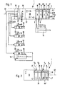
- eine erste Bauform der erfindungsgemäßen Ventilstation in Draufsicht und stark vereinfacht, wobei die Ventilstation unmittelbar lediglich mit Pneumatikventilen ausgestattet ist, während die Hydraulikventile extern angeordnet und über geeignete Signalleiter angesteuert werden, und
- Fig. 2
- eine Bauform der Ventilstation, bei der der Fluidverteiler sowohl mit Pneumatikventilen als auch mit Hydraulikventilen bestückt ist.
- Die in Fig. 1 gezeigte Ventilstation 1 enthält einen Fluidverteiler 2 für pneumatisches Druckmittel. Auf einer Bestückungsfläche 3 des Fluidverteilers 2 sind mehrere Pneumatikventile 4 lösbar angeordnet, bei denen es sich um Mehrwegeventile handelt. Die nicht näher dargestellten Ventilkanäle der Pneumatikventile 4 kommunizieren mit internen, d. h. im Innern des Fluidverteilers 2 verlaufenden Fluidkanälen 5, die lediglich teilweise gestrichtelt angedeutet sind. Einer dieser Fluidkanäle 5 ist zweckmäßigerweise ein Speisekanal 6, der über eine Anschlußöffnung 13 an eine Druckmittelquelle P anschließbar ist und der andererseits im Bereich eines jeden Ventils 4 zur Bestückungsfläche 3 ausmündet. Einen entsprechenden Verlauf hat ein als Abluftkanal 7 dienender Fluidkanal 5, an dessen zentrale Austrittsöffnung 14 ein Schalldämpfer oder eine die Abluft fassende Abluftleitung anschließbar ist. Über die Mündungen an der Bestückungsfläche 3 kommuniziert jedes Pneumatikventil 4 sowohl mit dem Speisekanal 6 als auch mit dem Abluftkanal 7. Des weiteren kommuniziert jedes Pneumatikventil 4 mit mindestens einem und insbesondere zwei Verbraucherkanälen 8 des Fluidverteilers 2, die an der Außenseite des Fluidverteilers 2 münden, so daß Druckmittelleitungen 12 angeschlossen werden können, die zu pneumatisch betätigbaren Einrichtungen 15 führen. Beim Ausführungsbeispiel ist der Einfachheit halber nur eine solche Einrichtung 15 schematisch abgebildet, bei der es sich um einen Arbeitszylinder handelt.
- Entsprechend der Schaltstellung der einzelnen Pneumatikventile 4 können angeschlossene pneumatisch betätigbare Einrichtungen mit Druckluft versorgt oder entlüftet werden.
- Die Betätigung der Pneumatikventile 4 erfolgt elektrisch. Sie enthalten jeweils einen elektrisch betätigbaren Ventilantrieb 16, der regelmäßig mindestens einen Elektromagneten enthält, und bei dem es sich vorzugsweise um ein sogenanntes Magnetventil handelt. Jeder Ventilantrieb 16 steht in elektrischer Verbindung mit einer elektrischen Leiteranordnung 17, die sich längs des Fluidverteilers 2 erstreckt, und zwar insbesondere innerhalb des Fluidverteilers 2 in einem geeigneten Kanal. Zur Verbindung mit den Ventilantrieben 16 sind zweckmäßigerweise elektrische Steckmittel vorgesehen, so daß bei der Ventilmontage automatisch die elektrische Verbindung hergestellt wird.
- Die elektrische Leiteranordnung 17 geht von einem Signalverteiler 18 aus, der an einer Stirnseite des Fluidverteilers 2 angeordnet und insbesondere fest angebaut ist. Beim Ausführungsbeispiel ist der Signalverteiler 18 von einer Steuereinheit 22 gebildet, die ein Steuerprogramm enthält und insbesondere frei programmierbar ist, so daß ein autarker Betrieb möglich ist. Eine Schnittstelle 23 ermöglicht zu Programmier- und Einrichtzwecken den Anschluß eines Computers (PC). Weitere Schnittstellen 24 bilden Aus- und/oder Eingänge eines Feldbusses, über den weitere Signalverteiler anderer Ventilstationen angeschlossen werden können.
- Es wäre auch denkbar, als Signalverteiler 18 eine Feldbus-Kommunikationseinheit ohne eigenes Steuerprogramm vorzusehen, die mit einer externen Steuereinheit kommuniziert und von dieser die entsprechenden Signale erhält, auf Grund derer die Betätigungssignale an die Pneumatikventile 4 verteilt werden. Anstelle einer Feldbus-Lösung wäre auch eine konventionelle 1:1-Verdrahtung möglich, insbesondere unter Verwendung sogenannter Multipolleitungen. Sollte jedem Ventilantrieb 16 eine eigene, insbesondere integrierte Feldbus-Kommunikationseinheit zugeordnet sein, so könnte der Signalverteiler ein einfacher Bus sein, der die Ventilantriebe anfährt.
- Die Ventilinsel gemäß Fig. 1 enthält des weiteren zwei Ansteuerteile 25, 26, die über nicht näher dargestellte elektrische Leiter mit der Steuereinheit 22 der Ventilstation kommunizieren, indem sie beispielsgemäß an den Signalverteiler 18 angeschlossen sind. Die entsprechenden elektrischen Leiter sind in der Zeichnung nicht ersichtlich, da sie im Innern der Ansteuerteile 25, 26 verlaufen. Zweckmäßigerweise enthält jedes Ansteuerteil 25, 26 einen in Anbaurichtung durchgehenden Leiterabschnitt, wobei sich die Leiterabschnitte im zusammengebauten Zustand zu einem durchgehenden Leiterstrang ergänzen.
- An einem der Ansteuerteile 25 sind mehrere Steueranschlüsse 27 vorgesehen, die von außen her zugänglich sind. Sie sind so ausgelegt, daß über sie die Ansteuerung von Hydraulikventilen 28 möglich ist, denen elektrisch betätigbare Ventilantriebe 32 zugeordnet sind. Jeder Steueranschluß 27 repräsentiert einen Steuersignal-Ausgang, der über einen oder mehrere Signalleiter 33 mit den einzelnen Ventilantrieben 32 in elektrischer Verbindung steht. Bei den Signalleitern 33 kann es sich um Drähte oder Kabel handeln, die sich leicht und flexibel verlegen lassen, so daß die Hydraulikventile 28 mit ihren Ventilantrieben 32 praktisch beliebig weit entfernt von der Ventilinsel 1 installiert sein können. Die Ventilantriebe 32 empfangen über die Signalleiter 33 und die Steueranschlüsse 27 die zur Betätigung erforderlichen Steuersignale, die von der Steuereinheit 22 verursacht werden.
- Damit die Steuersignale nach Verlassen der Ventilinsel 1 nicht mehr aufbereitet werden müssen, ist es empfehlenswert, jedem Steueranschluß 27 eine an den anzusteuernden Ventilantrieb angepaßte elektrische und/oder elektronische Ausgangsstufe zuzuordnen, die die von der Steuereinheit 22 kommenden elektrischen Betätigungssignale so aufarbeitet, daß sie als unmittelbare Betätigungssignale für die Ventilantriebe 32 der Hydraulikventile 28 verwendbar sind.
- Die betreffenden Ausgangsstufen sind in das zugeordnete Ansteuerteil 25 integriert und daher in den Abbildungen nicht sichtbar.
- Die Steueranschlüsse des Ansteuerteils 25 sind vorzugsweise als elektrische Steckanschlüsse ausgebildet, so daß sich die Signalleiter 33 rasch anschließen oder abkuppeln lassen.
- Die Ventilstation 1 des Ausführungsbeispiels ist zur Ansteuerung bzw. Betätigung von vier Hydraulikventilen 28 ausgelegt, weshalb das betreffende Ansteuerteil 25 über vier Steuersignal-Ausgänge bzw. Steueranschlüsse 27 verfügt. Es versteht sich, daß auch eine andere Anzahl von Steueranschlüssen 27 vorgesehen sein kann, beispielsweise nur ein einziger.
- Jedes Hydraulikventil 28 kommuniziert mit einem durch Pfeile 34 angedeuteten System von Hydraulikleitungen, die die Verbindung zu einer Versorgungsquelle und einen Tank herstellen. Dabei kann ein gemeinsames Leitungssystem 34 für sämtliche Hydraulikventile 28 vorgesehen sein. Des weiteren sind die Hydraulikventile 28 über Verbraucherleitungen, die durch weitere Pfeile 35 angedeutet sind, mit den hydraulisch zu betätigenden Einrichtungen verbunden, wobei lediglich eine solche Einrichtung 36 in vereinfachter Form dargestellt ist, bei der es sich um einen hydraulischen Arbeitszylinder handelt. Man sieht, daß die Hydraulikventile 28 unmittelbar an der zu betätigenden Einrichtung 36 befestigt sein können.
- Das Ansteuerteil 25 bildet ein Modul der Ventilstation 1. Durch Ausstattung mit weiteren Ansteuerteilen läßt sich die Ventilstation 1 modulartig zu dem gewünschten Umfang aufbauen. Es können also insbesondere noch weitere Ansteuerteile 25 vorgesehen sein, die Steuersignal-Ausgänge für Hydraulikventile bildende Steueranschlüsse 27 aufweisen. Darüber hinaus ist es aber auch möglich, mindestens ein weiteres Ansteuerteil 26 vorzusehen, das mit Ausgängen und/oder Eingängen 37 versehen ist, über die eine Signalübermittlung zu und/oder von anderen Einrichtungen erfolgen kann, die für den Betrieb der Ventilstation benötigt oder von letzterer betätigt werden. Insbesondere ermöglichen derartige Ausgänge und/oder Eingänge 37 den Anschluß von Überwachungseinrichtungen wie Sensoren od.dgl., anhand deren Signalen die Steuereinheit 22 die Verteilung der elektrischen Betätigungssignale vornimmt.
- Beim Ausführungsbeispiel ist ein Ansteuerteil 25 ausschließlich zur Ansteuerung von Hydraulikventilen 28 vorgesehen, während ein Ansteuerteil 26 ausschließlich mit Aus- und/oder Eingängen 37 für Überwachungseinrichtungen versehen ist. Es versteht sich jedoch, daß ein einzelnes Ansteuerteil durchaus eine Mischung aus Ein- und Ausgängen bzw. Steueranschlüssen verschiedener Art enthalten kann.
- Auf diese Weise liegt eine Ventilstation 1 vor, die zur kombinierten Ansteuerung sowohl von Pneumatikventilen 4 als auch von Hydraulikventilen 28 geeignet ist. Für die Ansteuerung beider Ventilarten genügt eine gemeinsame Steuereinheit 22, was insbesondere in bezug auf die Elektronikseite einen relativ geringen baulichen Aufwand zur Folge hat. Es ist möglich, die Betätigung der Pneumatikventile und der Hydraulikventile exakt aufeinander abzustimmen, wobei eine voneinander unabhängige Betätigung alisierbar ist. Infolge des modularen Aufbaues der Ventilstation ist es zudem möglich, sie im Bedarfsfalle nur mit einer der beiden Ventilarten zu betreiben. Man könnte den Ansteuerblock 25 weglassen und hätte eine ausschließlich mit Pneumatikventilen bestückte und arbeitende Ventilstation. Auch wäre es möglich, den Fluidverteiler 2 mit sämtlichen Pneumatikventilen 4 wegzulassen und den verbleibenden Anteil der Ventilstation ausschließlich zur Ansteuerung und Betätigung von Hydraulikventilen 28 zu verwenden.
- Es empfiehlt sich ferner, den Fluidverteiler 2 als solchen ebenfalls modular aufzubauen, was beim Ausführungsbeispiel der Fall ist. Der Fluidverteiler 2 ist in mehrere Längenabschnitte unterteilt, die aneinander angesetzte Verteilermodule 38 bilden, von denen jedes mit mindestens einem Pneumatikventil 4 bestückt ist. Wie bei den Ansteuerteilen 25, 26 kann man somit eine praktisch beliebige Erweiterung des Pneumatikteils vornehmen.
- In Fig. 2 ist die Möglichkeit schematisch aufgezeigt, sowohl Pneumatikventile 4 als auch Hydraulikventile 28 unmittelbar auf einem Fluidverteiler 2' der Ventilstation 1 anzuordnen. In diesem Falle dient die vom Signalverteiler 18 ausgehende elektrische Leiteranordnung 17 zur gleichzeitigen Versorgung beider Ventilarten mit den notwendigen elektrischen Betätigungssignalen. Die Steueranschlüsse 27 sind hier im Bereich der Bestückungsplätze für die Hydraulikventile 28 vorgesehen und stehen mit der elektrischen Leiteranordnung 17 in Verbindung, wobei die elektrischen Ventilantriebe 32 der Hydraulikventile 28 bei der Ventilmontage zweckmäßigerweise automatisch an die Steueranschlüsse 27 angeschlossen werden. Man kann natürlich für die Hydraulikventile 28 auch eine eigene elektrische Leiteranordnung vorsehen (nicht dargestellt), die sich jedoch zweckmäßigerweise parallel zu derjenigen für die Pneumatikventile 4 erstreckt.
- Der Fluidverteiler 2' enthält zwei voneinander unabhängige Kanalsysteme für die beiden Ventilarten, was in Fig. 2 durch Pfeile Pp/Rp und Ph/Rh angedeutet ist. Beide Kanalsysteme können entsprechend dem internen Kanalverlauf im Fluidverteiler 2 der Ausführungsform gemäß Fig. 1 verlaufen. Vorteilhaft ist es hierbei jedoch, wenn der Fluidverteiler 2 für jeden Ventiltyp ein eigenes Verteilermodul 39, 39' aufweist, die jeweils über ihr eigenes Kanalsystem verfügen. Beim Ausführungsbeispiel sind zwei solcher Verteilermodule 39, 39' vorgesehen, deren eines (39) mit einem pneumatischen und deren anderes (39') mit einem hydraulischen Kanalsystem ausgestattet ist. Eine fluidische Verknüpfung zwischen Verteilermodulen 39, 39' unterschiedlicher Art ist in diesem Falle nicht erforderlich, man behält jedoch zweckmäßigerweise die elektrische Reihenverknüpfung bei. Die Verteilermodule 39, 39' können durchaus noch weiter modulartig unterteilt sein.
- Es versteht sich, daß auch die Ventilstation 1 gemäß Fig. 2 nicht näher dargestellte Ansteuerteile 25, 26 aufweisen kann, über die eine Signalverbindung mit externen Einrichtungen erfolgt. Man kann die anhand der beiden Ausführungsbeispiele aufgezeigten Möglichkeiten des Aufbaus einer Ventilstation beliebig kombinieren.
- Zweckmäßig ist es, wenn sich sowohl die Ansteuerteile 25, 26 als auch die Verteilermodule 38; 39, 39' in einer linearen Anbaurichtung 40 aufeinanderfolgend aneinander ansetzen lassen, wobei die Ansteuerteile 25, 26 einerseits und die Verteilermodule 38; 39, 39' zweckmäßigerweise an einander entgegengesetzten Seiten des Signalverteilers 18 angesetzt sind, der selbst zweckmäßigerweise einen blockartigen Aufbau hat.
Claims (11)
- Ventilstation zur Verwendung im Zusammenhang mit der Steuerung fluidbetätigbarer Einrichtungen, beispielsweise von Arbeitszylindern, mit einem über interne Fluidkanäle (5) verfügenden Fluidverteiler (2), der mit elektrisch betätigbaren Pneumatikventilen (4) bestückt ist, die mit den Fluidkanälen kommunizieren, und mit einem Signalverteiler (18), von dem aus die Pneumatikventile ihre elektrischen Betätigungssignale erhalten, dadurch gekennzeichnet, daß die Ventilstation (1) zur kombinierten Ansteuerung sowohl von Pneumatikventilen (4) als auch von Hydraulikventilen (28) ausgelegt ist, wobei sie über mindestens einen Steueranschluß (27) zur Verbindung mit mindestens einem elektrisch betätigbaren Ventilantrieb (32) eines Hydraulikventiles (28) verfügt.
- Ventilstation nach Anspruch 1, dadurch gekennzeichnet, daß mindestens ein Steueranschluß (27) als Anschluß für mindestens einen weiterführenden Signalleiter (33) ausgebildet ist, über den ein externes Hydraulikventil (28) anschließbar ist.
- Ventilstation nach Anspruch 2, dadurch gekennzeichnet, daß der Steueranschluß (27) ein elektrischer Steckanschluß ist.
- Ventilstation nach Anspruch 2 oder 3, dadurch gekennzeichnet, daß mindestens ein Steueranschluß (27) an einem Ansteuerteil (25) der Ventilstation (1) vorgesehen ist.
- Ventilstation nach Anspruch 4, dadurch gekennzeichnet, daß das Ansteuerteil (25) als bezüglich des Signalverteilers (18) separates, mit diesem jedoch fest verbundenes Bauteil ausgebildet ist.
- Ventilstation nach Anspruch 4 oder 5, dadurch gekennzeichnet, daß mehrere Ansteuerteile (25) vorgesehen sind, die modulartig in einer Anbaurichtung (40) aufeinanderfolgend angeordnet und lösbar miteinander verbunden sind.
- Ventilstation nach einem der Ansprüche 1 bis 6, dadurch gekennzeichnet, daß mindestens ein Ansteuerteil (26) vorhanden ist, das mit Ausgängen und/oder Eingängen (37) für Steuersignale ausgestattet ist, die insbesondere zu Überwachungseinrichtungen führen.
- Ventilstation nach einem der Ansprüche 1 bis 7, dadurch gekennzeichnet, daß mindestens ein Steueranschluß (37) für Hydraulikventile (28) mit einer an den Ventilantrieb (32) des anzuschließenden Hydraulikventils (28) angepaßten elektrischen und/oder elektronischen Ausgangsstufe verbunden ist, die zweckmäßigerweise in einem gegebenenfalls vorhandenen Ansteuerventil (25) untergebracht ist.
- Ventilstation nach einem der Ansprüche 1 bis 8, dadurch gekennzeichnet, daß der Fluidverteiler (2) zur gleichzeitigen Bestückung mit mindestens einem Pneumatikventil (4) und mindestens einem Hydraulikventil (28) vorgesehen ist.
- Ventilstation nach Anspruch 9, dadurch gekennzeichnet, daß der Fluidverteiler (2) für Pneumatikventile (4) und Hydraulikventile (28) zwei voneinander getrennte Kanalsysteme enthält.
- Ventilstation nach Anspruch 9 oder 10, dadurch gekennzeichnet, daß der Fluidverteiler (2) aus mehreren Verteilermodulen (39, 39') zusammengesetzt ist, die jeweils zur Bestückung mit jeweils einer der beiden Ventilarten ausgestaltet sind und ein entsprechend angepaßtes Kanalsystem enthalten.
Applications Claiming Priority (2)
| Application Number | Priority Date | Filing Date | Title |
|---|---|---|---|
| DE4312729 | 1993-04-20 | ||
| DE4312729A DE4312729A1 (de) | 1993-04-20 | 1993-04-20 | Ventilstation |
Publications (2)
| Publication Number | Publication Date |
|---|---|
| EP0629783A1 EP0629783A1 (de) | 1994-12-21 |
| EP0629783B1 true EP0629783B1 (de) | 1997-10-08 |
Family
ID=6485814
Family Applications (1)
| Application Number | Title | Priority Date | Filing Date |
|---|---|---|---|
| EP94103405A Expired - Lifetime EP0629783B1 (de) | 1993-04-20 | 1994-03-07 | Kombinierte Steuerung von Pneumatik- und Hydraulikventilen |
Country Status (6)
| Country | Link |
|---|---|
| US (1) | US5490385A (de) |
| EP (1) | EP0629783B1 (de) |
| KR (1) | KR0157094B1 (de) |
| AT (1) | ATE159082T1 (de) |
| DE (2) | DE4312729A1 (de) |
| ES (1) | ES2108315T3 (de) |
Cited By (2)
| Publication number | Priority date | Publication date | Assignee | Title |
|---|---|---|---|---|
| EP1180602A1 (de) | 2000-08-08 | 2002-02-20 | Festo AG & Co | Steuerventileinrichtung sowie als Bestandteil derselben geeignetes Ventil |
| US6468092B1 (en) | 1999-12-10 | 2002-10-22 | Festo Ag & Co. | Electronic component, in a particular for a control device provided with valves |
Families Citing this family (9)
| Publication number | Priority date | Publication date | Assignee | Title |
|---|---|---|---|---|
| DE4444024A1 (de) * | 1994-12-10 | 1996-06-13 | Festo Kg | Steuereinrichtung, insbesondere zur Ansteuerung von Ventilen |
| EP0803653B1 (de) * | 1996-04-26 | 2000-08-02 | Hygrama Ag | Pneumatische Betätigungsanordnung |
| JP3399878B2 (ja) * | 1999-07-16 | 2003-04-21 | エスエムシー株式会社 | リレー装置付きマニホールド形電磁弁 |
| DE10115913B4 (de) * | 2001-03-30 | 2004-12-09 | Festo Ag & Co. | Ventilanordnung |
| DE50300580D1 (de) * | 2003-04-01 | 2005-06-30 | Festo Ag & Co | Steuergerät |
| DE102004011638A1 (de) * | 2004-03-10 | 2005-09-29 | Ina-Schaeffler Kg | Elektrohydraulisches Schaltmodul |
| US7293494B2 (en) * | 2004-12-23 | 2007-11-13 | Caterpillar Inc. | Expandable hydraulic valve stack |
| US9163644B2 (en) * | 2010-07-28 | 2015-10-20 | Illinois Tool Works Inc. | Hydraulic tool control with electronically adjustable flow |
| DE102016120029A1 (de) * | 2016-10-20 | 2018-04-26 | Bürkert Werke GmbH | Ventilanordnung |
Family Cites Families (12)
| Publication number | Priority date | Publication date | Assignee | Title |
|---|---|---|---|---|
| US3111139A (en) * | 1961-09-29 | 1963-11-19 | Beckett Harcum Co | Stack type valves |
| US3503414A (en) * | 1967-12-20 | 1970-03-31 | Hydrel Ag | Plug-in valve for hydraulic and pneumatic control systems |
| US3959883A (en) * | 1973-07-23 | 1976-06-01 | Walls Earl L | Hand control system for power hand tools |
| ES449780A1 (es) * | 1975-07-14 | 1977-08-16 | B & G Hydraulics Ltd | Aparato para representar las conexiones entre una pluralidadde componentes de circuito. |
| DE2752938C2 (de) * | 1977-11-26 | 1985-06-20 | Bürkert GmbH, 7118 Ingelfingen | Steuerventilanordnung für zahnärztliche Geräte |
| SU1059285A1 (ru) * | 1982-04-22 | 1983-12-07 | Гомельское Головное Специальное Конструкторско-Технологическое Бюро Гидроаппаратуры С Опытно-Экспериментальным Производством | Устройство дл монтажа гидро-и пневмоаппаратуры |
| DE3302253A1 (de) * | 1983-01-24 | 1984-07-26 | Göncöl, Eva, St. Gallen | Fluidischer baustein |
| JPH01203780A (ja) * | 1988-02-09 | 1989-08-16 | Tsubakimoto Chain Co | マニホールドバルブ |
| DE3827749A1 (de) * | 1988-08-16 | 1990-02-22 | Festo Kg | Aufspannvorrichtung |
| DE3834815C2 (de) * | 1988-10-13 | 1996-08-29 | Staiger Steuerungstech | Steuervorrichtung |
| US5234033A (en) * | 1989-04-05 | 1993-08-10 | Festo Kg | Fluid power valve unit |
| DE3910913C2 (de) * | 1989-04-05 | 1997-02-27 | Festo Kg | Pneumatische oder hydraulische Ventileinheit |
-
1993
- 1993-04-20 DE DE4312729A patent/DE4312729A1/de not_active Withdrawn
-
1994
- 1994-03-07 ES ES94103405T patent/ES2108315T3/es not_active Expired - Lifetime
- 1994-03-07 DE DE59404248T patent/DE59404248D1/de not_active Expired - Fee Related
- 1994-03-07 EP EP94103405A patent/EP0629783B1/de not_active Expired - Lifetime
- 1994-03-07 AT AT94103405T patent/ATE159082T1/de not_active IP Right Cessation
- 1994-03-25 US US08/218,121 patent/US5490385A/en not_active Expired - Fee Related
- 1994-04-15 KR KR1019940007899A patent/KR0157094B1/ko not_active Expired - Fee Related
Cited By (3)
| Publication number | Priority date | Publication date | Assignee | Title |
|---|---|---|---|---|
| US6468092B1 (en) | 1999-12-10 | 2002-10-22 | Festo Ag & Co. | Electronic component, in a particular for a control device provided with valves |
| EP1180602A1 (de) | 2000-08-08 | 2002-02-20 | Festo AG & Co | Steuerventileinrichtung sowie als Bestandteil derselben geeignetes Ventil |
| US6681800B2 (en) | 2000-08-08 | 2004-01-27 | Festo Ag & Co. | Control valve means and furthermore a valve suitable for use as a component thereof |
Also Published As
| Publication number | Publication date |
|---|---|
| US5490385A (en) | 1996-02-13 |
| KR0157094B1 (ko) | 1999-02-18 |
| ATE159082T1 (de) | 1997-10-15 |
| EP0629783A1 (de) | 1994-12-21 |
| DE59404248D1 (de) | 1997-11-13 |
| ES2108315T3 (es) | 1997-12-16 |
| DE4312729A1 (de) | 1994-10-27 |
Similar Documents
| Publication | Publication Date | Title |
|---|---|---|
| EP0608245B1 (de) | Elektro-pneumatische steuereinrichtung | |
| DE60301746T2 (de) | Pneumatikventilgruppe mit einfacher Installierung und einfacher Wartung | |
| EP1013940B1 (de) | Ventilanordnung | |
| DE60016655T2 (de) | Magnetventilverteilplatte, angetrieben durch seriellen Signale | |
| EP1174781B1 (de) | Einrichtung zur Signalübertragung | |
| DE4004834C2 (de) | Ventilbaugruppe | |
| DE4230414C2 (de) | Elektro-pneumatische Steuereinrichtung | |
| EP0629783B1 (de) | Kombinierte Steuerung von Pneumatik- und Hydraulikventilen | |
| EP2031542A1 (de) | Ventileinheit mit elektronischen Ventilerkennungsmitteln | |
| EP3296602B1 (de) | Fluidverteilervorrichtung | |
| WO1998041766A1 (de) | Plattenartige montagebasis | |
| DE4444024A1 (de) | Steuereinrichtung, insbesondere zur Ansteuerung von Ventilen | |
| DE3427589C2 (de) | ||
| EP1710447B1 (de) | Elektrofluidisches Steuergerät | |
| DE9211109U1 (de) | Elektro-pneumatische Steuereinrichtung | |
| DE9310438U1 (de) | Ventilstation | |
| EP0621407B1 (de) | Ventilstation | |
| DE102015221259A1 (de) | Ventilmodul und Ventilanordnung | |
| DE10203792B4 (de) | Pneumatische Ventileinheit mit einer parallelen elektrischen Verdrahtung | |
| EP0930130B1 (de) | Spannvorrichtung | |
| EP1251283B1 (de) | Baukasten zur Herstellung eines fluidtechnischen Steuergerätes | |
| EP0624831B1 (de) | Steuereinrichtung zur Verwendung im Zusammenhang mit fluidbetätigbaren Einrichtungen | |
| EP1284371B1 (de) | Matrixartige Ventilanordnung | |
| DE10213397A1 (de) | Ventilanordnung | |
| WO2011038814A1 (de) | Niederdruckverteilerblock einer kühl-schmierstoffversorgungseinrichtung |
Legal Events
| Date | Code | Title | Description |
|---|---|---|---|
| PUAI | Public reference made under article 153(3) epc to a published international application that has entered the european phase |
Free format text: ORIGINAL CODE: 0009012 |
|
| AK | Designated contracting states |
Kind code of ref document: A1 Designated state(s): AT CH DE ES FR IT LI NL |
|
| 17P | Request for examination filed |
Effective date: 19941115 |
|
| GRAG | Despatch of communication of intention to grant |
Free format text: ORIGINAL CODE: EPIDOS AGRA |
|
| GRAG | Despatch of communication of intention to grant |
Free format text: ORIGINAL CODE: EPIDOS AGRA |
|
| 17Q | First examination report despatched |
Effective date: 19970124 |
|
| GRAH | Despatch of communication of intention to grant a patent |
Free format text: ORIGINAL CODE: EPIDOS IGRA |
|
| GRAH | Despatch of communication of intention to grant a patent |
Free format text: ORIGINAL CODE: EPIDOS IGRA |
|
| GRAA | (expected) grant |
Free format text: ORIGINAL CODE: 0009210 |
|
| AK | Designated contracting states |
Kind code of ref document: B1 Designated state(s): AT CH DE ES FR IT LI NL |
|
| REF | Corresponds to: |
Ref document number: 159082 Country of ref document: AT Date of ref document: 19971015 Kind code of ref document: T |
|
| REG | Reference to a national code |
Ref country code: CH Ref legal event code: NV Representative=s name: TROESCH SCHEIDEGGER WERNER AG Ref country code: CH Ref legal event code: EP |
|
| ITF | It: translation for a ep patent filed | ||
| RAP2 | Party data changed (patent owner data changed or rights of a patent transferred) |
Owner name: FESTO AG & CO |
|
| REF | Corresponds to: |
Ref document number: 59404248 Country of ref document: DE Date of ref document: 19971113 |
|
| REG | Reference to a national code |
Ref country code: ES Ref legal event code: FG2A Ref document number: 2108315 Country of ref document: ES Kind code of ref document: T3 |
|
| NLT2 | Nl: modifications (of names), taken from the european patent patent bulletin |
Owner name: FESTO AG & CO |
|
| ET | Fr: translation filed | ||
| PLBE | No opposition filed within time limit |
Free format text: ORIGINAL CODE: 0009261 |
|
| STAA | Information on the status of an ep patent application or granted ep patent |
Free format text: STATUS: NO OPPOSITION FILED WITHIN TIME LIMIT |
|
| 26N | No opposition filed | ||
| PGFP | Annual fee paid to national office [announced via postgrant information from national office to epo] |
Ref country code: AT Payment date: 20040311 Year of fee payment: 11 |
|
| PGFP | Annual fee paid to national office [announced via postgrant information from national office to epo] |
Ref country code: DE Payment date: 20040331 Year of fee payment: 11 |
|
| PGFP | Annual fee paid to national office [announced via postgrant information from national office to epo] |
Ref country code: FR Payment date: 20050215 Year of fee payment: 12 |
|
| PG25 | Lapsed in a contracting state [announced via postgrant information from national office to epo] |
Ref country code: IT Free format text: LAPSE BECAUSE OF NON-PAYMENT OF DUE FEES;WARNING: LAPSES OF ITALIAN PATENTS WITH EFFECTIVE DATE BEFORE 2007 MAY HAVE OCCURRED AT ANY TIME BEFORE 2007. THE CORRECT EFFECTIVE DATE MAY BE DIFFERENT FROM THE ONE RECORDED. Effective date: 20050307 Ref country code: AT Free format text: LAPSE BECAUSE OF NON-PAYMENT OF DUE FEES Effective date: 20050307 |
|
| PGFP | Annual fee paid to national office [announced via postgrant information from national office to epo] |
Ref country code: ES Payment date: 20050315 Year of fee payment: 12 |
|
| PGFP | Annual fee paid to national office [announced via postgrant information from national office to epo] |
Ref country code: NL Payment date: 20050316 Year of fee payment: 12 |
|
| PGFP | Annual fee paid to national office [announced via postgrant information from national office to epo] |
Ref country code: CH Payment date: 20050603 Year of fee payment: 12 |
|
| PG25 | Lapsed in a contracting state [announced via postgrant information from national office to epo] |
Ref country code: DE Free format text: LAPSE BECAUSE OF NON-PAYMENT OF DUE FEES Effective date: 20051001 |
|
| PG25 | Lapsed in a contracting state [announced via postgrant information from national office to epo] |
Ref country code: ES Free format text: LAPSE BECAUSE OF NON-PAYMENT OF DUE FEES Effective date: 20060308 |
|
| PG25 | Lapsed in a contracting state [announced via postgrant information from national office to epo] |
Ref country code: LI Free format text: LAPSE BECAUSE OF NON-PAYMENT OF DUE FEES Effective date: 20060331 Ref country code: CH Free format text: LAPSE BECAUSE OF NON-PAYMENT OF DUE FEES Effective date: 20060331 |
|
| PG25 | Lapsed in a contracting state [announced via postgrant information from national office to epo] |
Ref country code: NL Free format text: LAPSE BECAUSE OF NON-PAYMENT OF DUE FEES Effective date: 20061001 |
|
| REG | Reference to a national code |
Ref country code: CH Ref legal event code: PL |
|
| NLV4 | Nl: lapsed or anulled due to non-payment of the annual fee |
Effective date: 20061001 |
|
| REG | Reference to a national code |
Ref country code: FR Ref legal event code: ST Effective date: 20061130 |
|
| REG | Reference to a national code |
Ref country code: ES Ref legal event code: FD2A Effective date: 20060308 |
|
| PG25 | Lapsed in a contracting state [announced via postgrant information from national office to epo] |
Ref country code: FR Free format text: LAPSE BECAUSE OF NON-PAYMENT OF DUE FEES Effective date: 20060331 |