EP1069641A2 - Dispositif d'antenne - Google Patents
Dispositif d'antenne Download PDFInfo
- Publication number
- EP1069641A2 EP1069641A2 EP00117624A EP00117624A EP1069641A2 EP 1069641 A2 EP1069641 A2 EP 1069641A2 EP 00117624 A EP00117624 A EP 00117624A EP 00117624 A EP00117624 A EP 00117624A EP 1069641 A2 EP1069641 A2 EP 1069641A2
- Authority
- EP
- European Patent Office
- Prior art keywords
- antenna
- whip
- signal
- storage position
- helical
- Prior art date
- Legal status (The legal status is an assumption and is not a legal conclusion. Google has not performed a legal analysis and makes no representation as to the accuracy of the status listed.)
- Withdrawn
Links
Images


Classifications
-
- H—ELECTRICITY
- H01—ELECTRIC ELEMENTS
- H01Q—ANTENNAS, i.e. RADIO AERIALS
- H01Q9/00—Electrically-short antennas having dimensions not more than twice the operating wavelength and consisting of conductive active radiating elements
- H01Q9/04—Resonant antennas
- H01Q9/30—Resonant antennas with feed to end of elongated active element, e.g. unipole
- H01Q9/42—Resonant antennas with feed to end of elongated active element, e.g. unipole with folded element, the folded parts being spaced apart a small fraction of the operating wavelength
-
- H—ELECTRICITY
- H01—ELECTRIC ELEMENTS
- H01Q—ANTENNAS, i.e. RADIO AERIALS
- H01Q1/00—Details of, or arrangements associated with, antennas
- H01Q1/08—Means for collapsing antennas or parts thereof
- H01Q1/084—Pivotable antennas
-
- H—ELECTRICITY
- H01—ELECTRIC ELEMENTS
- H01Q—ANTENNAS, i.e. RADIO AERIALS
- H01Q1/00—Details of, or arrangements associated with, antennas
- H01Q1/12—Supports; Mounting means
- H01Q1/22—Supports; Mounting means by structural association with other equipment or articles
- H01Q1/24—Supports; Mounting means by structural association with other equipment or articles with receiving set
- H01Q1/241—Supports; Mounting means by structural association with other equipment or articles with receiving set used in mobile communications, e.g. GSM
- H01Q1/242—Supports; Mounting means by structural association with other equipment or articles with receiving set used in mobile communications, e.g. GSM specially adapted for hand-held use
- H01Q1/243—Supports; Mounting means by structural association with other equipment or articles with receiving set used in mobile communications, e.g. GSM specially adapted for hand-held use with built-in antennas
- H01Q1/244—Supports; Mounting means by structural association with other equipment or articles with receiving set used in mobile communications, e.g. GSM specially adapted for hand-held use with built-in antennas extendable from a housing along a given path
-
- H—ELECTRICITY
- H01—ELECTRIC ELEMENTS
- H01Q—ANTENNAS, i.e. RADIO AERIALS
- H01Q1/00—Details of, or arrangements associated with, antennas
- H01Q1/36—Structural form of radiating elements, e.g. cone, spiral, umbrella; Particular materials used therewith
- H01Q1/362—Structural form of radiating elements, e.g. cone, spiral, umbrella; Particular materials used therewith for broadside radiating helical antennas
-
- H—ELECTRICITY
- H01—ELECTRIC ELEMENTS
- H01Q—ANTENNAS, i.e. RADIO AERIALS
- H01Q1/00—Details of, or arrangements associated with, antennas
- H01Q1/36—Structural form of radiating elements, e.g. cone, spiral, umbrella; Particular materials used therewith
- H01Q1/38—Structural form of radiating elements, e.g. cone, spiral, umbrella; Particular materials used therewith formed by a conductive layer on an insulating support
-
- H—ELECTRICITY
- H01—ELECTRIC ELEMENTS
- H01Q—ANTENNAS, i.e. RADIO AERIALS
- H01Q13/00—Waveguide horns or mouths; Slot antennas; Leaky-waveguide antennas; Equivalent structures causing radiation along the transmission path of a guided wave
- H01Q13/10—Resonant slot antennas
-
- H—ELECTRICITY
- H01—ELECTRIC ELEMENTS
- H01Q—ANTENNAS, i.e. RADIO AERIALS
- H01Q21/00—Antenna arrays or systems
- H01Q21/28—Combinations of substantially independent non-interacting antenna units or systems
-
- H—ELECTRICITY
- H01—ELECTRIC ELEMENTS
- H01Q—ANTENNAS, i.e. RADIO AERIALS
- H01Q21/00—Antenna arrays or systems
- H01Q21/30—Combinations of separate antenna units operating in different wavebands and connected to a common feeder system
Definitions
- the present invention generally relates to antenna devices for use in electronic devices such as portable radio communication devices.
- Antenna devices are generally required for electronic devices for receiving and transmitting radio signals.
- an antenna device is preferably contained within equipment housing because the antenna device should be protected from any damage during carriage.
- Japanese Patent Laid-open No. 7-86819 discloses an antenna device capable of transmitting and receiving signals from when either within or out of the equipment housing.
- the antenna device comprises a pole-shaped first antenna which moves axially between a storage position where the first antenna is contained within the equipment housing, and an extended position where the first antenna is pulled out of the equipment housing.
- the antenna device is capable of transmitting and receiving signals with a second antenna which is attached to the tip of the first antenna so as to protrude from the equipment housing while the first antenna assumes a storage position.
- a conventional antenna device is adapted to adjust the extent of the first antenna outside of the equipment housing in the extended position. The direction of the first antenna, however, cannot be adjusted.
- An object of the present invention is thus to provide an antenna device capable of adjusting the direction of a first antenna at its extended position.
- an antenna device comprising: a first antenna capable of moving between a storage position where the first antenna is contained within an equipment housing and an extended position where the first antenna is pulled out of the equipment housing for receiving and/or transmitting a signal; a second antenna attached to a tip of the first antenna for receiving and/or transmitting a signal when the first antenna assumes the storage position; and rotation means capable of rotating the first antenna in the extended position with respect to the equipment housing.
- the second antenna can receive a signal with high efficiency even when the first antenna assumes the storage position.
- the rotation means may comprise: a conductive shaft attached to the equipment housing; a rotator rotating about the conductive shaft; and a through hole formed in the rotator, said through hole supporting the second antenna when the first antenna assumes the storage position and the first antenna when the first antenna assumes the extended position.
- a signal feeder may be provided in the through hole for contacting the second antenna when the through hole supports the second antenna and for contacting the first antenna when the through hole supports the first antenna, so that the signal is supplied to the first and second antennas through the signal feeder.
- the signal feeder can commonly supply a signal to the first and second antennas, thereby leading to a facilitated structure.
- first and second antennas are connected to each other via an insulator, irradiation of a signal from the first antenna can be prevented even when the first antenna is contained within the equipment housing.
- the first and second antennas may be directly connected to each other so that the mechanical strength can be improved in a connection between the first and second antennas.
- At least one of the first and second antennas may comprise either a helical antenna or a meander line antenna for reducing the height of the antenna. Further, the first antenna may comprise either a linear antenna or a planar antenna for reducing antenna thickness.
- the first and second antennas are set to have electrical length of a quarter wavelength, it is possible to omit a matching circuit.
- the electrical length may be in a range of a quarter to half wavelength. Additionally, if the electrical length becomes longer over a half wavelength, the directivity can be improved in the horizontal direction.
- the first antenna may rotate in a plane perpendicular to a surface of the equipment housing.
- the first antenna may also rotate in a plane inclined with respect to a surface of the equipment housing by an angle less than or equal to 90 degrees so that the tip of the antenna comes closer to the equipment housing.
- the first antenna may rotate in a range of 180 degrees.
- the antenna device may further comprise a withdrawal prevention piece for preventing the first antenna from withdrawing from the extended position when the first antenna is rotated with respect to the equipment housing.
- the withdrawal prevention piece serves to reliably maintain an electrical connection between the first antenna and the signal feeder.
- the antenna device may further comprise a click mechanism for temporarily holding the rotation means when the withdrawal prevention piece prevents the first antenna from withdrawing from the extended position.
- the reliable electrical connection can be further enhanced.
- an antenna device comprising: a first antenna capable of moving between a storage position where the first antenna is contained in an equipment housing and an extended position where the first antenna is pulled out of the equipment housing for receiving and/or transmitting a signal; and a second antenna attached to a tip of the first antenna for receiving and/or transmitting a signal when the first antenna assumes the storage position, wherein the first antenna comprises a support piece supported on the equipment housing when the first antenna assumes the extended position and a tip piece connected to the support piece for swinging movement so as to support the second antenna.
- the second antenna can receives a signal with high quality even when the first antenna assumes the storage position.
- the support piece may be rotatably supported on the equipment housing so as to widen the movement of the first antenna.
- the first antenna may at least partly comprise a flexible arm.
- an antenna device comprising: a first antenna capable of moving between a storage position where the first antenna is contained within an equipment housing and an extended position where the first antenna is pulled out of the equipment housing for receiving and/or transmitting a signal; and a second antenna attached to an external surface of the equipment housing for receiving and/or transmitting a signal when the first antenna assumes the storage position, wherein the first antenna comprises a support piece supported by the equipment housing when the first antenna assumes the extended position and an tip piece connected to the support piece for swinging movement.
- the second antenna can receive a signal with high efficiency even when the first antenna assumes the storage position.
- the support piece may be rotatably supported on the equipment housing so as to widen the movement of the first antenna.
- the second antenna may be covered with an elastic member.
- This elastic member can protect the second antenna from impact and may be provided with a protection piece for protecting a connection between the support and tip pieces so as to strengthen a relatively weak portion.
- the signal may be supplied to both the first and second antennas when the first antenna assumes the storage position.
- the signal may be supplied to both the first and second antennas when the first antenna assumes the extended position. Otherwise, the signal may be supplied only to the second antenna when the first antenna assumes the storage position.
- an antenna device comprising: a first antenna capable of moving between a storage position where the first antenna is contained within an equipment housing and an extended position where the first antenna is pulled out of the equipment housing; and a second antenna disposed in the equipment housing electromagnetically connected to the first antenna, wherein said first antenna comprises a support piece supported on the equipment housing when the first antenna assumes the extended position and a tip piece connected to the support piece for swinging movement.
- the second antenna can receives a signal with high efficiency even when the first antenna assumes the storage position.
- the support piece may be rotatably supported on the equipment housing.
- the antenna device may further comprise a support means attached to the equipment housing for protruding the first antenna from a surface of the equipment housing when the first antenna assumes the storage position.
- the second antenna may be positioned offset from other metallic members within the equipment housing, thereby avoiding interference with such members.
- the second antenna comprises either a notch antenna or a slot antenna. In this case, if an impedance of the second antenna is matched, a matching circuit is not necessary for the first antenna.
- the second antenna may comprise a meander line or helical antenna.
- an antenna device comprising: an antenna capable of moving between a storage position where the antenna is contained within an equipment housing with a tip protruding from the equipment housing and an extended position where the antenna is pulled out of the equipment housing; a conductive rotation means rotatably supported on the equipment housing for insulatedly supporting the antenna; a signal source capable of supplying a signal to the rotation means; and a reactance element provided between the signal source and the rotation means for oscillating by a capacitance formed between a tip of the antenna and the rotation means when the signal source supplies the signal.
- an antenna device comprising: an antenna capable of moving between a storage position where the antenna is contained within an equipment housing and an extended position where the antenna is pulled out of the equipment housing; and an impedance matching means contacting the antenna at the storage position for matching an impedance of the antenna.
- Fig. 1 illustrates a portable information terminal or PDA 10 employing an antenna device according to a first embodiment of the present invention.
- the portable information terminal 10 can function as a cellular phone.
- a user may input speech via a microphone 11 and hear voice via a speaker 12.
- a user can make a call using dial keys displayed on an LCD (liquid crystal display) 13 or input various information into the portable information terminal 10 via icons displayed on the LCD 13.
- LCD liquid crystal display
- An antenna assembly 14 operates both in a storage position where the antenna assembly 14 is contained within a housing 15 as shown in Fig. 1 and in an extended position where the antenna assembly 14 is pulled out of the housing 15 as shown in Fig. 2.
- the antenna assembly 14 can rotate within a plane inclined by 45 degrees to the Y-Z axes reference plane PL of the portable information terminal 10 at the extended position as shown in Fig. 3. Accordingly, when placing the portable information terminal 10 on a horizontal plane, a standing position of the antenna assembly 14 allows a high antenna gain to a vertical polarization from an antenna of a base station.
- the antenna assembly 14 comprises a whip antenna 20 with the electrical length of a half wavelength as a first antenna made from metallic material such as stainless steel, and a helical antenna 21 with the electrical length of a half wavelength as a second antenna attached to the tip of the whip antenna 20.
- the whip antenna 20 and the helical antenna 21 are insulated from each other by an insulator 22.
- the helical antenna 21 comprises a spiral metallic wire 23 and a synthetic resin body 24 in which the wire 23 is embedded.
- the synthetic resin body 24 serves to hold the shape of the wire 23.
- a high-frequency signal is supplied to the antenna assembly 14 from a high-frequency signal source 25 via a matching circuit 26.
- the antenna assembly 14 at the extended position receives a signal with the whip antenna 20 through a first electrical feeder 27 which is attached to the base end of the whip antenna 20.
- the antenna assembly 14 at the storage position receives a signal with the helical antenna through a second electrical feeder 28 which is formed at the base end of the helical antenna 21.
- the antenna assembly 14 is supported for rotation on a housing wall 31 with a synthetic resin rotator 30.
- the rotator 30 is attached to the housing wall 31 through a metallic shaft 32.
- a fix nut 33 is inserted between the flange of the metallic shaft 32 and the inner surface of the housing wall 31.
- a through hole 34 is formed in the rotator 30 for receiving the antenna assembly 14 in a direction perpendicular to the rotation axis of the rotator 30.
- a spring member 35 is disposed within the through hole 34 serving as a signal feeder.
- the first electrical feeder 27 is held by the elasticity of the spring member 35 so that a signal is supplied to the whip antenna 20 through the shaft 32 and the spring member 35 from the high-frequency signal source 25.
- the second electrical feeder 28 is held by the elasticity of the spring member 35 so that a signal is supplied to the helical antenna 20 through the shaft 32 and the spring member 35 from the high-frequency signal source 25.
- the flange of the first electrical feeder 27 serves to prevent the antenna assembly from completely withdrawing from the rotator 30.
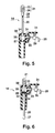
- the antenna device When the antenna assembly 14 is completely pulled out to the extended position as shown in Fig. 5, the first electrical feeder 27 of the whip antenna 20 enters the through hole 34 so that the first electrical feeder 27 is held by the spring member 35. A high-frequency signal is fed to the whip antenna 20 from the high-frequency signal source 25 through the first electrical feeder 27, the shaft 32, and the matching circuit 26. The whip antenna 20 protruding from the housing 15 irradiates radio waves. The insulator 22 serves to prevent the helical antenna 21 from receiving a high-frequency signal.
- the second electrical feeder 28 of the helical antenna 21 is held by the spring member 35.
- a high-frequency signal is fed to the helical antenna 21 from the high-frequency signal source 25 through the second electrical feeder 28, the shaft 32, and the matching circuit 26.
- the helical antenna 21 protruding from the housing 15 irradiates radio waves.
- the insulator 22 likewise serves to prevent the whip antenna 20 from receiving a high-frequency signal.
- the first embodiment allows the helical antenna 21 to efficiently transmit and/or receive a signal having electrical length of a half wavelength, even when the whip antenna 20 is contained in the housing 15.
- the whip antenna 20 does not receive high-frequency signals in the storage position, so that radio waves are not irradiated from the whip antenna 20 within the housing 15.
- Electronic parts within the housing 15 operate reliably.
- Placing the portable information terminal on a desk or the like may facilitate an input operation to the LCD 13 on the front surface of the portable information terminal 10.
- Raising the whip antenna 20 allows the antenna's polarization plane to match'that of radio waves from a base station, thereby achieving a high antenna gain.
- the first embodiment allows the antenna assembly 14 to rotate in a plane inclined by 45 degrees from the X-Y axes reference plane PL as shown in Fig. 3, input operations are not hindered, as may be caused by excessive approach of the antenna assembly 14 to the portable information terminal 10.
- the electrical length of the whip and helical antennas 20, 21 may be set at a quarter, instead of a half, wavelength.
- the electrical length of a quarter wavelength allows an impedance of the antenna device to approach 50 ohms, which allows omission of the matching circuit 26.
- the irradiation patterns of Fig. 9 are illustrated by simulation of the moment method using the wire grid model as shown in Fig. 10. It is apparent that a larger electrical length improves directivity in the horizontal direction.
- the electrical length of a whip antenna may be set at a half wavelength for emphasizing a directivity in the horizontal direction, while being set at a quarter wavelength for omitting a matching circuit. Larger electrical length, over a half wavelength, further allows improved directivity in the horizontal direction.
- Fig. 11 illustrates an antenna device according to a second embodiment of the present invention.
- the second embodiment is characterized in that the spring member 35 holds both the whip and helical antennas 20, 21 when the whip antenna 20 assumes the storage position.
- the whip and helical antennas 20, 21 both receive a common external force even when the rotator 30 accidentally rotates, so that stress is not concentrated on the insulator 22, thereby protecting a relatively weak connection between the whip and helical antennas 20, 21.
- the strength of the antenna assembly 14 can be enhanced accordingly.
- a constant diameter for the whip antenna 20, the insulator 22, and the second electrical feeder 28 as shown in Fig. 11 enables the spring member 35 to simultaneously hold the whip and helical antennas 20, 21.
- the same reference numerals are attached to elements having the same function as those of the first embodiment.
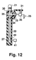
- Fig. 12 illustrates an antenna device according to the third embodiment of the present invention.
- the third embodiment is characterized in that the whip and helical antennas 20, 21 are electrically connected to each other.
- the first electrical feeder 27 of the whip antenna 20 is electrically connected to an impedance control circuit 41 through a metallic contact spring 40 when the antenna assembly 14 assumes the storage position.
- the same reference numerals are attached to elements having the same function as those of the first and second embodiments.
- the third embodiment allows the whip and helical antennas 20, 21 to receive a high-frequency signal through the first electrical feeder 27, the spring member 35, the shaft 32, and the matching circuit 26 when the antenna assembly 14 assumes the extended position.
- the matching circuit 26 has a constant which is set to match a combined impedance of the whip and helical antennas 20, 21.
- the whip and helical antennas 20, 21 When the antenna assembly 14 is in the storage position, the whip and helical antennas 20, 21 receive a high-frequency signal through the second feeder 28, the spring member 35, the shaft 32, and the matching circuit 26. Contact of the first electrical feeder 27 with the contact spring 40 enables the impedance control circuit 41 to match only the impedance of the helical antenna 21. Accordingly, irradiation efficiency cannot be reduced. Further, a connection between the whip and helical antennas 20, 21 can be strengthened or enhanced in the antenna assembly 14 due to direct connection between the whip and helical antennas 20, 21.
- Fig. 13 illustrates an antenna device according to a fourth embodiment.
- the fourth embodiment is characterized in that the antenna assembly 14 can rotate within a plane perpendicular to the X-Y axes reference plane PL of the portable information terminal 10 at the extended position.
- antenna efficiency can further be improved with respect to vertical polarization.
- the antenna assembly 14 can rotate in a range of 180 degrees as shown in Figs. 15 and 16, so that the antenna device can be freely positioned.
- the identical reference numerals are attached to the elements having the same function as those in the previous embodiments.
- the previous embodiments generally employs an antenna assembly 14 comprising a whip antenna 20 as a first antenna and a helical antenna 21 as a second antenna.
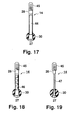
- a planar antenna 44 and a meander line antenna 45 can be employed as shown in Fig. 17 in place of the respective whip and helical antennas.
- a meander line antenna 46 may be combined in place of the planar antenna 44, as shown in Fig. 18, and a helical antenna 47 may be combined in place of the planar antenna as shown in Fig. 19.
- the meander line antennas 45, 46 comprise a meander line wire formed on or embedded in a non-conductive panel member.
- the helical antenna 47 comprises a wire spirally wound around a non-conductive pole member.
- planar antenna 44 or the meander line antennas 45, 46 enables an antenna assembly 14 to be reduced in thickness. Employment of the meander line antennas 45, 46 and the helical antenna 47 enables the reduction in height of the antenna assembly 14. Further, since the planar antenna 44 and a plate member of the meander line antennas 45, 46 are arranged along a plane on which the antenna assembly 14 moves, they have strength along such a plane so that rotating force applied to the antenna assembly 14 is smoothly transmitted to the rotator 30. In Figs. 17 to 19, the first antenna likewise receives a signal through the first electrical feeder 27 while the second antenna likewise receives a signal through the second electrical feeder 28.
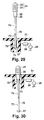
- Fig. 20 illustrates an antenna device according to a fifth embodiment of the present invention.
- the fifth embodiment is characterized in that the antenna device further comprises a withdrawal prevention piece for preventing the first antenna from withdrawing from the extended position when the first antenna rotates relative to the housing.
- the identical reference numerals are attached to the elements having the same function as those in the previous embodiments.
- the withdrawal prevention piece 50 is integrally formed in the housing wall 31 so as to include a prevention surface 51 of a shape corresponding to the peripheral shape of the rotator 30.
- the antenna assembly 14 can displace between the extended position and the storage position at a reference position of the rotator 30 as shown in Fig. 20. When the antenna assembly 14 is pulled out in the withdrawal direction X1 until it is mostly removed from the storage hole 52 of the housing wall 31, the rotator 30 is brought into a rotatable state.
- the prevention surface 51 is opposed to the exit of the through hole 34 of the rotator 30. It is thus possible to prevent the first electrical feeder 27 of the whip antenna 20 from being completely removed out of the rotator 30, whereby electrical connection would be disconnected.
- a click mechanism 53 may be provided between the withdrawal prevention piece 50 and the rotator 30 for temporarily holding the rotator 30.
- the click mechanism 53 comprises a guide slot 54 carved on the periphery of the rotator 30, and a ball 55 provided to the withdrawal prevention piece 50 for moving along the guide slot 54, as shown in Fig. 22.
- the ball 55 fits into a first recess 56 so that the rotator 30 is held at the reference position by the spring 57 biasing the ball 55.
- the ball 55 enters the guide slot 54 against the biasing force from the spring 57 so as to move along the guide slot 54.
- the rotator 30 reaches a fixed position as shown in Fig. 21, the ball 55 fits into a second recess 58 so that the rotator 30 is held at the position by the biasing force from the spring 57.
- the antenna assembly 14 is prevented from moving when it assumes certain positions.
- the withdrawal prevention piece 50 may be formed separately from the housing wall 31.
- the withdrawal prevention piece 50 projects from a planar receiving member 60 which receives the bottom of the rotator 30.
- the receiving member 60 is disposed around the shaft 32, the receiving member 60 is prevented from rotating about the shaft 32 by a rotation blocking mechanism 61 comprising a recess and a projection.
- the rotator 30 includes a notch 62 for receiving the withdrawal prevention piece 50 in the extent the withdrawal displaces. The movement of the rotator 30 is thus not hindered by the withdrawal prevention piece 50.
- the contact of the withdrawal prevention piece 50 with opposite end surfaces of the notch 62 defines an extent of rotation of the rotator 30.
- the identical reference numerals are attached to elements having the same function as those shown in Figs. 20 to 22.
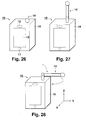
- Fig. 26 illustrates a portable information terminal 10 employing an antenna device according to a sixth embodiment of the present invention.
- the antenna assembly 14 of the portable information device 10 operates at a storage position where the antenna assembly 14 is contained within the housing 15 as shown in Fig. 26, and an extended position where the antenna assembly 14 is pulled out of the housing 15 as shown in Fig. 27.
- the antenna assembly 14 at the extended position as shown in Fig. 28 can bend and/or rotate so as to cause the tip thereof to trace a semi-sphere.
- the identical reference numerals are attached to elements having the same function as those in the foregoing embodiments.
- the antenna assembly 14 comprises a whip antenna 70 having an electrical length of a half wavelength as a first antenna made from metallic material such as stainless, and a helical antenna 21 attached to the tip of the aforementioned whip antenna 20 (a second antenna).
- the whip antenna 70 is held at its base end by an elastic force of a spring member 72 (see Fig. 32) embedded in a storage hole 71 of the housing wall 31.
- the whip antenna 70 receives a high-frequency signal from the high-frequency signal source 25 through the first electrical feeder 27.
- the helical antenna 21 is held at its base end by the spring member 72.
- the helical antenna 21 receives a high-frequency signal from the high-frequency signal source 25 through the spring member 72.
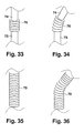
- the whip antenna 70 comprises a support piece 73 supported by the housing wall 31 at the extended position, and a tip piece 74 connected to the support piece 73 for swinging movement for supporting the helical antenna 21.
- the support piece 73 and the tip piece 74 are connected to each other with an axis 75, so that the tip piece 74 can swing in a range of 180 degrees.
- the antenna assembly 14 can match to a polarization plane of radio wave from a base station without using a rotator required in the preceding embodiments, which allows a simplified structure and reduced volume.
- a flexible arm 76 can be employed in place of the axis 75 between the support piece 73 and the tip piece 74 as shown in Figs. 33 and 34. Since a flexible arm has sufficient significant elasticity to resist a strong impact, the whip antenna 70 is unlikely to be broken. Additionally, the whip antenna 70 can be smoothly rotated and bent, leading to facilitated handling. If the whip antenna 70 is entirely comprised of a flexible arm, as shown in Figs. 35 and 36, the whip antenna 70 can be bent to a desired position.
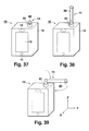
- Fig. 37 illustrates a portable information terminal 10 employing an antenna device according to a seventh embodiment of the present invention.
- the antenna assembly 14 of the portable information terminal 10 comprises a whip antenna 80 as a first antenna capable of moving between a storage position where the whip antenna 80 is contained within the housing 15, and an extended position where the antenna 80 is pulled out of the housing 15 for receiving and/or transmitting a signal; and a helical antenna 81 as a second antenna attached to an external surface of the housing 15 for surrounding the whip antenna 80.
- the helical antenna 81 transmits and receives a signal when the whip antenna 80 assumes the storage position.
- the antenna assembly 14 can rotate and/or bend at the extended position, similar to the preceding embodiments, so as to cause the tip of the antenna assembly 14 to trace a semi-sphere as shown in Fig. 39.
- the helical antenna 81 is fixed to the housing 15, the weight of the tip or the volume of the whip antenna 81 can be reduced, thereby enhancing mechanical strength of the antenna assembly 14.
- the identical reference numerals are attached to the elements having the same function as those in the foregoing embodiments.
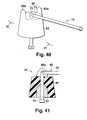
- the helical antenna 81 fixed to the equipment 15 can be covered by an elastic member 82 such as rubber or soft resin as shown in Fig. 40.
- the elastic member 82 may reduce any external force applied to the helical antenna 81.
- a protection piece 82a may be provided to the elastic member 82 so that the connection between the support piece 73 and the tip piece 74 is protected from impact should the portable information terminal 10 be dropped.
- a signal may be supplied to both the whip and helical antennas 80, 81 at both the extended and storage positions as shown in Figs. 42A and 42B.
- the helical antenna 81 receives a high-frequency signal directly from the high-frequency signal source 25 while the whip antenna 80 receives a high-frequency signal through the spring member 35 and the first electrical feeder 27.
- the antenna assembly 14 assumes the storage position, as shown in Fig. 42B, the helical antenna 81 receives a high-frequency signal directly from the high-frequency signal source 25 while the whip antenna 80 receives a high-frequency signal through the spring member 35 and the second electrical feeder 85.
- the adjustment of length of the whip antenna 80 protruding from the housing wall 31 at the extended position of the antenna assembly 14 enables exclusion of the effect from a fed signal to the whip antenna 80.
- the adjustment of length of the whip antenna 80 within the housing 15 at the storage position of the antenna assembly 14 enables exclusion of the effect from a fed signal to the whip antenna 80, thereby leading to a superior irradiation pattern.
- a signal may be supplied to both the whip and helical antennas 80, 81 at the extended position of the antenna assembly 14 while a signal may be supplied only to the helical antenna 81 at the storage position as shown in Fig. 43A and 43B.
- the whip antenna 80 is provided with an insulator 86.
- the helical antenna 81 receives a high-frequency signal directly from the high-frequency signal source 25 while the whip antenna 80 receives a high-frequency signal through the spring member 35 and the first electrical feeder 27.
- the antenna assembly 14 assumes the storage position, as shown in Fig.
- the helical antenna 81 receives a high-frequency signal directly from the high-frequency signal source 25.
- the whip antenna 80 does not receive a high-frequency signal since the spring member 35 contacts against the insulator 86.
- the helical antenna 81 achieves a superior irradiation pattern at the storage position without the effect of the whip antenna 80.
- the antenna assembly 14 may be longer by the amount of length of the insulator 86 as compared with the example shown in Figs. 42A and 42B.
- the whip antenna 80 may receive a signal without the first and second electrical feeder 27, 85 in this seventh embodiment since the whip antenna 80 is surrounded by the helical antenna 81 at the storage position of the antenna assembly 14. Specifically, when the helical antenna 81 irradiates radio waves in the condition shown in Figs. 42B and 43B, an electrical current is induced in the whip antenna 80 so that both the whip and helical antennas 80, 81 irradiate radio waves. Any operational difference cannot be observed even when the above method of supplying a signal to the whip antenna 80 is employed.
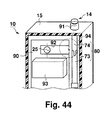
- Fig. 44 illustrates a portable information terminal 10 employing an antenna device according to an eighth embodiment of the present invention.
- the eighth embodiment is characterized in that the antenna device comprises a first antenna capable of moving between a storage position and an extended position, and a second antenna disposed within the housing for magnetoelectrically coupling with the first antenna.
- the identical reference numerals are attached to elements having the same functions as those in the previous embodiments.
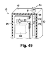
- the antenna device of the eighth embodiment comprises a whip antenna 80 as the first antenna and a notch antenna 90 as the second antenna.
- the tip of the whip antenna 80 at the storage position protrudes from a surface of the housing 15 by means of an elastic piece 91 serving as a support means attached to a surface of the housing 15.
- the notch antenna 90 comprises an opening 92 of an antenna height or opening width h opposed to the whip antenna 80 at both the storage and an extended positions as shown in Fig. 44.
- the opening 92 is positioned offset from a metallic member such as a shield metallic box 93 for containing an inner circuit substrate.
- a high-frequency signal is supplied to the notch antenna 90 from the high-frequency signal source 25 at the storage position shown in Fig. 44.
- the notch antenna forms an electromagnetic connection 94 with the whip antenna 80 in the vicinity of the opening 92.
- an electrical current is induced in the whip antenna 80, so that the whip antenna 80 irradiates radio waves.
- Sufficient antenna height of the notch antenna 90 allows a sufficient irradiation efficiency even when the whip antenna 80 is contained within the housing 15.
- the notch antenna 90 is usually matched to an impedance of 50 ohms so that a matching circuit can be omitted. A slight difference between impedance of the notch and whip antenna 90, 80 can be adjusted by controlling the lengths of these notch and whip antennas.
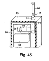
- a high-frequency signal is supplied to the whip antenna 80 through the electromagnetic connection 94 of the notch antenna 90 at the extended position shown in Fig. 45 similar to the previous description.
- the whip antenna 80 comprising the support and tip pieces 73, 74 can likewise rotate and/or bend at the extended position as shown in Fig. 46.
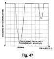
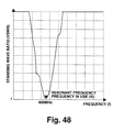
- Figs. 47 and 48 illustrate the result of an experiment for the antenna device according to the eighth embodiment. It can be observed that there is less difference between resonance points of the antenna device at the storage position (Fig. 47) and the extended position (Fig. 48) so that a common matching circuit can be employed. Specifically, a matched impedance for the notch antenna 90 allows omission of a matching circuit. It has been proved that the whip antenna 80 may achieve a sufficient irradiation with the tip protruding from the surface of the housing 15 by an amount of 20 to 25mm.
- the eighth embodiment allows a simplified structure with omission of a matching circuit, a helical antenna and a rotator, thereby contributing to reduction of cost.
- a signal is supplied to the whip antenna 80 by a non-contact connection such as an electromagnetic connection so that the structure of the whip antenna can be simplified, thereby contributing to reduction of cost.
- the notch antenna 90 can be disposed within the housing 15, so that mobility of the portable information terminal 10 can be improved and design variation can be widened.
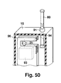
- the antenna device of the eighth embodiment may employ a slot antenna 96 in place of the aforementioned notch antenna 90 as shown in Figs. 49 to 51.
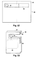
- the slot antenna 96 comprises a conductive plate 97 having a slot 98 of height h as shown in Fig. 52.
- the conducive plate 97 may be folded or separated into two pieces as shown in Fig. 53 with respect to the center line. In the latter case, conductive lines 99 may be formed between the opposed pieces. In either cases, the conductive plate 97 only occupies a half of the volume as compared with the original one.
- the shield metallic box 93 may be disposed between the opposed pieces 97 for containing an inner circuit substrate. Since the slot antenna generally have a frequency band wider than the notch antenna so that it is easy to match an impedance of the slot antenna.
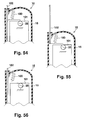
- Figs. 54 to 56 illustrate a portable information terminal 10 employing an antenna device according to a ninth embodiment of the present invention.
- the ninth embodiment is characterized in that a helical antenna as a second antenna is disposed within the housing 15 of the portable information terminal 10.
- the helical antenna 100 is arranged in a space between the metallic inner circuit substrate 101 and the inner surface of the housing 15. This structure enables a simplified structure of the helical antenna 100 since the helical antenna 100 is protected within the housing 15. Further, the helical antenna 100 can be hidden in the inner space so that the portable information terminal 10 achieves a simplified appearance.
- the meander line antenna 102 as a first antenna receives a signal from the high-frequency signal source 25 at the extended position as shown in Fig. 55 or at the storage position shown in Fig. 54.
- the meander line antenna 102 may not receive a signal at the storage position as shown in Fig. 56.
- the identical reference numerals are attached to elements having the same functions as those in the previous embodiments.
- the ninth embodiment may employ in place of the contained helical antenna 100 a circuit antenna 103 comprising a capacitance and a reactance.
- the circuit antenna 103 comprises a reactance element 104 connected to the high-frequency signal source 25.
- the rotator 105 causes an electromagnetic connection so as to induce an electrical current in the whip antenna 106 which is not electrically connected to the rotator 105.
- a capacitance is established between the metallic rotator 105 and the tip of the whip antenna 106 so that the whip antenna 106 allows LC resonance to irradiate radio waves.
- An electromagnetical connection likewise allows the whip antenna 106 to irradiate radio waves at the extended position as shown in Fig. 58. Since the reactance element 104 can be employed as a second antenna in place of the helical or meander line antenna, it is possible to reduce the cost of the antenna device.
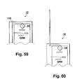
- Figs. 59 and 60 illustrate a portable information terminal 10 employing an antenna device according to a tenth embodiment of the present invention.
- the tenth embodiment is characterized in that attenuation in irradiation efficiency of the first antenna can be prevented by matching to an impedance of the first antenna at the storage position.
- the antenna device comprises an impedance control circuit 111 for contacting the whip antenna 110 as the first antenna at the storage position so as to establish a matched impedance.
- the impedance control circuit 111 shorts the whip antenna to the ground GRN.
Landscapes
- Engineering & Computer Science (AREA)
- Computer Networks & Wireless Communication (AREA)
- Support Of Aerials (AREA)
- Transceivers (AREA)
- Waveguide Aerials (AREA)
- Details Of Aerials (AREA)
- Telephone Set Structure (AREA)
Applications Claiming Priority (5)
| Application Number | Priority Date | Filing Date | Title |
|---|---|---|---|
| JP24444695 | 1995-09-22 | ||
| JP24444695 | 1995-09-22 | ||
| JP21994796A JP3674172B2 (ja) | 1995-09-22 | 1996-08-21 | アンテナ装置 |
| JP21994796 | 1996-08-21 | ||
| EP96115105A EP0764998B1 (fr) | 1995-09-22 | 1996-09-20 | Antenne |
Related Parent Applications (1)
| Application Number | Title | Priority Date | Filing Date |
|---|---|---|---|
| EP96115105A Division EP0764998B1 (fr) | 1995-09-22 | 1996-09-20 | Antenne |
Publications (2)
| Publication Number | Publication Date |
|---|---|
| EP1069641A2 true EP1069641A2 (fr) | 2001-01-17 |
| EP1069641A3 EP1069641A3 (fr) | 2003-04-16 |
Family
ID=26523423
Family Applications (4)
| Application Number | Title | Priority Date | Filing Date |
|---|---|---|---|
| EP00117623A Withdrawn EP1069640A3 (fr) | 1995-09-22 | 1996-09-20 | Dispositif d'antenne |
| EP00117624A Withdrawn EP1069641A3 (fr) | 1995-09-22 | 1996-09-20 | Dispositif d'antenne |
| EP00117622A Withdrawn EP1075039A3 (fr) | 1995-09-22 | 1996-09-20 | Dispositif d'antenne |
| EP96115105A Expired - Lifetime EP0764998B1 (fr) | 1995-09-22 | 1996-09-20 | Antenne |
Family Applications Before (1)
| Application Number | Title | Priority Date | Filing Date |
|---|---|---|---|
| EP00117623A Withdrawn EP1069640A3 (fr) | 1995-09-22 | 1996-09-20 | Dispositif d'antenne |
Family Applications After (2)
| Application Number | Title | Priority Date | Filing Date |
|---|---|---|---|
| EP00117622A Withdrawn EP1075039A3 (fr) | 1995-09-22 | 1996-09-20 | Dispositif d'antenne |
| EP96115105A Expired - Lifetime EP0764998B1 (fr) | 1995-09-22 | 1996-09-20 | Antenne |
Country Status (7)
| Country | Link |
|---|---|
| US (1) | US5949377A (fr) |
| EP (4) | EP1069640A3 (fr) |
| JP (1) | JP3674172B2 (fr) |
| CN (1) | CN1073295C (fr) |
| CA (1) | CA2185863C (fr) |
| DE (1) | DE69622337T2 (fr) |
| IL (1) | IL119278A (fr) |
Cited By (1)
| Publication number | Priority date | Publication date | Assignee | Title |
|---|---|---|---|---|
| WO2007100380A1 (fr) * | 2006-02-28 | 2007-09-07 | Sony Ericsson Mobile Communications Ab | configuration d'un système d'antenne pour téléphones portables |
Families Citing this family (26)
| Publication number | Priority date | Publication date | Assignee | Title |
|---|---|---|---|---|
| US6198448B1 (en) * | 1997-07-29 | 2001-03-06 | Tokin Corporation | Lightweight antenna assembly comprising a whip antenna and a helical antenna mounted on a top end of the whip antenna |
| JPH11298219A (ja) * | 1998-04-10 | 1999-10-29 | Tokin Corp | アンテナとそれを用いた携帯用無線機 |
| JP2000049519A (ja) * | 1998-05-27 | 2000-02-18 | Ace Technol Co Ltd | 携帯通信端末器用アンテナ装置 |
| SE9802772D0 (sv) * | 1998-08-19 | 1998-08-19 | Allgon Ab | Antenna device comprising sliding connector means |
| CN1199315C (zh) * | 1999-12-09 | 2005-04-27 | 三菱电机株式会社 | 天线装置及其移动无线装置 |
| CN1203573C (zh) * | 2000-01-14 | 2005-05-25 | 三菱电机株式会社 | 便携无线机的天线结构 |
| US6556171B2 (en) * | 2001-02-06 | 2003-04-29 | Motorola, Inc. | Extendible antenna with articulating hinge |
| JP3912754B2 (ja) | 2003-01-08 | 2007-05-09 | ソニー・エリクソン・モバイルコミュニケーションズ株式会社 | 無線装置 |
| JP2005176302A (ja) | 2003-09-26 | 2005-06-30 | Nec Access Technica Ltd | 携帯端末のアンテナ装置および放送波を受信可能な無線機 |
| WO2006027895A1 (fr) * | 2004-09-10 | 2006-03-16 | Murata Manufacturing Co., Ltd. | Structure d’alimentation d’antenne |
| JP2005102286A (ja) * | 2004-11-08 | 2005-04-14 | Toshiba Corp | 電子機器 |
| US20060202894A1 (en) * | 2005-03-09 | 2006-09-14 | Shary Nassimi | Conductive Plastic Antenna |
| US7286096B2 (en) * | 2005-03-28 | 2007-10-23 | Radiolink Networks, Inc. | Aligned duplex antennae with high isolation |
| KR101076567B1 (ko) * | 2006-04-21 | 2011-10-24 | 엘지전자 주식회사 | 안테나 및 이를 갖는 휴대 단말기 |
| JP4841398B2 (ja) * | 2006-10-27 | 2011-12-21 | 京セラ株式会社 | ループアンテナ、アンテナ基板、アンテナ一体モジュールおよび通信機器 |
| US20100289713A1 (en) * | 2007-05-16 | 2010-11-18 | Toru Taura | Slot antenna |
| US7548209B2 (en) * | 2007-09-14 | 2009-06-16 | Giga-Byte Communications Inc. | Portable wireless communication apparatus |
| US7656355B2 (en) * | 2007-09-14 | 2010-02-02 | Giga-Byte Communications Inc. | Stylus arranged with antenna and portable wireless communication device having the same |
| JP5105164B2 (ja) * | 2007-12-10 | 2012-12-19 | 日本電気株式会社 | アンテナ構造及び携帯端末 |
| JP4496268B1 (ja) | 2008-12-25 | 2010-07-07 | 株式会社東芝 | 電子機器 |
| JP5482171B2 (ja) * | 2009-12-11 | 2014-04-23 | 富士通株式会社 | アンテナ装置、及び無線端末装置 |
| JP5651974B2 (ja) * | 2010-03-26 | 2015-01-14 | 富士通株式会社 | 携帯端末装置 |
| EP2750249B1 (fr) * | 2011-08-24 | 2019-05-22 | NEC Corporation | Antenne et dispositif électronique |
| JP2014183352A (ja) * | 2013-03-18 | 2014-09-29 | Eibitsuto:Kk | 無線機器のアンテナ構造 |
| USD772206S1 (en) * | 2014-08-04 | 2016-11-22 | Enersphere Communications Llc | Communications pole with antenna-luminary assembly |
| CN106025506A (zh) * | 2016-06-24 | 2016-10-12 | 芜湖辉灿电子科技有限公司 | 降低辐射伤害的手机天线 |
Family Cites Families (17)
| Publication number | Priority date | Publication date | Assignee | Title |
|---|---|---|---|---|
| DE1441739A1 (de) * | 1964-12-23 | 1969-03-13 | Karst Robert Fa | Versenkbar und schwenkbar ausgebildete Teleskopantenne |
| US3522608A (en) * | 1969-02-19 | 1970-08-04 | Gen Electric | Telescoping vhf-uhf antenna for a television receiver |
| US3798651A (en) * | 1972-08-23 | 1974-03-19 | R Lehman | Antenna mounting fixture |
| ES443806A1 (es) * | 1974-12-25 | 1977-08-16 | Matsushita Electric Industrial Co Ltd | Perfeccionamientos introducidos en un aparato de antena paraun receptor de television o similar. |
| US4121218A (en) * | 1977-08-03 | 1978-10-17 | Motorola, Inc. | Adjustable antenna arrangement for a portable radio |
| JP2554762B2 (ja) * | 1990-02-23 | 1996-11-13 | 株式会社東芝 | アンテナと無線機 |
| GB2253949B (en) * | 1991-03-16 | 1995-08-09 | Antenna Products Ltd | Radio Antennas |
| EP0508299B1 (fr) * | 1991-04-10 | 1996-02-07 | Siemens Aktiengesellschaft | Radio téléphone avec antenne d'appareil |
| JP2703670B2 (ja) * | 1991-04-12 | 1998-01-26 | 三菱電機株式会社 | アンテナ装置 |
| DE69215283T2 (de) * | 1991-07-08 | 1997-03-20 | Nippon Telegraph & Telephone | Ausfahrbares Antennensystem |
| JPH0550816A (ja) * | 1991-08-20 | 1993-03-02 | Sumitomo Wiring Syst Ltd | タイヤ滑り止め装置 |
| JP2520557B2 (ja) * | 1993-02-26 | 1996-07-31 | 日本電気株式会社 | 無線機用アンテナ |
| JP2570087B2 (ja) * | 1993-03-24 | 1997-01-08 | 日本電気株式会社 | 携帯型無線機 |
| JPH0786819A (ja) * | 1993-09-09 | 1995-03-31 | Mitsubishi Electric Corp | アンテナ装置 |
| US5617105A (en) * | 1993-09-29 | 1997-04-01 | Ntt Mobile Communications Network, Inc. | Antenna equipment |
| JP2596374B2 (ja) * | 1994-05-30 | 1997-04-02 | 日本電気株式会社 | 携帯無線機 |
| US5644320A (en) * | 1994-06-30 | 1997-07-01 | Compaq Computer Corporation | Antenna system for a notebook computer |
-
1996
- 1996-08-21 JP JP21994796A patent/JP3674172B2/ja not_active Expired - Fee Related
- 1996-09-18 CA CA002185863A patent/CA2185863C/fr not_active Expired - Fee Related
- 1996-09-19 IL IL11927896A patent/IL119278A/xx not_active IP Right Cessation
- 1996-09-20 DE DE69622337T patent/DE69622337T2/de not_active Expired - Fee Related
- 1996-09-20 EP EP00117623A patent/EP1069640A3/fr not_active Withdrawn
- 1996-09-20 EP EP00117624A patent/EP1069641A3/fr not_active Withdrawn
- 1996-09-20 EP EP00117622A patent/EP1075039A3/fr not_active Withdrawn
- 1996-09-20 EP EP96115105A patent/EP0764998B1/fr not_active Expired - Lifetime
- 1996-09-20 US US08/718,265 patent/US5949377A/en not_active Expired - Fee Related
- 1996-09-21 CN CN96114420A patent/CN1073295C/zh not_active Expired - Fee Related
Cited By (2)
| Publication number | Priority date | Publication date | Assignee | Title |
|---|---|---|---|---|
| WO2007100380A1 (fr) * | 2006-02-28 | 2007-09-07 | Sony Ericsson Mobile Communications Ab | configuration d'un système d'antenne pour téléphones portables |
| US7342545B2 (en) | 2006-02-28 | 2008-03-11 | Sony Ericsson Mobile Communications Ab | Antenna system configuration for mobile phones |
Also Published As
| Publication number | Publication date |
|---|---|
| JP3674172B2 (ja) | 2005-07-20 |
| IL119278A (en) | 2000-12-06 |
| JPH09148824A (ja) | 1997-06-06 |
| EP1075039A2 (fr) | 2001-02-07 |
| DE69622337D1 (de) | 2002-08-22 |
| EP0764998A1 (fr) | 1997-03-26 |
| CN1157493A (zh) | 1997-08-20 |
| EP1069640A2 (fr) | 2001-01-17 |
| CA2185863C (fr) | 2000-05-02 |
| EP1069641A3 (fr) | 2003-04-16 |
| IL119278A0 (en) | 1996-12-05 |
| US5949377A (en) | 1999-09-07 |
| CA2185863A1 (fr) | 1997-03-23 |
| EP1075039A3 (fr) | 2003-04-16 |
| DE69622337T2 (de) | 2003-03-20 |
| EP1069640A3 (fr) | 2003-05-28 |
| CN1073295C (zh) | 2001-10-17 |
| EP0764998B1 (fr) | 2002-07-17 |
Similar Documents
| Publication | Publication Date | Title |
|---|---|---|
| US5949377A (en) | Retractable, extendable and rotatable dual antenna system | |
| US6765846B2 (en) | Antenna apparatus and wristwatch radio communication device using same | |
| US6995718B2 (en) | Computer with an embedded antenna | |
| US6933897B2 (en) | Mobile communications antenna and transceiving apparatus | |
| US7225003B2 (en) | Mobile terminal including first and second housings and an antenna | |
| JP3955041B2 (ja) | 携帯電話機 | |
| CN101288289B (zh) | 携带式无线电设备 | |
| JP2002151923A (ja) | 携帯端末機 | |
| JPH06188805A (ja) | 無線装置 | |
| KR100504803B1 (ko) | 휴대용 단말기의 전파송수신장치 | |
| TW413964B (en) | Radio-set | |
| US5909653A (en) | Portable radio device | |
| US5929814A (en) | Antenna assembly and communications device | |
| KR20010006783A (ko) | 안테나 및 휴대단말장치 | |
| US6577279B1 (en) | Antenna structure of portable radio | |
| JP4318605B2 (ja) | 折り畳み式携帯電話機 | |
| JP2003037411A (ja) | 携帯用無線機 | |
| JPWO2002037602A1 (ja) | アンテナ装置および携帯機器 | |
| JPH1155143A (ja) | 無線通信装置 | |
| JP2000036706A (ja) | 携帯型無線通信装置およびヘリカルアンテナ装置 | |
| JPH04110007U (ja) | 携帯用電話装置 | |
| JP2000223920A (ja) | 無線通信装置のアンテナ構造 | |
| KR20050095671A (ko) | 다각형 폴디드 모노폴 인테나 |
Legal Events
| Date | Code | Title | Description |
|---|---|---|---|
| PUAI | Public reference made under article 153(3) epc to a published international application that has entered the european phase |
Free format text: ORIGINAL CODE: 0009012 |
|
| 17P | Request for examination filed |
Effective date: 20000816 |
|
| AC | Divisional application: reference to earlier application |
Ref document number: 764998 Country of ref document: EP |
|
| AK | Designated contracting states |
Kind code of ref document: A2 Designated state(s): DE FR GB SE |
|
| PUAL | Search report despatched |
Free format text: ORIGINAL CODE: 0009013 |
|
| RIC1 | Information provided on ipc code assigned before grant |
Ipc: 7H 01Q 1/10 B Ipc: 7H 01Q 1/24 B Ipc: 7H 01Q 1/08 A |
|
| AK | Designated contracting states |
Designated state(s): DE FR GB SE |
|
| AKX | Designation fees paid |
Designated state(s): DE FR GB SE |
|
| STAA | Information on the status of an ep patent application or granted ep patent |
Free format text: STATUS: THE APPLICATION IS DEEMED TO BE WITHDRAWN |
|
| 18D | Application deemed to be withdrawn |
Effective date: 20031017 |