EP1069342B1 - Riemen für stufenlos regelbares Getriebe - Google Patents
Riemen für stufenlos regelbares Getriebe Download PDFInfo
- Publication number
- EP1069342B1 EP1069342B1 EP99945691A EP99945691A EP1069342B1 EP 1069342 B1 EP1069342 B1 EP 1069342B1 EP 99945691 A EP99945691 A EP 99945691A EP 99945691 A EP99945691 A EP 99945691A EP 1069342 B1 EP1069342 B1 EP 1069342B1
- Authority
- EP
- European Patent Office
- Prior art keywords
- metal
- belt
- metal elements
- pulley
- contact surfaces
- Prior art date
- Legal status (The legal status is an assumption and is not a legal conclusion. Google has not performed a legal analysis and makes no representation as to the accuracy of the status listed.)
- Expired - Lifetime
Links
- 230000005540 biological transmission Effects 0.000 title claims description 21
- 229910052751 metal Inorganic materials 0.000 claims abstract description 143
- 239000002184 metal Substances 0.000 claims abstract description 85
- 230000000712 assembly Effects 0.000 claims description 9
- 238000000429 assembly Methods 0.000 claims description 9
- 230000002265 prevention Effects 0.000 abstract description 2
- 238000004804 winding Methods 0.000 abstract 1
- 230000003247 decreasing effect Effects 0.000 description 4
- 230000002159 abnormal effect Effects 0.000 description 2
- 238000010521 absorption reaction Methods 0.000 description 2
- 238000003754 machining Methods 0.000 description 2
- 238000005096 rolling process Methods 0.000 description 2
- 230000015572 biosynthetic process Effects 0.000 description 1
- 238000006243 chemical reaction Methods 0.000 description 1
- 230000006835 compression Effects 0.000 description 1
- 238000007906 compression Methods 0.000 description 1
- 230000001276 controlling effect Effects 0.000 description 1
- 230000000694 effects Effects 0.000 description 1
- 230000002708 enhancing effect Effects 0.000 description 1
- 239000000463 material Substances 0.000 description 1
- 238000012986 modification Methods 0.000 description 1
- 230000004048 modification Effects 0.000 description 1
- 230000002093 peripheral effect Effects 0.000 description 1
- 238000004080 punching Methods 0.000 description 1
- 230000001105 regulatory effect Effects 0.000 description 1
Images


Classifications
-
- F—MECHANICAL ENGINEERING; LIGHTING; HEATING; WEAPONS; BLASTING
- F16—ENGINEERING ELEMENTS AND UNITS; GENERAL MEASURES FOR PRODUCING AND MAINTAINING EFFECTIVE FUNCTIONING OF MACHINES OR INSTALLATIONS; THERMAL INSULATION IN GENERAL
- F16G—BELTS, CABLES, OR ROPES, PREDOMINANTLY USED FOR DRIVING PURPOSES; CHAINS; FITTINGS PREDOMINANTLY USED THEREFOR
- F16G5/00—V-belts, i.e. belts of tapered cross-section
- F16G5/16—V-belts, i.e. belts of tapered cross-section consisting of several parts
Definitions
- the present invention relates to a belt for a continuously variable transmission, including a large number of metal elements supported on metal ring assemblies each of which is comprised of a plurality of endless metal rings laminated one on another, and particularly, to a metal element structure thereof.
- a stationary pulley half 04 of the drive pulley 01 and a stationary pulley half 05 of the driven pulley 02 are disposed at diagonal positions
- a movable pulley half 06 of the drive pulley 01 and a movable pulley half 07 of the driven pulley 02 are disposed at diagonal positions.
- a belt-type continuously variable transmission is conventionally known from Japanese Patent Application Laid-open No. 4-362338 , in which to wind the metal belt 03 around the drive pulley 01 and the driven pulley 02 with the misalignment ⁇ absorbed, at least one of the front and rear contact surfaces of the metal elements 08 constituting the metal belt 03 is formed into an arcuate shape, thereby making a relative yawing possible between the metal elements 08 which are in contact with each other.
- a belt-type continuously variable transmission is disclosed in Japanese Utility Model Application Laid-open No. 63-33046 , in which the thickness of a metal element from its inner periphery to an outer periphery side of the pitch line increases, so that the metal element has a wedge-shaped section.
- the metal belt 03 of the belt-type continuously variable transmission described in Japanese Patent Application Laid-open No. 4-362338 is formed to transmit a driving force by a compressing force applied between the metal elements 08 which are in contact with each other at contact surfaces thereof.
- a conventional metal belt including metal elements 08 of which contact surfaces are formed into an arcuate shape however, the attitude of the metal elements 08 in a yawing direction is unstable and for this reason, there is a possibility that the movement of the metal belt 03 in a zigzag direction may be promoted, whereby the efficient transmission of a power may be impeded.
- the present invention has been accomplished with the above circumstances in view, and it is an object of the present invention to ensure that the absorption of a misalignment between the drive pulley and the driven pulley and the prevention of the zigzag movement of the metal belt are reconciled in the metal belt for the belt-type continuously variable transmission.
- a belt for a continuously variable transmission comprising a large number of metal elements supported on metal ring assemblies each of which is comprised of a plurality of endless metal rings laminated one on another, the belt being wound around a drive pulley and a driven pulley to transmit a driving force between both of the pulleys, wherein each of the metal elements includes a ring slot into which the metal ring assembly is fitted, an element body portion located on a radially inner side of the ring slot, and an element head portion located on a radially outer side of the ring slot, the element body portion and the element head portion each being formed with contact surfaces, at which the metal elements can contact with each other, a lateral width of the contact surface of the element body portion being smaller than a lateral width of the contact surface of the element head portion.
- the adjacent metal elements are brought into contact with each other at least on contact surfaces of the element head portions located on the radially outer side to transmit the driving force.
- the adjacent metal elements can be brought into close contact with each other without yawing by virtue of the contact surfaces of the element head portions having the large lateral width to reliably transmit the driving force.
- the misalignment between the drive pulley and the driven pulley can be absorbed by the lateral sliding movement of the contact surfaces of the element head portions on each other.
- the adjacent metal elements are in contact with each other on the contact surfaces of the element body portions located on the radially inner side, but at this time, the relative yawing movement between the adjacent metal elements is permitted by virtue of the contact surfaces of the element body portions having the small lateral width.
- the inclination of the metal elements in the yawing direction can be corrected, and the metal elements can be wound in a correct attitude around the drive pulley and the driven pulley, thereby avoiding the generation of abnormal wearing of the pulleys and the metal elements.
- the surface pressure on the element body portions which contact with each other over a narrow area is higher than that on the element head portions which contact with each other over a wide area.
- the element body portion is largely distorted, as compared with the element head portion, whereby the sectional shape of the metal element is deformed into a wedge shape.
- the plurality of metal elements are curved radially outwards and connected together in the chord portion of the metal belt and hence, the inner peripheral surfaces of the ring slots of the metal elements are urged radially inwards by the metal ring assemblies, whereby the rolling of the metal elements is prevented.
- the contact surface of the element head portion which is a main contact surface is formed on the element head portion having a relatively simple flat plate shape rather than on the element body portion having a relatively complicated three-dimensional shape, it is convenient for the machining thereof.
- lateral is defined as a direction perpendicular to the rotating plane of the pulley
- radially inner side and “radially outer side” are defined as being with respect to the rotating axis of the pulley.
- a belt for a continuously variable transmission wherein the the metal elements are positioned relative to each other by fitting of a projection and a recess, formed on one and the other of front and rear surfaces thereof, with each other.
- front surface and rear surface of the metal element are defined as front and rear surfaces of the metal element in the direction of movement thereof.
- Figs.1 to 10 show a first embodiment of the present invention, wherein Fig.1 is a skeleton illustration of a power transmitting system of a vehicle having a belt-type continuously variable transmission mounted thereon; Fig.2 is a partial perspective view of a metal belt; Fig.3 is a view taken in the direction or an arrow 3 in Fig.2 ; Fig.4 is a view taken in the direction of an arrow 4 in Fig.2 ; Fig.5 is a sectional view taken along a line 5-5 in Fig.4 ; Fig.6 is a sectional view taken along a line 6-6 in Fig.4 ; Fig.7 is a sectional view taken along a line 7-7 in Fig.4 : Fig.8 is a view for explaining the operation for the absorption of a misalignment; Fig.9 is a view for explaining the operation for deforming a main surface into a wedge shape; and Fig.10 is a view showing metal elements in a
- Figs.11 and 12 show a second embodiment of the present invention, wherein Fig.11 is a sectional view of the metal element, similar to Fig.5 , and Fig.12 is a sectional view of the metal element, likewise similar to Fig.6 .
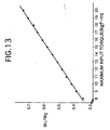
- Fig.13 is a graph showing a limit value of W 1 /W 2 when the maximum input torque is varied.
- Fig. 14 is a view showing a conventional continuously variable transmission.
- Fig.1 shows the skeleton structure of a metal belt-type continuously variable transmission T mounted on an automobile.
- An input shaft 3 is connected to a crankshaft 1 of an engine E through a damper 2 and also connected to a drive shaft 5 of the metal belt-type continuously variable transmission T through a starting clutch 4.
- a drive pulley 6 is mounted on the drive shaft 5 and includes a stationary pulley half 7 secured to the drive shaft 5, and a movable pulley half 8 which is movable toward and away from the stationary pulley half 7.
- the movable pulley half 8 is biased toward the stationary pulley half 7 by a hydraulic pressure applied to an oil chamber 9.
- a driven pulley 11 is mounted on a driven shaft 10 disposed in parallel to the drive shaft 5, and includes a stationary pulley half 12 secured to the driven shaft 10, and a movable pulley half 13 which is movable toward and away from the stationary pulley half 12.
- the movable pulley half 13 is biased toward the stationary pulley half 12 by a hydraulic pressure applied to an oil chamber 14.
- a metal belt 15 comprising a large number of metal elements 32 supported on a pair of left and right metal ring assemblies 31, 31 is wound around the drive pulley 6 and the driven pulley 11 (see Fig.2 ).
- Each of the metal ring assemblies 31 comprises twelve metal rings 33 laminated one on another.
- a forward drive gear 16 and a backward drive gear 17 are rotatably carried on the driven shaft 10 and are capable of being selectively coupled to the driven shaft 10 by a selector 18. Secured to an output shaft 19 disposed in parallel to the driven shaft 10 are a forward driven gear 20 meshed with the forward drive gear 16, and a backward driven gear 22 meshed with the backward drive gear 17 through a backward idle gear 21.
- the rotation of the output shaft 19 is inputted to a differential 25 through a final drive gear 23 and a final driven gear 24 and then transmitted from the differential 25 through left and right axles 26, 26 to driven wheels W, W.
- a driving force from the engine E is transmitted through the crankshaft 1, the damper 2, the input shaft 3, the starting clutch 4, the drive shaft 5, the drive pulley 6, the metal belt 15 and the driven pulley 11 to the driven shaft 10.
- the driving force of the driven shaft 10 is transmitted through the forward drive gear 16 and the forward driven gear 20 to the output shaft 19 to move the vehicle forwards.
- the driving force of the driven shaft 10 is transmitted through the backward drive gear 17, the backward idle gear 21 and the backward driven gear 22 to the output shaft 19 to move the vehicle backwards.
- the shift ratio is continuously regulated by controlling the hydraulic pressures applied to the oil chamber 9 in the drive pulley 6 and the oil chamber 14 in the driven pulley 11 of the metal belt-type continuously variable transmission T by a hydraulic control unit U 2 which is operated by a command from an electronic control unit U 1 . More specifically, if the hydraulic pressure applied to the oil chamber 14 in the driven pulley 11 is increased relative to the hydraulic pressure applied to the oil chamber 9 in the drive pulley 6, a groove width of the driven pulley 11 is decreased, leading to an increased effective radius. Attendant on this, a groove width of the drive pulley 6 is increased, leading to a decreased effective radius. Therefore, the shift ratio of the metal belt-type continuously variable transmission T is varied continuously toward "LOW".
- lateral direction is defined as a direction perpendicular to a rotating plane of the drive pulley 6 or the driven pulley 11.
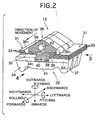
- radially inner side and radially outer side are defined as being with respect to the rotating axis of the drive pulley 6 or the driven pulley 11, and the term “longitudinal direction” is defined as being the direction of movement of the metal elements 32 (see Fig.2 ).
- the metal element 32 formed from a metal plate by punching includes a substantially trapezoidal element body portion 34, and a substantially triangular element head portion 36 connected to the element body portion 34 through a pair of left and right ring slots 35, 35 into which the metal ring assemblies 31, 31 are fitted.
- a pair of pulley contact surfaces 37, 37 are formed on left and right opposite side edges of the element body portion 34 and are capable of being brought into contact with V-faces of the drive pulley 6 and the driven pulley 11.
- Inner contact surfaces 38, 38 and outer contact surfaces 39, 39 are formed respectively on front and rear surfaces of the metal element 32 on radially inner and outer sides with the ring slots 35, 35 interposed therebetween.
- the inner contact surface 38 and the outer contact surface 39 on the front surface of the metal element 32 are shown by drawing oblique lines in Figs.2 and 4 .
- the shapes of the inner contact surface 38 and the outer contact surface 39 on the rear surface of the metal element 32 are the same as those on the front surface of the metal element 32.
- the inner contact surface 38 and the outer contact surface 39 on the rear surface of the preceding metal element 32 can be brought into contact with the inner contact surface 38 and the outer contact surface 39 on the front surface of the succeeding metal element 32, respectively.
- a slope 41 is formed at a lower portion of the front surface of the element body portion 34 with a laterally extending rocking edge 40 interposed therebetween.
- a truncated projection 42 and a truncated recess 43 are formed on front and rear surfaces of the element head portion 36, respectively.
- the metal elements 32 are positioned relative to each other by fitting of the projection 42 provided on the front surface of the succeeding metal element 32 into the recess 43 provided on the rear surface of the preceding metal element 32. A small play is provided between the projection 42 and the recess 43 which are fitted with each other.
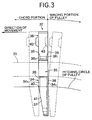
- tapered portions 34 1 are formed at left and right opposite ends of the front and rear surfaces of the element body portion 34 and hence, the lateral width W 1 of each of the inner contact surfaces 38, 38 of the metal element 32 is defined by the tapered portions 34 1 .
- the radially inner end of each of the inner contact surfaces 38, 38 terminates in the rocking edge 40, and the radially outer end of the inner contact surface 38 terminates at a location short of the ring slots 35, 35.
- the rear surface of the element body portion 34 is not provided with the rocking edge 40 and the slope 41 and for this reason, the region of such rear surface excluding the tapered portions 34 1 , 34 1 is on the same plane (see Fig.3 ).
- the inner contact surfaces 38, 38 and the outer contact surfaces 39, 39 are defined as surfaces on which adjacent ones of the metal elements 32 contact with each other and hence, the inner contact surface 38 on the rear surface is of the same shape as the inner contact surfaces 38 on the front surface.
- Tapered portions 36 1 are formed at left and right opposite ends of the front and rear surfaces of the element head portions 36 and hence, the lateral width W 2 of each of the outer contact surfaces 39, 39 on the front and rear surfaces of the metal element 32 is defined by the tapered portions 36 1 .
- the radially inner end of each of the outer contact surfaces 39, 39 and the radially outer end of each of the inner contact surfaces 38, 38 are connected with each other between the ring slots 35, 35.
- the lateral width W 1 of each of the inner contact surfaces 38, 38 of the element body portion 34 is set smaller than the lateral width W 2 of each of the outer contact surfaces 39, 39 of the element head portion 36. Since the outer contact surfaces 39, 39 each of which is a main contact surface having the larger lateral width W 2 are formed on the relatively simple flat plate-shaped element head portion 36, the machining of the contact surfaces 39, 39 is easy, as compared with a case where the contact surfaces 39, 39 are formed on the complicated three-dimensionally shaped element body portion 34.
- the adjacent metal elements 32 lying in an advancing-side chord portion extending from the drive pulley 6 toward the driven pulley 11 transmit the driving force in a state in which the inner contact surfaces 38, 38 on the front and rear surfaces of the metal elements 32 are in contact with each other; the outer contact surfaces 39, 39 on the front and rear surfaces of the metal elements 32 are in contact with each other, and the projection 42 on the front surface of the succeeding metal element 32 has been fitted into the recess 43 on the rear surface of the preceding metal element 32.
- the plurality of metal elements 32 existing in a region from the driven pulley 11 to near the drive pulley 6 can transmit the power in a parallel and longitudinally-arranged state without yawing.
- the lateral width W 2 of each of the outer contact surfaces 39, 39 of the adjacent metal elements 32 is set at a sufficiently large value, the yawing of the metal elements 32 is reliably prevented by the close contact of the outer contact surfaces 39, 39 with each other.
- the metal elements 32 already engaged with the driven pulley 11 are in states in which their lateral movements have been held down and hence, the metal elements 32 reaching near the driven pulley 11 are moved laterally while being slid on the inner contact surfaces 38, 38 and the outer contact surfaces 39, 39, so that they are arranged just behind the metal elements 32 whose lateral movements have already been held down.
- This lateral thrust is transmitted in sequence from the metal element 32 held down on the driven pulley 11 to the succeeding metal element 32 through the projection 42 and the recess 43 fitted with each other.
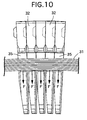
- the metal elements 32 wound around the drive pulley 6 and the driven pulley 11 are pitched relative to each other around the rocking edge 40 and arranged radiately radially of the pulleys 6 and 11.
- the outer contact surfaces 39, 39 remain spaced apart from each other, and the inner contact surfaces 38, 38 are in contact with each other at radially inner edges thereof, i.e., at the rocking edge 40.
- the metal elements 32 can yaw relatively easily, because the lateral width W 1 (namely, the length of the rocking edge 40) of each of the inner contact surfaces 38, 38 is set at a small value.
- the metal elements 32 are meshed with the drive pulley 6 or the driven pulley 11 in a state in which they have been inclined in a yawing direction, the metal elements 32 are corrected into a correct attitude by the yawing of the pulley contact surfaces 37, 37 by a reaction force received from the V-faces in the pulleys 6 and 11.
- the metal elements 32 are corrected into a correct attitude by the yawing of the pulley contact surfaces 37, 37 by a reaction force received from the V-faces in the pulleys 6 and 11.
- the surface pressure acting on the inner contact surfaces 38, 38 having a small area is larger, as compared with the surface pressure acting on the outer contact surfaces 39, 39 having a large area.
- the thickness t 2 of the radially inner portion of the metal element 32 is smaller than the thickness t 1 of the radially outer portion of the metal element 32 due to the compression and deformation caused by the surface pressure, and the section of the metal element 32 is of a tapered shape as exaggeratively shown in Fig.9 . Therefore, when the metal elements 32 are connected in close contact with one another in the chord portion, each of the metal elements 32 is curved radially outwards into an arcuate shape due to the tapered shape as shown in Fig.
- the lateral width W 1 of each of the inner contact surfaces 38, 38 of the element body portion 34 exerts an influence on a hertz stress of the rocking edge 40 generated by the urging force between the metal elements 32 which abut against each other.
- a belt stress at the time of transmitting the maximum horsepower (in the highest speed operational state) should be equal to or less than a critical stress of the material.
- Table shows the minimum value of the lateral width W 1 of each of the inner contact surfaces 38, 38 of the element body portion 34 which is capable of maintaining the maximum hertz stress at 1177N/mm 2 (120 kgf/mm 2 ) or less when the metal belt 15, having the metal elements 32 in which the width of the rocking edge 40 is set at 24 mm, is operated in the maximum horsepower transmitting state (with an input torque of 140 Nm (14.3 kgf-m), an input rotational speed of 6000 rpm, a speed ratio of 0.61, a thrust safety ratio of 1.3, an urging force between the elements of 4187N (427.0 kgf)) while varying the radius R of the rocking edge 40.
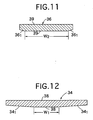
- the tapered portions 34 1 and 36 1 have been formed on the front and rear opposite surfaces of the metal element 32, but in the second embodiment, the tapered portions 34 1 and 36 1 are formed in only one (a front surface) of surfaces of the metal element 32.
- the shapes of the front surfaces of the metal elements 32 are the same as each other and hence, the shapes of the inner contact surfaces 38, 38 and the outer contact surfaces 39, 39 are also substantially the same as each other. According to the second embodiment, the function and effects similar to that in the first embodiment can be obtained, while further simplifying the shape of the metal element 32.
- the hertz stress can be set at a lower value than that in the first embodiment, leading to an advantage in view of the durability.
- the important factors of the shapes of the inner contact surfaces 38, 38 and the outer contact surfaces 39, 39 are the lateral widths W 1 and W 2 , and the other factors may be properly changed.
- the radial height of each of the inner contact surfaces 38, 38 and the outer contact surfaces 39, 39 may be set at any value and, the positional relationship between the projection 42 and the recess 43 may be reversed.
- the inner contact surfaces 38, 38 and the outer contact surfaces 39, 39 have been formed continuously with each other in the embodiments, but may be separated from each other at a location between the left and right ring slots 35, 35.
- the lateral width W 2 of the outer contact surfaces 39, 39 which are in contact with each other when the metal element 32 is in the chord portion is set at a large value to inhibit the yawing of the metal element 32
- the lateral width W 1 of the inner contact surfaces 38, 38 which are in contact with each other when the metal element 32 is at a location where it has been wound around the pulley is set at a small value to permit the yawing of the metal element 32.
- the hertz stress of the rocking edge 40 during the operation it is more advantageous to set the lateral width W 1 of the inner contact surfaces 38, 38 at a large value (see Table 1).
- the ratio W 1 /W 2 in a range of 0.3 ⁇ W 1 /W 2 ⁇ 0.7, which is the ratio between the lateral width W 1 of each of the inner contact surfaces 38, 38 of the element body portion 34 and the lateral width W 2 of each of the outer contact surfaces 39, 39.
- Table 2 and Fig. 13 show the value of the ratio W 1 //W 2 which is capable of maintaining the maximum hertz stress at 1177N/mm 2 (120 kgf/mm 2 ) or less when the metal belt 15 is operated in the maximum horsepower transmitting state (with an input rotational speed of 6000 rpm, a speed ratio of 0.61, a thrust safety ratio of 1.3) while varying the value of the input torque, wherein the metal belt 15 includes the metal elements 32 in which the lateral width W 2 of the outer contact surfaces 39, 39 of the element body portion 34 is set at 20 mm and the radius R of the rocking edge 40 is set at 10 mm.
- the urging force between the elements is increased as the input torque is increased, and with this, the necessary lateral width W 1 of the inner contact surfaces 38, 38 of the element body portion 34 is increased and hence, the ratio W 1 /W 2 is also increased. Therefore, in order to ensure the durability of the metal element in a range of 78Nm (8 kgf-m) to 176Nm (18 kgf-m) which is a practical input torque, it is desirable to set the value of the ratio W 1 /W 2 in a range of 0.3 ⁇ W 1 /W 2 ⁇ 0.7 making allowance for the safety ratio.
Landscapes
- Engineering & Computer Science (AREA)
- General Engineering & Computer Science (AREA)
- Mechanical Engineering (AREA)
- Transmissions By Endless Flexible Members (AREA)
Claims (2)
- Riemen für ein kontinuierlich verstellbares Getriebe, umfassend eine große Anzahl von Metallelementen (32), welche auf Metallring-Anordnungen (31) gelagert sind, von denen jede eine Mehrzahl von endlosen Metallringen (33) umfasst, die aufeinander laminiert sind, wobei der Riemen um eine Antrieb-Riemenscheibe (6) und eine Abtrieb-Riemenscheibe (11) gewunden ist, um eine Antriebskraft zwischen den beiden Riemenscheiben (6 und 11) zu übertragen,
wobei jedes von den Metallelementen (32) Ringschlitze (35), in welche die Metallring-Anordnungen (31) eingepasst sind, einen Element-Körper-Abschnitt (34), welcher auf einer radial inneren Seite von den Ringschlitzen (35) angeordnet ist, und einen Element-Kopf-Abschnitt (36) umfasst, welcher auf einer radial äußeren Seite von den Ringschlitzen (35) angeordnet ist
dadurch gekennzeichnet, dass der Element-Körper-Abschnitt (34) und der Element-Kopf-Abschnitt (36) jeweils mit einer Kontaktfläche (38 und 39) ausgebildet sind, an welcher die Metallelemente (32) miteinander in Kontakt stehen können, wobei eine seitliche Breite (W1) von der Kontaktfläche (38) von dem Element-Körper-Abschnitf (34) kleiner ist als eine seitliche Breite (W2) von der Kontaktfläche (39) von dem Element-Kopf-Abschnitt (36). - Riemen für ein kontinuierlich verstellbares Getriebe nach Anspruch 1, wobei die Metallelemente (32) relativ zueinander positioniert sind, indem ein Vorsprung (42) und eine Vertiefung (43), die an einer und der anderen von Vorder- und Rückseite davon ausgebildet sind, ineinander eingepasst sind.
Applications Claiming Priority (5)
| Application Number | Priority Date | Filing Date | Title |
|---|---|---|---|
| JP9866598 | 1998-04-10 | ||
| JP9866598 | 1998-04-10 | ||
| JP3480299 | 1999-02-12 | ||
| JP03480299A JP3715126B2 (ja) | 1998-04-10 | 1999-02-12 | 無段変速機用ベルト |
| PCT/JP1999/001109 WO1999053218A1 (en) | 1998-04-10 | 1999-03-08 | Belt for continuously variable transmission |
Publications (3)
| Publication Number | Publication Date |
|---|---|
| EP1069342A1 EP1069342A1 (de) | 2001-01-17 |
| EP1069342A4 EP1069342A4 (de) | 2006-05-31 |
| EP1069342B1 true EP1069342B1 (de) | 2011-11-09 |
Family
ID=26373647
Family Applications (1)
| Application Number | Title | Priority Date | Filing Date |
|---|---|---|---|
| EP99945691A Expired - Lifetime EP1069342B1 (de) | 1998-04-10 | 1999-03-08 | Riemen für stufenlos regelbares Getriebe |
Country Status (4)
| Country | Link |
|---|---|
| US (1) | US6440025B1 (de) |
| EP (1) | EP1069342B1 (de) |
| JP (1) | JP3715126B2 (de) |
| WO (1) | WO1999053218A1 (de) |
Families Citing this family (26)
| Publication number | Priority date | Publication date | Assignee | Title |
|---|---|---|---|---|
| DE60005746T2 (de) * | 1999-06-18 | 2004-04-29 | Honda Giken Kogyo K.K. | Riemen für stufenlos regelbares Getriebe |
| JP3669680B2 (ja) * | 2000-01-17 | 2005-07-13 | 本田技研工業株式会社 | 無段変速機用ベルト |
| DE60112176T2 (de) | 2000-05-26 | 2005-12-29 | Honda Giken Kogyo K.K. | Verfahren und Vorrichtung zum Stanzen von Teilen von einem Riemen für stufenlos regelbares Getriebe |
| JP4502578B2 (ja) * | 2000-12-28 | 2010-07-14 | ボッシュ トランズミッション テクノロジー ベー.ファウ. | ベルト |
| WO2002053935A1 (en) * | 2000-12-28 | 2002-07-11 | Van Doorne's Transmissie B.V. | Belt |
| WO2002053937A1 (en) * | 2000-12-28 | 2002-07-11 | Van Doorne's Transmissie B.V. | Belt |
| WO2002053938A1 (en) * | 2000-12-28 | 2002-07-11 | Van Doorne's Transmissie B.V. | Belt |
| JP2003056649A (ja) * | 2001-08-10 | 2003-02-26 | Honda Motor Co Ltd | 無段変速機用ベルト |
| NL1021661C2 (nl) * | 2002-10-16 | 2004-04-27 | Doornes Transmissie Bv | Drijfriem met dwarselementen en stansinrichting voor de vervaardiging van dwarselementen. |
| JP4129448B2 (ja) | 2004-10-08 | 2008-08-06 | 本田技研工業株式会社 | 無段変速機用ベルト |
| CN101198807B (zh) * | 2005-06-13 | 2010-12-01 | 罗伯特·博世有限公司 | 用于无级变速器的传动带以及制造用于这种传动带的横向元件的方法 |
| JP2008116010A (ja) * | 2006-11-07 | 2008-05-22 | Toyota Central R&D Labs Inc | 動力伝達用無端ベルト |
| US8272984B2 (en) * | 2007-11-20 | 2012-09-25 | Aisin Aw Co., Ltd. | Endless metal belt |
| CN101910677B (zh) * | 2007-12-24 | 2013-05-01 | 罗伯特·博世有限公司 | 传动皮带 |
| NL1038481C2 (en) * | 2010-12-28 | 2012-07-02 | Bosch Gmbh Robert | Transverse element with a protruding conical stud for a drive belt. |
| EP2924316A4 (de) * | 2012-11-26 | 2016-01-20 | Toyota Motor Co Ltd | Riemen für ein stufenloses getriebe und herstellungsverfahren dafür |
| JP6221045B2 (ja) * | 2012-12-27 | 2017-11-01 | ダイハツ工業株式会社 | 無段変速機用金属ベルト |
| JP6506062B2 (ja) * | 2015-03-24 | 2019-04-24 | 本田技研工業株式会社 | 無段変速機用金属エレメントの製造方法 |
| US11047451B2 (en) * | 2016-05-18 | 2021-06-29 | Aisin Aw Co., Ltd. | Transmission belt |
| JP6444355B2 (ja) * | 2016-11-04 | 2018-12-26 | 本田技研工業株式会社 | 無段変速機用金属エレメントおよび無段変速機用金属エレメントの製造方法 |
| US11149820B2 (en) * | 2017-03-03 | 2021-10-19 | Aisin Aw Co., Ltd. | Element designing method and power transfer belt |
| JP6523381B2 (ja) * | 2017-07-28 | 2019-05-29 | 本田技研工業株式会社 | 無段変速機用金属エレメントの製造方法 |
| CN107816509B (zh) * | 2017-11-02 | 2021-01-19 | 陈学琴 | 活片无极变速器传动带 |
| JP6621495B2 (ja) * | 2018-04-03 | 2019-12-18 | 本田技研工業株式会社 | 無段変速機用金属エレメントおよび無段変速機用金属エレメントの製造方法 |
| JP7028204B2 (ja) * | 2019-02-12 | 2022-03-02 | トヨタ自動車株式会社 | 無段変速機 |
| NL1043501B1 (en) * | 2019-12-10 | 2021-08-31 | Bosch Gmbh Robert | A transverse segment for a drive belt and a drive belt for a continuously variable transmission including the transverse segment and a ring stack |
Family Cites Families (9)
| Publication number | Priority date | Publication date | Assignee | Title |
|---|---|---|---|---|
| DE3466042D1 (de) * | 1983-07-29 | 1987-10-15 | Bando Chemical Ind | V belt |
| JPS6196036U (de) * | 1984-11-29 | 1986-06-20 | ||
| JPH0537067Y2 (de) * | 1986-05-28 | 1993-09-20 | ||
| JPS6333046A (ja) | 1986-07-28 | 1988-02-12 | Nec Corp | Icカ−ド式電話機 |
| JPS63115937A (ja) * | 1986-10-30 | 1988-05-20 | Fuji Heavy Ind Ltd | 無段変速機用vベルト |
| NL8700156A (nl) * | 1987-01-23 | 1988-08-16 | Doornes Transmissie Bv | Drijfriem, dwarselement voor een drijfriem en werkwijze en inrichting voor de vervaardiging daarvan. |
| NL9001263A (nl) * | 1990-06-05 | 1992-01-02 | Doornes Transmissie Bv | Geprofileerd dwarselement. |
| JP3197023B2 (ja) * | 1991-05-29 | 2001-08-13 | ファン ドールネズ トランスミッシー ベスローテン フェンノートチャップ | 輪郭をつけたベルト素子 |
| JP3323448B2 (ja) * | 1998-10-30 | 2002-09-09 | 福寿工業株式会社 | 金属ベルト用エレメント及び金属ベルト |
-
1999
- 1999-02-12 JP JP03480299A patent/JP3715126B2/ja not_active Expired - Lifetime
- 1999-03-08 EP EP99945691A patent/EP1069342B1/de not_active Expired - Lifetime
- 1999-03-08 WO PCT/JP1999/001109 patent/WO1999053218A1/ja not_active Ceased
- 1999-09-08 US US09/646,891 patent/US6440025B1/en not_active Expired - Lifetime
Also Published As
| Publication number | Publication date |
|---|---|
| WO1999053218A1 (en) | 1999-10-21 |
| EP1069342A1 (de) | 2001-01-17 |
| JPH11351336A (ja) | 1999-12-24 |
| US6440025B1 (en) | 2002-08-27 |
| JP3715126B2 (ja) | 2005-11-09 |
| EP1069342A4 (de) | 2006-05-31 |
Similar Documents
| Publication | Publication Date | Title |
|---|---|---|
| EP1069342B1 (de) | Riemen für stufenlos regelbares Getriebe | |
| US6626782B1 (en) | Belt for continuously variable transmission | |
| EP1061285B1 (de) | Riemen für stufenlos regelbares Getriebe | |
| JP3715166B2 (ja) | 無段変速機用ベルト | |
| EP1069341B1 (de) | Riemen für stufenlos regelbares Getriebe | |
| US6612954B2 (en) | Belt for continuously variable transmission | |
| EP1069343B1 (de) | Riemen für stufenloses getriebe | |
| US6270437B1 (en) | Belt for continuously variable transmission | |
| WO2004048804A1 (ja) | 無段変速機用金属ベルト | |
| EP1179691B1 (de) | Riemen für ein stufenlos regelbares Getriebe | |
| US7077775B2 (en) | Oxa(thia)zolidine compounds, process for preparation thereof and anti-inflammatory agents | |
| JP2002235808A (ja) | 無段変速機用ベルト | |
| US6336884B1 (en) | Belt for continuously variable transmission | |
| JP3696475B2 (ja) | 無段変速機用ベルトにおける金属エレメントの組み合わせ方法 | |
| JP2003120758A (ja) | 無段変速機用ベルト |
Legal Events
| Date | Code | Title | Description |
|---|---|---|---|
| PUAI | Public reference made under article 153(3) epc to a published international application that has entered the european phase |
Free format text: ORIGINAL CODE: 0009012 |
|
| 17P | Request for examination filed |
Effective date: 20000928 |
|
| AK | Designated contracting states |
Kind code of ref document: A1 Designated state(s): DE FR GB NL |
|
| A4 | Supplementary search report drawn up and despatched |
Effective date: 20060419 |
|
| 17Q | First examination report despatched |
Effective date: 20061127 |
|
| GRAP | Despatch of communication of intention to grant a patent |
Free format text: ORIGINAL CODE: EPIDOSNIGR1 |
|
| RTI1 | Title (correction) |
Free format text: BELT FOR CONTINUOUSLY VARIABLE TRANSMISSION |
|
| GRAS | Grant fee paid |
Free format text: ORIGINAL CODE: EPIDOSNIGR3 |
|
| GRAA | (expected) grant |
Free format text: ORIGINAL CODE: 0009210 |
|
| AK | Designated contracting states |
Kind code of ref document: B1 Designated state(s): DE FR GB NL |
|
| REG | Reference to a national code |
Ref country code: GB Ref legal event code: FG4D |
|
| RIN2 | Information on inventor provided after grant (corrected) |
Inventor name: OHNUKI, MOTONORI |
|
| REG | Reference to a national code |
Ref country code: DE Ref legal event code: R096 Ref document number: 69943853 Country of ref document: DE Effective date: 20111229 |
|
| REG | Reference to a national code |
Ref country code: NL Ref legal event code: VDEP Effective date: 20111109 |
|
| PG25 | Lapsed in a contracting state [announced via postgrant information from national office to epo] |
Ref country code: NL Free format text: LAPSE BECAUSE OF FAILURE TO SUBMIT A TRANSLATION OF THE DESCRIPTION OR TO PAY THE FEE WITHIN THE PRESCRIBED TIME-LIMIT Effective date: 20111109 |
|
| PLBE | No opposition filed within time limit |
Free format text: ORIGINAL CODE: 0009261 |
|
| STAA | Information on the status of an ep patent application or granted ep patent |
Free format text: STATUS: NO OPPOSITION FILED WITHIN TIME LIMIT |
|
| 26N | No opposition filed |
Effective date: 20120810 |
|
| GBPC | Gb: european patent ceased through non-payment of renewal fee |
Effective date: 20120308 |
|
| REG | Reference to a national code |
Ref country code: DE Ref legal event code: R097 Ref document number: 69943853 Country of ref document: DE Effective date: 20120810 |
|
| REG | Reference to a national code |
Ref country code: FR Ref legal event code: ST Effective date: 20121130 |
|
| REG | Reference to a national code |
Ref country code: DE Ref legal event code: R084 Ref document number: 69943853 Country of ref document: DE Effective date: 20121113 |
|
| PG25 | Lapsed in a contracting state [announced via postgrant information from national office to epo] |
Ref country code: GB Free format text: LAPSE BECAUSE OF NON-PAYMENT OF DUE FEES Effective date: 20120308 Ref country code: FR Free format text: LAPSE BECAUSE OF NON-PAYMENT OF DUE FEES Effective date: 20120402 |
|
| PGFP | Annual fee paid to national office [announced via postgrant information from national office to epo] |
Ref country code: DE Payment date: 20130306 Year of fee payment: 15 |
|
| REG | Reference to a national code |
Ref country code: DE Ref legal event code: R119 Ref document number: 69943853 Country of ref document: DE |
|
| REG | Reference to a national code |
Ref country code: DE Ref legal event code: R119 Ref document number: 69943853 Country of ref document: DE Effective date: 20141001 |
|
| PG25 | Lapsed in a contracting state [announced via postgrant information from national office to epo] |
Ref country code: DE Free format text: LAPSE BECAUSE OF NON-PAYMENT OF DUE FEES Effective date: 20141001 |