EP0135710B1 - Keilriemen - Google Patents
Keilriemen Download PDFInfo
- Publication number
- EP0135710B1 EP0135710B1 EP84108858A EP84108858A EP0135710B1 EP 0135710 B1 EP0135710 B1 EP 0135710B1 EP 84108858 A EP84108858 A EP 84108858A EP 84108858 A EP84108858 A EP 84108858A EP 0135710 B1 EP0135710 B1 EP 0135710B1
- Authority
- EP
- European Patent Office
- Prior art keywords
- belt
- block
- convexed
- concaved
- pulley
- Prior art date
- Legal status (The legal status is an assumption and is not a legal conclusion. Google has not performed a legal analysis and makes no representation as to the accuracy of the status listed.)
- Expired
Links
Images


Classifications
-
- F—MECHANICAL ENGINEERING; LIGHTING; HEATING; WEAPONS; BLASTING
- F16—ENGINEERING ELEMENTS AND UNITS; GENERAL MEASURES FOR PRODUCING AND MAINTAINING EFFECTIVE FUNCTIONING OF MACHINES OR INSTALLATIONS; THERMAL INSULATION IN GENERAL
- F16G—BELTS, CABLES, OR ROPES, PREDOMINANTLY USED FOR DRIVING PURPOSES; CHAINS; FITTINGS PREDOMINANTLY USED THEREFOR
- F16G5/00—V-belts, i.e. belts of tapered cross-section
- F16G5/16—V-belts, i.e. belts of tapered cross-section consisting of several parts
- F16G5/166—V-belts, i.e. belts of tapered cross-section consisting of several parts with non-metallic rings
Definitions
- This invention relates to a V belt in general of the kind as referred by the features according to the opening portion of claim 1.
- a prior art V belt of this kind comprises according to the FR-A-2 437 531 a plurality of blocks which are adherent with two endless load carriers whereby the particular adhesion of the blocks is obtained by a vulcanisation of the elastomeric material in which the tensile members of the load carriers are as well adhesively embedded.
- the V belt 1 is composed of two load carriers 2, 3 and a plurality of blocks 4 mounted compactly on the load carriers 2, 3 in the lengthwise direction of the belt.
- the blocks 4 are made of non-metallic material, such as plastics or hard rubber, having the large coefficient of friction and high abrasion resistance.
- the sides 4a and 4b of the block 4 are slant, forming a belt angle a to correspond substantially to the groove angle of a pulley.
- Opposed surfaces 4e, 4f at the underside of adjoining blocks 4 are such that the surface 4f is slant but the surface 4e is perpendicular, thereby forming the angle ⁇ to correspond to the minimum pitch diameter of the V belt.
- slots 5, which are open at the side surfaces 4a, 4b respectively and extend toward the central part of the block 4 are formed at the sides of the block 4.
- projections 6 are provided at upper surfaces 5a, 6a and lower surfaces 5b, 6b of each slot.
- the upper surface 4c and the lower surface 4d of the block 4 are formed in the convexed shape and the concaved shape respectively.
- Each of the load carriers 2, 3 comprises a plurality of tensile members 7 arranged substantially on the same plane, elastomers 8, 9 to support the tensile members 7 and woven fabrics 10, 10 and 11, 11 embedded close to the upper surfaces and the lower surfaces of the load carriers 2, 3 respectively.
- One side 2a, 3a of each of the load carriers 2, 3 has an incline which is . substantially the same as that of the side surfaces 4a, 4b of the block 4, but the other side 2b, 3b has no such inclination. As shown in FIG.
- concaved parts (only 3c, 3d of the load carrier 3 are shown in the drawing) which engage with the convexed parts made in the slots 5, 6 of the block 4 are made at the upper surface and the lower surface of each of the load carriers 2, 3.
- the convexed part of the block 4 and the concaved part of the load carriers 2, 3 are a means of power transmission between the block 4 and the load carriers 2, 3 and it is possible to provide the concaved part at the block side and the convexed part at the load carrier side for engagement with each other.
- the slots 5, 6 of the block 4 engage with either the upper surface or the lower surface of the load carriers 2, 3.
- Tensile members 7, 7 which compose the load carriers 2, 3 are generally made of synthetic fibers, such as polyamide, polyester, polyaramid, etc., inorganic fibers such as steel fiber, glass fiber, carbon fiber, etc., twisted cords of mixed spinning or mixed twisting of the foregoing fibers, woven fabric or sheet-like substance.
- synthetic fibers such as polyamide, polyester, polyaramid, etc.
- inorganic fibers such as steel fiber, glass fiber, carbon fiber, etc., twisted cords of mixed spinning or mixed twisting of the foregoing fibers, woven fabric or sheet-like substance.
- materials having a high compression Young's modulus, high abrasion resistance, etc. are required for elastomers 8, 9 and conventional synthetic rubber is used generally for them.
- Materials having high flexibility and high abrasion resistance are required for woven fabrics 10, 11 and fabrics woven of mixed spun yarn or mixed twisted yarn of cotton, polyamide, polyester, polyaramid, etc. are used generally for them.
- woven fabric can be
- the side surfaces 2a, 3a of the load carriers 2, 3 are on the same plane with the side surfaces 4a, 4b of the block 4 when they engage with the groove of a transmission pulley (refer to FIG. 5).
- the two load carriers 2, 3 and the block 4 are immovable in lengthwise direction of the V belt 1 but the block 4 is detachable in transverse direction of the V belt 1.
- FIG. 5 showing the state of power transmission when the V belt 1 engages with the pulley 21 and is subjected to a lateral pressure force
- the side surfaces 4a, 4b of the block 4 and the side surfaces 2a, 3a are substantially on the same plane respectively.
- friction transmission force with the pulley 21 is generated at all side surfaces 4a, 4b, 2a, 3a.
- the block 4 made of plastics, hard rubber or the like has a large compression Young's modulus and therefore the V belt 1 stands a high lateral pressure and the transmission torque becomes large.
- the side surfaces 2a, 3a of the load carriers 2, 3 need not be on the same plane with the side surfaces 4a, 4b of the block 4.
- the specific gravity of the block 4 is usually less than 2.0 and therefore the V belt 1 is considerably light in weight, as compared with a metallic V belt, and its centrifugal force is small. This means that the V belt 1 is suitable for high speed running and is advantageous in the aspect of safety.
- the load carriers 2, 3 generally present the appearance of a thin, flat belt, have very good flexibility and keep slight heat in running condition. Such features of the load carrier ensure a longer belt life.
- each block 4 is immovable in lengthwise direction of the belt due to engagement of the convexed parts provided at the slots 5, 6 of the block 4 with the concaved parts provided at the upper surface and the lower surface of the load carriers 2, 3 but is made detachable in its transverse direction, fitting-in can be done easily.
- V belt 1 is gradually modified to suit the grooves of the pulley 21 due to wear of side surfaces of the block 4 and the load carriers 2, 3 which are in engagement state, high processing precision is not required for both the block 4 and the load carriers 2, 3.
- FIG. 6 shows a V belt 31 which is improved further in flexibility.
- a block 32 has a convexed part 33 at the upper surface of a slot and the radius of curvature R to suit the minimum pitch diameter of the V belt 31 is made at the lower surface of the slot.
- a load carrier 34 has a concaved part 34a at its upper surface but has no ruggedness at its lower surface.
- FIG. 7 shows a V belt 41 which can prevent earlier breakage of load carriers due to bending fatigue of tensile members in the load carrier.
- a convexed part 43 provided at a lower surface 45 of a slot of a block 42 is made flat at its top surface 43a and this flatness of the top surface 43a leaves a vacant space in engagement with a concaved part 3d of the load carriers 3. Accordingly, as shown in FIG.
- the load carrier 3 contacts a lower surface 45 which is adapted to have a radius of curvature R under the condition where the V belt 41 is wound round pulleys and the load carrier 3 does not bend at the line A,-A,, the line Ag-A 2 and the line A3 - A3, with the result that tensile members 7 of the load carrier 3 (and the load carrier 2) are free from bending fatigue.
- FIG. 10 shows a V belt which has good flexibility and is applicable to a pulley of small diameter.
- this V belt 61 it is so adapted that a radius of curvature R, of a convexed part 63a provided at the lower surface of a slot (only the slot 63 is shown) and a radius of curvature R 2 of a concaved part 66 provided at a lower surface 65 of a load carrier 64 are expressed by the formula R, ⁇ R 2 .
- V belt 61 engaged with a pulley at the minimum pitch diameter
- the concaved part 66 provided at the lower surface 65 of the load carrier 64 is compressed and deformed at the part below the tensile member 7 of the load carrier 64 but, in reality, is deformed only to such an extent that it conforms substantially with the convexed part 63a provided at the slot 63 of the block 62.
- teh V belt 61 fits a pulley at all times and is free from loss of flexibility.
- the concaved part at the lower surface of the load carrier is composed by only the curved surface of the radius of curvature R 2 as mentioned above, but it is possible to compose it by the combination of a curved surface and a plane surface, namely, it is possible to form a vacant space between surfaces of the convexed part and the concaved part whose front and rear sides in lengthwise direction of belt are made plane.
- FIG. 11 shows a V belt 71 having a block 72, 72 whose side surfaces 72a, 72b project slightly outwardly with a pitch line L as the center for preventing breakage of the block.
- the side surfaces 72a, 72b of the block 72 are in slightly convex surface shape as if they were projected outwardly and therefore lateral pressure force Na (Na i + Na 2 ) and Nb (Nb 1 + Nb 2 ) are well balanced and no unreasonable load (bending stress) is applied to the block 72.
- the above-mentioned "convexd surface shape” includes the curved surface shape and the combination of two plan surfaces in angle shape.
- FIG. 13 shows a V belt having good affinity to a pulley.
- This V belt 81 has many minute projections 83 at the both side surfaces (only the side surface 82a is shown). These projections 83 are so formed that they become thinner toward a forward end, like a conical form, a truncated cone, etc., namely, it is so adapted that the sectional area of the projection 83 in parallel with the groove surface of the pulley becomes smaller as it is closer to the groove surface of the pulley.
- the V belt 81 in the state where the block 82 and the load carrier 3,2 engage with the pulley 21, wears at the side surfaces of the block 82 and is modified to suit the groove of the pulley 21. Since the side surfaces of the block 82 have minute projections 83, the V belt 81 takes the shape to suit the groove of the pulley easily. Therefore, no severe dimensional precision is required for the block 82 and the load carrier 3 (and 2).
- minute projections are made uniformly on all the side surfaces of the block 82 but this arrangement is not necessarily required and the distribution density of projections can be varied at each part of the side surfaces.
- FIG. 14 shows a V belt which can prevent generation of noise, such as clash of blocks due to shaking of blocks.
- this V belt 91 upper opposed surfaces 92a, 92b of blocks 92 above the pitch line L are formed in such a fashion that the sufface 92a is perpendicular but the surface 92b is slant, forming the minimum angle 6 which leaves between the opposed surfaces a vacant space 93 by which adjoining blocks to not contact each other even if longitudinal oscillation (longitudinal oscillation of blocks 92) of the V belt 91 took place during running and accordingly generation of noise can be prevented.
- a block 101 shown in FIG. 15 (a) has an upper opposed perpendicular surface 101 and an upper opposed curved surface 101 b.
- a block 102 shown in FIG. 15 (b) has upper opposed surfaces 102a, 102b, both of which are slant and a block 103 shown in FIG. 15 (c) has upper opposed surfaces 103a, 103b, both of which are curved surfaces.
- any block will do so long as a vacant space between the upper opposed surfaces expands outwardly in vertical direction.
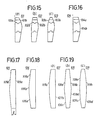
- a block 104 shown in FIG. 16 has a perpendicularly flat surface 104b near the pitch line L at the side where an upper opposed slant surface 104a is made to form a vacant space between the upper opposed surfaces.
- a block 105 shown in FIG. 16 In order to prevent noise caused by lateral shake by forming a vacant space which expands outwardly in right and left directions from the central part of block between the opposed blocks, a block 105 shown in FIG.
- a block 17 has right and left front side opposed surfaces 105a, 105b which slant in such a fashion that said surfaces become thinner toward the right and left sides, but such slant may be made either of 105a and 1 05b.
- the angle ⁇ is an angle at which blocks 105, 105 do not collide with each other even if lateral shake took place.
- a block 106 shown in FIG. 18 has slant right and left front side opposed surfaces 106a, 106b which are combined by a flat surface 106b.
- a block 107 shown in FIG. 19 (a) has right and left front side opposed surfaces 107a, 107b which are formed in curved surface shape, but such curved surface shape may be made either of 107a and 107b.
- a block 109 shown in FiG. 1919 (c) has right and left opposed surfaces at front and rear sides 109a, 109b, 109c, 109d, all of which are curved surfaces.
- FIG. 20 shows a V belt 111 which involves slight noise and has a longer usable life.
- a block 112 of this V belt 111 as shown in FIG. 21, has a coating layer 112B of soft substance B provided integrally for opposed surfaces 112a, 112b of a block proper 112A made of hard resin A which makes contact with the pulley surface of a pulley for frictional transmission. This coating layer 112B will not exfoliate in use.
- the resin A is free from buckling and deformation by pressure from the pulley side and is not melted by heat generated by slip on the pulley surface.
- hard resin having high heat resistance is used, for exaple, thermosetting resin such as phenol resin, polyimido resin, epoxy resin, etc., or thermoplastic resin having high heat resistance such as polyphenylene sulfide resin (PPS), aromatic polyamide resin, polyetherimido resin, polyamidoimido resin, polyether ethereal ketone resin, etc. are used singly or in compounding with short fiber, etc.
- Resin A is a hard resin of very high elasticity and if the block 112 is composed by this resin without coating layers 112B, impact sound between block propers 112A is very high.
- thermoplastic resin such as engineering plastics, polyacetal, polyptylenterephthalate, aliphatic polyamide resin, polyethylene, polypropylene, ethylenpropylene copolymer, ethylene - vinyl acetate copolymer, plasticized PVC, thermoplastic urethane, etc. or thermoplastic elastomer or bridge type elastomer, such as natural rubber, synthetic rubber, polyurethane, etc., all of which are less than 30,OOOKg/cm 2 in the coefficient of elasticity.
- Integration of the resin A and the soft substance B can be effected easily by the so-called multicolor injection process, if both of them are thermoplastic resin.
- a boundary surface between the resin A and the soft substance B can be made rugged to increase adhesive strength.
- Integration of the resin A and the soft substance B can also be effected by applying a solution or liquid of the soft substance B to the surface of the resin A and then drying it or hardening it by heating (vulcanizing it), where necessary.
- an adhesion treatment process can be employed for the interface. If the side surface of the resin A (the friction surface with the pulley) is covered with the soft substance B, it must be removed by grinding.
- the coating layer 112B is usually made as thin as possible.
- the thickness of the coating layer is usually selected from within the range of 0.2-1.5 mm.
- the coating layer 112B comprising the soft substance B is formed at the opposed surfaces 112a, 112b, but the coating layer may be formed only at one surface 112a (or 112b) as shown in FIG. 22.
- FIG. 25 (a), (b) show a block 131 of the V belt which inhibits wear of the load carrier and prevents breakage of it.
- This block 131 comprises a block proper 131A covered with a lubricative resin layer 131 B and therefore the contact surface between the load carrier and the pulley wears less due to the lubricating action of the lubricative resin layer 131B, with the result that the load carrier is neither cracked nor broken.
- the above lubricative resin layer 131 B is provided at the portions where the block 131 contacts the load carrier, namely, the inside surface of a slot 132, 133 (the upper and lower surfaces 132a, 133a, 132b, 133b and the side surface 132c, 133c). This is enough for preventing the wear of the load carrier but it is of course effective to cover the whole surface of the block 131, excepting the contact surfaces with the pulley (side surfaces 131a, 131b) with the lubricative resin layer 131D, as shown in FIG. 26.
- the material of the block proper 131A of the block 131 hard resin having the high coefficient of friction is used to let the block 131 stand the lateral pressure from the pulley and do the friction transmitting.
- the material of the lubricative resin layer 131B, 131D self-lubricative resin such as polyacetal resin, nylon resin, teflon resin, etc. can be used as they are or resin having no self-lubricacy can be used with addition of a solid lubricant, such as graphite, carbon fiber, molybdenum desulfide, etc., or a liquefied lubricant.
- a block 141 may be constructed as shown in FIG. 27.
- reference number 141A is a block proper and reference number 141 B is a lubricative layer.
- the basic shape of this block 141 is similar to the block 32 of the V belt shown in FIG. 6.
- FIG. 28 shows a V belt 151 having good heat- radiativity and good fitness to the pulley, yet lighter in weight.
- a plurality of heat radiating ribs 152a, 152b are made at the upper and lower end portions of the block 152 in the transverse direction of belt, as shown in FIG. 29, to increase the surface area and to compose the heat-radiating portions A i , A 2 .
- a hollow portion 152c which passes through the block in lengthwise direction of belt is formed at the lower part of the block 152 as a heat-radiating portion A3.
- heat-radiating portions A,, A 2 , A3 contribute to the lightening in weight of the block 152, especially the hollow portion 152c which constitutes the heat-radiating portion A3 regulate the rigidity of the block 152 in transverse direction of belt and improves fitness to the pulley on which the V belt 151 is wound. Therefore, the V belt 151 stands the high lateral pressure thanks to the block 152 having a large compression Young's modulus and is imparted with high transmitting ability.
- the V belt 151 when the V belt 151 is in the state of power transmitting, the amount of heat generated at the V belt 151 (especially at the block 152) is emitted effectively into the atmosphere owing to the multiplied effect of the heat-radiating portions A 1' A 2 , A3 and thus overheating of the V belt 151 (the block 152) can be prevented.
- the block 152 (the V belt 151) can be wound round the pulley fittingly.
- a comparatively large hollow portion 152c is provided at the lower part of the block 152 but the arrangement of a plurality of hollow portions 152d, as shown in FIG. 30, produces a similar effect.
- Positions at which hollow portions are made are not necessarily limited and it is possible to provide heat-radiating ribs 153a, 153b in lengthwise direction of belt and the hollow portion 153c at the upper and lower surfaces of the block 153, as shown in FIG. 31.
- the embodiments described hereinabove refer to the V belt which obtains the friction transmitting force with the pulley at the side surfaces of the V block and at the side surfaces of the load carrier as a whole but is applicable to the V belt which obtains the friction transmitting force at only the side surfaces (a part or the whole) of the block.
Claims (19)
Applications Claiming Priority (18)
| Application Number | Priority Date | Filing Date | Title |
|---|---|---|---|
| JP58139895A JPS6049151A (ja) | 1983-07-29 | 1983-07-29 | Vベルト |
| JP139895/83 | 1983-07-29 | ||
| JP139741/83U | 1983-09-08 | ||
| JP13974183U JPS6047940U (ja) | 1983-09-08 | 1983-09-08 | Vベルト |
| JP26532/84U | 1984-02-24 | ||
| JP2653284U JPS60138054U (ja) | 1984-02-24 | 1984-02-24 | Vベルト |
| JP26531/84U | 1984-02-24 | ||
| JP2653184U JPS60138053U (ja) | 1984-02-24 | 1984-02-24 | Vベルト |
| JP32567/84U | 1984-03-06 | ||
| JP3256784U JPS60143953U (ja) | 1984-03-06 | 1984-03-06 | Vベルト |
| JP3344184U JPS60145646U (ja) | 1984-03-07 | 1984-03-07 | Vベルト |
| JP33441/84U | 1984-03-07 | ||
| JP3578684U JPS60147839U (ja) | 1984-03-12 | 1984-03-12 | Vベルト |
| JP35786/84U | 1984-03-12 | ||
| JP62550/84U | 1984-04-26 | ||
| JP6255084U JPS60173746U (ja) | 1984-04-26 | 1984-04-26 | Vベルト |
| JP6254884U JPS60173744U (ja) | 1984-04-26 | 1984-04-26 | Vベルト |
| JP62548/84U | 1984-04-26 |
Publications (2)
| Publication Number | Publication Date |
|---|---|
| EP0135710A1 EP0135710A1 (de) | 1985-04-03 |
| EP0135710B1 true EP0135710B1 (de) | 1987-09-09 |
Family
ID=27576795
Family Applications (1)
| Application Number | Title | Priority Date | Filing Date |
|---|---|---|---|
| EP84108858A Expired EP0135710B1 (de) | 1983-07-29 | 1984-07-26 | Keilriemen |
Country Status (4)
| Country | Link |
|---|---|
| US (1) | US4655732A (de) |
| EP (1) | EP0135710B1 (de) |
| CA (1) | CA1211301A (de) |
| DE (1) | DE3466042D1 (de) |
Cited By (12)
| Publication number | Priority date | Publication date | Assignee | Title |
|---|---|---|---|---|
| EP0213627A1 (de) * | 1985-09-04 | 1987-03-11 | Bando Chemical Industries, Ltd. | Keilriemen |
| EP0240936A2 (de) * | 1986-04-05 | 1987-10-14 | Bando Chemical Industries, Ltd. | Keilriemen |
| EP0240912A2 (de) * | 1986-03-31 | 1987-10-14 | Mitsuboshi Belting Ltd. | Schwerbelastbarer Treibriemen |
| EP0257646A2 (de) * | 1986-08-28 | 1988-03-02 | Bando Chemical Industries, Ltd. | Keilriemen mit Querkörpern |
| EP0306304A1 (de) * | 1987-05-29 | 1989-03-08 | Mitsuboshi Belting Ltd. | Schwerbelastbarer Treibriemen |
| US5776023A (en) * | 1995-07-13 | 1998-07-07 | Bando Chemical Industries, Ltd. | Heavy-duty power transmission v-belt |
| WO2001092756A1 (de) | 2000-06-02 | 2001-12-06 | Contitech Antriebssysteme Gmbh | Keilriemen zur verlustarmen leistungsübertragung |
| WO2001092757A1 (de) | 2000-06-02 | 2001-12-06 | Contitech Antriebssysteme Gmbh | Keilriemen zur verlustarmen leistungsübertragung |
| WO2001094810A1 (de) | 2000-06-02 | 2001-12-13 | Contitech Antriebssysteme Gmbh | Keilriemen zur verlustarmen leistungsübertragung |
| WO2002040890A1 (de) | 2000-11-18 | 2002-05-23 | Contitech Antriebssysteme Gmbh | Hochleistungskeilriemen |
| DE102007024940A1 (de) | 2007-05-29 | 2008-12-04 | Contitech Antriebssysteme Gmbh | Hybridkeilriemen |
| DE102008045017A1 (de) | 2008-08-29 | 2010-03-04 | Contitech Antriebssysteme Gmbh | Hybridkeilriemen |
Families Citing this family (30)
| Publication number | Priority date | Publication date | Assignee | Title |
|---|---|---|---|---|
| JPS63303240A (ja) * | 1987-05-29 | 1988-12-09 | Aisin Warner Ltd | 伝動用無端ベルト |
| NL8900072A (nl) * | 1989-01-12 | 1990-08-01 | Doornes Transmissie Bv | Dwarselement voor een drijfriem. |
| US4993999A (en) * | 1990-03-20 | 1991-02-19 | Borg-Warner Automotive, Inc. | Chain-belt |
| US5263903A (en) * | 1990-03-20 | 1993-11-23 | Borg-Warner Automotive Transmission & Engine Components Corporation | Chain-belt |
| US5131892A (en) * | 1990-03-20 | 1992-07-21 | Borg-Warner Automotive Transmission & Engine Components Corporation | Chain-belt |
| US5167587A (en) * | 1991-06-24 | 1992-12-01 | Borg-Warner Automotive Transmission & Engine Components Corporation | Chain-belt |
| US5147251A (en) * | 1991-06-13 | 1992-09-15 | Borg-Warner Automotive Transmission & Engine Components Corporation | Chain design |
| DE69718861T2 (de) * | 1996-08-29 | 2003-11-13 | Bando Chemical Ind | Schwerbelastbare Keiltreibriemen |
| JP3717271B2 (ja) * | 1997-04-11 | 2005-11-16 | 光洋精工株式会社 | 可変速プーリの偏心リング |
| ES2167835T3 (es) * | 1998-01-21 | 2002-05-16 | Doornes Transmissie Bv | Transmision continuamente variable. |
| JP3715126B2 (ja) * | 1998-04-10 | 2005-11-09 | 本田技研工業株式会社 | 無段変速機用ベルト |
| JP2003532851A (ja) | 2000-05-09 | 2003-11-05 | ザ ゲイツ コーポレイション | ブロック型cvtベルト |
| MY130416A (en) * | 2000-10-27 | 2007-06-29 | Yamaha Motor Co Ltd | Vehicle automatic transmission |
| DE10057381A1 (de) * | 2000-11-18 | 2002-05-23 | Contitech Antriebssysteme Gmbh | Hybridkeilriemen für Hochleistungsantriebe |
| DE60023929T2 (de) * | 2000-12-28 | 2006-07-27 | Van Doorne's Transmissie B.V. | Transversale Elemente für Treibriemen mit veränderlicher Berührungslinie |
| PL373238A1 (en) | 2001-01-12 | 2005-08-22 | The Gates Corporation | Low growth power transmission belt |
| US7070529B2 (en) * | 2001-05-30 | 2006-07-04 | Mitsuboshi Belting Ltd. | Power transmission belt |
| EP1327797A1 (de) * | 2002-01-10 | 2003-07-16 | ContiTech Antriebssysteme GmbH | Hybridkeilriemen mit verstärkten Stützelementen |
| JPWO2003085285A1 (ja) * | 2002-04-08 | 2005-08-11 | ヤマハ発動機株式会社 | エンジン |
| NL1022022C2 (nl) * | 2002-11-28 | 2004-06-02 | Doornes Transmissie Bv | Metalen drijfriem. |
| DE10350875A1 (de) | 2003-10-31 | 2005-06-02 | Contitech Antriebssysteme Gmbh | Hochleistungs-Hybridkeilriemenanordnung |
| ITTO20040185A1 (it) * | 2004-03-19 | 2004-06-19 | Dayco Europe Srl | Cinghia per una trasmissione variabile con continuita' |
| JP4822750B2 (ja) | 2004-08-06 | 2011-11-24 | ヤマハ発動機株式会社 | Vベルト、ベルト式変速装置及び鞍乗型車両 |
| DE102005062260A1 (de) | 2005-12-24 | 2007-07-05 | Contitech Antriebssysteme Gmbh | Verformungsnachgiebiger Hybridkeilriemen |
| NL1033311C2 (nl) * | 2007-01-31 | 2008-08-01 | Bosch Gmbh Robert | Drijfriem. |
| JP2009041609A (ja) * | 2007-08-07 | 2009-02-26 | Bando Chem Ind Ltd | 高負荷伝動用vベルト |
| NL1037273C2 (en) * | 2009-09-11 | 2011-03-14 | Bosch Gmbh Robert | Method for manufacturing a transverse element which is destined to be part of a push belt for a continuously variable transmission. |
| WO2011077582A1 (ja) * | 2009-12-26 | 2011-06-30 | トヨタ自動車株式会社 | 無段変速機用ベルトのエレメントおよびその製造方法 |
| DE112012006666T5 (de) * | 2012-07-06 | 2015-03-19 | Honda Motor Co., Ltd. | Element für metallischen Riemen |
| NL1041650B1 (en) * | 2015-12-28 | 2017-07-05 | Bosch Gmbh Robert | Drive belt with a carrier ring and transverse segments. |
Family Cites Families (12)
| Publication number | Priority date | Publication date | Assignee | Title |
|---|---|---|---|---|
| US2194833A (en) * | 1939-08-14 | 1940-03-26 | Gates Rubber Co | Endless v-type belt |
| CH256918A (de) * | 1947-03-12 | 1948-09-15 | Peter & Co F | Keilriemen. |
| US3016755A (en) * | 1958-12-20 | 1962-01-16 | Reimers Getriebe Kg | Link chain for infinitely variable pulley gear transmissions |
| NL142767B (nl) * | 1970-04-13 | 1974-07-15 | Doornes Transmissie Bv | Inrichting voor het overbrengen van een koppel tussen v-vormige schijven. |
| NL155927B (nl) * | 1975-10-09 | 1978-02-15 | Doornes Transmissie Bv | Metalen drijfriem, alsmede duwelement daarvoor. |
| US4177687A (en) * | 1978-08-16 | 1979-12-11 | The Gates Rubber Company | V-belt |
| NL7809791A (nl) * | 1978-09-27 | 1980-03-31 | Varitrac Ag | V-riem met profielbepalende dwarsplaatjes. |
| US4342561A (en) * | 1980-06-02 | 1982-08-03 | Borg-Warner Corporation | Power transmission belt |
| EP0047585A1 (de) * | 1980-09-08 | 1982-03-17 | The Gates Rubber Company | Aus Keilstücken bestehender Treibriemen |
| JPS5765444A (en) * | 1980-10-09 | 1982-04-21 | Aisin Warner Ltd | Driving endless belt |
| FR2494374A1 (fr) * | 1980-11-19 | 1982-05-21 | Valeo | Transmission a courroie et poulies |
| BE896737A (fr) * | 1982-06-01 | 1983-09-16 | Michelin & Cie Gen De S Ets Mi | Courroie de transmission de section trapezoidale |
-
1984
- 1984-07-26 DE DE8484108858T patent/DE3466042D1/de not_active Expired
- 1984-07-26 EP EP84108858A patent/EP0135710B1/de not_active Expired
- 1984-07-27 US US06/634,885 patent/US4655732A/en not_active Expired - Lifetime
- 1984-07-30 CA CA000459990A patent/CA1211301A/en not_active Expired
Cited By (18)
| Publication number | Priority date | Publication date | Assignee | Title |
|---|---|---|---|---|
| EP0213627A1 (de) * | 1985-09-04 | 1987-03-11 | Bando Chemical Industries, Ltd. | Keilriemen |
| US4734085A (en) * | 1985-09-04 | 1988-03-29 | Bando Chemical Industries, Ltd. | V belt |
| EP0240912A3 (de) * | 1986-03-31 | 1990-05-30 | Mitsuboshi Belting Ltd. | Schwerbelastbarer Treibriemen |
| EP0240912A2 (de) * | 1986-03-31 | 1987-10-14 | Mitsuboshi Belting Ltd. | Schwerbelastbarer Treibriemen |
| EP0240936A2 (de) * | 1986-04-05 | 1987-10-14 | Bando Chemical Industries, Ltd. | Keilriemen |
| EP0240936A3 (de) * | 1986-04-05 | 1988-01-07 | Bando Chemical Industries, Ltd. | Keilriemen |
| EP0257646A2 (de) * | 1986-08-28 | 1988-03-02 | Bando Chemical Industries, Ltd. | Keilriemen mit Querkörpern |
| EP0257646A3 (en) * | 1986-08-28 | 1988-06-29 | Bando Chemical Industries, Ltd. | V belt with blocks |
| EP0306304A1 (de) * | 1987-05-29 | 1989-03-08 | Mitsuboshi Belting Ltd. | Schwerbelastbarer Treibriemen |
| US5776023A (en) * | 1995-07-13 | 1998-07-07 | Bando Chemical Industries, Ltd. | Heavy-duty power transmission v-belt |
| WO2001092756A1 (de) | 2000-06-02 | 2001-12-06 | Contitech Antriebssysteme Gmbh | Keilriemen zur verlustarmen leistungsübertragung |
| WO2001092757A1 (de) | 2000-06-02 | 2001-12-06 | Contitech Antriebssysteme Gmbh | Keilriemen zur verlustarmen leistungsübertragung |
| WO2001094810A1 (de) | 2000-06-02 | 2001-12-13 | Contitech Antriebssysteme Gmbh | Keilriemen zur verlustarmen leistungsübertragung |
| US6599211B2 (en) | 2000-06-02 | 2003-07-29 | Contitech Antriebssysteme Gmbh | V-belt for low-loss power transfer |
| KR100767501B1 (ko) * | 2000-06-02 | 2007-10-17 | 콘티테크 안트립스지스테메 게엠베하 | 저손실 파워 전달용 v-벨트 |
| WO2002040890A1 (de) | 2000-11-18 | 2002-05-23 | Contitech Antriebssysteme Gmbh | Hochleistungskeilriemen |
| DE102007024940A1 (de) | 2007-05-29 | 2008-12-04 | Contitech Antriebssysteme Gmbh | Hybridkeilriemen |
| DE102008045017A1 (de) | 2008-08-29 | 2010-03-04 | Contitech Antriebssysteme Gmbh | Hybridkeilriemen |
Also Published As
| Publication number | Publication date |
|---|---|
| CA1211301A (en) | 1986-09-16 |
| EP0135710A1 (de) | 1985-04-03 |
| US4655732A (en) | 1987-04-07 |
| DE3466042D1 (de) | 1987-10-15 |
Similar Documents
| Publication | Publication Date | Title |
|---|---|---|
| EP0135710B1 (de) | Keilriemen | |
| US7128674B2 (en) | Frictionally engaged driving belt | |
| KR960001640B1 (ko) | 동력전달벨트 및 그 제조방법 | |
| EP0084702B1 (de) | "V"-Band zur Kraftübertragung | |
| US4734085A (en) | V belt | |
| EP0633408B1 (de) | Keilrippenriemen | |
| EP0622563B1 (de) | Treibriemen | |
| CA2048828C (en) | Power transmission v-belt | |
| KR100378845B1 (ko) | 톱니형브이벨트 | |
| US6595883B1 (en) | V-belt for clutching drive applications | |
| US5545097A (en) | Power transmission belt with facing fabric and method of forming the belt | |
| US7070529B2 (en) | Power transmission belt | |
| EP0060713A1 (de) | Kielriemen | |
| KR20190141737A (ko) | 수지제 벨트 | |
| KR20030074834A (ko) | 가요성의 구동 링 벨트 | |
| JPH1113840A (ja) | 歯付ベルト駆動装置 | |
| US5792018A (en) | Power transmission belt | |
| JPH0893858A (ja) | 無段変速機用vベルト | |
| GB2138534A (en) | Drive belt | |
| JP2004028200A (ja) | 高負荷伝動ベルト | |
| JPH11125316A (ja) | ベルト駆動装置 | |
| EP0826901A3 (de) | Schwerbelastbare Keiltreibriemen | |
| JP4933135B2 (ja) | 高負荷伝動ベルト | |
| JP4624759B2 (ja) | 高負荷伝動ベルト | |
| JP2006153268A (ja) | 高負荷伝動ベルト |
Legal Events
| Date | Code | Title | Description |
|---|---|---|---|
| PUAI | Public reference made under article 153(3) epc to a published international application that has entered the european phase |
Free format text: ORIGINAL CODE: 0009012 |
|
| AK | Designated contracting states |
Designated state(s): DE FR GB IT NL SE |
|
| 17P | Request for examination filed |
Effective date: 19850612 |
|
| GRAA | (expected) grant |
Free format text: ORIGINAL CODE: 0009210 |
|
| AK | Designated contracting states |
Kind code of ref document: B1 Designated state(s): DE FR GB IT NL SE |
|
| ITF | It: translation for a ep patent filed |
Owner name: STUDIO CONS. BREVETTUALE S.R.L. |
|
| REF | Corresponds to: |
Ref document number: 3466042 Country of ref document: DE Date of ref document: 19871015 |
|
| ET | Fr: translation filed | ||
| PLBE | No opposition filed within time limit |
Free format text: ORIGINAL CODE: 0009261 |
|
| STAA | Information on the status of an ep patent application or granted ep patent |
Free format text: STATUS: NO OPPOSITION FILED WITHIN TIME LIMIT |
|
| 26N | No opposition filed | ||
| ITTA | It: last paid annual fee | ||
| EAL | Se: european patent in force in sweden |
Ref document number: 84108858.6 |
|
| PGFP | Annual fee paid to national office [announced via postgrant information from national office to epo] |
Ref country code: SE Payment date: 19980707 Year of fee payment: 15 |
|
| PGFP | Annual fee paid to national office [announced via postgrant information from national office to epo] |
Ref country code: NL Payment date: 19980728 Year of fee payment: 15 |
|
| PG25 | Lapsed in a contracting state [announced via postgrant information from national office to epo] |
Ref country code: SE Free format text: THE PATENT HAS BEEN ANNULLED BY A DECISION OF A NATIONAL AUTHORITY Effective date: 19990727 |
|
| PG25 | Lapsed in a contracting state [announced via postgrant information from national office to epo] |
Ref country code: NL Free format text: LAPSE BECAUSE OF NON-PAYMENT OF DUE FEES Effective date: 20000201 |
|
| EUG | Se: european patent has lapsed |
Ref document number: 84108858.6 |
|
| NLV4 | Nl: lapsed or anulled due to non-payment of the annual fee |
Effective date: 20000201 |
|
| REG | Reference to a national code |
Ref country code: GB Ref legal event code: IF02 |
|
| PGFP | Annual fee paid to national office [announced via postgrant information from national office to epo] |
Ref country code: FR Payment date: 20020709 Year of fee payment: 19 |
|
| PGFP | Annual fee paid to national office [announced via postgrant information from national office to epo] |
Ref country code: GB Payment date: 20020724 Year of fee payment: 19 |
|
| PG25 | Lapsed in a contracting state [announced via postgrant information from national office to epo] |
Ref country code: GB Free format text: LAPSE BECAUSE OF NON-PAYMENT OF DUE FEES Effective date: 20030726 |
|
| PGFP | Annual fee paid to national office [announced via postgrant information from national office to epo] |
Ref country code: DE Payment date: 20030807 Year of fee payment: 20 |
|
| GBPC | Gb: european patent ceased through non-payment of renewal fee |
Effective date: 20030726 |
|
| PG25 | Lapsed in a contracting state [announced via postgrant information from national office to epo] |
Ref country code: FR Free format text: LAPSE BECAUSE OF NON-PAYMENT OF DUE FEES Effective date: 20040331 |
|
| REG | Reference to a national code |
Ref country code: FR Ref legal event code: ST |