EP1069082A2 - Procédé et dispositif de mouler par compression des matices de lentilles en verre - Google Patents
Procédé et dispositif de mouler par compression des matices de lentilles en verre Download PDFInfo
- Publication number
- EP1069082A2 EP1069082A2 EP00202332A EP00202332A EP1069082A2 EP 1069082 A2 EP1069082 A2 EP 1069082A2 EP 00202332 A EP00202332 A EP 00202332A EP 00202332 A EP00202332 A EP 00202332A EP 1069082 A2 EP1069082 A2 EP 1069082A2
- Authority
- EP
- European Patent Office
- Prior art keywords
- mold
- preform
- glass
- optical elements
- array
- Prior art date
- Legal status (The legal status is an assumption and is not a legal conclusion. Google has not performed a legal analysis and makes no representation as to the accuracy of the status listed.)
- Withdrawn
Links
Images

Classifications
-
- C—CHEMISTRY; METALLURGY
- C03—GLASS; MINERAL OR SLAG WOOL
- C03B—MANUFACTURE, SHAPING, OR SUPPLEMENTARY PROCESSES
- C03B11/00—Pressing molten glass or performed glass reheated to equivalent low viscosity without blowing
- C03B11/06—Construction of plunger or mould
- C03B11/08—Construction of plunger or mould for making solid articles, e.g. lenses
- C03B11/082—Construction of plunger or mould for making solid articles, e.g. lenses having profiled, patterned or microstructured surfaces
-
- C—CHEMISTRY; METALLURGY
- C03—GLASS; MINERAL OR SLAG WOOL
- C03B—MANUFACTURE, SHAPING, OR SUPPLEMENTARY PROCESSES
- C03B2215/00—Press-moulding glass
- C03B2215/40—Product characteristics
- C03B2215/41—Profiled surfaces
- C03B2215/414—Arrays of products, e.g. lenses
-
- C—CHEMISTRY; METALLURGY
- C03—GLASS; MINERAL OR SLAG WOOL
- C03B—MANUFACTURE, SHAPING, OR SUPPLEMENTARY PROCESSES
- C03B2215/00—Press-moulding glass
- C03B2215/61—Positioning the glass to be pressed with respect to the press dies or press axis
Definitions
- This invention relates generally to the compression molding of glass lenses and, more particularly, to methods and apparatus for molding arrays of lenses and microlenses.
- Suitable materials for the construction of the mold inserts included glasslike or vitreous carbon, silicon carbide, silicon nitride, and a mixture of silicon carbide and carbon.
- a glass preform or gob is inserted into a mold cavity with the mold being formed out of one of the above mentioned materials.
- the molds reside within a chamber in which is maintained a non-oxidizing atmosphere during the molding process.
- the preform is then heat softened by increasing the temperature of the mold to thereby bring the viscosity of the preform into the range from about 10 10 P to about 10 6 P.
- Pressure is then applied to force the preform to conform to the shape of the mold cavity.
- the mold and preform are then allowed to cool below the glass transition temperature of the glass.
- the pressure on the mold is then relieved and the temperature is lowered further so that the finished molded lens can be removed from the mold.
- a glass preform with a precision polished surface must be pressed between the upper and lower halves of a mold.
- a double positive lens convex-convex lens
- a spherical or oblate spheroid glass preform of the proper volume is placed between the mold halves, heated until the glass has a viscosity in the range of 10 6 -10 10 Poise, and is compressed until the mold is closed then preferably cooled to a temperature below the annealing point and demolded.
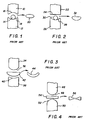
- the upper and lower mold halves 10, 12 compress a spherical glass preform 14 therebetween.
- the radius of the spherical glass preform 14 must be less than the radius of both of the concave mold surfaces 16, 18. As the glass preform 14 is compressed, the glass flows generally radially outwardly from the center of the mold cavity thereby expelling any gas from the mold cavity. This results in the production of a double convex lens 20 free from distortion due to trapped gas.
- Such molded lenses typically have accurate and repeatable surface replication relative to the mold.
- Figure 2 schematically depicts a prior art arrangement wherein the upper mold half 22 includes a plano mold surface 24 and the lower mold half 26 includes a concave mold surface 28.
- a spherical preform 30 just as with the arrangement depicted in Figure 1, but in this instance to produce a piano-convex optical element 32.
- Figure 3 looking at Figure 3 there is schematically depicted a prior art arrangement wherein the upper mold half 34 includes a convex mold surface 36 and the lower mold half 38 includes a concave mold surface 40.
- a plano-convex preform 42 to produce a concave-convex optical element 44.
- the radius of the convex surface of preform 42 must be less than the radius of concave mold surface 40. This ensures first contact between mold surface 40 and preform 42 substantially at the centerline of the mold apparatus thereby causing the preform to flow generally radially outwardly to prevent the trapping of gases.
- the first contact between convex mold surface 36 and the plano surface of preform 42 is substantially at the centerline of the mold apparatus thereby also causing the preform 42 to flow generally radially outwardly to prevent the trapping of gases.
- Figure 4 schematically depicts a prior art arrangement wherein the upper mold half 46 includes a convex mold surface 48 and the lower mold half 50 includes a convex mold surface 52.
- a piano-piano preform 54 to produce a double concave optical element 56.
- the plano-plano preform 54 ensures first contact between the mold surfaces 48, 52 and preform 54 substantially at the centerline of the mold apparatus thereby causing the preform to flow generally radially outwardly to prevent the trapping of gases. Examples of such practices are cited in U.S. 5,662,951 and 4,797,144. The method outlined in these patents works well for single cavity molds where one lens is molded from one preform.
- US Patent No. 5,276,538 indicates that an array of microlenses may be fabricated by pressing a piano preform between an upper plano mold surface and a lower mold surface with concave microlens cavities. This approach, however, will cause surface figure distortion of the microlens features due to trapped gas.
- Another method of forming an array of microlens is taught in US Patent No. 5,276,538 where micro-sized spherical preforms are placed in a plurality of cavities of the lower mold and many microlenses are molded simultaneously.
- this method would be cost prohibitive.
- the object of the present invention to provide a method and apparatus for compression molding an array of integrally formed glass lenses using a single preform.
- first mold half fabricating a second mold half with a central nest and a plurality of predetermined negative optical surface features therein; placing a glass preform in the central nest; heating the first and second mold halves and the glass preform to at least the glass transition temperature of the glass preform; pressing the glass preform between the first and second mold halves to thereby form an integral array of optical elements, each of the optical elements being a positive of the predetermined negative optical surface features; cooling the integral array of optical elements to below the glass transition temperature; and removing the integral array of optical elements from the first and second mold halves.
- the apparatus used for performing the method of the present invention comprises an upper mold half that is either plano or has microlens features; a lower mold half with microlens cavities and a central nest or depression for holding and aligning a cylindrical, spherical or oblate spheroid glass preform; and a means for heating the upper and lower mold halves and the preform.
- the depth, spacing, diameter, radial distance from the central nest, and relative location of the microlens features may affect the formation of bubbles in the microlenses.
- the central nest feature in the lower mold half allows the preform, such as a sphere, to rest in the proper location relative to the microlens cavities on the mold. Further, as the glass flows during the compression molding process, the glass expels gas from the mold cavities allowing the formation of lenses with accurate surface figure. Also, because only a single preform such as a sphere, oblate spheroid, or cylinder/fiber is required to mold many microlenses, this process is very efficient and cost effective.
- this method allows for the molding of may types of microlenses including, but not limited to, plano-convex, plano-concave, convex-convex, concave-convex, concave-concave, and lenses with aspheric, anamorphic, and diffractive features as well as gratings and diffractive phase plates (Damman gratings).
- microlenses including, but not limited to, plano-convex, plano-concave, convex-convex, concave-convex, concave-concave, and lenses with aspheric, anamorphic, and diffractive features as well as gratings and diffractive phase plates (Damman gratings).
- optical elements such as lenses may be generally distinguished from microoptical elements such as microlenses in terms of diameter.
- Optical elements such as lenses as have a diameter of at least 1mm while microoptical elements such as microlenses have a diameter of less than 1mm.
- the method and apparatus of the present invention may be used to produce both optical elements and microoptical elements.
- optical elements is intended to include any optical elements regardless of whether they have a diameter which is greater than or equal to 1mm, or less than 1mm.
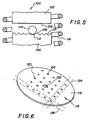
- the apparatus 100 of the present invention includes an upper mold half 102 in the lower mold half 104.
- the upper mold half 102 includes an upper mold surface 106.
- Upper mold surface 106 is depicted as being piano but may include other optical geometries of such as concave or convex features.
- the lower mold half 104 includes mold surface 108 which has formed therein a plurality of lens or micro-lens cavities 110.
- the lens or micro-lens cavities 110 are spaced apart from a central nesting cavity 112 which provides residence for a preform 114 which is depicted as being spherical.
- induction heating coil 116 Surrounding upper and lower mold halves 102 and 104 is induction heating coil 116.
- a preform 114 is placed in central nest cavity 112 and through actuation of induction heating coil 116, the temperature of the upper and lower more halves 102, 104 and preform 114 is raised to at least the glass transition temperature of the preform 114. Then the preform 114 is pressed between the upper and lower mold halves 102, 104 causing the preform 114 to deform and flow generally radially outward as depicted in Figure 7. As the preform flows radially outward, it fills the lens or micro-lens cavities 110.
- upper and lower mold halves 102, 104 are not necessarily directly heated by induction. Rather, upper and lower mold halves 102, 104 preferably reside in a mold body (not shown) fabricated from a conductive material such as graphite or molybdenum. The mold body is heated by the induction field and the upper and lower mold halves 102, 104 are heated indirectly by conduction and radiant heat transfer.
- Microlens arrays 118 such as shown in Figure 6, for example, molded in accordance with the method of the present invention are free from surface figure distortion.
- Such a microlens array 118 includes a glass web 119 having microoptical elements such as microlenses 120 projecting therefrom.
- the central "bump" 122 created in the central cavity 112, however, is likely to have a gas void at the vertex.
- the central "bump" 122 is discarded.
- Dashed lines 124 denote exemplary singulation cuts which may be made using a single or ganged blade dicing saw.
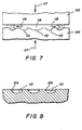
- Central nest 112 is used to hold the preform 114 during molding. As shown in Figure 7, by using a larger central "nest" or cavity 112 in the lower mold half 104 to hold the glass ball preform 114, it is possible to control the flow of the glass preform 114.
- the glass preform 114 flows generally radially outwardly as indicated by arrows 115 when mold halves 102, 104 compress preform 114 as indicated by arrows 117. In such manner, the glass flows into and across each microlens cavity 110 so that as the glass fills each microlens cavity 110 the air is expelled.
- the cavities 110 were formed in the mold half 104 using a spherical penetrator 1.5875 mm in diameter.
- An array 118 of microlenses 120 was molded from TaC4 glass (Hoya Optics) at a temperature of 735°C in a nitrogen atmosphere.
- the starting glass ball preform 114 had a diameter of 2.16 mm.
- the preform 114 was placed in the central nest 112 and the mold halves 102, 104 were inductively heated. After suitable heating time, the mold halves 102, 104 were brought together compressing the glass preform 115 into its final molded shape.
- the lens array 118 had four spherical microlenses 120 (each being 440 ⁇ m in diameter by 31 ⁇ m vertex height) integrally molded to a glass web.
- the lenses 120 were located at 90° positions about the center of the tool and were radially located 1.5 mm from the center.
- the "bump" formed by the central nest was 1.4 mm in diameter by 419.5 ⁇ m deep. Microlenses 120 molded in such an array 118 were found to be free from voids due to trapped gasses.
- the central "bump" 122 did have a void due to trapped gas.
- an array 118 of eight microlenses 120 was molded using a lower mold half 104 with a central nest 112 to hold the preform 114 similar to the arrangement shown in Figure 5.
- the lower mold half 104 contained the microlens cavities 110 as well as the central nest 112.
- the upper mold half 102 had a flat (plano) mold surface 106.
- the upper and lower mold halves 102, 104 were constructed from thoriated tungsten.
- a layered coating consisting of a base layer of 750 ⁇ of tantalum, an intermediate layer of 1500 ⁇ of SiC, and a final layer of 1500 ⁇ of hard carbon was applied to the mold surfaces 106, 108 of the tool to minimize thermal etching of the tungsten and to aid in release of the glass from the tool.
- the microlens cavities 110 and the central nest 112 were formed in the lower mold half 104.
- a microimpression technique was used to create the microlens cavities 110 and the central nest 112.
- those skilled in the art will recognize that a variety of different techniques may be used to form the microlens cavities 110 and the central nest 112. For example, such cavities could be formed by diamond turning or reactive ion etching.
- An array 118 of eight microlenses 120 was molded from TaC4 glass (Hoya Optics) at a temperature of 720°C (glass viscosity of 10 6.63 P) in a nitrogen atmosphere.
- the starting glass ball preform 114 was 2.80 mm in diameter and was placed in the central nest 112 of the lower mold 104.
- the mold halves 102, 104 were inductively heated, and after suitable heating time to raise the temperature of the mold halves 102, 104 and the preform 114 to 720°C, the mold halves 102, 104 were brought together compressing the glass preform 114 into its final molded shape.
- the molded lens array 118 was comprised of a glass web 50 um thick with eight radially located microlenses 45° apart and 3.5 mm from the center.
- the microlenses 120 were 240 um in diameter with a vertex height of 60 um. In conducting this experiment, a force of 250 lbf and a viscosity of 10 6.63 P was used to successfully mold an array 118.
- the viscosity, molding force, compression rate, microlens mold geometry, location of the microlens cavities relative to the initial location of the perform, and the sag of the microlens mold will affect the propensity for void formation by stagnation, that is, the trapping of gas in individual cavities 110.
- Those skilled in the art will recognize that one or more of these factors can be varied to empirically arrive at a process configuration for a particular lens or microlens array design.
- One approach to determine the proper operating conditions for molding microlens arrays is to fabricate a special mold with an array of microlens cavities that vary in sag depth and radius of curvature. A design of experiments may then be conducted where glass viscosity, molding force, and molding time are varied.
- the data may then be tabulated to determine the limits for void-free molded microlenses. It is also possible to conduct partial filling studies (short shot) by molding intermediate arrays (interrupt the molding process before the mold halves are completely closed) in order to develop an understanding of filling patterns.
- Equation 2 may be used to estimate the load and viscosity required to achieve specific mold compression rates.
- arrays of integrally formed microlenses can be molded using a lower mold half 130 (see Figure 9) including microlens cavities (predetermined negative optical surface features) 132 and a central nest 134 wherein the central nest 134 is adapted to receive a cylindrical or fiber-shaped preform.
- An exemplary array 138 molded with this mold configuration is depicted in Figure 10.
- Such exemplary array includes optical elements or lenses 140 which are positives of the predetermined negative optical surface features 132.
- the "bump" 142 formed in the central nest area is generally cylindrical in shape.
- Dashed lines 144 indicate representative cut lines for lens singulation.
- a hard carbon coating is adequate for use as a release agent.
- a variety of carbon coating release agents are known in the prior art
- the preferred method of carbon coating is the pyrolysis of simple hydrocarbon gases such as methane or acetylene. Additional methods are known in the prior art which are alleged to produce a diamond-like carbon. It is preferred to place the release agent on the tool rather than on the preform because the preform surface is remapped during the pressing operation. When the molding process is performed correctly, the curvature of the preform will always be greater than the curvature of the mold surface. In this way, the finished lens will always have a greater surface area then the surface of the preform from which it was made. It is also possible to coat both the preform and the tool with a carbon coating.
- glass preforms described herein have generally spherical or cylindrical geometries, those skilled in the art with recognize that other geometries may be useful depending on the final shape to be achieved for a particular lens or optical element.
- central nest feature is described herein as preferably being a depression in the mold surface, the critical function is that the preform be centered within an array of predetermined negative optical surface features.
- This central nesting could be similarly accomplished by providing a generally spherical preform including a small flat thereon allowing the preform to rest in a stable position on a flat central nest area of the lower mold surface.
- Other potential central nesting means include a gas jet that centers a spherical preform, or, small arms or guides that hold the preform until the mold halves engage the preform.
- the heater described with reference to Figure 5 is an induction-type heater. Heating could also be performed using other types of heaters such as, for example, radiant heaters, resistance heaters, infrared heaters, halogen heaters, etc.
Landscapes
- Engineering & Computer Science (AREA)
- Chemical & Material Sciences (AREA)
- Manufacturing & Machinery (AREA)
- Materials Engineering (AREA)
- Organic Chemistry (AREA)
- Moulds For Moulding Plastics Or The Like (AREA)
- Casting Or Compression Moulding Of Plastics Or The Like (AREA)
Applications Claiming Priority (2)
| Application Number | Priority Date | Filing Date | Title |
|---|---|---|---|
| US354219 | 1999-07-15 | ||
| US09/354,219 US6305194B1 (en) | 1999-07-15 | 1999-07-15 | Mold and compression molding method for microlens arrays |
Publications (2)
| Publication Number | Publication Date |
|---|---|
| EP1069082A2 true EP1069082A2 (fr) | 2001-01-17 |
| EP1069082A3 EP1069082A3 (fr) | 2001-10-17 |
Family
ID=23392360
Family Applications (1)
| Application Number | Title | Priority Date | Filing Date |
|---|---|---|---|
| EP00202332A Withdrawn EP1069082A3 (fr) | 1999-07-15 | 2000-07-03 | Procédé et dispositif de mouler par compression des matices de lentilles en verre |
Country Status (3)
| Country | Link |
|---|---|
| US (1) | US6305194B1 (fr) |
| EP (1) | EP1069082A3 (fr) |
| JP (1) | JP2001048554A (fr) |
Cited By (5)
| Publication number | Priority date | Publication date | Assignee | Title |
|---|---|---|---|---|
| EP1153893A3 (fr) * | 2000-05-12 | 2002-05-22 | Eastman Kodak Company | Procédé de fabrication d' un outil pour le moulage de matrices de microlentilles |
| US6597510B2 (en) | 2001-11-02 | 2003-07-22 | Corning Incorporated | Methods and apparatus for making optical devices including microlens arrays |
| EP1329432A1 (fr) * | 2002-01-18 | 2003-07-23 | Nippon Sheet Glass Co., Ltd. | Procédé de fabrication d'une structure asphérique, moule pour réseaux de lentilles asphériques et réseau de lentilles asphériques produits par ce procédé |
| EP1394123A1 (fr) * | 2002-08-29 | 2004-03-03 | Eastman Kodak Company | Procédé de moulage de lentilles en verre utilisant un moule traité par implantation ionique |
| WO2004039736A1 (fr) * | 2002-10-29 | 2004-05-13 | Corning Incorporated | Fabrication basse temperature de composants optiques en verre |
Families Citing this family (24)
| Publication number | Priority date | Publication date | Assignee | Title |
|---|---|---|---|---|
| JP3900693B2 (ja) * | 1998-07-17 | 2007-04-04 | ソニー株式会社 | レンズ製造方法 |
| DE19956654B4 (de) * | 1999-11-25 | 2005-04-21 | Fraunhofer-Gesellschaft zur Förderung der angewandten Forschung e.V. | Verfahren zur Strukturierung von Oberflächen von mikromechanischen und/oder mikrooptischen Bauelementen und/oder Funktionselementen aus glasartigen Materialien |
| US6491481B1 (en) * | 2000-10-31 | 2002-12-10 | Eastman Kodak Company | Method of making a precision microlens mold and a microlens mold |
| US7013676B2 (en) * | 2001-08-10 | 2006-03-21 | Hoya Corporation | Press molding apparatus |
| US6624948B1 (en) | 2001-12-21 | 2003-09-23 | Eastman Kodak Company | Method of forming precision glass microlens arrays and a microlens array formed therewith |
| US7736550B2 (en) * | 2002-02-13 | 2010-06-15 | Anteryon B.V. | Method of manufacturing an optical device by means of a replication method |
| JP4194809B2 (ja) * | 2002-08-21 | 2008-12-10 | フジノン株式会社 | マイクロレンズアレイの成形装置 |
| EP1443344A1 (fr) * | 2003-01-29 | 2004-08-04 | Heptagon Oy | Production d'éléments à microstructure |
| DE10313889B3 (de) * | 2003-03-27 | 2004-08-26 | Fraunhofer-Gesellschaft zur Förderung der angewandten Forschung e.V. | Verfahren zur Herstellung einzelner Mikrolinsen oder eines Mikrolinsenarrays |
| US7715105B2 (en) * | 2003-09-10 | 2010-05-11 | Precision Optics Corporation | Acylindrical optical device |
| DE102004021215C5 (de) * | 2004-04-29 | 2014-10-30 | Schott Ag | Verfahren zum Ausbilden eines optischen Elements |
| JP5017798B2 (ja) * | 2005-04-20 | 2012-09-05 | コニカミノルタアドバンストレイヤー株式会社 | ピックアップ光学系に用いられる整形素子を成形する成形装置および該装置により製造された整形素子 |
| ATE477220T1 (de) * | 2007-02-28 | 2010-08-15 | Corning Inc | Verfahren zur herstellung von mikrofluidischen vorrichtungen |
| KR20140041937A (ko) | 2007-06-20 | 2014-04-04 | 쓰리엠 이노베이티브 프로퍼티즈 컴파니 | 웨브 상에서의 초음파 사출 성형 |
| CN101571604A (zh) * | 2008-04-28 | 2009-11-04 | 鸿富锦精密工业(深圳)有限公司 | 双面镜片制作方法 |
| US9981844B2 (en) | 2012-03-08 | 2018-05-29 | Infineon Technologies Ag | Method of manufacturing semiconductor device with glass pieces |
| US10481303B2 (en) | 2012-09-15 | 2019-11-19 | Konica Minolta, Inc. | Lens array, lens array laminate body , lens array manufacturing method, lens array laminate body manufacturing method, and lens unit manufacturing method |
| KR101597520B1 (ko) * | 2014-11-10 | 2016-02-25 | 엠피닉스 주식회사 | 광학렌즈 성형용 금형의 제조방법, 상기 제조방법으로 제조된 광학렌즈 성형용 금형 및 상기 금형을 이용한 광학렌즈 제조방법 |
| US10969560B2 (en) | 2017-05-04 | 2021-04-06 | Lightpath Technologies, Inc. | Integrated optical assembly and manufacturing the same |
| TWI774854B (zh) | 2017-10-13 | 2022-08-21 | 美商康寧公司 | 用於壓製玻璃或玻璃陶瓷預製件以形成成形板的方法與設備、製造液體透鏡的方法及液體透鏡 |
| KR102193774B1 (ko) | 2019-05-24 | 2020-12-22 | 엠피닉스 주식회사 | 광학용 멀티플렉서의 제조방법 및 광학용 멀티플레서 |
| EP4402116A4 (fr) * | 2021-09-14 | 2025-08-20 | Univ Northeastern | Matériau céramique thermoformable à base de bore et son utilisation dans la gestion thermique |
| CN218620605U (zh) * | 2022-06-01 | 2023-03-14 | 常州市瑞泰光电有限公司 | 玻璃产品的成型模具 |
| CN116924662A (zh) * | 2023-07-28 | 2023-10-24 | 无锡市锡山区半导体先进制造创新中心 | 一种模压成形方法 |
Family Cites Families (20)
| Publication number | Priority date | Publication date | Assignee | Title |
|---|---|---|---|---|
| US3833347A (en) | 1970-11-27 | 1974-09-03 | Eastman Kodak Co | Method for molding glass lenses |
| US4168961A (en) | 1975-09-02 | 1979-09-25 | Eastman Kodak Company | Method of molding glass elements |
| CA1081958A (fr) | 1975-09-02 | 1980-07-22 | Gerald E. Blair | Methode de moulage d'elements en verre |
| US4243618A (en) | 1978-10-23 | 1981-01-06 | Avery International Corporation | Method for forming retroreflective sheeting |
| JPS60118639A (ja) | 1983-11-29 | 1985-06-26 | Hoya Corp | プレスレンズの製造方法 |
| US4797144A (en) | 1987-07-20 | 1989-01-10 | Corning Glass Works | Deep pressing mold and process for molded optical elements |
| JPH0244033A (ja) * | 1988-08-04 | 1990-02-14 | Matsushita Electric Ind Co Ltd | レンズ加工装置およびレンズ |
| JPH02149436A (ja) * | 1988-11-30 | 1990-06-08 | Matsushita Electric Ind Co Ltd | 多数個取り凹レンズ成形金型 |
| EP0450780A3 (en) * | 1990-04-05 | 1992-04-15 | Matsushita Electric Industrial Co., Ltd. | Optical microelement array and its production method |
| US5298366A (en) | 1990-10-09 | 1994-03-29 | Brother Kogyo Kabushiki Kaisha | Method for producing a microlens array |
| GB2264890A (en) * | 1991-12-11 | 1993-09-15 | British Telecomm | Moulding of lenses and lenticular sheets |
| JPH0634805A (ja) * | 1992-07-21 | 1994-02-10 | Matsushita Electric Ind Co Ltd | 回折格子のプレス成形用型及びその作製方法ならびに回折格子の作製方法 |
| US5368790A (en) | 1992-08-19 | 1994-11-29 | Greshes; Martin | Method for making lenses |
| JP3266659B2 (ja) * | 1992-09-11 | 2002-03-18 | 旭光学工業株式会社 | 光学素子成形用の成形型及び光学素子の成形方法 |
| US5300263A (en) | 1992-10-28 | 1994-04-05 | Minnesota Mining And Manufacturing Company | Method of making a microlens array and mold |
| JPH07149528A (ja) * | 1993-11-30 | 1995-06-13 | Matsushita Electric Ind Co Ltd | マイクロレンズアレイの成形用型及びその製造方法並びにマイクロレンズの製造方法 |
| US5536455A (en) | 1994-01-03 | 1996-07-16 | Omron Corporation | Method of manufacturing lens array |
| US5507806A (en) | 1994-05-13 | 1996-04-16 | Pharmacia Iovision, Inc. | Multi-faceted intraocular lens |
| FR2722303B1 (fr) * | 1994-07-07 | 1996-09-06 | Corning Inc | Procede et dispositif de fabrication de reseaux de microlentilles optiques |
| JPH10142404A (ja) * | 1996-11-07 | 1998-05-29 | Sony Corp | ガラス製の光学ピックアップ用マルチレンズ及びその製造方法 |
-
1999
- 1999-07-15 US US09/354,219 patent/US6305194B1/en not_active Expired - Lifetime
-
2000
- 2000-07-03 EP EP00202332A patent/EP1069082A3/fr not_active Withdrawn
- 2000-07-14 JP JP2000214603A patent/JP2001048554A/ja active Pending
Cited By (7)
| Publication number | Priority date | Publication date | Assignee | Title |
|---|---|---|---|---|
| EP1153893A3 (fr) * | 2000-05-12 | 2002-05-22 | Eastman Kodak Company | Procédé de fabrication d' un outil pour le moulage de matrices de microlentilles |
| US6597510B2 (en) | 2001-11-02 | 2003-07-22 | Corning Incorporated | Methods and apparatus for making optical devices including microlens arrays |
| EP1329432A1 (fr) * | 2002-01-18 | 2003-07-23 | Nippon Sheet Glass Co., Ltd. | Procédé de fabrication d'une structure asphérique, moule pour réseaux de lentilles asphériques et réseau de lentilles asphériques produits par ce procédé |
| US7329372B2 (en) | 2002-01-18 | 2008-02-12 | Nippon Sheet Glass Co., Ltd. | Method for producing aspherical structure, and aspherical lens array molding tool and aspherical lens array produced by the same method |
| EP1394123A1 (fr) * | 2002-08-29 | 2004-03-03 | Eastman Kodak Company | Procédé de moulage de lentilles en verre utilisant un moule traité par implantation ionique |
| WO2004039736A1 (fr) * | 2002-10-29 | 2004-05-13 | Corning Incorporated | Fabrication basse temperature de composants optiques en verre |
| US7143609B2 (en) | 2002-10-29 | 2006-12-05 | Corning Incorporated | Low-temperature fabrication of glass optical components |
Also Published As
| Publication number | Publication date |
|---|---|
| JP2001048554A (ja) | 2001-02-20 |
| EP1069082A3 (fr) | 2001-10-17 |
| US6305194B1 (en) | 2001-10-23 |
Similar Documents
| Publication | Publication Date | Title |
|---|---|---|
| US6305194B1 (en) | Mold and compression molding method for microlens arrays | |
| US9242889B2 (en) | Method of manufacturing formed article, glass material, and method of determining shape of glass material and mold | |
| CN101321700B (zh) | 成形品的制造方法、密封部件以及包括其的成形装置 | |
| US6567223B2 (en) | Molded lens element having a two-dimensional reference molded therein | |
| JPH09132417A (ja) | ガラス光学素子の成形方法 | |
| CN101304953A (zh) | 光学元件的成形方法及成形装置 | |
| JP5200074B2 (ja) | モールドプレス成形装置及び光学素子の製造方法 | |
| JP4709137B2 (ja) | 個々のマイクロレンズまたはマイクロレンズアレイを製造するための方法 | |
| US6385997B1 (en) | Method for forming a tool for molding microlens arrays | |
| JP4951166B2 (ja) | レンズブランク及びレンズの製造方法 | |
| JP7066533B2 (ja) | ガラスレンズ成形型 | |
| CN101321701B (zh) | 成形品的制造方法、保持部件及成形装置 | |
| US10850461B2 (en) | Method of manufacturing contact lenses | |
| TWI774854B (zh) | 用於壓製玻璃或玻璃陶瓷預製件以形成成形板的方法與設備、製造液體透鏡的方法及液體透鏡 | |
| US6476973B1 (en) | Compound surface to aid in the fabrication of a lens with a plano surface | |
| EP1231187A1 (fr) | Appareil et méthode pour le moulage d'éléments optiques en verre | |
| JP7286836B2 (ja) | ガラスレンズ成形型 | |
| JP5445087B2 (ja) | 光学素子用成形型及び光学素子の成形方法 | |
| JP2006001803A (ja) | モールドプレス成形型、光学素子の製造方法、及びモールドプレスレンズ | |
| JPH02293335A (ja) | 光学素子の成形方法及び成形装置 | |
| JP2007099529A (ja) | 精密プレス成形用プリフォームおよびその製造方法ならびに光学素子の製造方法 | |
| JP2009096648A (ja) | レンズアレイの製造方法 | |
| JPH0686301B2 (ja) | 光学素子の加圧成形方法 | |
| TW202432483A (zh) | 沖壓成形裝置和方法、玻璃透鏡坯料、玻璃透鏡及其製造方法 | |
| JPH11180721A (ja) | モールド成形用金型 |
Legal Events
| Date | Code | Title | Description |
|---|---|---|---|
| PUAI | Public reference made under article 153(3) epc to a published international application that has entered the european phase |
Free format text: ORIGINAL CODE: 0009012 |
|
| AK | Designated contracting states |
Kind code of ref document: A2 Designated state(s): AT BE CH CY DE DK ES FI FR GB GR IE IT LI LU MC NL PT SE Kind code of ref document: A2 Designated state(s): DE FR GB NL |
|
| AX | Request for extension of the european patent |
Free format text: AL;LT;LV;MK;RO;SI |
|
| PUAL | Search report despatched |
Free format text: ORIGINAL CODE: 0009013 |
|
| AK | Designated contracting states |
Kind code of ref document: A3 Designated state(s): AT BE CH CY DE DK ES FI FR GB GR IE IT LI LU MC NL PT SE |
|
| AX | Request for extension of the european patent |
Free format text: AL;LT;LV;MK;RO;SI |
|
| 17P | Request for examination filed |
Effective date: 20020314 |
|
| AKX | Designation fees paid |
Free format text: DE FR GB NL |
|
| 17Q | First examination report despatched |
Effective date: 20040226 |
|
| GRAP | Despatch of communication of intention to grant a patent |
Free format text: ORIGINAL CODE: EPIDOSNIGR1 |
|
| STAA | Information on the status of an ep patent application or granted ep patent |
Free format text: STATUS: THE APPLICATION IS DEEMED TO BE WITHDRAWN |
|
| 18D | Application deemed to be withdrawn |
Effective date: 20050826 |