EP1069004B1 - Überzuganordnung zur Aufnahme eines Airbags - Google Patents
Überzuganordnung zur Aufnahme eines Airbags Download PDFInfo
- Publication number
- EP1069004B1 EP1069004B1 EP00115317A EP00115317A EP1069004B1 EP 1069004 B1 EP1069004 B1 EP 1069004B1 EP 00115317 A EP00115317 A EP 00115317A EP 00115317 A EP00115317 A EP 00115317A EP 1069004 B1 EP1069004 B1 EP 1069004B1
- Authority
- EP
- European Patent Office
- Prior art keywords
- section
- trim
- margin
- liner
- seam
- Prior art date
- Legal status (The legal status is an assumption and is not a legal conclusion. Google has not performed a legal analysis and makes no representation as to the accuracy of the status listed.)
- Expired - Lifetime
Links
- 230000035515 penetration Effects 0.000 claims abstract description 12
- 238000000034 method Methods 0.000 claims description 15
- 238000004519 manufacturing process Methods 0.000 claims description 2
- 230000000903 blocking effect Effects 0.000 abstract description 2
- 239000000853 adhesive Substances 0.000 description 3
- 230000001070 adhesive effect Effects 0.000 description 3
- 239000000463 material Substances 0.000 description 3
- 239000011248 coating agent Substances 0.000 description 2
- 238000000576 coating method Methods 0.000 description 2
- 239000004744 fabric Substances 0.000 description 2
- 239000004677 Nylon Substances 0.000 description 1
- 230000002411 adverse Effects 0.000 description 1
- 238000007796 conventional method Methods 0.000 description 1
- 238000011161 development Methods 0.000 description 1
- 230000018109 developmental process Effects 0.000 description 1
- 239000013013 elastic material Substances 0.000 description 1
- 239000010985 leather Substances 0.000 description 1
- 229920001778 nylon Polymers 0.000 description 1
- 229920000728 polyester Polymers 0.000 description 1
- 125000000391 vinyl group Chemical group [H]C([*])=C([H])[H] 0.000 description 1
- 229920002554 vinyl polymer Polymers 0.000 description 1
Images


Classifications
-
- B—PERFORMING OPERATIONS; TRANSPORTING
- B60—VEHICLES IN GENERAL
- B60R—VEHICLES, VEHICLE FITTINGS, OR VEHICLE PARTS, NOT OTHERWISE PROVIDED FOR
- B60R21/00—Arrangements or fittings on vehicles for protecting or preventing injuries to occupants or pedestrians in case of accidents or other traffic risks
- B60R21/02—Occupant safety arrangements or fittings, e.g. crash pads
- B60R21/16—Inflatable occupant restraints or confinements designed to inflate upon impact or impending impact, e.g. air bags
- B60R21/20—Arrangements for storing inflatable members in their non-use or deflated condition; Arrangement or mounting of air bag modules or components
- B60R21/207—Arrangements for storing inflatable members in their non-use or deflated condition; Arrangement or mounting of air bag modules or components in vehicle seats
-
- B—PERFORMING OPERATIONS; TRANSPORTING
- B60—VEHICLES IN GENERAL
- B60R—VEHICLES, VEHICLE FITTINGS, OR VEHICLE PARTS, NOT OTHERWISE PROVIDED FOR
- B60R21/00—Arrangements or fittings on vehicles for protecting or preventing injuries to occupants or pedestrians in case of accidents or other traffic risks
- B60R21/02—Occupant safety arrangements or fittings, e.g. crash pads
- B60R21/16—Inflatable occupant restraints or confinements designed to inflate upon impact or impending impact, e.g. air bags
- B60R2021/161—Inflatable occupant restraints or confinements designed to inflate upon impact or impending impact, e.g. air bags characterised by additional means for controlling deployment trajectory
Definitions
- the invention relates generally to an assembly for housing an inflatable airbag. More particularly, the invention relates to an assembly that includes a cavity liner for directing the force of an inflatable airbag in a direction towards a particular seam in the trim cover, thereby directing deployment of the inflatable airbag through the particular seam.
- SIAB Seat mounted side impact inflatable airbags
- the first type of seat mounted SIABs deploys from a visible, discrete door on the outboard side of the seat back or seat cushion bolster.
- the other type of seat mounted SIABs is stowed beneath the seat trim and is designed to deploy through the trim cover.
- the first type has an advantage in that the technology for the deployment of an airbag through a discrete door has been already developed for frontal airbags in steering wheels and instrument panels.
- the first type has the disadvantage, however, in that the location of the SIAB is generally limited to the side of the seat so that the visible door is not a part of the seating surface engaged by a seat occupant. If it is desired for the airbag to deploy through the front corner of the seat back, such as the location of a bolster seam, the first type of seat mounted SIABs cannot be used. Rather, the second type of seat mounted SIABs must be used, typically under the trim cover and the foamed padding such that the airbag does not adversely affect the seat comfort.
- One of the recent developments for the second type of seat mounted side impact airbags includes the use of a cavity liner for directing the force of the airbag in a direction towards a particular seam.
- a cavity liner is typically topstitched into the trim cover for the seat back of the passenger seat.
- the front corner of the seat back is one of the most visible aspects of the passenger seat and a topstitch at the bolster seam is considered by prospective buyers of expensive automobiles as an aesthetically unpleas.
- the FR-A-2753425 discloses a vehicle component, capable of receiving an air bag and having a coating provided with a seam which can be tom off by inflating said air bag.
- the component comprises a pocket for receiving said air bag, said pocket being formed by panels that are connected to margin portions of the coating in order to direct the inflating airbag towards the seam.
- the invention provides an assembly for housing an inflatable airbag module that overcomes the problems and disadvantages of the conventional techniques in the art
- the present invention also provides for an assembly that offers an aesthetically pleasing housing for an inflatable airbag.
- the assembly of the invention includes a two-section trim cover for covering a component of a vehicle.
- the outer surfaces of the trim sections are secured to each other thereby forming a plain seam, with margin portions of the trim cover folded inward of the outer surfaces.
- the assembly further includes a two-section cavity liner for directing the force of the inflatable airbag in a direction toward the plain seam.
- the margin portions of the trim cover are secured to the liner sections.
- the margin portions of the trim cover are, however, secured to the liner sections without substantial penetration through the outer surfaces of the trim cover. For this reason, the assembly offers an aesthetically pleasing housing for an inflatable airbag as the stitching is substantially hidden from a vantage facing the outer surfaces of the trim cover.
- first and second preferred embodiments and the first and second preferred methods is merely exemplary in nature, and is in no way intended to limit the invention, or its applications, or uses.
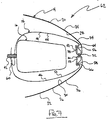
- the assembly 10 functions to cover an internal seat back frame of the passenger seat 12 and to house an inflatable airbag module hidden in the passenger seat 12 and attached to the seat back frame.
- the assembly 10 may be used to cover other components of a vehicle, for example, the dashboard, the headliner, the roof pillar, the console, or any other appropriate component.
- the assembly 10 of the first preferred embodiment of the invention includes a trim cover 14, an inflatable airbag module 16, and a cavity liner 18.
- the trim cover 14 includes a first trim section 20 and a second trim section 22. Both trim sections 20 and 22 have outer surfaces 24 and 26 that are made from a durable material such as leather, cloth, and vinyl, and inner surfaces 28 and 30 that are made from a softer material such as foamed padding.
- the first trim section 20 is secured to the second trim section 22 with a plain seam 32.
- the plain seam 32 is a conventional stitch or, alternatively, may be other fasteners, such as adhesive, snaps, staples, VELCRO®, and DUAL-LOCK®.
- the trim sections 20 and 22 fold inward and the outer surface 24 of the first trim section 20 contacts the outer surface 26 of the second trim section 22.
- the plain seam 32 divides the trim sections 20 and 22 into body portions 34 and 36 and margin portions 38 and 40. While the outer surfaces 24 and 26 of the body portions 34 and 36 are visible to the passengers of the vehicle, the inner surfaces 28 and 30 of the body portions 34 and 36 and the entirety of the margin portions 38 and 40 are hidden.
- the inflatable airbag module 16 functions to reduce the severity of a vehicular impact by quickly inflating an airbag (not shown) between a passenger of the vehicle and the surfaces of the vehicle.
- the inflatable airbag module 16 is a conventional side impact airbag module.
- the inflatable airbag module 16 connects to the seat back frame (not shown) by a fastener 42.
- the fastener 42 includes a stud and a nut, but as a person of ordinary skill in the art would appreciate, other suitable fasteners can be used.
- the inflatable airbag module 16 may be secured to a dashboard structural member, a roof portion, a roof pillar, or any other suitable structural element of the vehicle.
- Inflatable airbag modules are known and used in the art of inflatable airbag systems, and the implementation of the inflatable airbag module 16 into the assembly 10 would be readily understood by a person of ordinary skill in the art.
- the cavity liner 18 of the invention directs the force of the airbag in a direction toward the plain seam 32.
- the cavity liner 18 includes a first liner section 44 and a second liner section 46.
- the first liner section 44 is secured to the first trim section 20 at the plain seam 32
- the second liner section 46 is secured to the second trim section 22 at the plain seam 32.
- the plain seam 32 further divides the liner sections 44 and 46 into body portions 48 and 50 and margin portions 52 and 54.
- the margin portions 38, 40, 52, and 54 are secured to the body portions 48 and 50 of the cavity liner 18.
- the margin portion 52 of the first liner section 44 and the margin portion 38 of the first trim section 20 are secured to the body portion 48 of the first liner section 44 by a first margin seam 56.
- the margin portion 54 of the second liner section 46 and the margin portion 40 of the second trim section 22 are secured to the body portion 50 of the second liner section 46 by a second margin seam 58.
- the margin seams 56 and 58 like the plain seam 32, are a conventional stitch or, alternatively, may be other fasteners, such as adhesive, snaps, staples, VELCRO®, and DUAL-LOCK®.
- margin seams 56 and 58 do not penetrate through the outer surfaces 24 and 26 of the trim cover 14. In other words, the margin seams 56 and 58 are substantially hidden from a vantage facing the outer surfaces 24 and 26 of the trim cover 14. For this reason, the assembly 10 offers an aesthetically pleasing housing for an inflatable airbag.
- the first liner section 44 and the second liner section 46 are made from a substantially non-elastic material such as 420, 630, or 840 denier nylon or polyester airbag fabric, or from other suitable materials.
- a rear seam 60 secures the first liner section 44 and the second liner section 46 to each other.
- the first liner section 44 may be integrally formed with the second liner section 46 in a one-piece cavity liner (not shown).
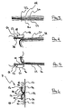
- the assembly 10 of the first preferred embodiment of the invention may be produced by the following four general steps: (1) providing a first trim section 20 and a second trim section 22, and providing a first liner section 44 and a second liner section 46; (2) stitching a plain seam 32 through the first liner section 44, the first trim section 20, the second trim section 22, and the second liner section 46, as shown in FIG. 3; (3) folding the body portion 48 of the first liner section 44 over the margin portion 52 of the first liner section 44, and stitching a first margin seam 56 through the body portion 48 of the first liner section 44 and the margin portion 38 of the first trim section 20, without substantial penetration through the body portion 34 of the first trim section 20 by the stitching, as shown in FIG.
- the assembly 10 may now house an inflatable airbag (not shown).
- steps 1 through 4 are followed in numerical order. In alternate methods, steps 1 through 4 may be followed in a different order.
- an assembly 62 of a second preferred embodiment of the invention includes a first minor tack 64 and a second minor tack 66.
- the minor tacks 64 and 66 function to secure the margin portions 38 and 40 of the trim cover 14 to the margin portions 52 and 54 of the cavity liner 18.
- the minor tacks 64 and 66 like the plain seam 32 and the margin seams 56 and 58, are a conventional stitch or, alternatively, may be other fasteners, such as adhesive, snaps, staples, VELCRO®, and DUAL-LOCK®.
- the assembly 62 of the second preferred embodiment functions like the assembly 10 of the first preferred embodiment. For this reason, the elements of FIG. 2 are shown with the same reference numerals of FIG. 7.
- the second preferred method which produces the assembly 62 of the second preferred embodiment, includes an additional step that occurs between step 1 and step 2 discussed above with respect to the first preferred method of the invention.
- the additional step includes stitching the first minor tack 64 through the margin portion 52 of the first liner section 44 and the margin portion 38 of the first trim section 20, as shown in FIG. 8.
- the additional step further includes stitching the second minor tack 66 through the margin portion 54 of the second liner section 46 and the margin portion 40 of the second trim section 22, as shown in FIG. 9.
- the additional step functions to align the margin portions 52 and 54 with the margin portions 38 and 40.
- steps 2, 3, and 4, as shown in FIGS. 10, 11, and 12 are like the steps 2, 3, and 4 shown in FIGS. 3, 4, and 5.
- the assembly 62 of the second preferred embodiment is like the assembly 10 of the first preferred embodiment shown in FIG. 6.
- the elements of FIGS. 8-13 are shown with the same reference numerals of FIGS. 3-6.
Landscapes
- Engineering & Computer Science (AREA)
- Mechanical Engineering (AREA)
- Air Bags (AREA)
- Seats For Vehicles (AREA)
Claims (15)
- Aufbau zur Aufnahme eines aufblasbaren Airbags, umfassend:einen Dekorbezug (14) zum Abdecken einer Komponente eines Fahrzeugs, wobei der Dekorbezug (14) einen ersten Dekorbezugsbereich (20) und einen zweiten Dekorbezugsbereich (22) aufweist, wobei der erste Dekorbezugsbereich (20) eine Außenoberfläche (24) und eine Innenoberfläche (28) aufweist, und wobei der zweite Dekorbezugsbereich (22) eine Außenoberfläche (26) und eine Innenoberfläche (30) aufweist, wobei die Außenoberfläche (24) des ersten Dekorbezugsbereichs (20) an der Außenoberfläche (26) des zweiten Dekorbezugsbereichs (22) gesichert ist und so eine flache Naht (32) bildet, wobei die flache Naht (32) einen Grundkörperabschnitt (34) und einen Randabschnitt (38) des ersten Dekorbezugsbereichs (20) definiert, und wobei die flache Naht (32) einen Grundkörperabschnitt (36) und einen Randabschnitt (40) des zweiten Dekorbezugsbereichs (22) definiert, sowie eine Hohlraumauskleidung (18) zur Leitung der Kraft des aufblasbaren Airbags (16) in Richtung der flachen Naht (32), wobei die Hohlraumauskleidung (18) einen ersten Auskleidungsbereich (44) und einen zweiten Auskleidungsbereich (46) aufweist,
dadurch gekennzeichnet, dassder erste Auskleidungsbereich (44) an der flachen Naht (32) am ersten Dekorbezugsbereich (20) gesichert ist, wobei die flache Naht (32) einen Grundkörperabschnitt (48) und einen Randabschnitt (52) des ersten Auskleidungsbereichs (44) definiert, und wobei der zweite Auskleidungsbereich (46) an der flachen Naht (32) am zweiten Dekorbezugsbereich (22) gesichert ist, wobei die flache Naht (32) einen Grundkörperabschnitt (50) und einen Randabschnitt (54) des zweiten Auskleidungsbereichs (46) definiert,
und wobei der Randabschnitt (38) des ersten Dekorbezugsbereichs (20) am Grundkörperabschnitt (48) des ersten Auskleidungsbereichs (44) ohne wesentliche Durchdringung der Außenoberfläche (24) des Grundkörperabschnitts (34) des ersten Dekorbezugsbereichs (20) gesichert ist, und wobei der Randabschnitt (40) des zweiten Dekorbezugsbereichs (22) am Grundkörperabschnitt (50) des zweiten Auskleidungsbereichs (46) ohne wesentliche Durchdringung der Außenoberfläche (26) des Grundkörperabschnitts (36) des zweiten Dekorbezugsbereichs (22) gesichert ist. - Aufbau nach Anspruch 1, gekennzeichnet durch einen aufblasbaren Airbag und dadurch, dass der Randabschnitt (38) des ersten Dekorbezugsbereichs (20) am Randabschnitt (52) des ersten Auskleidungsbereichs (44) an einer ersten kleinen Zwecke (64) gesichert ist, wobei der Randabschnitt (40) des zweiten Dekorbezugsbereichs (22) am Randabschnitt (54) des zweiten Auskleidungsbereichs (46) an einer zweiten kleinen Zwecke (66) gesichert ist, wobei der Randabschnitt (38) des ersten Dekorbezugsbereichs (20) am Grundkörperabschnitt (48) des ersten Auskleidungsbereichs (44) zwischen der ersten kleinen Zwecke (64) und der flachen Naht (32) gesichert ist und so eine erste Randnaht (56) ohne wesentliche Durchdringung der Außenoberfläche (24) des Grundkörperabschnitts (34) des ersten Dekorbezugsbereichs (20) bildet, und wobei der Randabschnitt (40) des zweiten Dekorbezugsbereichs (22) am Grundkörperabschnitt (50) des zweiten Auskleidungsbereichs (46) zwischen der zweiten kleinen Zwecke (66) und der flachen Naht (32) gesichert ist und so eine zweite Randnaht (58) ohne wesentliche Durchdringung der Außenoberfläche (26) des Grundkörperabschnitts (36) des zweiten Dekorbezugsbereichs (22) bildet.
- Aufbau nach Anspruch 1, dadurch gekennzeichnet, dass der Randabschnitt (38) des ersten Dekorbezugsbereichs (20) am Grundkörperabschnitt (48) des ersten Auskleidungsbereichs (44) gesichert ist und so eine erste Randnaht (56) bildet, wobei der Randabschnitt (40) des zweiten Dekorbezugsbereichs (22) am Grundkörperabschnitt (50) des zweiten Auskleidungsbereichs (46) gesichert ist und so eine zweite Randnaht (58) bildet.
- Aufbau nach Anspruch 3, dadurch gekennzeichnet, dass der Randabschnitt (38) des ersten Dekorbezugsbereichs (20) zusätzlich am Randabschnitt (52) des ersten Auskleidungsbereichs (44) gesichert ist, wobei der Randabschnitt (40) des zweiten Dekorbezugsbereichs (22) zusätzlich am Randabschnitt (54) des zweiten Auskleidungsbereichs (46) gesichert ist.
- Aufbau nach Anspruch 4, dadurch gekennzeichnet, dass der Randabschnitt (38) des ersten Dekorbezugsbereichs (20) am Randabschnitt (52) des ersten Auskleidungsbereichs (44) an der ersten Randnaht (56) gesichert ist, wobei der Randabschnitt (40) des zweiten Dekorbezugsbereichs (22) am Randabschnitt (54) des zweiten Auskleidungsbereichs (46) an der zweiten Randnaht (58) gesichert ist.
- Aufbau nach Anspruch 4, dadurch gekennzeichnet, dass der Randabschnitt (38) des ersten Dekorbezugsbereichs (20) am Randabschnitt (52) des ersten Auskleidungsbereichs (44) an einer ersten kleinen Zwecke (64) gesichert ist, wobei der Randabschnitt (40) des zweiten Dekorbezugsabschnitts (22) am Randabschnitt (54) des zweiten Auskleidungsbereichs (46) an einer zweiten kleinen Zwecke (66) gesichert ist.
- Aufbau nach Anspruch 6, dadurch gekennzeichnet, dass die erste Randnaht (56) am ersten Auskleidungsbereich (44) zwischen der ersten kleinen Zwecke (64) und der flachen Naht (32) angeordnet ist, wobei die zweite Randnaht (58) am zweiten Auskleidungsbereich (46) zwischen der zweiten kleinen Zwecke (66) und der flachen Naht (32) angeordnet ist.
- Aufbau nach Anspruch 1, dadurch gekennzeichnet, dass der erste Auskleidungsbereich (44) an der Innenoberfläche (28) des ersten Dekorbezugsbereichs (20) an der flachen Naht (32) gesichert ist, wobei der zweite Auskleidungsbereich (46) an der Innenoberfläche (30) des zweiten Dekorbezugsbereichs (22) an der flachen Naht (32) gesichert ist.
- Verfahren zum Herstellen eines Aufbaus zur Aufnahme eines aufblasbaren Airbags (16), die Schritte umfassend:(a) Anordnen eines Dekorbezugs (14), der einen ersten Dekorbezugsbereich (20) und einen zweiten Dekorbezugsbereich (22) aufweist, und Anordnen einer Hohlraumauskleidung (18), die einen ersten Auskleidungsbereich (44) und einen zweiten Auskleidungsbereich (46) aufweist, und(b) Vernähen einer flachen (32) durch den ersten Auskleidungsbereich (44), den ersten Dekorbezugsbereich (20), den zweiten Dekorbezugsbereich (22) und den zweiten Auskleidungsbereich (46), wobei die flache Naht (32) Grundkörperabschnitte (48) und Randabschnitte (52) des ersten Auskleidungsbereichs (44), des ersten Dekorbezugsbereichs (20), des zweiten Dekorbezugsbereichs (22) und des zweiten Auskleidungsbereichs (46) definiert, und(c) Falten des Grundkörperabschnitts (48) des ersten Auskleidungsbereichs (44) über den Randabschnitt (52) des ersten Auskleidungsbereichs (44) und Vernähen einer ersten Randnaht (56) durch den Grundkörperabschnitt (48) des ersten Auskleidungsbereichs (44) und des Randabschnitts (38) des ersten Dekorbezugsbereichs (20) ohne wesentliche Durchdringung des Grundkörperabschnitts (34) des ersten Dekorbezugsbereichs (20), und(d) Falten des Grundkörperabschnitts (50) des zweiten Auskleidungsbereichs (46) über den Randabschnitt (54) des zweiten Auskleidungsbereichs (46) und Vernähen einer zweiten Randnaht (58) durch den Grundkörperabschnitt (50) des zweiten Auskleidungsbereichs (46) und den Randabschnitt (40) des zweiten Dekorbezugsbereichs (22) ohne wesentliche Durchdringung des Grundkörperabschnitts (36) des zweiten Dekorbezugsbereichs (22).
- Verfahren nach Anspruch 9, dadurch gekennzeichnet, dass Schritt (b) vor den Schritten (c) und (d) stattfindet.
- Verfahren nach Anspruch 9, dadurch gekennzeichnet, dass Schritt (c) das Vernähen einer ersten Randnaht (56) durch den Grundkörperabschnitt (48) des ersten Auskleidungsbereichs (44), den Randabschnitt (52) des ersten Auskleidungsbereichs (44) und den Randabschnitt (38) des ersten Dekorbezugsbereichs (20) ohne wesentliche Durchdringung des Grundkörperabschnitts (34) des ersten Dekorbezugsbereichs (20) umfasst.
- Verfahren nach Anspruch 11, dadurch gekennzeichnet, dass Schritt (d) das Vernähen einer zweiten Randnaht (58) durch den Grundkörperabschnitt (50) des zweiten Auskleidungsbereichs (46), den Randabschnitt (54) des zweiten Auskleidungsbereichs (46) und den Randabschnitt (40) des zweiten Dekorbezugsbereichs (22) ohne wesentliche Durchdringung des Grundkörperabschnitts (36) des zweiten Dekorbezugsbereichs umfasst (22).
- Verfahren nach Anspruch 9, dadurch gekennzeichnet, dass das Verfahren außerdem die Schritte (e) des Vernähens einer ersten kleinen Zwecke (64) durch den Randabschnitt (52) des ersten Auskleidungsbereichs (44) und den Randabschnitt (38) des ersten Dekorbezugsbereichs (20) und des Vernähens einer zweiten kleinen Zwecke (66) durch den Randabschnitt (54) des zweiten Auskleidungsbereichs (46) und den Randabschnitt (40) des zweiten Dekorbezugsbereichs (22) umfasst.
- Verfahren nach Anspruch 13, dadurch gekennzeichnet, dass Schritt (e) vor Schritt (b) stattfindet.
- Verfahren nach Anspruch 14, dadurch gekennzeichnet, dass Schritt (b) vor den Schritten (c) und (d) stattfindet.
Applications Claiming Priority (2)
| Application Number | Priority Date | Filing Date | Title |
|---|---|---|---|
| US356781 | 1999-07-16 | ||
| US09/356,781 US6206410B1 (en) | 1999-07-16 | 1999-07-16 | Assembly for housing an inflatable airbag |
Publications (3)
| Publication Number | Publication Date |
|---|---|
| EP1069004A2 EP1069004A2 (de) | 2001-01-17 |
| EP1069004A3 EP1069004A3 (de) | 2003-10-29 |
| EP1069004B1 true EP1069004B1 (de) | 2006-01-18 |
Family
ID=23402930
Family Applications (1)
| Application Number | Title | Priority Date | Filing Date |
|---|---|---|---|
| EP00115317A Expired - Lifetime EP1069004B1 (de) | 1999-07-16 | 2000-07-14 | Überzuganordnung zur Aufnahme eines Airbags |
Country Status (5)
| Country | Link |
|---|---|
| US (1) | US6206410B1 (de) |
| EP (1) | EP1069004B1 (de) |
| JP (1) | JP4384342B2 (de) |
| AT (1) | ATE316022T1 (de) |
| DE (1) | DE60025555T2 (de) |
Families Citing this family (51)
| Publication number | Priority date | Publication date | Assignee | Title |
|---|---|---|---|---|
| FR2830817B1 (fr) * | 2001-10-11 | 2004-01-30 | Peugeot Citroen Automobiles Sa | Siege de vehicule automobile comportant un dispositif de securite a sac gonflable dans une disposition laterale sur lequel la coiffe du siege est fixee par un lien souple |
| DE10244866B4 (de) * | 2002-09-23 | 2013-10-24 | Takata Corp. | Insassenschutzeinrichtung |
| US7134685B2 (en) * | 2004-01-16 | 2006-11-14 | Lear Corporation | Air bag deployment arrangement |
| DE102004003983B3 (de) * | 2004-01-27 | 2004-12-09 | Faurecia Autositze Gmbh & Co. Kg | Reißnahtausbildung im Bezug eines mit einem Airbag ausgerüsteten Kraftfahrzeugsitzes |
| US7290793B2 (en) * | 2004-12-01 | 2007-11-06 | Lear Corporation | Vehicle seat assembly with inflatable air bag |
| US7325825B2 (en) * | 2004-12-01 | 2008-02-05 | Lear Corporation | Vehicle seat assembly with air bag guide |
| US7390015B2 (en) * | 2004-12-01 | 2008-06-24 | Lear Corporation | Vehicle seat component side air bag module having air bag guide including flexible inner and outer panels attached to a seat pad attachment wire and to the seat component frame |
| US20060113765A1 (en) * | 2004-12-01 | 2006-06-01 | Lear Corporation | Vehicle seat side air bag system |
| US7322597B2 (en) | 2004-12-01 | 2008-01-29 | Lear Corporation | Vehicle seat assembly with separable air bag guide retainers |
| US7334811B2 (en) * | 2004-12-01 | 2008-02-26 | Lear Corporation | Vehicle seat assembly with spaced air bag guide retainers |
| US7380812B2 (en) * | 2004-12-01 | 2008-06-03 | Lear Corporation | Vehicle seat assembly with inflatable air bag |
| US7311325B2 (en) * | 2004-12-01 | 2007-12-25 | Lear Corporation | Vehicle seat assembly with air bag seam opener |
| DE102005049573B4 (de) | 2005-10-17 | 2010-07-29 | Lear Corp., Southfield | Mehrfachplatten-Polsterschutz in einem Seitensitzteil eines Fahrzeugs zur Aufbewahrung und Entfaltung eines Seitenairbags |
| DE102006007301B4 (de) * | 2006-02-16 | 2010-09-09 | Lear Corporation, Southfield | Fahrzeugsitz-Airbagführung mit einem flexiblen Paneel mit einer Befestigung über eine Dichtscheibe an einer inneren Extremität |
| DE102006013231B4 (de) * | 2006-03-22 | 2010-08-05 | Lear Corporation, Southfield | Fahrzeugsitz-Seitenairbag-Befestigung |
| US8210567B2 (en) * | 2006-07-18 | 2012-07-03 | Irvin Automotive Products, Inc. | Seat side airbag seam |
| US7637531B2 (en) * | 2006-09-13 | 2009-12-29 | Lear Corporation | Vehicle seat side air bag assembly |
| DE102006053601A1 (de) * | 2006-11-14 | 2008-05-15 | Lear Corp., Southfield | Abgesicherter Kraftkonzentrator in einem fahrzeugbezogenen Polster zum Rückhalten und Auslösen eines Airbags |
| DE102006057590A1 (de) * | 2006-12-06 | 2008-06-12 | GM Global Technology Operations, Inc., Detroit | Radhaus-Polsterkörper mit einer Airbagmodulanordnung |
| US8220832B2 (en) | 2007-02-07 | 2012-07-17 | Inova Gmbh Technische Entwicklungen | Airbag system, vehicle seat comprising an airbag system, and deployment for an airbag system |
| US7967328B2 (en) * | 2007-05-24 | 2011-06-28 | Irvin Automotive Products, Inc. | Continuous side airbag seam |
| US7681910B2 (en) * | 2007-06-28 | 2010-03-23 | Irvin Automotive Products, Inc. | Side airbag connector assembly |
| DE102007032304B4 (de) * | 2007-07-11 | 2016-10-13 | Faurecia Autositze Gmbh | Airbaganordnung |
| US9120411B2 (en) * | 2008-07-14 | 2015-09-01 | Lear Corporation | Automotive seat foam pad assembly |
| US8113539B2 (en) * | 2008-07-29 | 2012-02-14 | Lear Corporation | Automotive seat trim cover |
| DE102008049505B4 (de) * | 2008-09-29 | 2018-07-19 | GM Global Technology Operations LLC (n. d. Ges. d. Staates Delaware) | Airbaganordnung für einen Fahrzeugsitz sowie Fahrzeugsitz mit der Airbaganordnung |
| FR2939741B1 (fr) * | 2008-12-12 | 2011-12-23 | Faurecia Sieges Automobile | Element de vehicule automobile, siege de vehicule automobile comportant un tel element, et procede de fabrication d'un tel element de vehicule automobile. |
| DE102008063486B3 (de) * | 2008-12-17 | 2010-06-02 | Faurecia Autositze Gmbh | Fahrzeugsitz |
| DE102008063492A1 (de) | 2008-12-17 | 2010-07-08 | Faurecia Autositze Gmbh | Fahrzeugsitz |
| DE102009029711A1 (de) * | 2009-06-22 | 2010-12-23 | GM Global Technology Operations, Inc., Detroit | Airbaganordnung für ein Fahrzeug |
| JP5430300B2 (ja) * | 2009-09-07 | 2014-02-26 | デルタ工業株式会社 | 車両用シートのサイドエアバッグ装置 |
| JP5476968B2 (ja) * | 2009-12-11 | 2014-04-23 | トヨタ紡織株式会社 | 車両用シート |
| DE102010011498A1 (de) * | 2010-03-16 | 2011-09-22 | GM Global Technology Operations LLC , (n. d. Ges. d. Staates Delaware) | Bezug eines mit einem Airbag ausgerüsteten Innenraumelements eines Kraftfahrzeugs sowie Verfahren zur Herstellung eines solchen Bezugs |
| DE102010020341B3 (de) * | 2010-05-12 | 2011-06-30 | Faurecia Autositze GmbH, 31655 | Seitenairbag-Installation einer Rückenlehne eines Kraftfahrzeugsitzes |
| US8282126B2 (en) * | 2010-10-13 | 2012-10-09 | Tk Holdings Inc. | Occupant restraint system |
| US9016716B2 (en) * | 2011-01-07 | 2015-04-28 | Johnson Controls Technology Company | Airbag deployment system for a fabric wrapped vehicle interior panel |
| US8272665B2 (en) | 2011-01-24 | 2012-09-25 | Lear Corporation | Side air bag assembly for vehicle seat |
| FR2978712B1 (fr) * | 2011-08-02 | 2015-08-07 | Renault Sa | Dossier de siege a coussin gonflable lateral avec concentrateur solidarise a la coiffe |
| US20130200664A1 (en) | 2012-02-07 | 2013-08-08 | Lear Corporation | Vehicle seat side air bag assemlby having strap secured air bag chute |
| DE102012211753A1 (de) | 2012-07-05 | 2014-06-05 | Lear Corp. | Side Air Bag Assembly for Vehicle Seat Having External Rigid Deflector Sleeve |
| CN105142990B (zh) | 2013-04-19 | 2017-09-08 | 提爱思科技股份有限公司 | 侧面安全气囊装置 |
| JP6141672B2 (ja) * | 2013-04-19 | 2017-06-07 | テイ・エス テック株式会社 | サイドエアバッグ装置 |
| JP5798146B2 (ja) * | 2013-04-19 | 2015-10-21 | テイ・エス テック株式会社 | サイドエアバッグ装置 |
| KR102088737B1 (ko) * | 2013-11-12 | 2020-03-13 | 현대모비스 주식회사 | 차량용 에어백 |
| KR102269369B1 (ko) * | 2014-11-17 | 2021-06-25 | 현대모비스 주식회사 | 사이드 에어백 설치 구조 |
| US9296354B1 (en) * | 2015-02-11 | 2016-03-29 | Global Ip Holdings, Llc | Airbag cover assembly including layered, decorative cover pieces held together at a decorative seam |
| DE102015003790A1 (de) | 2015-03-23 | 2016-09-29 | Isringhausen Gmbh & Co. Kg | Aufbau zur Aufnahme eines aufblasbaren Airbags sowie Fahrzeugsitz mit einem solchen Aufbau |
| JP6459832B2 (ja) * | 2015-07-31 | 2019-01-30 | 豊田合成株式会社 | サイドエアバッグ装置 |
| DE102017202256B4 (de) * | 2016-02-29 | 2020-04-23 | Ford Global Technologies, Llc | Fahrzeugsitzteil |
| US9694778B1 (en) * | 2016-03-11 | 2017-07-04 | Ford Global Technologies, Llc | Vehicle seat side air bag assembly |
| CN116142125B (zh) * | 2021-11-23 | 2025-03-21 | 本田技研工业株式会社 | 车辆用座椅 |
Family Cites Families (25)
| Publication number | Priority date | Publication date | Assignee | Title |
|---|---|---|---|---|
| US5744776A (en) | 1989-07-14 | 1998-04-28 | Tip Engineering Group, Inc. | Apparatus and for laser preweakening an automotive trim cover for an air bag deployment opening |
| GB2293355B (en) | 1994-09-08 | 1997-12-17 | Alliedsignal Deutschland Gmbh | Inflatable safety restraint for vehicle occupant protection |
| US5651582A (en) | 1994-12-20 | 1997-07-29 | Ikeda Bussan Co., Ltd. | Vehicular seat with side air-bag |
| JP2848482B2 (ja) | 1995-03-24 | 1999-01-20 | 池田物産株式会社 | 車両の側突用エアバッグ装置 |
| US5639111A (en) | 1995-03-29 | 1997-06-17 | General Motors Corporation | Air bag module |
| US5498030A (en) | 1995-03-28 | 1996-03-12 | General Motors Corporation | Air bag module |
| WO1997004994A1 (en) | 1995-08-02 | 1997-02-13 | Toyo Tire & Rubber Co., Ltd. | Side air bag device |
| JP3318575B2 (ja) | 1995-09-08 | 2002-08-26 | 高島屋日発工業株式会社 | 側部用エアバッグ装置 |
| CA2185296C (en) * | 1995-09-18 | 1999-07-13 | Yasunori Hasegawa | Seat structure having a side impact air bag apparatus |
| US5553887A (en) | 1995-09-29 | 1996-09-10 | Takata Inc. | Inflatable restraint modular housing with deployment directing feature |
| EP0768215B1 (de) | 1995-10-11 | 2002-11-20 | Toyota Jidosha Kabushiki Kaisha | Sitzstruktur mit einer Seitenaufprall-Luftsackanordnung |
| US5630615A (en) | 1995-12-11 | 1997-05-20 | General Motors Corporation | Side impact supplemental inflation restraint |
| US5893579A (en) * | 1996-06-04 | 1999-04-13 | Honda Giken Kogo Kabushiki Kaisha | Seat mounted air bag system |
| US5678853A (en) | 1996-06-26 | 1997-10-21 | Morton International, Inc. | Airbag module with deployment chute |
| FR2753425B1 (fr) * | 1996-09-17 | 1998-12-31 | Cera | Montage d'un module de coussin de securite notamment dans un element de siege de vehicule automobile |
| US5927749A (en) | 1996-11-12 | 1999-07-27 | Magna Lomason Corporation | Side air bag directional guide system |
| US5762363A (en) | 1997-01-21 | 1998-06-09 | Ford Global Technologies, Inc. | Seamless side inflatable restraint deployment system |
| US6045151A (en) * | 1997-02-28 | 2000-04-04 | Hoover Universal, Inc. | Seat mounted side air bag with deployment force concentrator |
| US5749597A (en) * | 1997-03-07 | 1998-05-12 | Saderholm; Davin G. | Integral cover-deployment chute for side airbag module |
| US5863063A (en) | 1997-09-23 | 1999-01-26 | Lear Corporation | Vehicle seat side airbag guide chute |
| US5967603A (en) | 1997-09-25 | 1999-10-19 | Johnson Controls Technology Company | Seat mounted airbag with deployment force concentrator |
| JPH11129854A (ja) * | 1997-10-30 | 1999-05-18 | Ts Tec Kk | サイドエアーバッグ装置を備える車輌用シート |
| JPH11129855A (ja) * | 1997-10-31 | 1999-05-18 | Ts Tec Kk | サイドエアーバッグ装置を備える車輌用シート |
| US6007091A (en) * | 1997-11-20 | 1999-12-28 | Lear Corporation | Safety cushion assembly, specifically in a seating element for an automotive vehicle |
| US6245151B1 (en) * | 1998-07-17 | 2001-06-12 | Advanced Technology Materials, Inc. | Liquid delivery system comprising upstream pressure control means |
-
1999
- 1999-07-16 US US09/356,781 patent/US6206410B1/en not_active Expired - Lifetime
-
2000
- 2000-07-14 JP JP2000249009A patent/JP4384342B2/ja not_active Expired - Lifetime
- 2000-07-14 EP EP00115317A patent/EP1069004B1/de not_active Expired - Lifetime
- 2000-07-14 AT AT00115317T patent/ATE316022T1/de not_active IP Right Cessation
- 2000-07-14 DE DE60025555T patent/DE60025555T2/de not_active Expired - Lifetime
Also Published As
| Publication number | Publication date |
|---|---|
| DE60025555D1 (de) | 2006-04-06 |
| US6206410B1 (en) | 2001-03-27 |
| ATE316022T1 (de) | 2006-02-15 |
| DE60025555T2 (de) | 2006-09-14 |
| JP4384342B2 (ja) | 2009-12-16 |
| JP2001088649A (ja) | 2001-04-03 |
| EP1069004A3 (de) | 2003-10-29 |
| EP1069004A2 (de) | 2001-01-17 |
Similar Documents
| Publication | Publication Date | Title |
|---|---|---|
| EP1069004B1 (de) | Überzuganordnung zur Aufnahme eines Airbags | |
| US6352304B1 (en) | Device for indicating an airbag module position | |
| US6830262B2 (en) | Inflatable airbag deployment guide | |
| US6073960A (en) | Air bag assembly | |
| US7641223B2 (en) | Knee airbag apparatus for a motorized vehicle | |
| US7407185B2 (en) | Passenger airbag with a diffuser | |
| US7594674B1 (en) | Vehicle instrument panel with top-mount airbag deployment door having contact bend initiator | |
| JP3046780U (ja) | 車両用座席及びサイドエアバッグ展開装置 | |
| US7350852B2 (en) | Inflatable interior panel for a vehicle | |
| GB2322603A (en) | Seat mounted airbag with force concentrator | |
| EP1069005A2 (de) | Überzuganordnung zur Aufnahme eines Airbags | |
| JP2003529492A (ja) | エアバッグシステムおよびそれを製作する方法 | |
| US20030197354A1 (en) | Inflatable headliner system | |
| US11110880B2 (en) | Trim cover for seat with airbag module | |
| JP2019503300A (ja) | 内部ディフューザを有するサイドエアバッグ | |
| US20020190508A1 (en) | Headliner assembly having an integral air bag and method of making the same | |
| US20020089152A1 (en) | Dual plane head protection air bag system | |
| US20050225062A1 (en) | Integrated passenger airbag and instrument panel and assembly method | |
| GB2362139A (en) | Air-bag with fixing means at each of its opposed sides | |
| JP2004188176A (ja) | 自動車シート | |
| JP3406164B2 (ja) | エアバッグ装置 | |
| JP3151907B2 (ja) | 車両乗員の脚部保護装置 | |
| US11623599B2 (en) | Airbag with inflator attachment | |
| US20110204607A1 (en) | Preformed flexible housing for airbag module | |
| JP2002067848A (ja) | 車両用エアバッグ装置 |
Legal Events
| Date | Code | Title | Description |
|---|---|---|---|
| PUAI | Public reference made under article 153(3) epc to a published international application that has entered the european phase |
Free format text: ORIGINAL CODE: 0009012 |
|
| AK | Designated contracting states |
Kind code of ref document: A2 Designated state(s): AT BE CH CY DE DK ES FI FR GB GR IE IT LI LU MC NL PT SE |
|
| AX | Request for extension of the european patent |
Free format text: AL;LT;LV;MK;RO;SI |
|
| PUAL | Search report despatched |
Free format text: ORIGINAL CODE: 0009013 |
|
| AK | Designated contracting states |
Kind code of ref document: A3 Designated state(s): AT BE CH CY DE DK ES FI FR GB GR IE IT LI LU MC NL PT SE |
|
| AX | Request for extension of the european patent |
Extension state: AL LT LV MK RO SI |
|
| 17P | Request for examination filed |
Effective date: 20031208 |
|
| 17Q | First examination report despatched |
Effective date: 20040211 |
|
| AKX | Designation fees paid |
Designated state(s): AT BE CH CY DE DK ES FI FR GB GR IE IT LI LU MC NL PT SE |
|
| GRAP | Despatch of communication of intention to grant a patent |
Free format text: ORIGINAL CODE: EPIDOSNIGR1 |
|
| GRAS | Grant fee paid |
Free format text: ORIGINAL CODE: EPIDOSNIGR3 |
|
| GRAA | (expected) grant |
Free format text: ORIGINAL CODE: 0009210 |
|
| AK | Designated contracting states |
Kind code of ref document: B1 Designated state(s): AT BE CH CY DE DK ES FI FR GB GR IE IT LI LU MC NL PT SE |
|
| PG25 | Lapsed in a contracting state [announced via postgrant information from national office to epo] |
Ref country code: FI Free format text: LAPSE BECAUSE OF FAILURE TO SUBMIT A TRANSLATION OF THE DESCRIPTION OR TO PAY THE FEE WITHIN THE PRESCRIBED TIME-LIMIT Effective date: 20060118 Ref country code: IT Free format text: LAPSE BECAUSE OF FAILURE TO SUBMIT A TRANSLATION OF THE DESCRIPTION OR TO PAY THE FEE WITHIN THE PRESCRIBED TIME-LIMIT;WARNING: LAPSES OF ITALIAN PATENTS WITH EFFECTIVE DATE BEFORE 2007 MAY HAVE OCCURRED AT ANY TIME BEFORE 2007. THE CORRECT EFFECTIVE DATE MAY BE DIFFERENT FROM THE ONE RECORDED. Effective date: 20060118 Ref country code: AT Free format text: LAPSE BECAUSE OF FAILURE TO SUBMIT A TRANSLATION OF THE DESCRIPTION OR TO PAY THE FEE WITHIN THE PRESCRIBED TIME-LIMIT Effective date: 20060118 Ref country code: LI Free format text: LAPSE BECAUSE OF FAILURE TO SUBMIT A TRANSLATION OF THE DESCRIPTION OR TO PAY THE FEE WITHIN THE PRESCRIBED TIME-LIMIT Effective date: 20060118 Ref country code: CH Free format text: LAPSE BECAUSE OF FAILURE TO SUBMIT A TRANSLATION OF THE DESCRIPTION OR TO PAY THE FEE WITHIN THE PRESCRIBED TIME-LIMIT Effective date: 20060118 Ref country code: NL Free format text: LAPSE BECAUSE OF FAILURE TO SUBMIT A TRANSLATION OF THE DESCRIPTION OR TO PAY THE FEE WITHIN THE PRESCRIBED TIME-LIMIT Effective date: 20060118 Ref country code: BE Free format text: LAPSE BECAUSE OF FAILURE TO SUBMIT A TRANSLATION OF THE DESCRIPTION OR TO PAY THE FEE WITHIN THE PRESCRIBED TIME-LIMIT Effective date: 20060118 |
|
| REG | Reference to a national code |
Ref country code: GB Ref legal event code: FG4D |
|
| REG | Reference to a national code |
Ref country code: CH Ref legal event code: EP |
|
| REG | Reference to a national code |
Ref country code: IE Ref legal event code: FG4D |
|
| REF | Corresponds to: |
Ref document number: 60025555 Country of ref document: DE Date of ref document: 20060406 Kind code of ref document: P |
|
| PG25 | Lapsed in a contracting state [announced via postgrant information from national office to epo] |
Ref country code: SE Free format text: LAPSE BECAUSE OF FAILURE TO SUBMIT A TRANSLATION OF THE DESCRIPTION OR TO PAY THE FEE WITHIN THE PRESCRIBED TIME-LIMIT Effective date: 20060418 Ref country code: DK Free format text: LAPSE BECAUSE OF FAILURE TO SUBMIT A TRANSLATION OF THE DESCRIPTION OR TO PAY THE FEE WITHIN THE PRESCRIBED TIME-LIMIT Effective date: 20060418 |
|
| PG25 | Lapsed in a contracting state [announced via postgrant information from national office to epo] |
Ref country code: ES Free format text: LAPSE BECAUSE OF FAILURE TO SUBMIT A TRANSLATION OF THE DESCRIPTION OR TO PAY THE FEE WITHIN THE PRESCRIBED TIME-LIMIT Effective date: 20060429 |
|
| PG25 | Lapsed in a contracting state [announced via postgrant information from national office to epo] |
Ref country code: PT Free format text: LAPSE BECAUSE OF FAILURE TO SUBMIT A TRANSLATION OF THE DESCRIPTION OR TO PAY THE FEE WITHIN THE PRESCRIBED TIME-LIMIT Effective date: 20060619 |
|
| NLV1 | Nl: lapsed or annulled due to failure to fulfill the requirements of art. 29p and 29m of the patents act | ||
| PG25 | Lapsed in a contracting state [announced via postgrant information from national office to epo] |
Ref country code: IE Free format text: LAPSE BECAUSE OF NON-PAYMENT OF DUE FEES Effective date: 20060714 Ref country code: GB Free format text: LAPSE BECAUSE OF NON-PAYMENT OF DUE FEES Effective date: 20060714 |
|
| PG25 | Lapsed in a contracting state [announced via postgrant information from national office to epo] |
Ref country code: MC Free format text: LAPSE BECAUSE OF NON-PAYMENT OF DUE FEES Effective date: 20060731 |
|
| REG | Reference to a national code |
Ref country code: CH Ref legal event code: PL |
|
| ET | Fr: translation filed | ||
| PLBE | No opposition filed within time limit |
Free format text: ORIGINAL CODE: 0009261 |
|
| STAA | Information on the status of an ep patent application or granted ep patent |
Free format text: STATUS: NO OPPOSITION FILED WITHIN TIME LIMIT |
|
| 26N | No opposition filed |
Effective date: 20061019 |
|
| GBPC | Gb: european patent ceased through non-payment of renewal fee |
Effective date: 20060714 |
|
| PG25 | Lapsed in a contracting state [announced via postgrant information from national office to epo] |
Ref country code: GR Free format text: LAPSE BECAUSE OF FAILURE TO SUBMIT A TRANSLATION OF THE DESCRIPTION OR TO PAY THE FEE WITHIN THE PRESCRIBED TIME-LIMIT Effective date: 20060419 |
|
| PG25 | Lapsed in a contracting state [announced via postgrant information from national office to epo] |
Ref country code: LU Free format text: LAPSE BECAUSE OF NON-PAYMENT OF DUE FEES Effective date: 20060714 |
|
| PG25 | Lapsed in a contracting state [announced via postgrant information from national office to epo] |
Ref country code: CY Free format text: LAPSE BECAUSE OF FAILURE TO SUBMIT A TRANSLATION OF THE DESCRIPTION OR TO PAY THE FEE WITHIN THE PRESCRIBED TIME-LIMIT Effective date: 20060118 |
|
| REG | Reference to a national code |
Ref country code: FR Ref legal event code: PLFP Year of fee payment: 17 |
|
| REG | Reference to a national code |
Ref country code: FR Ref legal event code: PLFP Year of fee payment: 18 |
|
| REG | Reference to a national code |
Ref country code: DE Ref legal event code: R082 Ref document number: 60025555 Country of ref document: DE Representative=s name: KUTZENBERGER WOLFF & PARTNER PATENTANWALTSPART, DE Ref country code: DE Ref legal event code: R081 Ref document number: 60025555 Country of ref document: DE Owner name: ADIENT LUXEMBOURG HOLDING S.A.R.L., LU Free format text: FORMER OWNER: JOHNSON CONTROLS TECHNOLOGY CO., PLYMOUTH, MICH., US Ref country code: DE Ref legal event code: R081 Ref document number: 60025555 Country of ref document: DE Owner name: ADIENT LUXEMBOURG HOLDING S.A R.L., LU Free format text: FORMER OWNER: JOHNSON CONTROLS TECHNOLOGY CO., PLYMOUTH, MICH., US |
|
| REG | Reference to a national code |
Ref country code: DE Ref legal event code: R082 Ref document number: 60025555 Country of ref document: DE Representative=s name: KUTZENBERGER WOLFF & PARTNER PATENTANWALTSPART, DE Ref country code: DE Ref legal event code: R081 Ref document number: 60025555 Country of ref document: DE Owner name: ADIENT LUXEMBOURG HOLDING S.A R.L., LU Free format text: FORMER OWNER: ADIENT LUXEMBOURG HOLDING S.A.R.L., LUXEMBOURG, LU |
|
| REG | Reference to a national code |
Ref country code: FR Ref legal event code: PLFP Year of fee payment: 19 |
|
| REG | Reference to a national code |
Ref country code: FR Ref legal event code: CA Effective date: 20180731 Ref country code: FR Ref legal event code: TP Owner name: ADIENT LUXEMBOURG HOLDING S.A.R.L., LU Effective date: 20180731 |
|
| REG | Reference to a national code |
Ref country code: DE Ref legal event code: R084 Ref document number: 60025555 Country of ref document: DE |
|
| PGFP | Annual fee paid to national office [announced via postgrant information from national office to epo] |
Ref country code: FR Payment date: 20190719 Year of fee payment: 20 Ref country code: DE Payment date: 20190731 Year of fee payment: 20 |
|
| REG | Reference to a national code |
Ref country code: DE Ref legal event code: R071 Ref document number: 60025555 Country of ref document: DE |