EP1056631B1 - Magnetventil für eine schlupfgeregelte, hydraulische fahrzeugbremsanlage - Google Patents
Magnetventil für eine schlupfgeregelte, hydraulische fahrzeugbremsanlage Download PDFInfo
- Publication number
- EP1056631B1 EP1056631B1 EP98966150A EP98966150A EP1056631B1 EP 1056631 B1 EP1056631 B1 EP 1056631B1 EP 98966150 A EP98966150 A EP 98966150A EP 98966150 A EP98966150 A EP 98966150A EP 1056631 B1 EP1056631 B1 EP 1056631B1
- Authority
- EP
- European Patent Office
- Prior art keywords
- valve
- dome
- seat part
- carrier
- solenoid valve
- Prior art date
- Legal status (The legal status is an assumption and is not a legal conclusion. Google has not performed a legal analysis and makes no representation as to the accuracy of the status listed.)
- Expired - Lifetime
Links
Images

Classifications
-
- B—PERFORMING OPERATIONS; TRANSPORTING
- B60—VEHICLES IN GENERAL
- B60T—VEHICLE BRAKE CONTROL SYSTEMS OR PARTS THEREOF; BRAKE CONTROL SYSTEMS OR PARTS THEREOF, IN GENERAL; ARRANGEMENT OF BRAKING ELEMENTS ON VEHICLES IN GENERAL; PORTABLE DEVICES FOR PREVENTING UNWANTED MOVEMENT OF VEHICLES; VEHICLE MODIFICATIONS TO FACILITATE COOLING OF BRAKES
- B60T8/00—Arrangements for adjusting wheel-braking force to meet varying vehicular or ground-surface conditions, e.g. limiting or varying distribution of braking force
- B60T8/32—Arrangements for adjusting wheel-braking force to meet varying vehicular or ground-surface conditions, e.g. limiting or varying distribution of braking force responsive to a speed condition, e.g. acceleration or deceleration
- B60T8/34—Arrangements for adjusting wheel-braking force to meet varying vehicular or ground-surface conditions, e.g. limiting or varying distribution of braking force responsive to a speed condition, e.g. acceleration or deceleration having a fluid pressure regulator responsive to a speed condition
- B60T8/36—Arrangements for adjusting wheel-braking force to meet varying vehicular or ground-surface conditions, e.g. limiting or varying distribution of braking force responsive to a speed condition, e.g. acceleration or deceleration having a fluid pressure regulator responsive to a speed condition including a pilot valve responding to an electromagnetic force
- B60T8/3615—Electromagnetic valves specially adapted for anti-lock brake and traction control systems
- B60T8/363—Electromagnetic valves specially adapted for anti-lock brake and traction control systems in hydraulic systems
-
- B—PERFORMING OPERATIONS; TRANSPORTING
- B60—VEHICLES IN GENERAL
- B60T—VEHICLE BRAKE CONTROL SYSTEMS OR PARTS THEREOF; BRAKE CONTROL SYSTEMS OR PARTS THEREOF, IN GENERAL; ARRANGEMENT OF BRAKING ELEMENTS ON VEHICLES IN GENERAL; PORTABLE DEVICES FOR PREVENTING UNWANTED MOVEMENT OF VEHICLES; VEHICLE MODIFICATIONS TO FACILITATE COOLING OF BRAKES
- B60T8/00—Arrangements for adjusting wheel-braking force to meet varying vehicular or ground-surface conditions, e.g. limiting or varying distribution of braking force
- B60T8/32—Arrangements for adjusting wheel-braking force to meet varying vehicular or ground-surface conditions, e.g. limiting or varying distribution of braking force responsive to a speed condition, e.g. acceleration or deceleration
- B60T8/34—Arrangements for adjusting wheel-braking force to meet varying vehicular or ground-surface conditions, e.g. limiting or varying distribution of braking force responsive to a speed condition, e.g. acceleration or deceleration having a fluid pressure regulator responsive to a speed condition
- B60T8/36—Arrangements for adjusting wheel-braking force to meet varying vehicular or ground-surface conditions, e.g. limiting or varying distribution of braking force responsive to a speed condition, e.g. acceleration or deceleration having a fluid pressure regulator responsive to a speed condition including a pilot valve responding to an electromagnetic force
- B60T8/3615—Electromagnetic valves specially adapted for anti-lock brake and traction control systems
- B60T8/3675—Electromagnetic valves specially adapted for anti-lock brake and traction control systems integrated in modulator units
-
- Y—GENERAL TAGGING OF NEW TECHNOLOGICAL DEVELOPMENTS; GENERAL TAGGING OF CROSS-SECTIONAL TECHNOLOGIES SPANNING OVER SEVERAL SECTIONS OF THE IPC; TECHNICAL SUBJECTS COVERED BY FORMER USPC CROSS-REFERENCE ART COLLECTIONS [XRACs] AND DIGESTS
- Y10—TECHNICAL SUBJECTS COVERED BY FORMER USPC
- Y10T—TECHNICAL SUBJECTS COVERED BY FORMER US CLASSIFICATION
- Y10T137/00—Fluid handling
- Y10T137/794—With means for separating solid material from the fluid
- Y10T137/8122—Planar strainer normal to flow path
Definitions
- the invention relates to a solenoid valve according to the Genus of claim 1, which for insertion into a Location hole in a hydraulic block slip-controlled, hydraulic vehicle brake system is provided.
- the solenoid valve is especially as a a wheel brake cylinder downstream, the Wheel brake cylinder and a suction side of a return pump Intermediate wheel brake pressure reduction valve provided.
- Such a solenoid valve is known from DE 197 00 495 A1 known.
- the tubular valve dome on his open end with a hollow cone or ring-shaped extension equipped with which he a suitably designed collar of the valve carrier overlaps.
- the valve dome and valve carrier are through one generated by means of the material of the hydraulic block first caulking, which is due to the expansion of the valve dome attacks in the mounting hole of the hydraulic block attached.
- the sleeve-shaped valve carrier is integral with a valve seat for the attack of an anchor operated Valve closing body and with a bottom Provide cutting edge, which is at the bottom of the mounting hole is buried in the material of the hydraulic block and one radially in the hydraulic block and in the valve carrier extending valve inlet from an axially extending Hydraulic block valve outlet separates.
- a bottom Provide cutting edge which is at the bottom of the mounting hole is buried in the material of the hydraulic block and one radially in the hydraulic block and in the valve carrier extending valve inlet from an axially extending Hydraulic block valve outlet separates.
- a solenoid valve known from US 5 423 602 has one undercut-free valve carrier in which a Valve seat part with a press fit is added. One from Valve seat part facing away from the neck The valve carrier is from the open end of a valve dome overlapped fluid-tight.
- a solenoid valve known from EP 0 675 030 A2 has one hollow cylindrical valve dome, in which a cylindrical Inserted pole piece and in which an armature axially displaceable is recorded.
- To operate the solenoid valve is a Coil placed on the valve dome.
- the known Solenoid valve is closed when de-energized; with its anchor a valve closing body against the force of a Valve closing spring can be lifted off a valve seat.
- the valve would be the valve closing body with the armature against the Force of a valve opening spring against the valve seat pressed.
- the valve seat is on a valve seat part trained that in alignment on an open face of the Valve dome is arranged.
- the solenoid valve in the mounting hole of the Hydraulic block is an annular valve carrier provided in which the valve dome with its open Front engages.
- the attachment of the solenoid valve in the hydraulic block is drilled with a Mounting plate in which a hole with the diameter of the Valve dome is attached through which the valve dome is inserted, the mounting plate between the Valve carrier and the coil is clamped.
- the Mounting plate is attached to the valve block and holds the solenoid valve on the valve carrier in the mounting hole.
- a sealing ring in a circumferential inner groove in the annular valve carrier For sealing between the valve carrier and the valve dome is a sealing ring in a circumferential inner groove in the annular valve carrier inserted.
- the seal between the valve support and a wall of the mounting hole is carried out with a sealing ring in a ring step of the Valve carrier lies.
- To seal between the Valve seat part and the location hole is also a Sealing ring provided in a circumferential groove on the circumference of the valve seat part or one Valve seat part holder is inserted in the Valve seat part is pressed.
- a valve inlet takes place through radial bores in the valve carrier and in Valve seat part holders are attached and on one the anchor facing end of the valve seat part open.
- the known solenoid valve has the disadvantage that its Manufacturing is complex since both the valve support also the valve seat part holder with its grooves and steps for the sealing rings and the cross holes for the Valve inlet complex due to machining must be manufactured, and that the assembly with the clamped between the valve carrier and the coil and on Hydraulic block mounting plate expensive is.
- the solenoid valve according to the invention with the features of Claim 1 has the advantage that the connection of the Valve domes with the valve support and also the connection of the Valve seat part with the valve dome force and / or form-fitting through a forming process such as flanging or The valve carrier is caulked. Through this type of Connection of the valve dome, the valve seat part and the Valve carrier with each other also takes place at the same time Sealing between these parts without a sealing element necessary is. This saves both the cost of the Sealing element as well as the assembly effort for the attachment of the sealing element. Another advantage of the invention Solenoid valve is the possibility of this due to the Connection and sealing of the valve dome, the Valve seat part and the valve carrier in the axial direction to be able to provide short-term training.
- valve inlet and a valve outlet for example axially or axially parallel through the open face of the Valve domes.
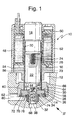
- Solenoid valve 10 is a rotationally symmetrical, in its normally closed 2/2-way valve. It is in a stepped receiving bore 12 in one Hydraulic block 14 used.
- hydraulic components such as solenoid valves and hydraulic pumps are used and hydraulically interconnected.
- the solenoid valve 10 has a valve dome 16 cylindrical tube, one end of which has a solid, cylindrical pole piece 18 is closed, with the valve dome 16 through a circumferential weld 20 is sealed pressure-tight and fluid-tight. On the pole piece 18 is then a cylindrical armature 22 axially displaceable recorded in the valve dome 16.
- a valve closing spring 24 in the form of a Helical compression spring which is inserted into an axial blind hole 26 in the armature 22, pushes the armature 22 from the pole piece 18.
- the armature 22 is provided with continuous longitudinal grooves 23 which a Flowing fluid allow the resistance to movement of the To keep armature 22 low when actuating solenoid valve 10.
- valve seat part 32 is arranged in the open end 28 of the valve dome 16.
- the Valve seat part 32 is cylindrical with a significantly smaller diameter than that Valve dome 16. It is in a yoke-shaped valve seat part holder 34 pressed in the ring step 30 on the open end face 28 of the valve dome 16 lies.
- By an obliquely inward flare 36 on the open end 28 of the valve dome 16 is the valve seat part holder 34 with the Valve seat part 32 held in the open end face 28 of the valve dome 16.
- the perforated disc-shaped valve seat part holder 34 is an easy to manufacture, affordable standard part.
- the valve seat part 32 is provided with an axial through hole 38 which a constriction as a throttle point 40 at an end facing the armature 22 has and opens with a conical valve seat 42 to the armature 22 out.
- the Through hole 38 with the throttle point 40 forms a valve outlet.
- the Valve seat part 32 has no undercut, it is due to cold knocking, So produced quickly and inexpensively by a forming process.
- the Valve seat 42 can be embossed after cold-striking Achieve material consolidation and increase its wear resistance.
- the Valve seat part 32 can also be made in one piece with valve seat part holder 34 his.
- the armature tapers at its end facing the valve seat part 32 22 with two ring steps.
- a hardened ball as Pressed valve closing body 46, which cooperates with the valve seat 42.
- the armature 22 is with the valve closing body 46 pressed into it by the Valve closing spring 24 pressed against the valve seat 42, d. H. the magnetic valve 10 is closed in its de-energized basic position.
- the valve dome 16 and the pole piece 18 surrounding coil 48 By Energizing the coil 48, the armature 22 against the force of Valve closing spring 24 is attracted to the pole piece 18 and in this way the Valve closing body 46 is lifted off the valve seat 42, the magnetic valve 10 is in its energized switch position open.
- the coil 48 is with a Cast plastic insulator 50 and inserted into a cup-shaped yoke 52, the a magnetic circuit of the solenoid valve 10 at a free end of the Pol Cultures 18 closes.
- a yoke plate 54 In a front end facing the hydraulic block 14 of the yoke 52, a yoke plate 54 is inserted with a central hole 56, the is penetrated by the valve dome 16. With the yoke 54 is also on the Side of the armature 22 of the magnetic circuit of the solenoid valve 10 largely closed.
- the perforated disk-shaped valve seat part holder 34 has a position on it Inner circumference, that is, on the outer circumference of the valve seat part 32, an axially parallel continuous longitudinal groove 37, which is part of a valve inlet.
- This Longitudinal groove 37 forms a throttle point.
- Valve inlet 37 and valve outlet 38, 40 thus take place through the open end face 28 of the valve dome 16, so that no transverse hole in the peripheral wall of the valve dome 16 or in any other Part of the solenoid valve 10 is necessary for the valve inlet or outlet, which is the Manufacture of the solenoid valve 10 facilitated.
- the solenoid valve 10 has an annular shape Valve carrier 58, which is attached to the valve dome 16.
- the valve carrier 58 has a ring step 60 on its inside, in which the ring step 30 of the Valve domes 16 and the valve seat part holder 34 lie therein.
- the interference fit between the valve dome 16 and the Valve seat part holder 34 can by pressing the valve carrier 58 onto the Valve dome 16 can be effected, so it does not have to be an interference fit in every case exist between the valve seat part holder 34 and the valve dome 16, as long as the valve support 58 has not yet been pressed on.
- a circular caulking 62 of the valve support 58 improves the mechanical connection and the Flameproof seal between the valve support 58, the valve dome 16 and the valve seat part holder 34.
- the caulking 62 additionally causes one Positive locking to the frictional connection.
- the valve carrier 58 also has an annular step 64 on its outer circumference on which he and together with him the entire solenoid valve 10 by a encircling caulking 66 of the hydraulic block 14 in the receiving bore 12 of the hydraulic block 14 is held and sealed pressure-tight.
- the Caulking 66 is applied before the coil 48 with the yoke 52 on the Valve dome 16 and the pole piece 18 are plugged on.
- the valve seat part 32 is on a side facing away from the armature 22 from the Valve seat part holder 34 in an axial outlet bore 68 in hydraulic block 14 into it.
- a filter element 70 arranged, which has the shape of a perforated disk 70, the surrounding the valve seat part holder 34 projecting valve seat part 32 and that for example from a filter fabric or a perforated filter screen consists.
- the filter element 70 is partially made of a thermoplastic overmoulded, preferably about 20% glass or carbon fiber added are.
- the filter element 70 lies in a flat countersink of the valve support 58 on.
- thermoplastic material of the filter element 70 fulfills several Sealing functions: On the one hand, the thermoplastic is a sealing ring 72 formed on the outer circumference of the filter element 70. Furthermore, the thermoplastic an annular sealing element 74 on the inner circumference of the yoke-shaped filter element 70. This is the valve seat part 32 enclosing, annular sealing element 74 has a U-shaped ring cross section on, the open side of the valve seat part holder 34 and the closed yoke side facing away from the valve seat part holder 34, so that a Interior of the U-shaped ring cross section of the sealing element 74 with a fluid pressure prevailing in the valve inlet.
- An inner one Leg 76 of the U-shaped ring cross section lies sealingly on the outside Valve seat part 32, an outer leg 78 of the U-shaped ring cross section of the Sealing element 74 is sealingly inside on a peripheral wall of the stepped Receiving bore 12 of the hydraulic block 14.
- valve inlet is through a radial inlet bore 80, which leads to the filter element 70, further through the filter element 70 and by one or more radial grooves 82 in the sealing element 74 which Form throttling points, and through the longitudinal groove 37 of the valve seat part holder 34 in the interior of the valve dome 16.
Landscapes
- Physics & Mathematics (AREA)
- Electromagnetism (AREA)
- Engineering & Computer Science (AREA)
- Fluid Mechanics (AREA)
- Transportation (AREA)
- Mechanical Engineering (AREA)
- Magnetically Actuated Valves (AREA)
- Regulating Braking Force (AREA)
Applications Claiming Priority (3)
| Application Number | Priority Date | Filing Date | Title |
|---|---|---|---|
| DE19807130A DE19807130A1 (de) | 1998-02-20 | 1998-02-20 | Magnetventil für eine schlupfgeregelte, hydraulische Fahrzeugbremsanlage |
| DE19807130 | 1998-02-20 | ||
| PCT/DE1998/003400 WO1999042348A1 (de) | 1998-02-20 | 1998-11-18 | Magnetventil für eine schlupfgeregelte, hydraulische fahrzeugbremsanlage |
Publications (2)
| Publication Number | Publication Date |
|---|---|
| EP1056631A1 EP1056631A1 (de) | 2000-12-06 |
| EP1056631B1 true EP1056631B1 (de) | 2002-10-02 |
Family
ID=7858385
Family Applications (1)
| Application Number | Title | Priority Date | Filing Date |
|---|---|---|---|
| EP98966150A Expired - Lifetime EP1056631B1 (de) | 1998-02-20 | 1998-11-18 | Magnetventil für eine schlupfgeregelte, hydraulische fahrzeugbremsanlage |
Country Status (5)
| Country | Link |
|---|---|
| US (1) | US6405752B1 (enExample) |
| EP (1) | EP1056631B1 (enExample) |
| JP (1) | JP4436967B2 (enExample) |
| DE (2) | DE19807130A1 (enExample) |
| WO (1) | WO1999042348A1 (enExample) |
Families Citing this family (35)
| Publication number | Priority date | Publication date | Assignee | Title |
|---|---|---|---|---|
| DE19943532A1 (de) * | 1999-05-14 | 2000-11-16 | Continental Teves Ag & Co Ohg | Elektromagnetventil |
| DE19951665B4 (de) * | 1999-10-26 | 2010-01-14 | Continental Teves Ag & Co. Ohg | Elektromagnetventil, insbesondere für hydraulische Bremsanlagen mit Schlupfregelung |
| DE10010734A1 (de) * | 2000-03-04 | 2001-09-06 | Continental Teves Ag & Co Ohg | Elektromagnetventil, insbesondere für schlupfgeregelte Kraftfahrzeugbremsanlagen |
| KR100423642B1 (ko) * | 2000-06-02 | 2004-03-22 | 주식회사 만도 | 브레이크시스템용 솔레노이드밸브 |
| DE10038091B4 (de) | 2000-08-04 | 2009-01-15 | Robert Bosch Gmbh | Magnetventil, insbesondere für eine schlupfgeregelte, hydraulische Fahrzeugbremsanlage |
| DE10064169A1 (de) * | 2000-08-08 | 2002-02-21 | Continental Teves Ag & Co Ohg | Elektromagnetventil |
| DE10212040A1 (de) * | 2002-01-14 | 2003-07-24 | Continental Teves Ag & Co Ohg | Elektromagnetventil, insbesondere für schlupfgeregelte Kraftfahrzeugbremsanlagen |
| JP4012792B2 (ja) * | 2002-09-17 | 2007-11-21 | 日信工業株式会社 | 電磁弁 |
| JP4432681B2 (ja) * | 2003-10-06 | 2010-03-17 | 株式会社アドヴィックス | ブレーキ用流体制御装置 |
| US7325566B2 (en) * | 2004-02-10 | 2008-02-05 | Sloan Valve Company | Filtering seal for a fluid control valve |
| DE102004050221A1 (de) * | 2004-10-15 | 2006-04-27 | Robert Bosch Gmbh | Elektromagnetisch betätigbares Ventil, insbesondere für Bremskraftanlagen in Fahrzeugen |
| KR100926119B1 (ko) | 2004-12-15 | 2009-11-11 | 주식회사 만도 | 브레이크 시스템용 솔레노이드 밸브 |
| US7726630B2 (en) * | 2005-05-20 | 2010-06-01 | Parker-Hannifin Corporation | Solenoid valve |
| KR100632440B1 (ko) | 2005-09-08 | 2006-10-11 | 주식회사 만도 | 안티록 브레이크 시스템용 솔레노이드 밸브 |
| KR100839753B1 (ko) * | 2006-06-23 | 2008-06-19 | 현대모비스 주식회사 | 브레이크 오일 흐름 제어용 솔레노이드 밸브 |
| DE102006045162A1 (de) | 2006-09-25 | 2008-04-03 | Robert Bosch Gmbh | Hydraulikblock |
| DE102007028516A1 (de) * | 2007-06-21 | 2008-12-24 | Robert Bosch Gmbh | Magnetventil |
| DE102007034032A1 (de) * | 2007-07-20 | 2009-01-22 | Robert Bosch Gmbh | Verfahren und Vorrichtung zur Herstellung einer hochdruckdichten Verbindung und zugehörige Ventilpatrone für ein Magnetventil |
| DE102008014408A1 (de) * | 2007-10-11 | 2009-04-23 | Mando Corp., Pyungtaek | Ventil für ein Antiblockierbremssystem |
| KR100847744B1 (ko) * | 2007-10-11 | 2008-07-22 | 주식회사 만도 | 브레이크시스템용 솔레노이드밸브 |
| US8430377B2 (en) * | 2008-03-26 | 2013-04-30 | Parker-Hannifin Corporation | Valve |
| US7975982B2 (en) * | 2008-09-03 | 2011-07-12 | Defond Components Limited | Electromagnetic valve |
| DE102008060889B4 (de) | 2008-12-09 | 2022-08-25 | Pierburg Gmbh | Druckregelventil |
| US9645585B2 (en) * | 2009-01-15 | 2017-05-09 | Robertshaw Controls Company | Variable flow digital gas valve |
| DE102009060294A1 (de) * | 2009-12-23 | 2011-06-30 | Robert Bosch GmbH, 70469 | Magnetventil sowie Fahrerassistenzeinrichtung |
| DE102009060729A1 (de) * | 2009-12-29 | 2011-07-14 | Robert Bosch GmbH, 70469 | Ventilanordnung |
| JP5837000B2 (ja) | 2013-05-24 | 2015-12-24 | 日信工業株式会社 | 車両用ブレーキ液圧制御装置および車両用ブレーキ液圧制御装置の製造方法 |
| CN105518361B (zh) | 2013-06-10 | 2017-11-07 | 沃尔布罗有限责任公司 | 低成本电磁阀 |
| DE102013213817A1 (de) * | 2013-07-15 | 2014-10-23 | E.G.O. Elektro-Gerätebau GmbH | Führungsrohr, Ventil und Verfahren zur Herstellung eines Ventils |
| EP3261102A1 (en) | 2016-06-23 | 2017-12-27 | Rain Bird Corporation | Universal solenoid |
| CN106314410B (zh) * | 2016-06-28 | 2023-04-11 | 浙江万安科技股份有限公司 | 双管路挂车制动阀 |
| US10980120B2 (en) | 2017-06-15 | 2021-04-13 | Rain Bird Corporation | Compact printed circuit board |
| US11503782B2 (en) | 2018-04-11 | 2022-11-22 | Rain Bird Corporation | Smart drip irrigation emitter |
| US11287050B2 (en) | 2019-05-02 | 2022-03-29 | Automatic Switch Company | Solenoid valve with crimp fitting |
| US11721465B2 (en) | 2020-04-24 | 2023-08-08 | Rain Bird Corporation | Solenoid apparatus and methods of assembly |
Family Cites Families (10)
| Publication number | Priority date | Publication date | Assignee | Title |
|---|---|---|---|---|
| US4610428A (en) * | 1985-03-11 | 1986-09-09 | Borg-Warner Automotive, Inc. | Hermetically sealed electromagnetic solenoid valve |
| DE4030971A1 (de) * | 1990-10-01 | 1992-04-02 | Bosch Gmbh Robert | Elektromagnetbetaetigtes ventil |
| US5232196A (en) * | 1992-03-31 | 1993-08-03 | Ldi Pneutronics Corporation | Proportional solenoid controlled valve |
| JP2588365Y2 (ja) * | 1992-06-23 | 1999-01-06 | 株式会社ユニシアジェックス | 圧力制御弁 |
| US5791747A (en) * | 1994-02-18 | 1998-08-11 | Kelsey-Hayes Company | Hydraulic valve control unit for vehicular anti-lock brake and traction control systems |
| KR970001879B1 (ko) | 1994-03-30 | 1997-02-18 | 닛신 고오교오 가부시끼가이샤 | 차량용 안티록브레이크 제어장치 |
| JP3613628B2 (ja) * | 1996-01-12 | 2005-01-26 | 日清紡績株式会社 | 電磁弁装置 |
| DE19635691A1 (de) * | 1996-09-03 | 1998-03-05 | Bosch Gmbh Robert | Magnetventil für eine schlupfgeregelte, hydraulische Fahrzeugbremsanlage |
| DE19635693A1 (de) * | 1996-09-03 | 1998-03-05 | Bosch Gmbh Robert | Magnetventil für eine schlupfgeregelte, hydraulische Fahrzeugbremsanlage |
| US6050542A (en) * | 1998-06-03 | 2000-04-18 | Snap-Tite Technologies, Inc. | Low power solenoid proportional valve |
-
1998
- 1998-02-20 DE DE19807130A patent/DE19807130A1/de not_active Withdrawn
- 1998-11-18 EP EP98966150A patent/EP1056631B1/de not_active Expired - Lifetime
- 1998-11-18 DE DE59805854T patent/DE59805854D1/de not_active Expired - Lifetime
- 1998-11-18 US US09/622,647 patent/US6405752B1/en not_active Expired - Lifetime
- 1998-11-18 WO PCT/DE1998/003400 patent/WO1999042348A1/de not_active Ceased
- 1998-11-18 JP JP2000532320A patent/JP4436967B2/ja not_active Expired - Fee Related
Also Published As
| Publication number | Publication date |
|---|---|
| EP1056631A1 (de) | 2000-12-06 |
| JP2002503589A (ja) | 2002-02-05 |
| JP4436967B2 (ja) | 2010-03-24 |
| US6405752B1 (en) | 2002-06-18 |
| DE59805854D1 (de) | 2002-11-07 |
| WO1999042348A1 (de) | 1999-08-26 |
| DE19807130A1 (de) | 1999-08-26 |
Similar Documents
| Publication | Publication Date | Title |
|---|---|---|
| EP1056631B1 (de) | Magnetventil für eine schlupfgeregelte, hydraulische fahrzeugbremsanlage | |
| EP0923476B1 (de) | Magnetventil für eine schlupfgeregelte, hydraulische fahrzeugbremsanlage | |
| EP0971833B1 (de) | Magnetventil mit integriertem rückschlagventil | |
| EP0923475B1 (de) | Magnetventil für eine schlupfgeregelte, hydraulische fahrzeugbremsanlage | |
| EP2337716B1 (de) | Magnetventil | |
| EP0720551B1 (de) | Hydraulikaggregat für schlupfgeregelte bremsanlagen von kraftfahrzeugen | |
| DE102005014100B4 (de) | Elektromagnetventil, insbesondere für schlupfgeregelte Kraftfahrzeugbremsanlagen | |
| DE10321413B4 (de) | Elektromagnetisch betätigbares Ventil | |
| EP1030973B1 (de) | Kolbenpumpe | |
| DE19531010B4 (de) | Magnetventil, insbesondere für eine schlupfgeregelte, hydraulische Bremsanlage für Kraftfahrzeuge | |
| DE4329211A1 (de) | Hubkolbenpumpe mit einem Gehäuseblock und wenigstens einem Hubkolbenpumpenelement | |
| EP1115604A1 (de) | Magnetventil, insbesondere für eine schlupfgeregelte, hydraulische fahrzeugbremsanlage | |
| DE19910207A1 (de) | Ventil, insbesondere für schlupfgeregelte hydraulische Bremsanlagen von Kraftfahrzeugen | |
| DE4030963A1 (de) | Elektromagnetbetaetigtes ventil | |
| DE19635690B4 (de) | Magnetventil für eine schlupfgeregelte, hydraulische Fahrzeugbremsanlage | |
| WO2021018341A1 (de) | Ventil und vorrichtung zur regelung von drücken eines strömungsmittels mit dem ventil sowie vorrichtung zur sicherung des ventils in dem getriebebauteil | |
| DE4330325A1 (de) | Elektromagnetisch betätigbares Ventil | |
| DE102007026358B4 (de) | Elektromagnetventil, insbesondere für schlupfgeregelte Kraftfahrzeugbremsanlagen | |
| WO2008110438A1 (de) | Elektromagnetventil | |
| DE102021204203A1 (de) | Elektromagnetventil, insbesondere für schlupfgeregelte Kraftfahrzeugbremsanlagen | |
| DE10002269A1 (de) | Magnetventil für ein schlupfgeregelte, hydraulische Fahrzeugbremsanlage | |
| WO1992014636A1 (de) | Magnetventil für hydraulische kraftfahrzeug-bremsanlagen mit blockierschutzeinrichtung | |
| DE19838910A1 (de) | Elektromagnetische Vorrichtung, insbesondere für eine schlupfgeregelte, hydraulische Fahrzeugbremsanlage | |
| DE4137244C2 (de) | Kolbenventilanordnung und Verfahren zur Montage einer solchen Kolbenventilanordnung | |
| WO2026008161A1 (de) | Fluidventilvorrichtung |
Legal Events
| Date | Code | Title | Description |
|---|---|---|---|
| PUAI | Public reference made under article 153(3) epc to a published international application that has entered the european phase |
Free format text: ORIGINAL CODE: 0009012 |
|
| 17P | Request for examination filed |
Effective date: 20000920 |
|
| AK | Designated contracting states |
Kind code of ref document: A1 Designated state(s): DE FR GB |
|
| GRAG | Despatch of communication of intention to grant |
Free format text: ORIGINAL CODE: EPIDOS AGRA |
|
| 17Q | First examination report despatched |
Effective date: 20020207 |
|
| GRAG | Despatch of communication of intention to grant |
Free format text: ORIGINAL CODE: EPIDOS AGRA |
|
| GRAH | Despatch of communication of intention to grant a patent |
Free format text: ORIGINAL CODE: EPIDOS IGRA |
|
| GRAH | Despatch of communication of intention to grant a patent |
Free format text: ORIGINAL CODE: EPIDOS IGRA |
|
| GRAA | (expected) grant |
Free format text: ORIGINAL CODE: 0009210 |
|
| AK | Designated contracting states |
Kind code of ref document: B1 Designated state(s): DE FR GB |
|
| REG | Reference to a national code |
Ref country code: GB Ref legal event code: FG4D Free format text: NOT ENGLISH |
|
| REF | Corresponds to: |
Ref document number: 59805854 Country of ref document: DE Date of ref document: 20021107 |
|
| GBT | Gb: translation of ep patent filed (gb section 77(6)(a)/1977) |
Effective date: 20030113 |
|
| ET | Fr: translation filed | ||
| PLBE | No opposition filed within time limit |
Free format text: ORIGINAL CODE: 0009261 |
|
| STAA | Information on the status of an ep patent application or granted ep patent |
Free format text: STATUS: NO OPPOSITION FILED WITHIN TIME LIMIT |
|
| 26N | No opposition filed |
Effective date: 20030703 |
|
| PGFP | Annual fee paid to national office [announced via postgrant information from national office to epo] |
Ref country code: FR Payment date: 20031119 Year of fee payment: 6 |
|
| PG25 | Lapsed in a contracting state [announced via postgrant information from national office to epo] |
Ref country code: FR Free format text: LAPSE BECAUSE OF NON-PAYMENT OF DUE FEES Effective date: 20050729 |
|
| REG | Reference to a national code |
Ref country code: FR Ref legal event code: ST |
|
| PGFP | Annual fee paid to national office [announced via postgrant information from national office to epo] |
Ref country code: GB Payment date: 20131122 Year of fee payment: 16 |
|
| REG | Reference to a national code |
Ref country code: DE Ref legal event code: R084 Ref document number: 59805854 Country of ref document: DE |
|
| REG | Reference to a national code |
Ref country code: DE Ref legal event code: R084 Ref document number: 59805854 Country of ref document: DE Effective date: 20141114 |
|
| GBPC | Gb: european patent ceased through non-payment of renewal fee |
Effective date: 20141118 |
|
| PG25 | Lapsed in a contracting state [announced via postgrant information from national office to epo] |
Ref country code: GB Free format text: LAPSE BECAUSE OF NON-PAYMENT OF DUE FEES Effective date: 20141118 |
|
| PGFP | Annual fee paid to national office [announced via postgrant information from national office to epo] |
Ref country code: DE Payment date: 20180125 Year of fee payment: 20 |
|
| REG | Reference to a national code |
Ref country code: DE Ref legal event code: R071 Ref document number: 59805854 Country of ref document: DE |