EP0907538B1 - Sitzventil für hydraulische kraftfahrzeug-bremsanlagen - Google Patents
Sitzventil für hydraulische kraftfahrzeug-bremsanlagen Download PDFInfo
- Publication number
- EP0907538B1 EP0907538B1 EP97927146A EP97927146A EP0907538B1 EP 0907538 B1 EP0907538 B1 EP 0907538B1 EP 97927146 A EP97927146 A EP 97927146A EP 97927146 A EP97927146 A EP 97927146A EP 0907538 B1 EP0907538 B1 EP 0907538B1
- Authority
- EP
- European Patent Office
- Prior art keywords
- valve
- seat
- pressure
- retaining member
- closure member
- Prior art date
- Legal status (The legal status is an assumption and is not a legal conclusion. Google has not performed a legal analysis and makes no representation as to the accuracy of the status listed.)
- Expired - Lifetime
Links
- 239000012530 fluid Substances 0.000 claims description 11
- 230000000694 effects Effects 0.000 claims description 5
- 238000000034 method Methods 0.000 claims description 3
- 230000003313 weakening effect Effects 0.000 claims description 2
- 230000003134 recirculating effect Effects 0.000 claims 3
- 230000004913 activation Effects 0.000 claims 1
- 230000000717 retained effect Effects 0.000 claims 1
- 230000005284 excitation Effects 0.000 description 5
- 230000009172 bursting Effects 0.000 description 4
- 238000000465 moulding Methods 0.000 description 3
- 238000004519 manufacturing process Methods 0.000 description 2
- 238000007493 shaping process Methods 0.000 description 2
- 230000000903 blocking effect Effects 0.000 description 1
- 230000006378 damage Effects 0.000 description 1
- 230000001419 dependent effect Effects 0.000 description 1
- 210000003746 feather Anatomy 0.000 description 1
- 238000005429 filling process Methods 0.000 description 1
- 238000010438 heat treatment Methods 0.000 description 1
- 239000002184 metal Substances 0.000 description 1
- 125000006850 spacer group Chemical group 0.000 description 1
Images
Classifications
-
- B—PERFORMING OPERATIONS; TRANSPORTING
- B60—VEHICLES IN GENERAL
- B60T—VEHICLE BRAKE CONTROL SYSTEMS OR PARTS THEREOF; BRAKE CONTROL SYSTEMS OR PARTS THEREOF, IN GENERAL; ARRANGEMENT OF BRAKING ELEMENTS ON VEHICLES IN GENERAL; PORTABLE DEVICES FOR PREVENTING UNWANTED MOVEMENT OF VEHICLES; VEHICLE MODIFICATIONS TO FACILITATE COOLING OF BRAKES
- B60T8/00—Arrangements for adjusting wheel-braking force to meet varying vehicular or ground-surface conditions, e.g. limiting or varying distribution of braking force
- B60T8/32—Arrangements for adjusting wheel-braking force to meet varying vehicular or ground-surface conditions, e.g. limiting or varying distribution of braking force responsive to a speed condition, e.g. acceleration or deceleration
- B60T8/34—Arrangements for adjusting wheel-braking force to meet varying vehicular or ground-surface conditions, e.g. limiting or varying distribution of braking force responsive to a speed condition, e.g. acceleration or deceleration having a fluid pressure regulator responsive to a speed condition
- B60T8/36—Arrangements for adjusting wheel-braking force to meet varying vehicular or ground-surface conditions, e.g. limiting or varying distribution of braking force responsive to a speed condition, e.g. acceleration or deceleration having a fluid pressure regulator responsive to a speed condition including a pilot valve responding to an electromagnetic force
- B60T8/3615—Electromagnetic valves specially adapted for anti-lock brake and traction control systems
- B60T8/363—Electromagnetic valves specially adapted for anti-lock brake and traction control systems in hydraulic systems
-
- F—MECHANICAL ENGINEERING; LIGHTING; HEATING; WEAPONS; BLASTING
- F16—ENGINEERING ELEMENTS AND UNITS; GENERAL MEASURES FOR PRODUCING AND MAINTAINING EFFECTIVE FUNCTIONING OF MACHINES OR INSTALLATIONS; THERMAL INSULATION IN GENERAL
- F16K—VALVES; TAPS; COCKS; ACTUATING-FLOATS; DEVICES FOR VENTING OR AERATING
- F16K31/00—Actuating devices; Operating means; Releasing devices
- F16K31/02—Actuating devices; Operating means; Releasing devices electric; magnetic
- F16K31/06—Actuating devices; Operating means; Releasing devices electric; magnetic using a magnet, e.g. diaphragm valves, cutting off by means of a liquid
- F16K31/0644—One-way valve
- F16K31/0655—Lift valves
- F16K31/0665—Lift valves with valve member being at least partially ball-shaped
Definitions
- the invention relates to a seat valve for hydraulic Motor vehicle braking systems with wheel slip control according to the preamble of claim 1.
- a seat valve of the generic type is already out of the US-A-4,056,255.
- the poppet valve points to Locking the valve closing member in its open position a permanent magnet attached in the area of the magnetic core whose magnetic circuit depends on the magnetic circuit of one magnet coil attached below the permanent magnet determines the switching position of the seat valve.
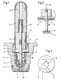
- valve housing 1 shows a sectional view of a seat valve on a much larger scale
- the cartridge design has a valve housing 1, in the lower end of which Valve seat body 4 is attached.
- the valve seat body 4 facing end face portion of the valve housing 1 closed by means of a dome-like valve sleeve 8, which with its open end section between the valve housing 1 and a socket inserted into the valve housing 1 caulked is kept and sealed.
- a disc-shaped Holding part 2 pressure-tight clamped, the Center opening 15 of a tappet-shaped valve closing member 3 is permeated.
- the valve closing member 3 is with his one end in the illustration of the valve seat body 4 spaced, with which a pressure medium connection between that located below the valve seat body 4 Pressure medium channel 10 and that above the valve seat body 4 in the valve housing 1 radially opening pressure medium channel 11 exists.
- the switching position of the seat valve shown 1 thus shows the essence of the invention, according to which in Valve housing 1 is a holding part 2 is fixed, according to the Actuation of the valve closing member 3 from the closed Basic position in the operating position shown in the illustration, the valve closing member 3 in the valve seat body 4 lifted position locked.
- the locking of the holding part 2 on the tappet-shaped section of the valve closing member 3 can be both positive and / or non-positive.
- valve closing element 3 in its open position is done by electromagnetic Excitation of a mounted on the valve sleeve 8, valve coil not shown in the drawing.
- FIG. 2 shows the deformation of the Holding part 2 under the effect of the bursting pressure in the pressure chamber 7, the tongue-like gaping apart of the holding part 2 leads in the area of its central opening 15, which is Can release valve closing member 3 from the holding part 2 and under Effect of the spring 14 in the direction of the valve closing position is moved. So far with regard to Fig. 2 not on all details is received, these still correspond to those in embodiments shown for their essence for the seat valve according to Fig. 1.
- FIG. 3 shows a top view of that known from FIG. 1 Holding part 2.
- Leave outside the pane contour of holding part 2 preferably attached on both sides of the central opening 15 Notches in the surface of the holding part 2 recognize that with appropriate hydraulic pressurization form the predetermined breaking points 5. This is done accordingly the representation of the holding part known from FIG. 2 the desired, tongue-shaped extension of the holding part 2 in the area of the central opening 15.
- the expansion of the Center opening 15 can both after the bursting by appropriate shaping of the predetermined breaking points 5 as also by appropriate heat treatment, preferably consisting of an anti-magnetic thin sheet metal part 2 can be influenced specifically.
- the holding part 2 an aperture 6, which ensures that during the evacuation process within both pressure medium channels 10,11 not only the one facing the pressure medium channels 10,11 Pressure chamber 7, but also the one above the holding part 2 evacuated into the valve sleeve 8 extending pressure chamber 7 ' can be. This is also an evacuation of the relative small pressure chamber 7 'ensured.
- valve closing member 3 Under Effect of the spring 14 first on the valve seat body 4. So far no impermissible leakage losses from the pressure medium channel 10 to Pressure medium channel 11 enter, is by electromagnetic Excitation of the seat valve, the valve closing member 3 from the valve seat body 4 lifted off and shown in the illustration locked in Fig. 1. Stuck in this state it until the evacuation and filling of the brake system and Commissioning in the motor vehicle. As already mentioned, will the locking of the holding part 2 on the valve closing member 3 canceled when the burst pressure is reached. With that is under Reference to the illustration of FIG. 2 ensures that the seat valve is ready for operation with the brakes.
- the valve closing member 3 can then within the framework of a blocking pressure control or traction control only for the duration of one acting on the magnet armature Current pulse open and picks up after completion electromagnetic excitation unimpeded by action the spring 14 its valve position closed in the basic position on.
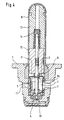
- FIG. 4 An alternative embodiment of the seat valve starts Fig. 4 out.
- this is essentially disc-shaped designed holding part 2 both on the outer circumference and a collar or webs also in the area of the central opening 15 has, which is on the outer circumference of the holding part 2 in the area of the valve housing 1 and in the area of the center opening 15 support on the end face of the magnet armature 12.
- Depending on the space available can either be on the web or Collar area on the outer circumference or on the inner circumference of the holding part 2 can be dispensed with.
- the web or collar height is at least the required Opening stroke of the valve closing member 3 corresponds to the desired evacuation as well as high pressure filling of the Ensure pressure medium channels 10.11.
- the holding part 2 also has at least one end face side annular cross-sectional weakening that the function a predetermined breaking point 5 takes over.
- the holding part 2 is preferably made of a plastic that after evacuation of the channels and cavities in the area of the seat valve is exposed to the hydraulic filling pressure and the broken down into two hollow bodies when the burst pressure is reached.
- the inner hollow body supported on the magnet armature 12 is attached by means of a valve closing member 3 Molding 16 secured, while the outer hollow body as shown on the ring filter and thus also in the original position remains in the valve housing 1.
- the invention thus leads to the result that the secondary circuit, i.e. the brake pipe section between the in Home position closed seat valve and the downstream Pressure medium device according to the return flow principle working brake system remarkably easy evacuated and can be filled if the seat valve by means of a effective rupture disc for the time phase of the Evacuation and filling remains open.
- the holding part or the filling pressure of the brake system can be designed so that after filling the secondary circuit, the holding part the predetermined breaking points burst, causing the valve lifter to the valve closing member is released from the holding part and which closes the seat valve.
- an increased hydraulic if necessary Pressure pulse during filling for the destruction of the holding part can be integrated cost-effectively.
Landscapes
- Engineering & Computer Science (AREA)
- Physics & Mathematics (AREA)
- Electromagnetism (AREA)
- Mechanical Engineering (AREA)
- General Engineering & Computer Science (AREA)
- Fluid Mechanics (AREA)
- Transportation (AREA)
- Valves And Accessory Devices For Braking Systems (AREA)
- Magnetically Actuated Valves (AREA)
Abstract
Description
- Fig. 1
- ein mittels erfindungsgemäßem Halteteil in Offenstellung arretiertes Sitzventil,
- Fig. 2
- den Erfindungsgegenstand nach Fig. 1 nach Evakuierung und Befüllung der am Sitzventil angeschlossenen Druckmittelkanäle,
- Fig. 3
- eine Draufsicht auf eine Ausführungsform für das erfindungsgemäße Halteteil,
- Fig. 4
- eine weitere Ausführungsform eines im Sitzventil integrierten Halteteils.
- 1
- Ventilgehäuse
- 2
- Halteteil
- 3
- Ventilschließglied
- 4
- Ventilsitzkörper
- 5
- Sollbruchstelle
- 6
- Blendenöffnung
- 7,7'
- Druckraum
- 8
- Ventilhülse
- 9
- Buchse
- 10
- Druckmittelkanal
- 11
- Druckmittelkanal
- 12
- Magnetanker
- 13
- Magnetkern
- 14
- Feder
- 15
- Mittenöffnung
- 16
- Formteil
- 17
- Gummierung
Claims (7)
- Sitzventil für hydraulische Kraftfahrzeugbremsanlagen mit Radschlupfregelung, mit einem Ventilgehäuse (1), das wenigstens einen Ventilsitzkörper (4) und ein Ventilschließglied (3) aufnimmt, wobei das Ventilschließglied (3) in der Grundstellung normalerweise am Ventilsitzkörper (4) anliegt, so daß eine Druckmittelverbindung zwischen einem ersten und wenigstens einem zweiten Druckmittelkanal (10, 11) getrennt ist, in der Betriebsstellung das Ventilschließglied (3) vom Ventilsitzkörper (4) abgehoben ist und die vorgenannte Druckmittelverbindung zwischen den Druckmittelkanälen (10, 11) herstellt, wobei im Ventilgehäuse (1) ein Halteteil (2) fixiert ist, das das Ventilschließglied (3) in der vom Ventilsitzkörper (4) abgehobenen Stellung arretiert, dadurch gekennzeichnet, daß das Halteteil (2) unter Wirkung eines definierten hydraulischen Drucks im Ventilgehäuse (1) eine Gestaltsanderung aufweist, in der das Ventilschließglied (3) vom Halteteil (2) freigegeben ist.
- Sitzventil nach Anspruch 1, dadurch gekennzeichnet, daß das Halteteil (2) nach Betätigung des Ventilschließglieds (3) in die Offenstellung form- und/oder kraftschlüssig mit einem Stößelabschnitt des Ventilschließgliedes (3) in Eingriff steht.
- Sitzventil nach Anspruch 1 oder 2, dadurch gekennzeichnet, daß das Halteteil (2) wenigstens eine örtliche Querschnittsschwächung, vorzugsweise Sollbruchstelle (5) aufweist, durch die unter Einwirkung eines definierten hydraulischen Drucks im Ventilgehäuse (1) das Ventilschließglied (3) vom Halteteil (2) freigegeben ist.
- Sitzventil nach Anspruch 1, dadurch gekennzeichnet, daß eine in Richtung auf den Ventilsitzkörper (4) wirksame Feder (14) am Ventilschließglied (3) angeordnet ist.
- Sitzventil nach einem der vorhergehenden Ansprtche 1 bis 3, dadurch gekennzeichnet, daß im Halteteil (2) und/oder zwischen dem Halteteil (2) und dem Ventilschließglied (3) wenigstens eine Blendenöffnung (6) vorgesehen ist, die einen zeitlich verzögerten Druckausgleich zwischen den Druckräumen (7,7') beiderseits des Halteteils (2) herstellt.
- Sitzventil nach einem der vorhergehenden Ansprüche 1 bis 3, dadurch gekennzeichnet, daß das Halteteil (2) als Berstscheibe ausgebildet ist, die druckmitteldicht zu ihrer Befestigungsstelle im Ventilgehäuse (1) gehalten ist.
- Verfahren zum Betrieb einer zur Radschlupfregelung nach dem Rückförderprinzip wirkenden hydraulischen Bremsanlage, mit einem Sitzventil, das in seiner Grundstellung normalerweise einen von einer Radbremse zu einer Rückförderpumpe führenden Druckmittelkanal getrennt hält, dadurch gekennzeichnet, daß während der Evakuierung der Bremsanlage das Sitzventil mittels eines Halteteils (2) in eine die Druckmittelverbindung zwischen Radbremse und Rückförderpumpe öffnenden Betriebsstellung arretiert wird, und daß die Arretierung zwischen dem Sitzventil und dem Halteteil (2)nach Befüllung des Druckmittelkanals (10,11) mit Bremsflüssigkeit und Erreichen eines definierten hydraulischen Drucks getrennt wird.
Applications Claiming Priority (3)
| Application Number | Priority Date | Filing Date | Title |
|---|---|---|---|
| DE19625965 | 1996-06-28 | ||
| DE19625965A DE19625965A1 (de) | 1996-06-28 | 1996-06-28 | Sitzventil für hydraulische Kraftfahrzeug-Bremsanlagen |
| PCT/EP1997/002937 WO1998000325A1 (de) | 1996-06-28 | 1997-06-06 | Sitzventil für hydraulische kraftfahrzeug-bremsanlagen |
Publications (2)
| Publication Number | Publication Date |
|---|---|
| EP0907538A1 EP0907538A1 (de) | 1999-04-14 |
| EP0907538B1 true EP0907538B1 (de) | 2002-04-03 |
Family
ID=7798306
Family Applications (1)
| Application Number | Title | Priority Date | Filing Date |
|---|---|---|---|
| EP97927146A Expired - Lifetime EP0907538B1 (de) | 1996-06-28 | 1997-06-06 | Sitzventil für hydraulische kraftfahrzeug-bremsanlagen |
Country Status (3)
| Country | Link |
|---|---|
| EP (1) | EP0907538B1 (de) |
| DE (2) | DE19625965A1 (de) |
| WO (1) | WO1998000325A1 (de) |
Family Cites Families (11)
| Publication number | Priority date | Publication date | Assignee | Title |
|---|---|---|---|---|
| GB199541A (en) * | 1922-04-19 | 1923-06-28 | Alfred Edward Farrow | Improvements in and relating to safety valves |
| GB808577A (en) * | 1956-03-27 | 1959-02-04 | Rotol Ltd | Improvements in or relating to hydraulic safety valves |
| US4056255A (en) * | 1975-05-08 | 1977-11-01 | Lace Donald A | Valve actuator |
| DE2945911A1 (de) * | 1979-11-14 | 1981-05-27 | Robert Bosch Gmbh, 7000 Stuttgart | Als druckbegrenzungs- und nachsaugventil arbeitendes, direkt gesteuertes sperrventil |
| DE3312054A1 (de) * | 1983-04-02 | 1984-10-11 | Gebrüder Sulzer AG, Winterthur | Den durchfluss eines druckmediums steuerndes umschaltventil |
| GB8618301D0 (en) * | 1986-07-26 | 1986-09-03 | Eaton Sa Monaco | Three-port fluid valve |
| GB8800389D0 (en) * | 1988-01-08 | 1988-02-10 | Lucas Ind Plc | Bleeding of anti-skid braking systems |
| DE4204417A1 (de) * | 1990-09-07 | 1993-08-19 | Teves Gmbh Alfred | Elektromagnetventil, insbesondere fuer hydraulische bremsanlagen mit schlupfregelung |
| DE4337133C2 (de) * | 1993-10-30 | 2002-10-02 | Bosch Gmbh Robert | Hydraulische Bremsanlage |
| DE4342565A1 (de) * | 1993-12-14 | 1995-06-22 | Bosch Gmbh Robert | Senkrechte hydraulische Arbeitsachse |
| DE4408166A1 (de) * | 1994-03-11 | 1995-09-14 | Teves Gmbh Alfred | Druckregelvorrichtung |
-
1996
- 1996-06-28 DE DE19625965A patent/DE19625965A1/de not_active Withdrawn
-
1997
- 1997-06-06 WO PCT/EP1997/002937 patent/WO1998000325A1/de not_active Ceased
- 1997-06-06 DE DE59706876T patent/DE59706876D1/de not_active Expired - Fee Related
- 1997-06-06 EP EP97927146A patent/EP0907538B1/de not_active Expired - Lifetime
Also Published As
| Publication number | Publication date |
|---|---|
| DE19625965A1 (de) | 1998-01-02 |
| WO1998000325A1 (de) | 1998-01-08 |
| EP0907538A1 (de) | 1999-04-14 |
| DE59706876D1 (de) | 2002-05-08 |
Similar Documents
| Publication | Publication Date | Title |
|---|---|---|
| EP1056631B1 (de) | Magnetventil für eine schlupfgeregelte, hydraulische fahrzeugbremsanlage | |
| DE3920766C2 (de) | Unterdruckbremskraftverstärker für eine schlupfgeregelte Bremsanlage | |
| EP0923475B1 (de) | Magnetventil für eine schlupfgeregelte, hydraulische fahrzeugbremsanlage | |
| EP0951412B1 (de) | Magnetventil | |
| EP0632770B1 (de) | Elektromagnetventil, insbesondere für hydraulische bremsanlagen mit schlupfregelung | |
| DE19531010B4 (de) | Magnetventil, insbesondere für eine schlupfgeregelte, hydraulische Bremsanlage für Kraftfahrzeuge | |
| EP0971833A1 (de) | Magnetventil mit integriertem rückschlagventil | |
| EP1115604B1 (de) | Magnetventil, insbesondere für eine schlupfgeregelte, hydraulische fahrzeugbremsanlage | |
| DE19955888A1 (de) | Magnetventil mit einem Rückschlagventil | |
| EP0504357B1 (de) | Hauptbremszylinder für eine blockiergeschützte, hydraulische bremsanlage | |
| DE19802464A1 (de) | Hydraulisches magnetbetätigtes Sitzventil, insbesondere für Bremsanlagen von Kraftfahrzeugen | |
| EP0752942B1 (de) | Elektromagnetisch betätigtes ventil, insbesondere für schlupfgeregelte hydraulische bremsanlagen in kraftfahrzeugen | |
| DE19635690B4 (de) | Magnetventil für eine schlupfgeregelte, hydraulische Fahrzeugbremsanlage | |
| WO1995012509A1 (de) | Druckregelventil | |
| DE4433364A1 (de) | Elektromagnetisch betätigtes Ventil, insbesondere für schlupfgeregelte hydraulische Bremsanlagen in Kraftfahrzeugen | |
| DE19531009A1 (de) | Magnetventil, insbesondere für eine schlupfgeregelte, hydraulische Bremsanlage für Kraftfahrzeuge | |
| DE19511455A1 (de) | Magnetventil in einer hydraulischen Bremsanlage für Kraftfahrzeuge | |
| EP0983174B1 (de) | Hydraulische fahrzeugbremsanlage mit radschlupfregelung sowie ventil für eine solche bremsanlage | |
| WO1997018977A1 (de) | Hydraulische kraftfahrzeugbremsanlage mit radschlupfregelung | |
| EP0907538B1 (de) | Sitzventil für hydraulische kraftfahrzeug-bremsanlagen | |
| EP0796186A1 (de) | Elektromagnetisch betätigtes ventil, insbesondere für schlupfgeregelte hydraulische bremsanlagen in kraftfahrzeugen | |
| EP0720549A1 (de) | Elektromagnetisch betätigtes ventil, insbesondere für schlupfgeregelte hydraulische bremsanlagen in kraftfahrzeugen | |
| EP0915793B1 (de) | Hydraulische kraftfahrzeugbremsanlage mit radschlupfregelung | |
| DE19703759A1 (de) | Mehrwege-Regelventil | |
| DE19824500B4 (de) | Elektromagnetventil |
Legal Events
| Date | Code | Title | Description |
|---|---|---|---|
| PUAI | Public reference made under article 153(3) epc to a published international application that has entered the european phase |
Free format text: ORIGINAL CODE: 0009012 |
|
| 17P | Request for examination filed |
Effective date: 19990128 |
|
| AK | Designated contracting states |
Kind code of ref document: A1 Designated state(s): DE FR GB |
|
| RAP1 | Party data changed (applicant data changed or rights of an application transferred) |
Owner name: CONTINENTAL TEVES AG & CO. OHG |
|
| GRAG | Despatch of communication of intention to grant |
Free format text: ORIGINAL CODE: EPIDOS AGRA |
|
| 17Q | First examination report despatched |
Effective date: 20010528 |
|
| GRAG | Despatch of communication of intention to grant |
Free format text: ORIGINAL CODE: EPIDOS AGRA |
|
| GRAH | Despatch of communication of intention to grant a patent |
Free format text: ORIGINAL CODE: EPIDOS IGRA |
|
| GRAG | Despatch of communication of intention to grant |
Free format text: ORIGINAL CODE: EPIDOS AGRA |
|
| GRAH | Despatch of communication of intention to grant a patent |
Free format text: ORIGINAL CODE: EPIDOS IGRA |
|
| REG | Reference to a national code |
Ref country code: GB Ref legal event code: IF02 |
|
| GRAH | Despatch of communication of intention to grant a patent |
Free format text: ORIGINAL CODE: EPIDOS IGRA |
|
| GRAA | (expected) grant |
Free format text: ORIGINAL CODE: 0009210 |
|
| AK | Designated contracting states |
Kind code of ref document: B1 Designated state(s): DE FR GB |
|
| PG25 | Lapsed in a contracting state [announced via postgrant information from national office to epo] |
Ref country code: GB Free format text: LAPSE BECAUSE OF FAILURE TO SUBMIT A TRANSLATION OF THE DESCRIPTION OR TO PAY THE FEE WITHIN THE PRESCRIBED TIME-LIMIT Effective date: 20020403 |
|
| REF | Corresponds to: |
Ref document number: 59706876 Country of ref document: DE Date of ref document: 20020508 |
|
| ET | Fr: translation filed | ||
| ET | Fr: translation filed | ||
| GBV | Gb: ep patent (uk) treated as always having been void in accordance with gb section 77(7)/1977 [no translation filed] |
Effective date: 20020403 |
|
| PLBE | No opposition filed within time limit |
Free format text: ORIGINAL CODE: 0009261 |
|
| STAA | Information on the status of an ep patent application or granted ep patent |
Free format text: STATUS: NO OPPOSITION FILED WITHIN TIME LIMIT |
|
| 26N | No opposition filed |
Effective date: 20030106 |
|
| PGFP | Annual fee paid to national office [announced via postgrant information from national office to epo] |
Ref country code: FR Payment date: 20030618 Year of fee payment: 7 |
|
| PGFP | Annual fee paid to national office [announced via postgrant information from national office to epo] |
Ref country code: DE Payment date: 20030630 Year of fee payment: 7 |
|
| PG25 | Lapsed in a contracting state [announced via postgrant information from national office to epo] |
Ref country code: DE Free format text: LAPSE BECAUSE OF NON-PAYMENT OF DUE FEES Effective date: 20050101 |
|
| PG25 | Lapsed in a contracting state [announced via postgrant information from national office to epo] |
Ref country code: FR Free format text: LAPSE BECAUSE OF NON-PAYMENT OF DUE FEES Effective date: 20050228 |
|
| REG | Reference to a national code |
Ref country code: FR Ref legal event code: ST |